JP2011509415A - Telephoto zoom lens with liquid lens in fixed group - Google Patents
Telephoto zoom lens with liquid lens in fixed group Download PDFInfo
- Publication number
- JP2011509415A JP2011509415A JP2010536971A JP2010536971A JP2011509415A JP 2011509415 A JP2011509415 A JP 2011509415A JP 2010536971 A JP2010536971 A JP 2010536971A JP 2010536971 A JP2010536971 A JP 2010536971A JP 2011509415 A JP2011509415 A JP 2011509415A
- Authority
- JP
- Japan
- Prior art keywords
- lens
- zoom
- zoom lens
- liquid
- lens group
- Prior art date
- Legal status (The legal status is an assumption and is not a legal conclusion. Google has not performed a legal analysis and makes no representation as to the accuracy of the status listed.)
- Pending
Links
Images


Classifications
-
- G—PHYSICS
- G02—OPTICS
- G02B—OPTICAL ELEMENTS, SYSTEMS OR APPARATUS
- G02B15/00—Optical objectives with means for varying the magnification
- G02B15/14—Optical objectives with means for varying the magnification by axial movement of one or more lenses or groups of lenses relative to the image plane for continuously varying the equivalent focal length of the objective
- G02B15/143—Optical objectives with means for varying the magnification by axial movement of one or more lenses or groups of lenses relative to the image plane for continuously varying the equivalent focal length of the objective having three groups only
- G02B15/1431—Optical objectives with means for varying the magnification by axial movement of one or more lenses or groups of lenses relative to the image plane for continuously varying the equivalent focal length of the objective having three groups only the first group being positive
- G02B15/143105—Optical objectives with means for varying the magnification by axial movement of one or more lenses or groups of lenses relative to the image plane for continuously varying the equivalent focal length of the objective having three groups only the first group being positive arranged +-+
-
- G—PHYSICS
- G02—OPTICS
- G02B—OPTICAL ELEMENTS, SYSTEMS OR APPARATUS
- G02B15/00—Optical objectives with means for varying the magnification
- G02B15/14—Optical objectives with means for varying the magnification by axial movement of one or more lenses or groups of lenses relative to the image plane for continuously varying the equivalent focal length of the objective
- G02B15/142—Optical objectives with means for varying the magnification by axial movement of one or more lenses or groups of lenses relative to the image plane for continuously varying the equivalent focal length of the objective having two groups only
-
- G—PHYSICS
- G02—OPTICS
- G02B—OPTICAL ELEMENTS, SYSTEMS OR APPARATUS
- G02B13/00—Optical objectives specially designed for the purposes specified below
- G02B13/001—Miniaturised objectives for electronic devices, e.g. portable telephones, webcams, PDAs, small digital cameras
- G02B13/0055—Miniaturised objectives for electronic devices, e.g. portable telephones, webcams, PDAs, small digital cameras employing a special optical element
- G02B13/0075—Miniaturised objectives for electronic devices, e.g. portable telephones, webcams, PDAs, small digital cameras employing a special optical element having an element with variable optical properties
-
- G—PHYSICS
- G02—OPTICS
- G02B—OPTICAL ELEMENTS, SYSTEMS OR APPARATUS
- G02B13/00—Optical objectives specially designed for the purposes specified below
- G02B13/001—Miniaturised objectives for electronic devices, e.g. portable telephones, webcams, PDAs, small digital cameras
- G02B13/009—Miniaturised objectives for electronic devices, e.g. portable telephones, webcams, PDAs, small digital cameras having zoom function
-
- G—PHYSICS
- G02—OPTICS
- G02B—OPTICAL ELEMENTS, SYSTEMS OR APPARATUS
- G02B15/00—Optical objectives with means for varying the magnification
- G02B15/14—Optical objectives with means for varying the magnification by axial movement of one or more lenses or groups of lenses relative to the image plane for continuously varying the equivalent focal length of the objective
- G02B15/143—Optical objectives with means for varying the magnification by axial movement of one or more lenses or groups of lenses relative to the image plane for continuously varying the equivalent focal length of the objective having three groups only
-
- G—PHYSICS
- G02—OPTICS
- G02B—OPTICAL ELEMENTS, SYSTEMS OR APPARATUS
- G02B26/00—Optical devices or arrangements for the control of light using movable or deformable optical elements
- G02B26/004—Optical devices or arrangements for the control of light using movable or deformable optical elements based on a displacement or a deformation of a fluid
-
- G—PHYSICS
- G02—OPTICS
- G02B—OPTICAL ELEMENTS, SYSTEMS OR APPARATUS
- G02B3/00—Simple or compound lenses
- G02B3/12—Fluid-filled or evacuated lenses
- G02B3/14—Fluid-filled or evacuated lenses of variable focal length
-
- G—PHYSICS
- G03—PHOTOGRAPHY; CINEMATOGRAPHY; ANALOGOUS TECHNIQUES USING WAVES OTHER THAN OPTICAL WAVES; ELECTROGRAPHY; HOLOGRAPHY
- G03B—APPARATUS OR ARRANGEMENTS FOR TAKING PHOTOGRAPHS OR FOR PROJECTING OR VIEWING THEM; APPARATUS OR ARRANGEMENTS EMPLOYING ANALOGOUS TECHNIQUES USING WAVES OTHER THAN OPTICAL WAVES; ACCESSORIES THEREFOR
- G03B17/00—Details of cameras or camera bodies; Accessories therefor
- G03B17/02—Bodies
- G03B17/12—Bodies with means for supporting objectives, supplementary lenses, filters, masks, or turrets
-
- H—ELECTRICITY
- H04—ELECTRIC COMMUNICATION TECHNIQUE
- H04N—PICTORIAL COMMUNICATION, e.g. TELEVISION
- H04N23/00—Cameras or camera modules comprising electronic image sensors; Control thereof
- H04N23/50—Constructional details
- H04N23/55—Optical parts specially adapted for electronic image sensors; Mounting thereof
-
- G—PHYSICS
- G02—OPTICS
- G02B—OPTICAL ELEMENTS, SYSTEMS OR APPARATUS
- G02B7/00—Mountings, adjusting means, or light-tight connections, for optical elements
- G02B7/008—Mountings, adjusting means, or light-tight connections, for optical elements with means for compensating for changes in temperature or for controlling the temperature; thermal stabilisation
Landscapes
- Physics & Mathematics (AREA)
- General Physics & Mathematics (AREA)
- Optics & Photonics (AREA)
- Engineering & Computer Science (AREA)
- Multimedia (AREA)
- Signal Processing (AREA)
- Lenses (AREA)
- Nonlinear Science (AREA)
- Mechanical Light Control Or Optical Switches (AREA)
Abstract
固定群内に液体レンズを有する望遠タイプのズームレンズ。望遠タイプのズームレンズ(60)は、軸方向に可動なレンズ群(G2)と、第1及び第2の接触液体、並びに可変な形状を有する接触液体間の接触光学表面(21)を含む少なくとも1つの液体レンズセル(LC)を含む軸方向に固定されたレンズ群と、放射軸の方向を変える光学素子とを含み、軸方向に可動なレンズ群(G2)及び軸方向に固定されたレンズ群(LC)は、共通の光軸(38)上に並べられ、ズームレンズの物体側(1)から発せられる放射を集めてその放射を像側(36)に送る。一部の実施形態では、ズームレンズ系は、また、ズーム群の調整、及び液体レンズセル内の可変的に形成された光学表面の調整によって、熱的に誘起される望ましくない効果に対する補償を提供する。 A telephoto zoom lens with a liquid lens in the fixed group. The telephoto type zoom lens (60) includes at least a lens group (G2) movable in the axial direction, first and second contact liquids, and a contact optical surface (21) between the contact liquids having a variable shape. A lens group (G2) movable in the axial direction and a lens fixed in the axial direction, including a lens group fixed in the axial direction including one liquid lens cell (LC) and an optical element that changes the direction of the radiation axis The group (LC) is arranged on a common optical axis (38), collects the radiation emitted from the object side (1) of the zoom lens and sends the radiation to the image side (36). In some embodiments, the zoom lens system also provides compensation for undesirable effects that are thermally induced by adjusting the zoom group and adjusting the variably formed optical surfaces in the liquid lens cell. To do.
Description
<関連出願>
本出願は、参照によって全体を本明細書に組み込まれ且つ本明細書の一部を構成する2007年12月4日出願の米国仮出願第60/992,244号に関連したものであり、その利益を主張する。
<Related applications>
This application is related to US Provisional Application No. 60 / 992,244, filed Dec. 4, 2007, which is hereby incorporated by reference and made a part hereof, Insist on profit.
<背景技術>
本発明は、液体光学及び放射軸の方向変更を用いる光学レンズ系に関する。
<Background technology>
The present invention relates to an optical lens system using liquid optics and a change of direction of the radiation axis.
<関連技術>
撮像応用は、従来より、ズーム及び異なる焦点距離を提供するために、2つ又は3つ以上の可動ズームレンズを使用してきた。また、ピント合わせ用に、更なるレンズ群が必要なこともある。
<Related technologies>
Imaging applications have traditionally used two or more movable zoom lenses to provide zoom and different focal lengths. In addition, an additional lens group may be necessary for focusing.
しかしながら、移動レンズ群を伴うズーム及びフォーカスレンズ系の使用には、それに関連して固有な不利点がある。特に、移動ズームレンズ群を有することは、機械的に移動する複雑な部分が必要とされることを意味する。各可動レンズ群は、カムやモータなどの支持機構及び駆動機構を、そして場合によっては動きを円滑にするために制御エレクトロニクスを必要とする。このレンズ系の複雑性は、サイズ、重量、及びコストを増加させ、時間の経過とともにレンズ系の動作を信頼性のないものにする可能性がある。これらの不利点は、焦点距離の範囲が限られる、焦点距離範囲全体にわたって適切にピント合わせを行うことができない、近い物体に対してピント合わせを行うことができない、焦点距離範囲全体及び合焦距離全体にわたる適切な光学性能が欠如しているなどの、望ましくない制限とともに、少なくとも2つの移動ズームレンズ群を有するこれまで市販されてきたズームレンズに存在している。より機械的に単純で尚且つ高性能なズームレンズ系が必要とされている。 However, the use of zoom and focus lens systems with moving lens groups has its own disadvantages associated therewith. In particular, having a moving zoom lens group means that a complex part that moves mechanically is required. Each movable lens group requires a support mechanism and a drive mechanism such as a cam and a motor, and in some cases, control electronics for smooth movement. This complexity of the lens system can increase size, weight, and cost, and can make the operation of the lens system unreliable over time. These disadvantages include limited focal length range, inability to focus properly over the entire focal length range, inability to focus on close objects, overall focal length range and focus distance It exists in previously marketed zoom lenses with at least two moving zoom lens groups, with undesirable limitations such as lack of adequate optical performance throughout. There is a need for a more mechanically simple and high performance zoom lens system.
<概要>
液体レンズセルは、室内に2つ又は3つ以上の流体を含む。流体は、例えば電気的ノードによって可変な表面を形成するために接触する。流体は、例えば、1つ若しくは2つ以上の気体、1つ若しくは2つ以上の液体、又は1つ若しくは2つ以上の固体と1つ若しくは2つ以上の液体との混合であってよい。液体レンズセルによる1つ又は2つ以上の移動レンズ群の置き換えは、光路の構成に対して更なる選択肢を可能にする。液体レンズセルによる移動レンズ群の置き換えは、レンズ系をよりコンパクトにする。しかしながら、直線状の光学設計は、レンズを所望よりも長くするであろう。移動レンズ群に代わる液体レンズセルの使用は、レンズの物理的長さを短くするための折り返しなどの光学素子の使用を容易にする。レンズを通る光路の全長は、同じままであるが、液体レンズセルは、長さを1つ又は2つ以上の方向に短くする放射軸の方向変更のための戦略的空間を提供する。これは、より小さいカメラケース内における、より長いレンズ全長の使用を可能にする。例えば、多くのポイント及びシュートカメラや携帯電話カメラは、長焦点レンズのための大きな空間を有していない。折り返し又は放射軸の方向変更と組み合わせて液体セルを使用することによって、これらの小型のカメラケース内において、より優れたレンズ系が利用可能になる。より大型のカメラも、やはり、放射軸の方向を変えないレンズ系において必要とされるであろうよりもカメラケースの長さが短くなることによる恩恵を受けることができる。
<Overview>
The liquid lens cell contains two or more fluids in the chamber. The fluid contacts to form a variable surface, for example by an electrical node. The fluid may be, for example, one or more gases, one or more liquids, or a mixture of one or more solids with one or more liquids. Replacement of one or more moving lens groups with a liquid lens cell allows further options for the configuration of the optical path. Replacing the moving lens group with a liquid lens cell makes the lens system more compact. However, a linear optical design will make the lens longer than desired. The use of a liquid lens cell instead of a moving lens group facilitates the use of optical elements such as folds to shorten the physical length of the lens. The total length of the optical path through the lens remains the same, but the liquid lens cell provides a strategic space for reorientation of the radial axis that shortens the length in one or more directions. This allows the use of longer lens lengths in smaller camera cases. For example, many point and shoot cameras and cell phone cameras do not have a large space for long focus lenses. By using liquid cells in combination with folding or changing the direction of the radial axis, better lens systems can be used in these small camera cases. Larger cameras can also benefit from a shorter camera case length than would be required in a lens system that does not change the direction of the radial axis.
本明細書において説明される実施形態が説明目的であること、及び本発明の範囲が説明
される実施形態に制限されないことが、理解されるべきである。
It is to be understood that the embodiments described herein are for illustrative purposes and that the scope of the invention is not limited to the described embodiments.
<詳細な説明>
好ましい実施形態の以下の説明では、その一部を構成する添付の図面が参照され、図には、本発明が実施され得る具体的な実施形態が例として示されている。その他の実施形態が用いられてよいこと、及び本発明の範囲から逸脱することなく構造的な変更が加えられてよいことが、理解されるべきである。
<Detailed explanation>
In the following description of the preferred embodiments, reference is made to the accompanying drawings that form a part hereof, and in which is shown by way of illustration specific embodiments in which the invention may be practiced. It is to be understood that other embodiments may be used and structural changes may be made without departing from the scope of the present invention.
参照によって全体を本明細書に組み込まれた、2007年10月8日出願の「Liquid Optics Zoom Lens and Imaging Apparatus(液体光学ズームレンズ及び撮像装置)」と題された米国仮特許出願第60/783,338号は、ズーム機能及びピント合わせ機能を提供するために液体光学を用いるズームレンズ系を開示している。ズーム及びピント合わせのために液体光学を使用することは、放射軸の方向変更を伴う代替のレンズ構成を提供する。先ず、ズーム機能及びピント合わせ機能を提供するために液体光学を用いる代表的なズームレンズ系が説明され、続いて、放射軸の方向変更を用いる実施形態が説明される
。
US Provisional Patent Application No. 60/783 entitled “Liquid Optics Zoom Lens and Imaging Apparatus” filed Oct. 8, 2007, which is incorporated herein by reference in its entirety. No. 338 discloses a zoom lens system that uses liquid optics to provide zoom and focus functions. Using liquid optics for zooming and focusing provides an alternative lens configuration with reorientation of the radial axis. First, a representative zoom lens system that uses liquid optics to provide zoom and focus functions is described, followed by an embodiment that uses a change of direction of the radial axis.
ズームレンズ系における液体光学
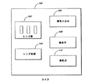
図1は、ズームレンズ102を伴うカメラ100のブロック図を例示している。ズームレンズは、焦点距離を変化させる能力を備えたレンズ素子の集合体である。個々のレンズ素子は、適所に固定されてよく、又はレンズボディに沿って軸方向に滑動してよい。レンズ群は、1つ又は2つ以上のレンズ素子で構成されてよい。少なくとも1つの可動レンズ群が、物体の倍率の変化を提供する。少なくとも1つのレンズ群が、倍率を達成するために移動するにつれ、焦点面の位置もまた、移動するであろう。焦点面の位置を一定に維持するために、少なくとも1つのその他の可動レンズ群が、焦点面の移動を補償するように移動されてよい。焦点面の移動に対する補償は、レンズの倍率の変化とともにレンズの集合体全体を移動させることによって、機械的に実現されてもよい。
Liquid Optics in Zoom Lens System FIG. 1 illustrates a block diagram of a
個々のレンズ素子は、ガラス材料、プラスチック材料、結晶質材料、若しくは半導体材料などの、固相材料で構成されてよく、又は水若しくは油などの、液体材料若しくは気体材料を使用して構成されてよい。レンズ素子間の空間は、1つ又は2つ以上の気体を内包していてよい。例えば、通常の空気、窒素、又はヘリウムが使用されてよい。あるいは、レンズ素子間の空間は、真空であってよい。本開示において「空気」という表現が使用されるときは、それが広義で使用され、1つ若しくは2つ以上の気体、又は真空を含みえるものと理解されるべきである。 Each lens element may be composed of a solid phase material, such as a glass material, plastic material, crystalline material, or semiconductor material, or constructed using a liquid or gaseous material, such as water or oil. Good. The space between the lens elements may contain one or more gases. For example, normal air, nitrogen, or helium may be used. Alternatively, the space between the lens elements may be a vacuum. Where the expression “air” is used in this disclosure, it should be understood that it is used broadly and may include one or more gases, or a vacuum.
ズームレンズは、ズーム機能及びピント合わせ機能を実現するために、3つ又は4つ以上の移動レンズ群を有することが多い。ズームを実施するために、機械的カムによって2つの可動レンズ群がリンクされてよく、ピント合わせには、第3の可動レンズ群が使用されてよい。 A zoom lens often has three or four or more moving lens groups in order to realize a zoom function and a focusing function. In order to perform zooming, two movable lens groups may be linked by a mechanical cam, and a third movable lens group may be used for focusing.
ズーム範囲は、一部には、可動レンズ素子の移動範囲によって決定される。ズーム範囲が広いほど、レンズ素子の移動のために更なる空間が必要となる。可動レンズ群の1つ又は2つ以上は、液体セル技術を採り入れたレンズ群に置き換えられてよい。液体セルは、軸方向移動のための空間を必要としないので、可動レンズ群を含むレンズ設計の長さは、短くされてよい。あるいは、可動レンズ群の軸方向移動のために使用されてきたであろう空間を、更なる光学素子や折り返しを含ませるために使用することができる。液体セルは、移動のための空間を必要としないが、可動レンズ群の一部であってよい。 The zoom range is determined in part by the moving range of the movable lens element. The wider the zoom range, the more space is required for movement of the lens elements. One or more of the movable lens groups may be replaced with a lens group that incorporates liquid cell technology. Since the liquid cell does not require space for axial movement, the length of the lens design including the movable lens group may be shortened. Alternatively, the space that would have been used for axial movement of the movable lens group can be used to include additional optical elements and folds. The liquid cell does not require a space for movement, but may be a part of the movable lens group.
液体セルは、ズーム及びピント合わせの両方に使用されてよい。一実施形態では、液体セル技術を採り入れたレンズ群とともに、可動レンズ群が使用される。可動レンズ群が1つである場合は、機械的カムは必要とされない。カムがないことは、更なる移動を可能にする。 The liquid cell may be used for both zooming and focusing. In one embodiment, a movable lens group is used with a lens group that employs liquid cell technology. If there is one movable lens group, no mechanical cam is required. The absence of a cam allows further movement.
ズーム及びピント合わせを実現するために、1つ又は2つ以上の液体セルとともに、1つ又は2つ以上の可動レンズ群が使用される。1つの可動レンズ群及び1つの液体セルによって、ズーム、ピント合わせ、及び熱的効果に対する補償の両方を実施することができる。一実装形態では、ズーム系は、少なくとも第1及び第2のレンズ群を有する。第1のレンズ群は、比較的高度数であり、第2のレンズ群は、比較的低度数であり、レンズの度数は、レンズの焦点距離の逆数に相当する。第1のレンズ群は、従来のガラスレンズ又はその他の固体レンズを含み、第2のレンズ群は、少なくとも1つの液体レンズを含む。 One or more movable lens groups are used with one or more liquid cells to achieve zooming and focusing. With one movable lens group and one liquid cell, both zooming, focusing and compensation for thermal effects can be implemented. In one implementation, the zoom system has at least first and second lens groups. The first lens group has a relatively high power, the second lens group has a relatively low power, and the power of the lens corresponds to the reciprocal of the focal length of the lens. The first lens group includes a conventional glass lens or other solid lens, and the second lens group includes at least one liquid lens.
液体セルは、レンズを形成するために、2つ又は3つ以上の液体を使用する。レンズの焦点距離は、一部には、液体間の接触の角度、及び液体の屈折率の差によって決定される。度数変化の範囲は、用いられる液体の屈折率の差、及び空間的制約ゆえに液体間の接触
表面における曲率半径の範囲が有限であることによって制限される。参照によって本明細書に組み込まれる米国特許出願公開第2006/0126190号は、エレクトロウェッティングを通じた液滴の変形を用いるレンズを開示している。
A liquid cell uses two or more liquids to form a lens. The focal length of the lens is determined in part by the angle of contact between the liquids and the difference in the refractive index of the liquids. The range of power change is limited by the difference in the refractive indices of the liquids used and the limited radius of curvature at the contact surface between the liquids due to spatial constraints. US Patent Application Publication No. 2006/0126190, incorporated herein by reference, discloses a lens that uses droplet deformation through electrowetting.
現在考えられる液体レンズ系は、少なくとも約0.2の、好ましくは少なくとも約0.3の、そして一部の実施形態では少なくとも約0.4の、屈折率の差を有する。水は、約1.3の屈折率を有し、塩の追加は、屈折率を約1.48に変化させられるであろう。適切な光学オイルは、少なくとも約1.5の屈折率を有するであろう。たとえ、例えばより高屈折率のオイルなど、より高屈折率の液体、より低屈折率の液体、又はより高屈折率の液体及びより低屈折率の液体を用いる場合でも、度数変化の範囲は、依然として有限である。この有限な度数変化の範囲は、通常、提供できる倍率変化が可動レンズ群よりも小さい。したがって、単純なズームレンズ系では、像面の位置を一定に維持しつつズームを提供するために、倍率変化の大半が1つの可動レンズ群によって提供され、倍率変化中の像面におけるピンぼけに対する補償の大半が1つの液体セルによって提供されるようにしてよい。ただし、より多くの可動レンズ群、又は液体セル、又はそれらの両方が用いられてよいことに、留意するべきである。 Currently contemplated liquid lens systems have a refractive index difference of at least about 0.2, preferably at least about 0.3, and in some embodiments at least about 0.4. Water has a refractive index of about 1.3 and the addition of salt will change the refractive index to about 1.48. A suitable optical oil will have a refractive index of at least about 1.5. Even when using higher refractive index liquids, lower refractive index liquids, or higher refractive index liquids and lower refractive index liquids, e.g. higher refractive index oils, the range of power change is Still finite. In the finite power change range, the magnification change that can be provided is usually smaller than that of the movable lens group. Therefore, in a simple zoom lens system, in order to provide zoom while maintaining the position of the image plane constant, most of the change in magnification is provided by one movable lens group, and compensation for defocus on the image plane during the change in magnification is provided. May be provided by a single liquid cell. However, it should be noted that more movable lens groups, liquid cells, or both may be used.
可動レンズ群は、正又は負の度数を有することができる。液体セルは、度数が常に正である、度数が常に負である、又は度数が正から負に若しくは負から正に移行するような、一定範囲の可変度数を有することができる。可動レンズ群及び液体セルの適切な配置構成は、ズーム範囲全体にわたって優れた画質を提供しつつ、2倍より大きい、好ましくは3倍より大きい拡張されたズーム比を提供する。この配置構成は、液体セル、可動レンズ群、又はそれらの両方によって更に可能になる度数の変化を用いることによって、ズームだけでなく、拡張された合焦範囲にわたって異なる物体距離におけるピント合わせを提供してもよい。液体セル、又は可動レンズ群、又はそれらの両方によって提供される、ピント合わせのためのこの更なる度数の変化は、容易に可能である。可動レンズ群が1つである場合は、移動軌道を固定されたカムが必ずしも必要とされないので、可動ズームレンズ群の位置は、ズーム及びピント合わせのために調整することができる。ズーム及びピント合わせのために、可動ズームレンズ群及び液体セルの両方を用いることによって、高性能の撮像が実現される。 The movable lens group can have a positive or negative power. The liquid cell can have a range of variable powers such that the power is always positive, the power is always negative, or the power transitions from positive to negative or from negative to positive. Proper arrangement of the movable lens group and the liquid cell provides an extended zoom ratio that is greater than 2x, preferably greater than 3x, while providing excellent image quality over the entire zoom range. This arrangement provides focusing at different object distances over an extended focus range, as well as zoom, by using power changes that are further enabled by the liquid cell, the movable lens group, or both. May be. This further power change for focusing provided by the liquid cell or the movable lens group or both is readily possible. When there is one movable lens group, a cam with a fixed movement trajectory is not necessarily required, so the position of the movable zoom lens group can be adjusted for zooming and focusing. By using both the movable zoom lens group and the liquid cell for zooming and focusing, high-performance imaging is realized.
また、可動ズームレンズ群を、少なくとも1つの液体セルで置き換えることも可能である。これは、光学系の複雑性を増加させ、倍率変化の減少などのその他の不利点をもたらす可能性がある。 It is also possible to replace the movable zoom lens group with at least one liquid cell. This increases the complexity of the optical system and can lead to other disadvantages such as reduced magnification changes.
図1は、レンズ102内のレンズ群の移動及び動作を制御するレンズ制御モジュール104も例示している。制御モジュール104は、液体レンズセル内の曲率半径を制御する電子回路系を含む。電子回路系は、可動レンズ群の位置も制御してよい。様々な合焦位置及びズーム位置に対応する適切な電子信号レベルを事前に決定し、ルックアップテーブルに配することができる。あるいは、アナログ回路系によって、又は回路系とルックアップテーブルとの組み合わせによって、適切な信号レベルを生成することができる。一実施形態では、適切な電子信号レベルを決定するために、多項式が使用される。多項式に沿った点をルックアップテーブルに保存することができる、又は回路系によって多項式を実行することができる。
FIG. 1 also illustrates a
液体間表面の曲率半径、又は可動レンズ群の位置、又はそれらの両方を制御するにあたり、熱的効果も考慮されてよい。多項式又はルックアップテーブルは、熱的効果に関連した更なる変数を含んでいてよい。 In controlling the radius of curvature of the inter-liquid surface and / or the position of the movable lens group, thermal effects may also be considered. The polynomial or lookup table may contain additional variables related to thermal effects.
制御モジュール104は、特定のズーム設定又は焦点距離に対する事前制御を含んでい
てよい。これらの設定は、ユーザ又はカメラのメーカによって保存されてよい。
The
図1は、更に、外部物体に対応する光学像を受信する像取り込みモジュール106を例示している。像は、光軸に沿ってレンズ102を通して像取り込みモジュール106に送られる。像取り込みモジュール106は、フィルム(例えばフィルムストック若しくは静止画フィルム)、又は電子的像検出技術(例えばCCDアレイ、CMOSデバイス、若しくはビデオピックアップ回路)などの、様々なフォーマットを使用してよい。光軸は、直線であってよく、又は折り返し若しくは放射軸のその他の方向変更を含んでよい。なお、本明細書において使用される折り返しという表現は、広義の解釈を意図しているものと理解されるべきである。放射軸の方向変更は、様々な光学素子によって可能であり、本発明の範囲は、特定のタイプの光学素子に限定されるべきでない。
FIG. 1 further illustrates an
像保存モジュール108は、取り込まれた像を、例えば、オンボードメモリに、又はフィルム、テープ、若しくはディスクに保持する。一実施形態では、保存媒体は、取り外し式(例えばフラッシュメモリ、フィルム容器、テープカートリッジ、又はディスク)である。
The
像転送モジュール110は、取り込まれた像を、その他のデバイスに転送する。例えば、像転送モジュール110は、USBポート、IEEE 1394マルチメディア接続、Ethernetポート、Bluetoothワイヤレス接続、IEEE 802.11ワイヤレス接続、ビデオコンポーネント接続、又はS−Video接続などの、様々な接続の1つを使用してよい。
The
カメラ100は、ビデオカメラ、携帯電話カメラ、デジタル写真用カメラ、又はフィルムカメラなどの、様々な形態で実装されてよい。
The
次に、設計例によって、ズームレンズの一実施形態が説明される。先ず、図2を参照すると、各レンズ素子は、文字「E」に1から20までの数字を付して特定され、図では、各レンズ素子の一般的構成が示されているが、各レンズ表面の実際の半径は、以下において、テーブル1に定められている。レンズ、物体、絞り又はアイリス、及び像表面は、1から36までの数字によって特定される。3つのレンズ群は、図2において、文字「G」に1から3までの数字を付して特定され、液体レンズセルは、文字「LC」によって特定され、19から23までの光学表面を含む。光軸は、図2において、数字38によって特定される。 Next, an embodiment of the zoom lens will be described by design examples. First, referring to FIG. 2, each lens element is identified by adding a number from 1 to 20 to the letter “E”, and the general configuration of each lens element is shown in the figure. The actual radius of the surface is defined in Table 1 below. Lenses, objects, apertures or irises, and image surfaces are identified by numbers from 1 to 36. The three lens groups are identified in FIG. 2 with the letter “G” appended with a number from 1 to 3, and the liquid lens cell is identified by the letter “LC” and includes optical surfaces from 19 to 23. . The optical axis is identified by numeral 38 in FIG.
各レンズ素子は、その相対する表面を、別々の、しかしながら連続した表面番号によって特定され、例えば、図2に示されるように、レンズ素子E1は、レンズ表面2、3を有し、レンズ素子E9は、レンズ表面17、18を有し、以下同様である。撮像対象物体の場所は、特にそれが合焦距離に関連するゆえに、光軸38上の縦線及び数字1によって特定され、実像表面は、数字36によって特定される。レンズ表面4、8を除く全てのレンズ表面は、球面又は平面であり、レンズ表面4、8は、球面でも平面でもないが、光軸まわりに回転対称な非球面である。
Each lens element has its opposite surface identified by a separate but sequential surface number, for example, as shown in FIG. 2, lens element E1 has lens surfaces 2, 3 and lens element E9. Has lens surfaces 17, 18 and so on. The location of the object to be imaged is specified by the vertical line on the
レンズ素子の詳細な特性を説明する前に、ズームレンズ系60について、レンズ群とそれらの軸方向の位置及び移動、並びに液体レンズセルとその接触液体の表面形状の変化が大まかに説明される。
Before describing the detailed characteristics of the lens elements, the
各レンズ群の正又は負の度数は、焦点距離の逆数として定義される。結果得られる各レンズ群の光学的度数は、以下の通りである。すなわち、対物レンズ群G1は正であり、ズームレンズ群G2は負であり、後方レンズ群G3は正であって、液体セル内の表面形状の
変化に伴って低い正の値から高い正の値まで変化する。図2の上方部分にある双頭の水平矢印は、ズームレンズ群G2が両方の軸方向に可動であることを示している。
The positive or negative power of each lens group is defined as the reciprocal of the focal length. The resulting optical power of each lens group is as follows. That is, the objective lens group G1 is positive, the zoom lens group G2 is negative, the rear lens group G3 is positive, and the positive value increases from a low positive value as the surface shape in the liquid cell changes. Change to. A double-headed horizontal arrow in the upper part of FIG. 2 indicates that the zoom lens group G2 is movable in both axial directions.
図2には、レンズ素子のみが物理的に示されているが、レンズケース内又は鏡筒内においてレンズ素子を支えるため及び可動ズームレンズ群を軸方向に移動させるために、機械的なデバイス及びメカニズムが提供されることが、理解されるべきである。また、電子回路系が、液体レンズセル内の可変的に形成された光学表面のプロフィールを変化させることが、理解されるべきである。 In FIG. 2, only the lens element is physically shown. However, in order to support the lens element in the lens case or the lens barrel and to move the movable zoom lens group in the axial direction, mechanical devices and It should be understood that a mechanism is provided. It should also be understood that the electronic circuitry changes the profile of the variably formed optical surface within the liquid lens cell.
上述されたズームレンズ系60のレンズの構成データ及び製造データが、以下において、テーブル1に定められている。テーブル1のデータは、摂氏25度(華氏77度)の温度及び標準大気圧(760mmHg)で与えられる。この明細書全体を通して、測定値は、波長がナノメートル(nm)で表されることを除き、ミリメートル(mm)で表されるものとする。テーブル1において、第1の欄「項目」は、各光学素子、及び対物面や像面などの各場所を、図2において使用されたのと同じ数字又は標識で特定している。第2の欄は、光学素子(レンズ)が所属する「群」を、図2において使用されたのと同じ数字で特定している。第3の欄「表面」は、図2に示された、物体(図2における線「1」及びテーブル1における「物体」)の表面番号、絞り(アイリス)13、並びにレンズの各実表面を挙げたものである。第4の欄「合焦位置」は、ズームレンズ系60における3つの代表的合焦位置(F1、F2、及びF3)を特定しており、より詳しく後ほど説明されるように、第3の欄に列挙された一部の表面の間の距離(間隔)及び第3の欄に挙げられた表面21の曲率半径には変化が生じる。第5の欄「間隔」は、その表面(第3の欄)と次の表面との間の軸方向距離である。例えば、表面S2と表面S3との間の距離は、1.725mmである。
The lens configuration data and manufacturing data of the
「曲率半径」という見出しを付けられた第6の欄は、各表面について光学表面の曲率半径を挙げたものであり、マイナス符号(−)は、曲率半径の中心が図2で見て表面の左であることを意味し、「無限遠」は、光学的に平坦な表面を意味する。表面4、8に対する星印(*)は、これらが、「曲率半径」を底面半径とする非球面であることを示している。非球面の使用は、全体サイズの小型化及び構成の単純化を可能にしつつ、ズームレンズにおける収差の補正を提供する。非球面4、8の表面プロフィールについての式及び係数は、以下の方程式に支配される。

c=表面曲率(c=1/rで、rは曲率半径である)であり、
y=X軸及びY軸から測定された表面の半径方向開口高さであって、
y=(X2+Y2)1/2であり、
κ=円錐係数であり、
A、B、C、D、E、F=それぞれ4次、6次、8次、10次、12次、及び14次の変形係数であり、
z=所定のy値の場合の表面プロフィールの位置、又は表面の極(すなわち軸方向頂点)から光軸に沿って測定された表面プロフィールの位置である。
表面4についての係数は、
κ=−0.6372
A=+0.9038x10⁻⁶
B=+0.2657x10⁻⁸
C=−0.1105x10⁻¹⁰
D=+0.4301x10⁻¹³
E=−0.8236x10⁻¹⁶
F=+0.6368x10⁻¹⁹ である。
表面8についての係数は、
κ=+0.0000
A=+0.5886x10⁻⁴
B=−0.5899x10⁻⁶
C=+0.8635x10⁻⁸
D=−0.5189x10⁻¹⁰
E=−0.1186x10⁻¹¹
F=+0.1631x10⁻¹³ である。
The sixth column headed “Curve Radius” lists the radius of curvature of the optical surface for each surface, and the minus sign (−) indicates the center of curvature radius of the surface as seen in FIG. It means left and “infinity” means an optically flat surface. The asterisks (*) for the
c = surface curvature (c = 1 / r, r is the radius of curvature);
y = radial opening height of the surface measured from the X and Y axes,
y = (X 2 + Y 2 ) 1/2
κ = conic coefficient,
A, B, C, D, E, F = fourth, sixth, eighth, tenth, twelfth and fourteenth deformation coefficients, respectively.
z = the position of the surface profile for a given y value, or the position of the surface profile measured along the optical axis from the surface pole (ie, axial vertex).
The coefficient for surface 4 is
κ = −0.6372
A = + 0.9038 × 10 −6
B = + 0.2657 × 10 −8
C = −0.1105 × 10 −10
D = + 0.4301 × 10 −13
E = -0.8236x10 -16
F = + 0.6368 × 10 −19 .
The coefficient for
κ = + 0.0000
A = + 0.5886 × 10 −4
B = −0.5899 × 10 −6
C = + 0.8635x10 -8
D = −0.5189 × 10 −10
E = −0.1186 × 10 −11
F = + 0.1631 × 10 −13 .
テーブル1の第7欄から第9欄までは、その表面(第3の欄)と、図2において右隣りの次の表面との間の「材料」に関するものであり、「タイプ」欄は、これらの2つの表面間にあるのがレンズ(ガラス)であるか、又は何もない空間(空気)であるか、又は液体レンズ(液体)であるかを示している。ガラスレンズ及び液体レンズは、「コード」欄の光学ガラス又は液体によって特定される。便宜上、全てのレンズガラスは、株式会社オハラ(Ohara Corporation)より入手可能なガラスから選択され、「名前」欄には、オハラによる各ガラスタイプの識別番号が挙げられている。ただし、等価な、類似の、又は適切な任意のガラスが使用されてよいことが、理解されるべきである。また、オイルのレンズ液は、カーギル研究所(Cargille Laboratories, Inc.)より入手可能な液体から選択され、水は、様々なソースより手近に入手可能である。ただし、等価な、類似の、又は適切な任意の液体が使用されてよいことが、理解されるべきである。表面20における液体である水は、656.27nm、589.29nm、546.07nm、及び486.13nmの波長において、それぞれ1.331152、1.332987、1.334468、及び1.337129の屈折率を有する。表面21における液体であるオイルは、656.27nm、589.29nm、546.07nm、及び486.13nmの波長において、それぞれ1.511501、1.515000、1.518002、及び1.523796の屈折率を有する。
「口径」という見出しを付されたテーブル1の最後の欄は、各表面について、光線が通り抜ける最大直径を提供している。絞り表面13を除き、全ての最大口径は、全てのズーム位置及び合焦位置において、像面における最大像直径が6mmで且つF値がF/2.8からF/4.0である場合に546.1nmの波長で与えられる。テーブル1において、絞り表面13の最大口径は、ズーム位置Z1及び合焦位置F1において、像面におけるF値がF/2.8である場合に546.1nmの波長で与えられる。像面36では、最大口径は、近似値として与えられる。
The last column of Table 1 with the heading “Aperture” provides for each surface the maximum diameter through which the rays pass. Except for the stop surface 13, all the maximum apertures are obtained when the maximum image diameter on the image plane is 6 mm and the F value is F / 2.8 to F / 4.0 at all zoom positions and in-focus positions. Given at a wavelength of 546.1 nm. In Table 1, the maximum aperture of the aperture surface 13 is given at a wavelength of 546.1 nm when the F value on the image plane is F / 2.8 at the zoom position Z1 and the focus position F1. In the
ズームレンズ系60は、表面13に、光線が通り抜けできるその地点における開口の直径を制御する光絞りを提供される。光絞りは、物理的なアイリス(ダイヤフラム)を配される場所である。アイリスは、後方レンズ群G3の前に配され、そのレンズ群に対して軸方向に固定される。なお、図4Aにおいては、ズームレンズ系が、いかなる視野位置、ズーム位置、及び合焦位置においても光ビームのけられを有することがないように、縁の光線は、光絞り表面13の目盛りマークよりも軸側を通り抜ける。ただし、F値がズーム位置及び合焦位置を通して変化すること、並びにそれに応じてアイリスが開いたり閉じたりすることに留意せよ。合焦位置F1の場合、ズーム位置Z1〜Z8におけるアイリスの直
径は、6.71、6.39、5.96、5.53、5.18、4.84、4.63、及び4.61である。これは、13に配されたアイリスが、焦点距離が長くなるほど絞られることを示している。合焦位置F1と比較すると、合焦位置F2及びF3の場合のズーム位置Z1〜Z8におけるアイリスの直径は、合焦位置F1の場合と同じF値を維持するために、直径0.3mm未満の少量だけ変化する。
The
テーブル1を参照すると、設計の範囲及び汎用性を示するために、8つの異なるズーム位置Z1、Z2、Z3、Z4、Z5、Z6、Z7、及びZ8と、3つの異なる合焦位置F1、F2、及びF3とがデータとして定められ、これは、実際、可動ズームレンズ群G2及び可変形状光学表面21の24(8×3=24)の異なる位置組み合わせについて、具体的なデータを提供している。
Referring to Table 1, eight different zoom positions Z1, Z2, Z3, Z4, Z5, Z6, Z7, and Z8 and three different in-focus positions F1, F2 are shown to show the range of design and versatility. , And F3 are defined as data, which actually provides specific data for 24 (8 × 3 = 24) different positional combinations of the movable zoom lens group G2 and the deformable
合焦位置F1において、ズーム位置Z1〜Z8の場合のズームレンズ系60の焦点距離は、波長546.1nmにおいて、それぞれ5.89mm、7.50mm、11.25mm、15.00mm、18.75mm、30.00mm、41.25mm、及び45.00mmである。データ位置Z1〜Z8の場合の焦点距離に対応するF値は、波長546.1nmにおいて、それぞれ2.80、2.90、3.05、3.25、3.45、3.70、3.95、及び4.00である。
At the in-focus position F1, the focal length of the
合焦位置F1の場合は、対物面1は、無限遠にあると想定され、合焦位置F2の場合は、対物面1は、約1016.25mmの中間距離にあり、合焦位置F3の場合は、対物面1は、約378.75mmの近距離にある(すなわち像面から378.75mm離れている)。これら3つの合焦位置F1、F2、及びF3のそれぞれにおいて、レンズ群G1及びG3は、ズームレンズ群G2の移動範囲全体を通して同じ位置にとどまる。テーブル2及びテーブル3は、表面7及び12の間隔値を提供しており、テーブル4は、ズーム位置Z1〜Z8及び合焦位置F1〜F3の場合の表面21の曲率半径を提供している。
In the case of the in-focus position F1, it is assumed that the
両極の合焦位置F1とF3の間において連続的なピント合わせが可能であること、両極のズーム位置Z1とZ8との間において連続的なズームが可能であること、そしてレンズ系60によって、説明された合焦範囲内及びズーム範囲内において連続的なピント合わせと連続的なズームとを任意に組み合わせて提供可能であることが理解される。
The fact that continuous focusing is possible between the in-focus positions F1 and F3, that continuous zooming is possible between the zoom positions Z1 and Z8, and the
図2に示されテーブル1に規定されたズームレンズ系60は、レンズ群G1及びG2について、それぞれ54.30mm及び−12.25mmの焦点距離を有する。また、レンズ群G3は、液体間の光学表面21の形状が可変であるゆえに、ズーム位置Z1及び合焦位置F1における最小値+30.18mmと、ズーム位置Z8及び合焦位置F3における最大値+38.97mmとを有する可変焦点距離を有する。ズームレンズ系60の液体セルLCは、図3A及び図3Bに図示されており、これらの図は、テーブル1をもとに、形状が可変である液体間光学表面21の2つの両極端な曲率半径を示している。図3A及び図3Bにおいて、表面21の2つの曲率半径は、それぞれ約−33.99mm及び約+115.80mmである。図3A及び図3Bにおいて、液体セルLCの2つの両極端な焦点距離は、それぞれ−185.20mm及び630.97mmである。この差は、ズーム位置Z1及び合焦位置F1と、ズーム位置Z8及び合焦位置F3とで生じる。この実施形態では、表面20と21との間及び表面21と22との間の2つの液体の体積は、可変表面の形状が変化するにつれて変わっていく。しかしながら、表面20と21との間及び表面21と22との間の軸方向間隔に、等しいが方向が反対の小さな変化を加えることによって、各液体を一定の体積に維持することも可能である。
The
次に、図4A、図4B、及び図4Cを参照すると、様々な位置にあるズームレンズ群と、様々な位置にある液体セル内可変表面形状とを伴うズームレンズ系60が、それらの位置における光線の軌跡とともに図示されている。図4Aは、テーブル1にデータを定めら
れた、無限遠焦点及び約5.9mmの短焦点距離を伴う合焦位置F1及びズーム位置Z1を表している。図4Bは、テーブル1により、中間焦点及び約11.3mmの焦点距離を伴う合焦位置F2及びズーム位置Z3を表している。図4Cは、テーブル1により、近距離焦点及び約44.8mmの焦点距離を伴う合焦位置F3及びズーム位置Z8を表している。
Referring now to FIGS. 4A, 4B, and 4C, a
図4A、図4B、及び図4Cは、それぞれのズーム位置及び合焦位置であるZ1及びF1、Z3及びF2、Z8及びF3について、ズームレンズ群G2の3つの軸方向場所を、対応する3つの可変光学表面21表面形状とともに示している。
4A, 4B, and 4C show three corresponding axial positions of the zoom lens group G2 for Z1 and F1, Z3 and F2, and Z8 and F3, which are the zoom position and the focus position, respectively. The variable
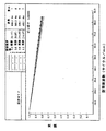
ズームレンズ系60の光学性能が、図5A、図5B、及び図5Cに与えられており、テーブル1に定められた3つの異なる代表的組み合わせ例のズーム位置及び合焦位置、すなわち(Z1,F1)、(Z3,F2)、及び(Z8,F3)における、5つの異なる視野位置について、回折ベースの多色変調伝達関数(「MTF」)データ(変調対空間周波数)がパーセント(%)で表示されている。視野位置は、正規化された像高さ(mm)及び光軸からの実際の物体空間角度(度)の両値として定められる。MTFパーセントは、図5A、図5B、及び図5Cの右上隅に定められた波長及び重み付けにおけるものであり、像面36における接線(T)方向及び半径(R)方向の測定をグラフ表示されている。なお、接線方向の値及び半径方向の値が軸方向視野位置(AXIS)では等しいこと、並びにそれゆえに1つの線だけで示されていることに留意せよ。示されている最大空間周波数は、90サイクル/mmであり、これは、約6mmの像直径及び検出器画素サイズの選択を前提としたときに、少なくとも高精細度テレビ(HDTV)の解像度すなわち横1920画素×縦1080画素で高品質の像を提供することができる。空間周波数におけるMTFは、比較的標準的な光学性能測定であり、「90サイクル/mm」という値は、鮮明さを判断するもととなるチャート上における1mmあたり90対の黒線及び白線を意味している。最高MTF値は、ズーム位置Z1及び合焦位置F2の場合の全半径方向視野における約89%である。最低MTF値は、ズーム位置Z8及び合焦位置F3の場合の全接線方向視野における約58%である。最小相対照度は、ズーム位置Z1及び合焦位置F1における約75%である。相対照度は、値が低いとその写真の隅で光が衰えることを意味するので、総じて高いほど優れている。全ての領域において光に対して一定の応答があり、ズーム中の像の変化に伴って像の隅に忠実に陰影を再現する最先端の検出器では、高い全視野相対照度が好ましいとされる。50%未満の照度は、電子的検出器において陰影を生じるが、フィルム式の場合は許容可能である可能性がある。最も高い正のゆがみは、ズーム位置Z3及び合焦位置F1における+3.04%であり、最も低い負のゆがみは、ズーム位置Z1及び合焦位置F3における−2.98%である。遠距離焦点から近距離焦点にかけて像のサイズが変化する一般的な(しかしながらズームレンズではもっとよく見られるであろう)いわゆるレンズの「ブリージング」の問題は、深い被写界深度ゆえに最も顕著である短焦点距離のズーム範囲にあるズームレンズ系60では事実上見られない。最も低いブリージングは、ズーム位置Z1及び合焦位置F3における−0.2%であり、最も高いブリージングは、ズーム位置Z8及び合焦位置F3における−19.5%である。ブリージングは、無限遠焦点から被選択焦点にかけての最大画角のパーセント変化である。したがって、無限遠焦点(F1)では、それが基準視野であるゆえに、ブリージングはゼロである。
The optical performance of the
全ての性能データは、摂氏25度(華氏77度)の温度、標準大気圧(760mmHg)、及びズームレンズ系60において可能な全開絞りで与えられる。しかしながら、ズームレンズ系60は、摂氏0度から摂氏40度(華氏32度から華氏104度)の温度範囲にわたって実質的に一定の例えばMTF値などの性能を提供するものであり、もし性能(MTF)の僅かな低下が許容可能であるならば、動作可能な温度範囲を摂氏−10度から摂氏50度(華氏14度から華氏122度)まで、又はそれを超えて拡張することができ
る。温度変化に対しては、ズームレンズ群G2の更なる軸方向調整によって、又は接触光学表面21の更なる形状変化によって、又はそれら両方の組み合わせによって、最適な性能が達成されてよい。これは、全てのズーム位置及び合焦位置において生じえる。摂氏約0度(華氏32度)又はそれ未満の低温では、凍結(固形化)を回避するために、液体を加熱する、又は低温動作用に車のラジエータの水に不凍剤を加えるのと同様の方法で液体をドープ液で置き換える必要があると考えられる。ただし、これらの材料の温度変化は、液体の光学特性を大幅に変更するべきではないことが好ましい。
All performance data is given at a temperature of 25 degrees Celsius (77 degrees Fahrenheit), standard atmospheric pressure (760 mmHg), and fully open aperture possible in the
ズームレンズ系60を使用している上述の実施形態は、6mmの直径(いわゆる3分の1インチチップセンサ)での使用に適した寸法であるが、このズームレンズ系の寸法は、様々な像フォーマットのフィルム及び電子的検出器での使用のために、適切に拡大又は縮小されてよい。
While the above-described embodiments using the
液体レンズセルは、有限の口径を有してよい。もし充分に小さい検出器が使用されるならば、液体レンズセルは、その検出器の近くに配されてよい。あるいは、液体レンズセルは、光線「くびれ」が充分に狭くなる中間像の近くに配されてよい。液体レンズセルは、中間像の前、中間像の後、又は中間像の前及び後の両方に配されてよい。くびれ効果は、絞り又はアイリスの近くで発生することができる。テーブル2に示されるように、アイリスにおける直径は、おおよそ6.7mmである。絞り又はアイリスにおける直径が小さいゆえに、液体レンズセルは、絞り又はアイリスの付近に配することが適切であると考えられる。 The liquid lens cell may have a finite aperture. If a sufficiently small detector is used, the liquid lens cell may be placed close to the detector. Alternatively, the liquid lens cell may be placed near an intermediate image where the beam “necking” is sufficiently narrow. The liquid lens cell may be placed before the intermediate image, after the intermediate image, or both before and after the intermediate image. The necking effect can occur near the iris or iris. As shown in Table 2, the diameter at the iris is approximately 6.7 mm. Due to the small diameter of the iris or iris, it may be appropriate to place the liquid lens cell in the vicinity of the iris or iris.
ズームレンズ系60の多くの利点のなかで特筆すべきは、軸方向に移動するズームレンズ群を1つ用いるだけで、広範囲の焦点距離にわたってズームを提供できることにある。ズームレンズ系60の設計は、少なくとも2つの軸方向可動ズームレンズ群及びそれらに対応する機構を必要とする大半の従来の高性能ズームレンズ系よりも機械的に単純な高性能なレンズ系を形成する。ズームレンズ系60の固有なレンズ設計は、更なる可動レンズ群及びそれに対応する機構を伴うことなく広範囲の合焦距離にわたってピント合わせを提供する。開示されたズームレンズ系60の設計は、例示的なものであり、その他の設計も、本発明の範囲内である。当業者ならば、以上の説明及び添付の図面から、ズームレンズ系60のその他の特徴及び利点を見てとることができる。
Among the many advantages of the
ズームレンズ系における液体光学及び放射軸の方向変更
液体レンズセルによる1つ又は2つ以上の移動レンズ群の置き換えは、光路の構成に対して更なる選択肢を可能にする。液体レンズセルによる移動レンズ群の置き換えは、レンズ系をよりコンパクトにする。しかしながら、直線状の光学設計は、レンズを所望よりも長くするであろう。移動レンズ群に代わる液体レンズセルの使用は、放射軸の方向を変えてレンズの物理的長さを短くするための折り返しなどの光学素子の使用を容易にする。レンズを通る光路の全長は、同じままであるが、液体レンズセルは、長さを1つ又は2つ以上の方向に短くする折り返しのための戦略的空間を提供する。これは、より小さいカメラケース内における、より長いレンズ全長の使用を可能にする。例えば、多くのポイント及びシュートカメラや携帯電話カメラは、長焦点レンズのための大きな空間を有していない。折り返しと組み合わせて液体セルを使用することによって、これらの小型のカメラケース内において、より優れたレンズ系が利用可能になる。より大型のカメラも、やはり、折り返しを使用しなかったレンズ系において必要とされるであろうよりもカメラケースの長さが短くなることによる恩恵を受ける。
Replacing one or more moving lens groups with liquid optical and radial axis redirection liquid lens cells in a zoom lens system allows further options for the configuration of the optical path. Replacing the moving lens group with a liquid lens cell makes the lens system more compact. However, a linear optical design will make the lens longer than desired. The use of a liquid lens cell instead of a moving lens group facilitates the use of optical elements such as folding to change the direction of the radial axis and shorten the physical length of the lens. The total length of the optical path through the lens remains the same, but the liquid lens cell provides a strategic space for folding that shortens the length in one or more directions. This allows the use of longer lens lengths in smaller camera cases. For example, many point and shoot cameras and cell phone cameras do not have a large space for long focus lenses. By using a liquid cell in combination with folding, a better lens system can be used in these small camera cases. Larger cameras still benefit from a shorter camera case length than would be required in a lens system that did not use folding.
図6は、液体及び単一の折り返し41を用いるズームレンズ系の光学図を示している。可動レンズ群に代わる液体の使用は、空間要求を減らし、折り返しミラー又はプリズムのための空域の戦略的配置に対して更なる選択肢を可能にする。この図は、可動レンズ群を
妨げない場所に折り返しを配置することを示している。
FIG. 6 shows an optical diagram of a zoom lens system using liquid and a single fold 41. The use of liquids instead of movable lens groups reduces space requirements and allows further options for the strategic placement of airspace for folding mirrors or prisms. This figure shows that the fold is arranged at a place where the movable lens group is not obstructed.
ズームレンズ系60の全長の短縮は、より多くのレンズ素子及び/又は非球面を導入するなどによって光学的複雑性を増大させない限り、幾らかの性能低下を伴うであろう。しかしながら、長さの短縮は、ズームレンズ系の折り返しによって実現することができる。図6は、放射経路の方向を90度変えるための、後方レンズ群G3内の大きい空域内にある単一の45度の折り返し41を示している。
The shortening of the overall length of the
図7は、液体及び二重の折り返しを用いるズームレンズ系の光学図である。図7は、放射が逆方向を有するように放射経路の方向を2度にわたって合計180度変えるための、後方レンズ群G2内の大きな空域内にある二重の45度の折り返し42、43を示している。この配置構成は、ズームレンズ系60をカメラボックス内に実装するのに好ましいであろう。また、ズームレンズ系は、全てのズーム位置及び合焦位置を通して一定の絞りF/2.8を有してよいが、ズームレンズ系の直径をほぼ同じに維持するには、幾らかのけられを生じることがある。この場合は、幾らかの画質低下が見られることがあるが、これは、ズームレンズ系の規定を最適化しなおすことによって部分的に補正することが可能である。ズームレンズ系は、けられが生じないように配置構成することが可能である。
FIG. 7 is an optical diagram of a zoom lens system using liquid and double folding. FIG. 7 shows double 45 degree folds 42, 43 in a large airspace in the rear lens group G2 to change the direction of the radiation path over a total of 180 degrees so that the radiation has the opposite direction. ing. This arrangement may be preferable for mounting the
図8A及び図8Bは、ズームレンズ系の光学図であり、放射軸の方向変更を、異なるズームレンズ群位置及び液体間表面形状とともに例示している。この実施形態は、代替のレンズ配置を描いたものである。図8Aは、光学的軌跡がレンズ系のパラメータを超える点まで像を拡大するズーム位置を例示している。この実施形態は、設計の一選択肢を描いたものであり、この効果を補正するために、設計に僅かな変更を加えることが可能である。 FIG. 8A and FIG. 8B are optical diagrams of the zoom lens system, and illustrate a change in the direction of the radial axis together with different zoom lens group positions and inter-liquid surface shapes. This embodiment depicts an alternative lens arrangement. FIG. 8A illustrates the zoom position where the image is magnified to a point where the optical trajectory exceeds the parameters of the lens system. This embodiment depicts one design option, and slight modifications can be made to the design to compensate for this effect.
折り返し44及び45は、実質的に平行であるので、レンズ素子50から去っていく光線は、レンズ46を通してレンズ系に入ってくる光線に実質的に平行である。レンズ群47が固定されたままである間に、レンズ群48は、充分にズームを提供するために移動する。レンズ群49は、ズーム機能及びピント合わせ機能を実施する液体レンズセルを含む。
Since the
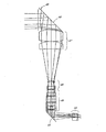
図9A、図9B、及び図9Cは、ズームレンズ系の光学図であり、レンズ系の長さを有利に短くするために、液体レンズセル及び折り返しが戦略的に配置されている。光は、レンズ群200を通してレンズ系に入る。レンズ群201は、充分にズームを提供するために移動する。光線は、アイリス又は絞り202を通り抜け、液体レンズセルを含むレンズ群203に入る。折り返し204は、レンズ群205を通るように光を方向付け、このレンズ群205は、可変な表面206を有する液体レンズセルを含む。光線は、次いで、レンズ群207を通り抜ける。折り返し208は、レンズ群209を通って像面210に向かうように光線の方向を変える。図9Aは、おおよそ6mmの焦点距離、F2.8、及び無限遠焦点を例示している。図9Bは、おおよそ15mmの焦点距離、F2.8、及び無限遠焦点を例示している。図9Cは、おおよそ51mmの焦点距離、F2.8、及び無限遠焦点を例示している。
FIGS. 9A, 9B, and 9C are optical diagrams of the zoom lens system, in which liquid lens cells and folds are strategically arranged to advantageously shorten the length of the lens system. Light enters the lens system through the
レンズ群203内の第1の液体レンズセルは、おおよそ10mmの最大口径を有する。レンズ群205内の第2の液体レンズセルは、おおよそ16mmの最大口径を有する。カメラフラッシュを含ませて、長焦点距離又はそれに近い焦点距離における絞り調整を遅くすれば、1つの液体レンズセルに戻すことも可能であろう。
The first liquid lens cell in the
当業者にならば、様々な変更及び修正が明らかになる。このような変更及び修正は、添付の特許請求の範囲に定められた本発明の範囲内に含まれるものとして理解されるべきである。 Various changes and modifications will become apparent to those skilled in the art. Such changes and modifications are to be understood as being included within the scope of the present invention as defined by the appended claims.
Claims (8)
軸方向に可動なズームレンズ群と、
少なくとも1つの液体レンズセルを含む軸方向に固定されたレンズ群であって、前記少なくとも1つの液体レンズセルは、第1及び第2の接触液体を含み、前記接触液体間の接触光学表面は、可変な形状を有する、軸方向に固定されたレンズ群と、
放射軸の方向を変える光学素子と、
を備え、
前記軸方向に可動なズームレンズ群及び前記軸方向に固定されたレンズ群は、共通の光軸上に並べられ、前記ズームレンズ系の物体側空間から発せられる放射を集めて前記放射を像側空間に送るように配置構成される、ズームレンズ系。 A zoom lens system,
A zoom lens group movable in the axial direction;
An axially fixed lens group including at least one liquid lens cell, wherein the at least one liquid lens cell includes first and second contact liquids, and the contact optical surface between the contact liquids is: A lens group having a variable shape and fixed in the axial direction;
An optical element that changes the direction of the radiation axis;
With
The zoom lens group movable in the axial direction and the lens group fixed in the axial direction are arranged on a common optical axis, and collect the radiation emitted from the object side space of the zoom lens system so that the radiation is image-side. A zoom lens system configured to be sent to space.
前記放射軸の方向を変える前記光学素子は、ミラーを含む、ズームレンズ系。 The zoom lens system according to claim 1,
The zoom lens system, wherein the optical element that changes the direction of the radiation axis includes a mirror.
前記放射軸の方向を変える前記光学素子は、プリズムを含む、ズームレンズ系。 The zoom lens system according to claim 1,
The zoom lens system, wherein the optical element that changes the direction of the radiation axis includes a prism.
可動レンズ群と、
液体セルレンズ群と、
放射軸の方向を変える光学素子と、
を備えるズームレンズ系。 A zoom lens system,
A movable lens group;
A liquid cell lens group;
An optical element that changes the direction of the radiation axis;
Zoom lens system with
前記可動レンズ群、前記液体セルレンズ群、及び前記放射軸の方向を変える前記光学素子は、共通の光軸上に並べられる、ズームレンズ系。 The zoom lens system according to claim 4,
The zoom lens system, wherein the movable lens group, the liquid cell lens group, and the optical element that changes the direction of the radiation axis are arranged on a common optical axis.
可動レンズ群、液体セルレンズ群、及び放射軸の方向を変える光学素子を含むズームレンズと、
前記ズームレンズ系の焦点場所に配置された像取り込み素子と、
を備えるカメラシステム。 A camera system,
A zoom lens including a movable lens group, a liquid cell lens group, and an optical element that changes the direction of the radiation axis;
An image capturing element disposed at a focal point of the zoom lens system;
A camera system comprising:
前記像取り込み素子は、CCDである、カメラシステム。 The camera system according to claim 6,
The camera system, wherein the image capturing element is a CCD.
前記像取り込み素子は、フィルムである、カメラシステム。 The camera system according to claim 6,
The camera system, wherein the image capturing element is a film.
Applications Claiming Priority (2)
| Application Number | Priority Date | Filing Date | Title |
|---|---|---|---|
| US99224407P | 2007-12-04 | 2007-12-04 | |
| PCT/US2008/084232 WO2009073387A1 (en) | 2007-12-04 | 2008-11-20 | Zoom lens of the telephoto type having a liquid lens in a fixed group |
Publications (2)
| Publication Number | Publication Date |
|---|---|
| JP2011509415A true JP2011509415A (en) | 2011-03-24 |
| JP2011509415A5 JP2011509415A5 (en) | 2013-01-24 |
Family
ID=40342169
Family Applications (1)
| Application Number | Title | Priority Date | Filing Date |
|---|---|---|---|
| JP2010536971A Pending JP2011509415A (en) | 2007-12-04 | 2008-11-20 | Telephoto zoom lens with liquid lens in fixed group |
Country Status (10)
| Country | Link |
|---|---|
| US (2) | US8773766B2 (en) |
| EP (1) | EP2217958B1 (en) |
| JP (1) | JP2011509415A (en) |
| KR (1) | KR101537123B1 (en) |
| CN (1) | CN101821658B (en) |
| AU (1) | AU2008331642B2 (en) |
| CA (1) | CA2703246C (en) |
| ES (1) | ES2528124T3 (en) |
| TW (1) | TWI454734B (en) |
| WO (1) | WO2009073387A1 (en) |
Cited By (1)
| Publication number | Priority date | Publication date | Assignee | Title |
|---|---|---|---|---|
| WO2014045596A1 (en) * | 2012-09-20 | 2014-03-27 | 日東光学株式会社 | Zoom lens system and image-capturing device |
Families Citing this family (71)
| Publication number | Priority date | Publication date | Assignee | Title |
|---|---|---|---|---|
| KR101505699B1 (en) | 2007-10-08 | 2015-03-24 | 블랙아이 옵틱스, 엘엘씨 | Liquid optics zoom lens system and imaging apparatus |
| CA2703246C (en) | 2007-12-04 | 2017-07-11 | Blackeye Optics, Llc | Zoom lens of the telephoto type having a liquid lens in a fixed group |
| WO2009073388A2 (en) | 2007-12-04 | 2009-06-11 | Blackeye Optics, Llc | Image stabilization system using one, or more, liquid lens |
| EP2417488B1 (en) | 2009-04-10 | 2013-11-06 | Blackeye Optics, LLC | Zoom optical system comprising liquid lenses |
| ES2525260T3 (en) | 2009-04-10 | 2014-12-19 | Blackeye Optics, Llc | Optical variable power system |
| US9116295B2 (en) | 2011-06-01 | 2015-08-25 | Hong Kong Applied Science And Technology Research Institute Co. Ltd. | Deformable lens assembly |
| US9715612B2 (en) | 2012-12-26 | 2017-07-25 | Cognex Corporation | Constant magnification lens for vision system camera |
| US10712529B2 (en) | 2013-03-13 | 2020-07-14 | Cognex Corporation | Lens assembly with integrated feedback loop for focus adjustment |
| US11002854B2 (en) | 2013-03-13 | 2021-05-11 | Cognex Corporation | Lens assembly with integrated feedback loop and time-of-flight sensor |
| CN109040553B (en) | 2013-06-13 | 2021-04-13 | 核心光电有限公司 | Double-aperture zooming digital camera |
| KR101757101B1 (en) | 2013-07-04 | 2017-07-12 | 코어포토닉스 리미티드 | Miniature telephoto lens assembly |
| US9857568B2 (en) | 2013-07-04 | 2018-01-02 | Corephotonics Ltd. | Miniature telephoto lens assembly |
| EP3036579A1 (en) * | 2013-08-20 | 2016-06-29 | Optotune AG | Optical zoom lens with two liquid lenses |
| TWI494599B (en) * | 2014-03-12 | 2015-08-01 | Silicon Touch Tech Inc | Optical zoom structure |
| CN105025219A (en) * | 2014-04-30 | 2015-11-04 | 齐发光电股份有限公司 | Image acquisition method |
| US10795060B2 (en) | 2014-05-06 | 2020-10-06 | Cognex Corporation | System and method for reduction of drift in a vision system variable lens |
| US10830927B2 (en) | 2014-05-06 | 2020-11-10 | Cognex Corporation | System and method for reduction of drift in a vision system variable lens |
| WO2016014655A2 (en) * | 2014-07-22 | 2016-01-28 | N2 Imaging Systems, LLC | Combination video and optical sight |
| US9392188B2 (en) | 2014-08-10 | 2016-07-12 | Corephotonics Ltd. | Zoom dual-aperture camera with folded lens |
| CN107209404B (en) | 2015-01-03 | 2021-01-15 | 核心光电有限公司 | Miniature telephoto lens module and camera using the same |
| CN104749755B (en) * | 2015-03-31 | 2017-07-25 | 中国科学院长春光学精密机械与物理研究所 | The big zoom ratio zoom lens of the constituent element of compact three |
| JP6618268B2 (en) * | 2015-04-07 | 2019-12-11 | キヤノン株式会社 | Imaging device |
| US10116870B1 (en) * | 2015-06-25 | 2018-10-30 | Cognex Corporation | Single camera vision system for logistics applications |
| WO2017056925A1 (en) * | 2015-09-29 | 2017-04-06 | 富士フイルム株式会社 | Projection lens and projector |
| US10113837B2 (en) | 2015-11-03 | 2018-10-30 | N2 Imaging Systems, LLC | Non-contact optical connections for firearm accessories |
| US10466470B2 (en) | 2016-08-04 | 2019-11-05 | Abl Ip Holding Llc | Configurable optical transducers using an optical modulator and one or more lenses |
| US10619826B2 (en) * | 2016-08-04 | 2020-04-14 | Abl Ip Holding Llc | Configurable lighting device using a light source, optical modulator, and one or more lenses |
| EP3553580A1 (en) | 2017-02-23 | 2019-10-16 | Corephotonics Ltd. | Folded camera lens designs |
| CN108983403B (en) * | 2017-06-01 | 2021-02-26 | 诚瑞光学(苏州)有限公司 | Zoom optical system |
| CN109564337A (en) | 2017-07-07 | 2019-04-02 | 核心光电有限公司 | For preventing the folding camera prism design of stray light |
| KR20230161536A (en) | 2017-07-23 | 2023-11-27 | 코어포토닉스 리미티드 | Compact folded lenses with large apertures |
| DE102018132699B4 (en) * | 2017-12-19 | 2020-06-18 | Cognex Corporation | Sight system and adjustable lens system for a sight system |
| WO2019167001A1 (en) | 2018-03-02 | 2019-09-06 | Corephotonics Ltd. | Spacer design for mitigating stray light |
| WO2019202164A2 (en) * | 2018-04-19 | 2019-10-24 | Optotune Consumer Ag | Optical zoom device |
| JP2020523627A (en) * | 2018-05-14 | 2020-08-06 | コアフォトニクス リミテッド | Bendable camera lens design |
| US10753709B2 (en) | 2018-05-17 | 2020-08-25 | Sensors Unlimited, Inc. | Tactical rails, tactical rail systems, and firearm assemblies having tactical rails |
| US11079202B2 (en) | 2018-07-07 | 2021-08-03 | Sensors Unlimited, Inc. | Boresighting peripherals to digital weapon sights |
| US10645348B2 (en) | 2018-07-07 | 2020-05-05 | Sensors Unlimited, Inc. | Data communication between image sensors and image displays |
| US10742913B2 (en) | 2018-08-08 | 2020-08-11 | N2 Imaging Systems, LLC | Shutterless calibration |
| US10921578B2 (en) | 2018-09-07 | 2021-02-16 | Sensors Unlimited, Inc. | Eyecups for optics |
| US11122698B2 (en) | 2018-11-06 | 2021-09-14 | N2 Imaging Systems, LLC | Low stress electronic board retainers and assemblies |
| US10801813B2 (en) | 2018-11-07 | 2020-10-13 | N2 Imaging Systems, LLC | Adjustable-power data rail on a digital weapon sight |
| US10796860B2 (en) | 2018-12-12 | 2020-10-06 | N2 Imaging Systems, LLC | Hermetically sealed over-molded button assembly |
| US11579397B2 (en) * | 2018-12-27 | 2023-02-14 | Tdk Taiwan Corp. | Periscope optical module |
| EP3738303A4 (en) | 2019-01-03 | 2021-04-21 | Corephotonics Ltd. | Multi-aperture cameras with at least one two state zoom camera |
| US11143838B2 (en) | 2019-01-08 | 2021-10-12 | N2 Imaging Systems, LLC | Optical element retainers |
| WO2020172453A1 (en) * | 2019-02-20 | 2020-08-27 | Mems Optical Zoom Corporation | Zoom lens assembly |
| CN117008281A (en) | 2019-02-25 | 2023-11-07 | 核心光电有限公司 | Folding camera module |
| CN109782380B (en) * | 2019-03-15 | 2021-05-25 | 苏州思源科安信息技术有限公司 | Iris imaging system and iris identification module |
| WO2021033047A1 (en) | 2019-08-21 | 2021-02-25 | Corephotonics Ltd. | Low total track length for large sensor format |
| US11656538B2 (en) | 2019-11-25 | 2023-05-23 | Corephotonics Ltd. | Folded zoom camera module with adaptive aperture |
| WO2021140403A1 (en) | 2020-01-08 | 2021-07-15 | Corephotonics Ltd. | Multi-aperture zoom digital cameras and methods of using same |
| US20210263290A1 (en) * | 2020-02-25 | 2021-08-26 | Zebra Technologies Corporation | Optical arrangement for small size wide angle auto focus imaging lens for high resolution sensors |
| KR20210121543A (en) * | 2020-03-30 | 2021-10-08 | 엘지이노텍 주식회사 | Optical system and camera module for comprising the same |
| KR20210129911A (en) * | 2020-04-21 | 2021-10-29 | 엘지이노텍 주식회사 | Optical system and camera module for comprising the same |
| KR20210129910A (en) * | 2020-04-21 | 2021-10-29 | 엘지이노텍 주식회사 | Optical system and camera module for comprising the same |
| WO2021245488A1 (en) | 2020-05-30 | 2021-12-09 | Corephotonics Ltd. | Systems and methods for obtaining a super macro image |
| CN111854635B (en) * | 2020-07-06 | 2022-11-11 | 中国科学院光电技术研究所 | Aspheric surface detection method based on liquid lens |
| CN114270240A (en) | 2020-07-31 | 2022-04-01 | 核心光电有限公司 | Folding digital camera lens design |
| KR102583656B1 (en) | 2020-09-18 | 2023-09-27 | 코어포토닉스 리미티드 | Pop-out zoom camera |
| TWI767395B (en) * | 2020-11-04 | 2022-06-11 | 財團法人國家實驗研究院 | Optical imaging capturing lens assembly and electronic imaging capturing device containing the same |
| US11803106B2 (en) | 2020-12-01 | 2023-10-31 | Corephotonics Ltd. | Folded camera with continuously adaptive zoom factor |
| CN112649951B (en) * | 2020-12-23 | 2022-11-01 | 福建福光股份有限公司 | Low-distortion wide-angle zoom lens |
| KR20220165823A (en) | 2021-01-25 | 2022-12-15 | 코어포토닉스 리미티드 | Slim pop-out wide camera lenses |
| CN114967079B (en) * | 2021-02-26 | 2024-02-06 | 北京小米移动软件有限公司 | Micro long-focus imaging system, lens, camera module and electronic equipment |
| CN113267883B (en) * | 2021-05-20 | 2022-05-27 | 上海理工大学 | Zoom lens with liquid lens |
| EP4244670A4 (en) | 2021-11-02 | 2024-03-06 | Corephotonics Ltd | Compact double folded tele cameras |
| CN114192972B (en) * | 2021-12-07 | 2023-09-19 | 潍坊新松机器人自动化有限公司 | Profile surface welding pretreatment device |
| CN114415360B (en) * | 2021-12-17 | 2024-03-08 | 浙江清华长三角研究院 | Novel microscopic imaging system |
| IT202200003692A1 (en) | 2022-02-28 | 2023-08-28 | Opto Eng S P A | ZOOM LENS |
| CN114967086B (en) * | 2022-07-28 | 2023-01-06 | 歌尔光学科技有限公司 | Projection lens and projection equipment |
Citations (6)
| Publication number | Priority date | Publication date | Assignee | Title |
|---|---|---|---|---|
| JPS59116712A (en) * | 1982-12-24 | 1984-07-05 | Canon Inc | Variable power optical system |
| JPS60254013A (en) * | 1984-05-30 | 1985-12-14 | Canon Inc | Variable power optical system |
| JPS63208817A (en) * | 1987-02-25 | 1988-08-30 | Canon Inc | Variable power optical system with variable refracting power lens |
| JP2004333640A (en) * | 2003-05-01 | 2004-11-25 | Olympus Corp | Variable optical element, optical unit, and imaging device |
| JP2006504132A (en) * | 2002-10-25 | 2006-02-02 | コーニンクレッカ フィリップス エレクトロニクス エヌ ヴィ | Zoom lens |
| JP2007518130A (en) * | 2004-01-07 | 2007-07-05 | コーニンクレッカ フィリップス エレクトロニクス エヌ ヴィ | Zoom optical device |
Family Cites Families (82)
| Publication number | Priority date | Publication date | Assignee | Title |
|---|---|---|---|---|
| US3161718A (en) * | 1961-07-12 | 1964-12-15 | William Kurasch | Variable power fluid lens |
| US3366437A (en) * | 1963-03-23 | 1968-01-30 | Sankyo Kigaku Kogyo Kabushiki | Zoom lens having two movable negative lens members disposed between two positive lens members |
| FR2425085A1 (en) * | 1978-05-05 | 1979-11-30 | Quantel Sa | VARIABLE FOCAL LENGTH LENS |
| JPS60254014A (en) | 1984-05-30 | 1985-12-14 | Canon Inc | Variable optical system |
| US4784479A (en) * | 1984-05-30 | 1988-11-15 | Canon Kabushiki Kaisha | Varifocal optical system |
| US4871240A (en) * | 1986-12-22 | 1989-10-03 | Canon Kabushiki Kaisha | Zoom lens system having a lens unit with a variable refractive power |
| JPH01129221A (en) | 1987-11-13 | 1989-05-22 | Canon Inc | Variable power optical system having refracting power variable lens |
| JP3109815B2 (en) * | 1990-05-16 | 2000-11-20 | キヤノン株式会社 | Image stable shooting lens system |
| JPH06160779A (en) | 1992-11-25 | 1994-06-07 | Canon Inc | Vibration proof optical system provided with variable apex angle prism device |
| JPH09138345A (en) | 1994-12-28 | 1997-05-27 | Konica Corp | Camera |
| FR2769375B1 (en) * | 1997-10-08 | 2001-01-19 | Univ Joseph Fourier | VARIABLE FOCAL LENS |
| JP3673634B2 (en) * | 1997-12-22 | 2005-07-20 | キヤノン株式会社 | Imaging apparatus and zoom control method |
| US6166864A (en) * | 1998-03-10 | 2000-12-26 | Canon Kabushiki Kaisha | Zoom lens and optical apparatus using the same |
| US6781622B1 (en) * | 1998-06-26 | 2004-08-24 | Ricoh Company, Ltd. | Apparatus for correction based upon detecting a camera shaking |
| DE19942900B4 (en) * | 1998-09-08 | 2004-01-22 | Ricoh Company, Ltd. | Device for correcting image errors caused by camera shake |
| JP2000338533A (en) * | 1999-05-28 | 2000-12-08 | Olympus Optical Co Ltd | Camera shake correcting device |
| US6449081B1 (en) * | 1999-06-16 | 2002-09-10 | Canon Kabushiki Kaisha | Optical element and optical device having it |
| JP4360504B2 (en) * | 1999-07-26 | 2009-11-11 | オリンパス株式会社 | Zoom lens |
| JP4083355B2 (en) * | 1999-10-08 | 2008-04-30 | オリンパス株式会社 | Imaging device |
| US6373640B1 (en) | 2000-01-28 | 2002-04-16 | Concord Camera Corp. | Optical systems for digital cameras |
| US6702483B2 (en) * | 2000-02-17 | 2004-03-09 | Canon Kabushiki Kaisha | Optical element |
| JP4521919B2 (en) | 2000-03-03 | 2010-08-11 | キヤノン株式会社 | Optical device |
| US6806988B2 (en) * | 2000-03-03 | 2004-10-19 | Canon Kabushiki Kaisha | Optical apparatus |
| US7072086B2 (en) * | 2001-10-19 | 2006-07-04 | Batchko Robert G | Digital focus lens system |
| US7672059B2 (en) * | 2000-10-20 | 2010-03-02 | Holochip Corporation | Fluidic lens with electrostatic actuation |
| US6965480B2 (en) * | 2001-06-19 | 2005-11-15 | Lucent Technologies Inc. | Method and apparatus for calibrating a tunable microlens |
| US6538823B2 (en) * | 2001-06-19 | 2003-03-25 | Lucent Technologies Inc. | Tunable liquid microlens |
| JP2003057410A (en) | 2001-08-21 | 2003-02-26 | Canon Inc | Optical device and optical instrument |
| JP2003228003A (en) * | 2002-02-04 | 2003-08-15 | Olympus Optical Co Ltd | Viewing optical system |
| JP4311905B2 (en) * | 2002-02-05 | 2009-08-12 | オリンパス株式会社 | Optical system |
| JP2003233007A (en) * | 2002-02-07 | 2003-08-22 | Olympus Optical Co Ltd | Zoom optical system and imaging apparatus using the same |
| KR101016253B1 (en) * | 2002-02-14 | 2011-02-25 | 코닌클리케 필립스 일렉트로닉스 엔.브이. | Variable focus lens |
| CA2490012C (en) | 2002-07-22 | 2009-11-10 | Panavision, Inc. | Zoom lens system |
| JP2004064947A (en) | 2002-07-31 | 2004-02-26 | Meidensha Corp | Voltage controller for voltage-type pwm inverter |
| WO2004084262A2 (en) * | 2003-03-17 | 2004-09-30 | Nokia Corporation | Method and device for lateral adjustment of image |
| KR100750965B1 (en) | 2003-03-17 | 2007-08-22 | 노키아 코포레이션 | Method and device for image zooming |
| JP3924546B2 (en) | 2003-04-04 | 2007-06-06 | 三菱電機株式会社 | Imaging device |
| JP4046163B2 (en) | 2003-05-27 | 2008-02-13 | 松下電器産業株式会社 | Imaging device |
| KR20050033308A (en) | 2003-10-06 | 2005-04-12 | 삼성전기주식회사 | Zoom camera using the liquid lens for mobile phone, control system and method thereof |
| CN102141640A (en) * | 2003-10-23 | 2011-08-03 | 安德里斯·奥布雷斯基 | Optical imaging system and stereo microscope system that generates amplified stereo image of object |
| US7141290B2 (en) * | 2003-12-01 | 2006-11-28 | Xymid, Llc | Stitch-bonded fabrics utilizing stretchable substrates |
| JP2007519969A (en) | 2004-01-30 | 2007-07-19 | コーニンクレッカ フィリップス エレクトロニクス エヌ ヴィ | Variable focus lens package |
| US7535649B2 (en) * | 2004-03-09 | 2009-05-19 | Tang Yin S | Motionless lens systems and methods |
| US7317580B2 (en) * | 2004-03-12 | 2008-01-08 | Konica Minolta Opto, Inc. | Zoom lens |
| GB0408480D0 (en) * | 2004-04-16 | 2004-05-19 | Koninkl Philips Electronics Nv | Variable focus lens having two liquids and electronic device |
| US7408717B2 (en) * | 2004-04-24 | 2008-08-05 | Koninklijke Philips Electronics N.V. | Liquid-based optical device, method for controlling such a device and electronic device |
| WO2006026317A2 (en) * | 2004-08-25 | 2006-03-09 | Panavision Imaging, Llc | Method and apparatus for controlling a lens, and camera module incorporating same |
| JP2006064946A (en) * | 2004-08-26 | 2006-03-09 | Fuji Photo Film Co Ltd | Optical element, lens unit, and imaging device |
| JP2006064947A (en) | 2004-08-26 | 2006-03-09 | Fuji Photo Film Co Ltd | Optical element, lens unit, and imaging device |
| KR100616616B1 (en) * | 2004-09-01 | 2006-08-28 | 삼성전기주식회사 | Optical System for Autofocusing of Camera Module |
| US20060072019A1 (en) | 2004-09-29 | 2006-04-06 | Stavely Donald J | System and method for detecting image capture device movement with two dual axis linear accelerometers |
| JP5119567B2 (en) * | 2004-09-30 | 2013-01-16 | カシオ計算機株式会社 | camera |
| US7413306B2 (en) * | 2004-11-18 | 2008-08-19 | Amo Manufacturing Usa, Llc | Sphero cylindrical eye refraction system using fluid focus electrostatically variable lenses |
| FR2878338B1 (en) * | 2004-11-24 | 2007-03-02 | Varioptic Sa | VARIABLE FOCAL LENS MOUNT |
| JP2006178077A (en) | 2004-12-21 | 2006-07-06 | Sony Corp | Zoom lens and imaging device |
| US7253966B2 (en) * | 2004-12-24 | 2007-08-07 | Pentax Corporation | Zoom lens system |
| US7403344B2 (en) * | 2005-02-28 | 2008-07-22 | Siimpel Corporation | Lens Assembly |
| JP2006235476A (en) * | 2005-02-28 | 2006-09-07 | Fuji Photo Film Co Ltd | Optical device, optical unit and imaging apparatus |
| FR2883987B1 (en) | 2005-03-31 | 2008-02-01 | Varioptic Sa | OPTICAL SYSTEM FOR IMAGING POWER-ADJUSTING IMAGE |
| US7227682B2 (en) * | 2005-04-08 | 2007-06-05 | Panavision International, L.P. | Wide-range, wide-angle compound zoom with simplified zooming structure |
| US7224535B2 (en) | 2005-07-29 | 2007-05-29 | Panavision International, L.P. | Zoom lens system |
| US7265911B2 (en) * | 2005-08-22 | 2007-09-04 | Eastman Kodak Company | Zoom lens system having variable power element |
| JP2007094170A (en) | 2005-09-29 | 2007-04-12 | Nikon Corp | Upright variable power afocal optical system |
| JP2007121821A (en) * | 2005-10-31 | 2007-05-17 | Sony Corp | Optical element |
| KR100711254B1 (en) * | 2005-11-01 | 2007-04-25 | 삼성전기주식회사 | Liquid zoom lens |
| JP4884783B2 (en) | 2006-01-19 | 2012-02-29 | 富士フイルム株式会社 | Imaging magnification changing optical system and imaging apparatus using the same |
| WO2007100081A1 (en) * | 2006-03-03 | 2007-09-07 | Nikon Corporation | Exposure method and apparatus, and device manufacturing method |
| KR100759510B1 (en) * | 2006-03-08 | 2007-09-18 | 삼성전기주식회사 | Liquid lens |
| KR100771795B1 (en) * | 2006-04-20 | 2007-10-30 | 삼성전기주식회사 | Zooming Optical System Having a Liquid Lens |
| EP1870740A1 (en) * | 2006-06-20 | 2007-12-26 | Varioptic | Multiple liquid lens driver |
| EP2044472A1 (en) * | 2006-07-13 | 2009-04-08 | Koninklijke Philips Electronics N.V. | Zoom optical system, and camera and device therewith |
| US7724347B2 (en) | 2006-09-05 | 2010-05-25 | Tunable Optix Corporation | Tunable liquid crystal lens module |
| US7324287B1 (en) | 2006-11-07 | 2008-01-29 | Corning Incorporated | Multi-fluid lenses and optical devices incorporating the same |
| US8027096B2 (en) * | 2006-12-15 | 2011-09-27 | Hand Held Products, Inc. | Focus module and components with actuator polymer control |
| JP2008170874A (en) | 2007-01-15 | 2008-07-24 | Sony Corp | Zoom lens and imaging device |
| KR101505699B1 (en) * | 2007-10-08 | 2015-03-24 | 블랙아이 옵틱스, 엘엘씨 | Liquid optics zoom lens system and imaging apparatus |
| CA2703246C (en) | 2007-12-04 | 2017-07-11 | Blackeye Optics, Llc | Zoom lens of the telephoto type having a liquid lens in a fixed group |
| WO2009073388A2 (en) | 2007-12-04 | 2009-06-11 | Blackeye Optics, Llc | Image stabilization system using one, or more, liquid lens |
| EP2071367A1 (en) | 2007-12-13 | 2009-06-17 | Varioptic | Image stabilization circuitry for liquid lens |
| ES2525260T3 (en) * | 2009-04-10 | 2014-12-19 | Blackeye Optics, Llc | Optical variable power system |
| EP2417488B1 (en) * | 2009-04-10 | 2013-11-06 | Blackeye Optics, LLC | Zoom optical system comprising liquid lenses |
| TWI420140B (en) * | 2009-09-09 | 2013-12-21 | Ind Tech Res Inst | Zoom camera module |
-
2008
- 2008-11-20 CA CA2703246A patent/CA2703246C/en not_active Expired - Fee Related
- 2008-11-20 KR KR1020107009051A patent/KR101537123B1/en active IP Right Grant
- 2008-11-20 ES ES08856236.8T patent/ES2528124T3/en active Active
- 2008-11-20 JP JP2010536971A patent/JP2011509415A/en active Pending
- 2008-11-20 EP EP08856236.8A patent/EP2217958B1/en not_active Not-in-force
- 2008-11-20 CN CN200880111594.6A patent/CN101821658B/en not_active Expired - Fee Related
- 2008-11-20 AU AU2008331642A patent/AU2008331642B2/en not_active Ceased
- 2008-11-20 WO PCT/US2008/084232 patent/WO2009073387A1/en active Application Filing
- 2008-12-02 TW TW097146762A patent/TWI454734B/en not_active IP Right Cessation
- 2008-12-03 US US12/327,651 patent/US8773766B2/en not_active Expired - Fee Related
-
2014
- 2014-05-23 US US14/286,346 patent/US9658436B2/en not_active Expired - Fee Related
Patent Citations (6)
| Publication number | Priority date | Publication date | Assignee | Title |
|---|---|---|---|---|
| JPS59116712A (en) * | 1982-12-24 | 1984-07-05 | Canon Inc | Variable power optical system |
| JPS60254013A (en) * | 1984-05-30 | 1985-12-14 | Canon Inc | Variable power optical system |
| JPS63208817A (en) * | 1987-02-25 | 1988-08-30 | Canon Inc | Variable power optical system with variable refracting power lens |
| JP2006504132A (en) * | 2002-10-25 | 2006-02-02 | コーニンクレッカ フィリップス エレクトロニクス エヌ ヴィ | Zoom lens |
| JP2004333640A (en) * | 2003-05-01 | 2004-11-25 | Olympus Corp | Variable optical element, optical unit, and imaging device |
| JP2007518130A (en) * | 2004-01-07 | 2007-07-05 | コーニンクレッカ フィリップス エレクトロニクス エヌ ヴィ | Zoom optical device |
Cited By (2)
| Publication number | Priority date | Publication date | Assignee | Title |
|---|---|---|---|---|
| WO2014045596A1 (en) * | 2012-09-20 | 2014-03-27 | 日東光学株式会社 | Zoom lens system and image-capturing device |
| JP2019015987A (en) * | 2012-09-20 | 2019-01-31 | 株式会社nittoh | Zoom lens system and imaging apparatus |
Also Published As
| Publication number | Publication date |
|---|---|
| TW200931059A (en) | 2009-07-16 |
| KR20100082785A (en) | 2010-07-19 |
| EP2217958A1 (en) | 2010-08-18 |
| CA2703246C (en) | 2017-07-11 |
| US8773766B2 (en) | 2014-07-08 |
| WO2009073387A1 (en) | 2009-06-11 |
| ES2528124T3 (en) | 2015-02-04 |
| AU2008331642B2 (en) | 2014-06-26 |
| CA2703246A1 (en) | 2009-06-11 |
| CN101821658B (en) | 2014-02-26 |
| TWI454734B (en) | 2014-10-01 |
| CN101821658A (en) | 2010-09-01 |
| US9658436B2 (en) | 2017-05-23 |
| KR101537123B1 (en) | 2015-07-16 |
| AU2008331642A1 (en) | 2009-06-11 |
| US20090141365A1 (en) | 2009-06-04 |
| EP2217958B1 (en) | 2015-01-07 |
| AU2008331642A2 (en) | 2010-05-27 |
| US20140254025A1 (en) | 2014-09-11 |
Similar Documents
| Publication | Publication Date | Title |
|---|---|---|
| JP5635404B2 (en) | Liquid optical zoom lens and imaging apparatus | |
| JP2011509415A (en) | Telephoto zoom lens with liquid lens in fixed group | |
| KR101524329B1 (en) | Image stabilization system using one, or more, liquid lens | |
| EP2417488B1 (en) | Zoom optical system comprising liquid lenses |
Legal Events
| Date | Code | Title | Description |
|---|---|---|---|
| A621 | Written request for application examination |
Free format text: JAPANESE INTERMEDIATE CODE: A621 Effective date: 20111121 |
|
| A521 | Request for written amendment filed |
Free format text: JAPANESE INTERMEDIATE CODE: A523 Effective date: 20121120 |
|
| A521 | Request for written amendment filed |
Free format text: JAPANESE INTERMEDIATE CODE: A523 Effective date: 20121130 |
|
| A977 | Report on retrieval |
Free format text: JAPANESE INTERMEDIATE CODE: A971007 Effective date: 20130430 |
|
| A131 | Notification of reasons for refusal |
Free format text: JAPANESE INTERMEDIATE CODE: A131 Effective date: 20130514 |
|
| A601 | Written request for extension of time |
Free format text: JAPANESE INTERMEDIATE CODE: A601 Effective date: 20130809 |
|
| A602 | Written permission of extension of time |
Free format text: JAPANESE INTERMEDIATE CODE: A602 Effective date: 20130816 |
|
| A521 | Request for written amendment filed |
Free format text: JAPANESE INTERMEDIATE CODE: A523 Effective date: 20130917 |
|
| A131 | Notification of reasons for refusal |
Free format text: JAPANESE INTERMEDIATE CODE: A131 Effective date: 20140204 |
|
| A521 | Request for written amendment filed |
Free format text: JAPANESE INTERMEDIATE CODE: A523 Effective date: 20140507 |
|
| A02 | Decision of refusal |
Free format text: JAPANESE INTERMEDIATE CODE: A02 Effective date: 20140812 |