JP2011237998A - Image processing device, and image processing method and program - Google Patents
Image processing device, and image processing method and program Download PDFInfo
- Publication number
- JP2011237998A JP2011237998A JP2010108408A JP2010108408A JP2011237998A JP 2011237998 A JP2011237998 A JP 2011237998A JP 2010108408 A JP2010108408 A JP 2010108408A JP 2010108408 A JP2010108408 A JP 2010108408A JP 2011237998 A JP2011237998 A JP 2011237998A
- Authority
- JP
- Japan
- Prior art keywords
- image
- resolution
- unit
- processing
- output
- Prior art date
- Legal status (The legal status is an assumption and is not a legal conclusion. Google has not performed a legal analysis and makes no representation as to the accuracy of the status listed.)
- Withdrawn
Links
- 238000012545 processing Methods 0.000 title claims abstract description 213
- 238000003672 processing method Methods 0.000 title claims description 9
- 238000000034 method Methods 0.000 claims abstract description 121
- 239000000203 mixture Substances 0.000 claims abstract description 82
- 238000001914 filtration Methods 0.000 claims abstract description 31
- 230000008569 process Effects 0.000 claims description 110
- 238000005070 sampling Methods 0.000 claims description 38
- 239000000470 constituent Substances 0.000 claims description 9
- 238000002156 mixing Methods 0.000 claims description 9
- 238000012937 correction Methods 0.000 claims description 8
- 238000006243 chemical reaction Methods 0.000 claims description 5
- 239000011159 matrix material Substances 0.000 description 10
- 230000014509 gene expression Effects 0.000 description 6
- 230000006870 function Effects 0.000 description 5
- 238000004364 calculation method Methods 0.000 description 3
- 238000004891 communication Methods 0.000 description 3
- 230000015556 catabolic process Effects 0.000 description 2
- 238000006731 degradation reaction Methods 0.000 description 2
- 230000000694 effects Effects 0.000 description 2
- 230000010365 information processing Effects 0.000 description 2
- LDXJRKWFNNFDSA-UHFFFAOYSA-N 2-(2,4,6,7-tetrahydrotriazolo[4,5-c]pyridin-5-yl)-1-[4-[2-[[3-(trifluoromethoxy)phenyl]methylamino]pyrimidin-5-yl]piperazin-1-yl]ethanone Chemical compound C1CN(CC2=NNN=C21)CC(=O)N3CCN(CC3)C4=CN=C(N=C4)NCC5=CC(=CC=C5)OC(F)(F)F LDXJRKWFNNFDSA-UHFFFAOYSA-N 0.000 description 1
- 101100137177 Drosophila melanogaster polyph gene Proteins 0.000 description 1
- 230000008859 change Effects 0.000 description 1
- 230000003247 decreasing effect Effects 0.000 description 1
- 238000011161 development Methods 0.000 description 1
- 238000003384 imaging method Methods 0.000 description 1
- 238000013178 mathematical model Methods 0.000 description 1
- 238000012986 modification Methods 0.000 description 1
- 230000004048 modification Effects 0.000 description 1
- 230000003287 optical effect Effects 0.000 description 1
- 230000009467 reduction Effects 0.000 description 1
- 230000004044 response Effects 0.000 description 1
- 239000004065 semiconductor Substances 0.000 description 1
- 238000004088 simulation Methods 0.000 description 1
- 238000006467 substitution reaction Methods 0.000 description 1
- 230000009466 transformation Effects 0.000 description 1
Images


Classifications
-
- G—PHYSICS
- G06—COMPUTING; CALCULATING OR COUNTING
- G06T—IMAGE DATA PROCESSING OR GENERATION, IN GENERAL
- G06T3/00—Geometric image transformations in the plane of the image
- G06T3/40—Scaling of whole images or parts thereof, e.g. expanding or contracting
- G06T3/4053—Scaling of whole images or parts thereof, e.g. expanding or contracting based on super-resolution, i.e. the output image resolution being higher than the sensor resolution
Landscapes
- Physics & Mathematics (AREA)
- General Physics & Mathematics (AREA)
- Engineering & Computer Science (AREA)
- Theoretical Computer Science (AREA)
- Image Processing (AREA)
- Editing Of Facsimile Originals (AREA)
- Television Systems (AREA)
Abstract
Description
本発明は、画像処理装置、および画像処理方法、並びにプログラムに関する。特に、画像の解像度を高める超解像処理を実行する画像処理装置、および画像処理方法、並びにプログラムに関する。 The present invention relates to an image processing apparatus, an image processing method, and a program. In particular, the present invention relates to an image processing apparatus, an image processing method, and a program that execute super-resolution processing for increasing the resolution of an image.
低解像度の画像から高解像度の画像を生成する手法として超解像処理(SR:Super Resolution)が知られている。超解像処理(SR)は低解像度の画像から高解像度の画像を生成する処理である。 Super-resolution processing (SR) is known as a technique for generating a high-resolution image from a low-resolution image. Super-resolution processing (SR) is processing for generating a high-resolution image from a low-resolution image.
超解像処理の一手法として、例えば、低解像度の画像の撮影画像に基づいて、「レンズ、大気散乱によるボケ」、「被写体、カメラ全体の動き」、「撮像素子によるサンプリング」等の撮影条件を示すパラメータを導き出して、これらのパラメータを用いて理想的な高解像度の画像を推定する再構成型超解像手法がある。
この超解像処理の手法について開示した従来技術としては、例えば、特許文献1(特開2008−140012号公報)がある。
As a method of super-resolution processing, for example, based on a captured image of a low-resolution image, shooting conditions such as “lens, blur due to atmospheric scattering”, “subject, movement of entire camera”, “sampling by imaging device”, etc. There are reconstruction-type super-resolution techniques for deriving parameters indicating the above and estimating an ideal high-resolution image using these parameters.
For example, Patent Document 1 (Japanese Patent Laid-Open No. 2008-140012) is known as a prior art that discloses this super-resolution processing technique.
この再構成型超解像手法の手順の概要は以下の通りである。
(1)ボケ、動き、サンプリング等を考慮した画像撮影モデルを数式で表現する。
(2)上記の数式モデルで表現した画像撮影モデルから、コスト算出式を求める。この際、ベイズ理論を用いて事前確立等の正則化項を追加する場合もある。
(3)コストを最小とする画像を求める。
これらの処理によって、高解像度画像を求める手法である。この再構成型超解像手法によって得られる高解像度画像は入力画像に依存するものの、超解像効果(解像度復元効果)は高い。
The outline of the procedure of the reconstruction type super-resolution method is as follows.
(1) An image shooting model taking blur, motion, sampling, etc. into consideration is expressed by a mathematical expression.
(2) A cost calculation formula is obtained from the image shooting model expressed by the above mathematical model. At this time, a regularization term such as pre-establishment may be added using Bayesian theory.
(3) Find an image that minimizes cost.
This is a technique for obtaining a high-resolution image by these processes. Although the high-resolution image obtained by this reconstruction type super-resolution technique depends on the input image, the super-resolution effect (resolution restoration effect) is high.
超解像処理を実行する回路構成例を図1に示す。図1は超解像処理装置10の回路構成例を示している。
超解像処理装置10には、解像度を高める処理の対象となる低解像度画像gn31がアップサンプル部11に入力され、画素数の変換(画像拡大処理)が実行される。具体的には、アップサンプル部11では、入力画像の画素数を出力予定の画像(SR処理画像fn32)の画素数に合わせる画像拡大処理、例えば1画素を複数画素に分割設定する処理を行う。
An example of a circuit configuration for executing super-resolution processing is shown in FIG. FIG. 1 shows a circuit configuration example of the
In the
動き推定/動き補償画像生成部12は、前フレームの処理において生成された高解像度画像fn−1、アップサンプリングした低解像度画像gn間の動きの大きさを検出する。具体的には動きベクトルを計算する。さらに、検出した動きベクトルを利用して、高解像度画像fn−1に対する動き補償処理(MC)を行う。これにより高解像度画像fn−1に動き補償処理が施され、アップサンプリングした低解像度画像gnと被写体の位置が同じに設定された動き補償画像が生成される。ただし、画像内部に動被写体等がある場合などには、動き補償画像にアップサンプリングした低解像度画像gnと被写体位置のずれてしまう画像領域、すなわち動き補償失敗領域が発生することがある。
Motion estimation / motion compensation
動き判定部13では、動き補償(MC)処理により生成された動き補償高解像度画像、及びアップサンプルした低解像度画像を比較して、動き補償(MC)がうまく適用できていない領域、すなわち、上記の動き補償失敗領域を検出する。例えば上述したように被写体自身が動いている画像部分などに動き補償失敗領域が発生する。
The
高解像度画像fn−1の動き補償画像と、アップサンプリングした低解像度画像gnと被写体の位置が同じに設定された領域を動き補償成功領域とし、同じ位置に設定されなかった領域を動き領域失敗領域として区別した動き領域情報(αマップ[0:1])を生成して出力する。動き領域情報(αマップ[0:1])は、成功領域〜失敗領域の信頼度に応じて1〜0の範囲の値を設定したマップである。簡易的に例えば動き補償成功領域を1、動き補償失敗領域を0として設定したマップとして設定することも可能である。 And the motion compensated image of the high resolution image f n-1, the region of which position has been set the same low-resolution image g n and subject upsampled and motion compensation success region, region motion areas which were not set to the same position The motion region information (α map [0: 1]) distinguished as the failure region is generated and output. The motion area information (α map [0: 1]) is a map in which values in the range of 1 to 0 are set according to the reliability of the success area to the failure area. For example, it is possible to set a map in which the motion compensation success area is set to 1 and the motion compensation failure area is set to 0, for example.
ブレンド処理部14は、動き推定/動き補償画像生成部12の生成した高解像度画像fn−1に対する動き補償結果画像、
アップサンプリング部11で低解像度画像(gn)31に対してアップサンプリングされたアップサンプル画像、
動き領域情報(αマップ[0:1])、
これらを入力する。
The
An upsampled image upsampled from the low resolution image (g n ) 31 by the
Movement area information (α map [0: 1]),
Enter these.
ブレンド処理部14は、これらの入力情報を利用して、以下の式に基づいてブレンド結果としてのブレンド画像を出力する。
ブレンド画像=(1−α)(アップサンプル画像)+α(動き補償結果画像)
このブレンド処理により、動き補償成功領域については動き補償結果画像のブレント比率が高まり、動き補償失敗領域については動き補償結果画像のブレント比率が低められたブレンド画像が生成される。
The
Blend image = (1-α) (upsampled image) + α (motion compensation result image)
With this blending process, a blended image is generated in which the Brent ratio of the motion compensation result image is increased for the motion compensation success area and the Brent ratio of the motion compensation result image is decreased for the motion compensation failure area.
ボケ付加部15は、ブレンド処理部14の生成したブレンド画像を入力して空間解像度の劣化をシミュレーションする処理を行う。例えば、あらかじめ測定しておいた点広がり関数(Point Spread Function)をフィルタとして画像へ畳み込みを行う。
The
ダウンサンプル部16では、高解像度画像を入力画像と同じ解像度までダウンサンプリング処理を実行する。その後、差分器17では、ダウンサンプル部16、低解像度画像gnの画素毎の差分値を計算する。差分値は、アップサンプル部18でアップサンプル処理が実行される。さらに、逆ボケ付加部19で、ボケの付加処理と逆の処理を行う。動作としては、ボケ付加部15で用いた点広がり関数(PSF:Point Spread Function)との相関の計算に相当する処理を行う。
The
逆ボケ付加部19の出力は、乗算器20において予め設定した帰還係数γと乗算後、加算器21に出力され、プレンド処理部14の出力するブレンド画像と加算され、出力される。
この加算器21の出力が入力画像gn31を高解像度化した画像(SR処理画像32)となる。
The output of the inverse
The output of the
この図1に示す超解像処理装置10の実行する処理を式で示すと以下のように表現することが可能である。
The processing executed by the
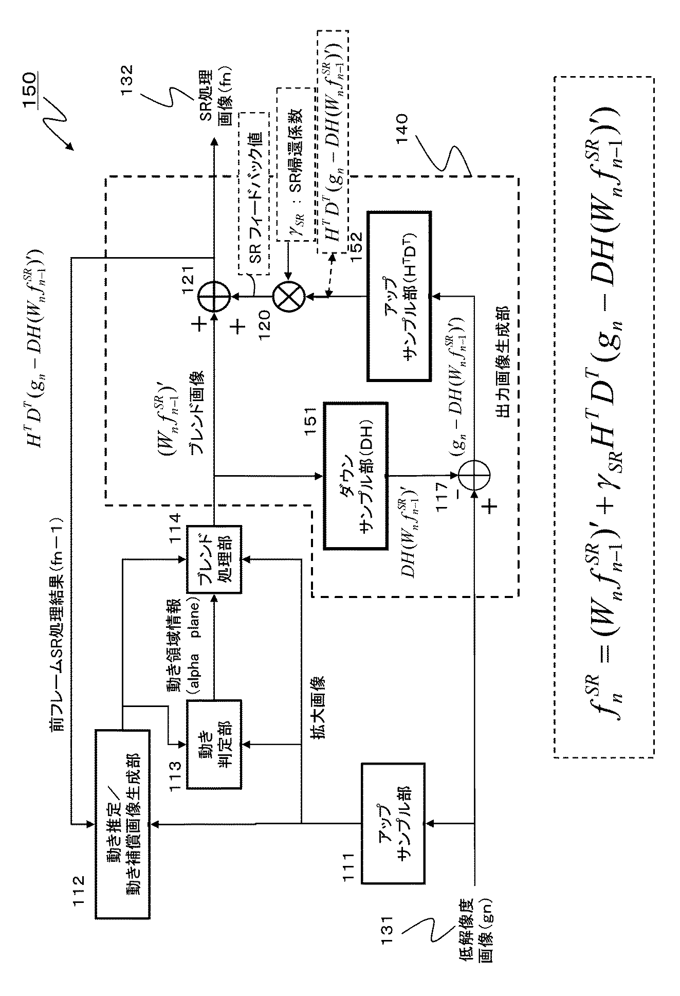
なお、上記式(式1)において、各パラメータは以下のパラメータである。
n:フレーム番号(n−1フレームとnフレームは例えば動画の連続フレーム)
gn:入力画像(nフレームの低解像度画像)
fn SR:フレームnの超解像処理結果画像(=高解像度画像)
fn−1 SR:フレームn−1の超解像処理結果画像(=高解像度画像)
Wn:フレームnのフレームn−1に対する動き情報(動きベクトルまたは行列など)
H:ボケ付加処理(ボケフィルタ行列)
D:ダウンサンプル処理(ダウンサンプル処理行列)
(Wnfn−1 SR)':ブレンド処理部の出力するブレンド画像
γSR:帰還係数
HT:Hの転置行列
DT:Dの転置行列
In the above formula (Formula 1), each parameter is the following parameter.
n: Frame number (n-1 frame and n frame are, for example, continuous frames of moving images)
gn: Input image (low resolution image of n frames)
f n SR : Super-resolution processing result image of frame n (= high resolution image)
f n−1 SR : Super-resolution processing result image of frame n−1 (= high resolution image)
Wn: motion information of frame n with respect to frame n−1 (motion vector or matrix, etc.)
H: Blur addition processing (blur filter matrix)
D: Downsample processing (downsample processing matrix)
(W n f n−1 SR ) ′: Blend image output from blend processing unit γ SR : Feedback coefficient H T : Transposed matrix of H D T : Transposed matrix of D
図1に示す超解像処理回路10を実現するハードウェアを構成する場合の問題点として回路規模の増大や処理効率の低下といつた問題がある。例えば、図1に示すアップサンプル部,ダウンサンプル部、ボケ付加部、逆ボケ付加部の処理にはフィルタ処理が適用されることになり、これら多くのフィルタリング処理を行うためには画素値の記憶のためのRAMが必要となる。フィルタリングのタップ数が大きくなると、必要となるメモリ容量も大きくなり、メモリアクセスを高速に行うためには、高性能のCPU等が必要となり、ハードウェアの大型化、コストの増大が懸念される。
Problems that arise when configuring the hardware for realizing the
本発明は、例えば上記問題点に鑑みてなされたものであり、回路規模の縮小や処理の効率化を実現した超解像処理を実現する画像処理装置、および画像処理方法、並びにプログラムを提供することを目的とする。 The present invention has been made in view of the above problems, for example, and provides an image processing apparatus, an image processing method, and a program that realize super-resolution processing that realizes reduction in circuit scale and efficiency in processing. For the purpose.
本発明の第1の側面は、
第1の解像度の入力画像を、前記第1の解像度より高い第2の解像度の画像の持つ画素数に合わせるアップサンプル処理を実行するアップサンプル部と、
前記アップサンプル画像と、前記第2の解像度を持つ参照画像との差分情報を利用して、前記参照画像を前記アップサンプル画像の被写体位置に合わせる補正処理により動き補償画像を生成する動き補償画像生成部と、
前記アップサンプル画像と前記動き補償画像を画像領域単位で比較し、領域単位の画素値一致度が高い領域ほど参照画像のブレンド比率を高く設定して、前記アップサンプル画像と前記参照画像とのブレンド処理を実行してブレンド画像を生成するブレンド処理部と、
前記ブレンド画像と前記入力画像の差分情報を生成し、前記ブレンド画像と前記差分情報との合成により第2の解像度を持つ高解像度画像を生成する出力画像生成部を有し、
前記出力画像生成部は、前記差分情報の生成処理に必要とするフィルタリング処理を2回以下とした構成を有する画像処理装置にある。
The first aspect of the present invention is:
An upsampling unit that executes an upsampling process for matching an input image having a first resolution to the number of pixels of an image having a second resolution higher than the first resolution;
Motion compensated image generation for generating a motion compensated image by correction processing that matches the reference image with the subject position of the upsampled image using difference information between the upsampled image and the reference image having the second resolution And
The upsampled image and the motion compensated image are compared for each image area, and the blend ratio of the upsampled image and the reference image is set by setting the blend ratio of the reference image higher in a region where the pixel value matching degree of the region unit is higher. A blend processing unit that executes processing to generate a blend image;
An output image generation unit that generates difference information between the blend image and the input image, and generates a high-resolution image having a second resolution by combining the blend image and the difference information;
The output image generation unit is in an image processing apparatus having a configuration in which a filtering process necessary for the generation process of the difference information is performed twice or less.
さらに、本発明の画像処理装置の一実施態様において、前記出力画像生成部は、前記ブレンド画像に対するボケ付加処理を実行するボケ付加部と、前記ボケ付加部の出力画像を前記第1の解像度の構成画素数まで低下させる画素間引き処理を実行するサブサンプル部と、前記入力画像と、前記サブサンプル部の出力画像との対応画素値の差分情報を出力する差分器と、差分器の出力する差分画像を前記第2の解像度の画素数に合わせるための0画素値のパディング処理を実行する0パディング処理部と、前記0パディング処理部の処理結果に対して、前記ボケ付加処理と逆の処理である逆ボケ付加処理を実行する逆ボケ付加部と、前記逆ボケ付加部の出力画像に対して予め設定した帰還係数を乗算する乗算器と、前記ブレンド画像と、前記乗算器の出力との対応画素値の加算処理を実行する加算器を有する。
Furthermore, in an embodiment of the image processing apparatus of the present invention, the output image generation unit includes a blur addition unit that performs a blur addition process on the blend image, and outputs an output image of the blur addition unit with the first resolution. A subsample unit that performs pixel thinning processing to reduce the number of constituent pixels, a differencer that outputs difference information of corresponding pixel values between the input image and an output image of the subsampler, and a difference output by the
さらに、本発明の画像処理装置の一実施態様において、前記出力画像生成部は、前記ブレンド画像を前記第1の解像度の構成画素数まで低下させるダウンサンプル処理を実行するダウンサンプル部と、前記入力画像と、前記ダウンサンプル部の出力画像との対応画素値の差分情報を出力する差分器と、差分器の出力する差分画像を前記第2の解像度の画素数に合わせるアップサンプル処理を実行するアップサンプル部と、前記アップサンプル部の出力画像に対して予め設定した帰還係数を乗算する乗算器と、前記ブレンド画像と、前記乗算器の出力との対応画素値の加算処理を実行する加算器を有する。 Furthermore, in an embodiment of the image processing apparatus of the present invention, the output image generation unit includes a downsampling unit that performs a downsampling process for reducing the blended image to the number of constituent pixels of the first resolution, and the input A differencer that outputs difference information of corresponding pixel values between an image and an output image of the downsampling unit, and an upsampling process that matches the difference image output by the differencer with the number of pixels of the second resolution A sample unit, a multiplier that multiplies an output image of the upsample unit by a preset feedback coefficient, and an adder that performs an addition process of corresponding pixel values of the blend image and the output of the multiplier Have.
さらに、本発明の画像処理装置の一実施態様において、前記出力画像生成部は、前記ブレンド画像を前記第1の解像度の構成画素数まで低下させるダウンサンプル処理と、前記第2の解像度の画素数に合わせるアップサンプル処理を実行する統合フィルタと、前記統合フィルタの出力に対して、予め設定した帰還係数を乗算する第1乗算器と、前記ブレンド画像と、前記乗算器の出力との対応画素値の差分を算出する差分器と、前記入力画像に対するアップサンプル処理を実行するアップサンプル部の出力に対して、予め設定した帰還係数を乗算する第2乗算器と、前記差分器の出力と前記第2乗算器の出力との加算処理を実行する加算器を有する。 Furthermore, in an embodiment of the image processing apparatus of the present invention, the output image generation unit includes a down-sampling process for reducing the blended image to the number of constituent pixels of the first resolution, and the number of pixels of the second resolution. Pixel values corresponding to an integrated filter that executes up-sampling processing to match, a first multiplier that multiplies an output of the integrated filter by a preset feedback coefficient, the blended image, and an output of the multiplier A second subtractor for multiplying the output of the upsampling unit for executing the upsampling process on the input image by a preset feedback coefficient, the output of the subtractor, and the first It has an adder for executing addition processing with the output of the two multipliers.
さらに、本発明の画像処理装置の一実施態様において、前記統合フィルタは、位相ごとに異なる値を畳み込むポリフェーズフィルタによって構成される。 Furthermore, in one embodiment of the image processing apparatus of the present invention, the integrated filter is configured by a polyphase filter that convolves a different value for each phase.
さらに、本発明の第2の側面は、
画像処理装置において解像度変換処理を実行する画像処理方法であり、
アップサンプル部が、第1の解像度の入力画像を、前記第1の解像度より高い第2の解像度の画像の持つ画素数に合わせるアップサンプル処理を実行するアップサンプル処理ステップと、
動き補償画像生成部が、前記アップサンプル画像と、前記第2の解像度を持つ参照画像との差分情報を利用して、前記参照画像を前記アップサンプル画像の被写体位置に合わせる補正処理により動き補償画像を生成する動き補償画像生成ステップと、
ブレンド処理部が、前記アップサンプル画像と前記動き補償画像を画像領域単位で比較し、領域単位の画素値一致度が高い領域ほど参照画像のブレンド比率を高く設定して、前記アップサンプル画像と前記参照画像とのブレンド処理を実行してブレンド画像を生成するブレンド処理ステップと、
出力画像生成部が、前記ブレンド画像と前記入力画像の差分情報を生成し、前記ブレンド画像と前記差分情報との合成により第2解像度を持つ高解像度画像を生成する出力画像生成ステップを有し、
前記出力画像生成ステップは、前記差分情報の生成処理に必要とするフィルタリング処理を2回以下とした処理により高解像度画像を生成するステップである画像処理方法にある。
Furthermore, the second aspect of the present invention provides
An image processing method for executing resolution conversion processing in an image processing apparatus,
An up-sampling step in which the up-sampling unit executes an up-sampling process for matching an input image having a first resolution with the number of pixels of an image having a second resolution higher than the first resolution;
A motion compensated image is generated by a correction process in which the motion compensated image generating unit uses the difference information between the upsampled image and the reference image having the second resolution to match the reference image with the subject position of the upsampled image. A motion compensated image generating step for generating
The blend processing unit compares the upsampled image and the motion compensated image in units of image regions, and sets a higher blend ratio of a reference image in a region where the pixel value matching degree in units of regions is higher. A blending step for generating a blended image by executing a blending process with a reference image;
An output image generating unit that generates difference information between the blend image and the input image and generates a high-resolution image having a second resolution by combining the blend image and the difference information;
The output image generation step is an image processing method which is a step of generating a high-resolution image by performing a filtering process required for the difference information generation process twice or less.
さらに、本発明の第3の側面は、
画像処理装置において解像度変換処理を実行させるプログラムであり、
アップサンプル部に、第1の解像度の入力画像を、前記第1の解像度より高い第2の解像度の画像の持つ画素数に合わせるアップサンプル処理を実行させるアップサンプル処理ステップと、
動き補償画像生成部に、前記アップサンプル画像と、前記第2の解像度を持つ参照画像との差分情報を利用して、前記参照画像を前記アップサンプル画像の被写体位置に合わせる補正処理により動き補償画像を生成させる動き補償画像生成ステップと、
ブレンド処理部に、前記アップサンプル画像と前記動き補償画像を画像領域単位で比較させ、領域単位の画素値一致度が高い領域ほど参照画像のブレンド比率を高く設定して前記アップサンプル画像と前記参照画像とのブレンド処理を実行してブレンド画像を生成させるブレンド処理ステップと、
出力画像生成部に、前記ブレンド画像と前記入力画像の差分情報を生成させ、前記ブレンド画像と前記差分情報との合成により第2解像度を持つ高解像度画像を生成させる出力画像生成ステップを実行させ、
前記出力画像生成ステップは、前記差分情報の生成処理に必要とするフィルタリング処理を2回以下とした処理により高解像度画像を生成させるステップであるプログラムにある。
Furthermore, the third aspect of the present invention provides
A program for executing resolution conversion processing in an image processing apparatus;
An up-sampling step for causing the up-sampling unit to perform an up-sampling process for matching an input image having a first resolution with the number of pixels of an image having a second resolution higher than the first resolution;
A motion compensated image is generated by a correction process for adjusting the reference image to the subject position of the upsampled image using the difference information between the upsampled image and the reference image having the second resolution in the motion compensated image generating unit. A motion compensated image generating step for generating
The blend processing unit compares the upsampled image and the motion compensated image in units of image regions, and sets the blend ratio of the reference image higher in a region where the pixel value matching degree in the region unit is higher, and the upsampled image and the reference A blending step for generating a blended image by executing a blending process with the image;
Causing the output image generation unit to generate difference information between the blend image and the input image, and to execute an output image generation step of generating a high-resolution image having a second resolution by combining the blend image and the difference information;
The output image generation step is a program that is a step of generating a high-resolution image by a process in which the filtering process required for the difference information generation process is performed twice or less.
なお、本発明のプログラムは、例えば、様々なプログラム・コードを実行可能な情報処理装置やコンピュータ・システムに対して、コンピュータ可読な形式で提供する記憶媒体、通信媒体によって提供可能なプログラムである。このようなプログラムをコンピュータ可読な形式で提供することにより、情報処理装置やコンピュータ・システム上でプログラムに応じた処理が実現される。 The program of the present invention is, for example, a program that can be provided by a storage medium or a communication medium provided in a computer-readable format to an information processing apparatus or a computer system that can execute various program codes. By providing such a program in a computer-readable format, processing corresponding to the program is realized on the information processing apparatus or the computer system.
本発明のさらに他の目的、特徴や利点は、後述する本発明の実施例や添付する図面に基づくより詳細な説明によって明らかになるであろう。なお、本明細書においてシステムとは、複数の装置の論理的集合構成であり、各構成の装置が同一筐体内にあるものには限らない。 Other objects, features, and advantages of the present invention will become apparent from a more detailed description based on embodiments of the present invention described later and the accompanying drawings. In this specification, the system is a logical set configuration of a plurality of devices, and is not limited to one in which the devices of each configuration are in the same casing.
本発明の一実施例の構成によれば、フィルタリング処理を簡略化した超解像処理を実現する装置および方法が提供される。例えば、以下の処理により高解像度画像を生成する。低解像度の入力画像を高解像度画像の持つ画素数に合わせたアップサンプル画像を生成し、高解像度の参照画像をアップサンプル画像の被写体位置に合わせた動き補償画像を生成する。さらに。アップサンプル画像と動き補償画像を画像領域単位で比較し、領域単位の画素値一致度が高い領域ほど参照画像のブレンド比率を高く設定してアップサンプル画像と参照画像をブレンドしたブレンド画像を生成する。さらに、ブレンド画像と入力画像の差分を生成し、ブレンド画像と差分情報との合成処理により高解像度画像を生成する。本発明の構成では、差分情報の生成処理に必要とするフィルタリング処理を2回以下として、装置の小型化や処理の効率化を実現した。 According to the configuration of one embodiment of the present invention, an apparatus and method for realizing super-resolution processing with simplified filtering processing are provided. For example, a high resolution image is generated by the following processing. An up-sampled image is generated by matching the low-resolution input image with the number of pixels of the high-resolution image, and a motion-compensated image is generated by matching the high-resolution reference image with the subject position of the up-sampled image. further. Compare the upsampled image with the motion compensated image in units of image areas, and generate a blended image that blends the upsampled image with the reference image by setting the blend ratio of the reference image higher in the region where the pixel value matching degree of the region unit is higher. . Further, a difference between the blend image and the input image is generated, and a high-resolution image is generated by combining the blend image and the difference information. In the configuration of the present invention, the filtering process required for the difference information generation process is reduced to twice or less, thereby realizing downsizing of the apparatus and efficiency of the process.
以下、図面を参照しながら本発明の画像処理装置、および画像処理方法、並びにプログラムの詳細について説明する。なお、説明は以下の項目に従って行う。
1.フィルタ処理部を統合した構成によって超解像処理を行う画像処理装置について
1−1.実施例1
1−2.実施例2
1−3.実施例3
2.画像処理装置のハードウェア構成例について
The details of the image processing apparatus, image processing method, and program of the present invention will be described below with reference to the drawings. The description will be made according to the following items.
1. 1. Image processing apparatus that performs super-resolution processing with a configuration in which filter processing units are integrated 1-1. Example 1
1-2. Example 2
1-3. Example 3
2. Example of hardware configuration of image processing device
[1.フィルタ処理部を統合した構成によって超解像処理を行う画像処理装置について]
フィルタ処理部を統合した構成によって超解像処理を行う画像処理装置について説明する。
[1. Regarding an image processing apparatus that performs super-resolution processing by integrating a filter processing unit]
An image processing apparatus that performs super-resolution processing with a configuration in which filter processing units are integrated will be described.
先に図1を参照して説明したように、超解像処理を実行する回路には、アップサンプル部,ダウンサンプル部、ボケ付加部、逆ボケ付加部などの処理部が含まれる。これらの処理にはフィルタ処理が適用される。これら多くのフィルタリング処理を行うためには画素値の記憶のためのRAMが必要となり、フィルタリングのタップ数が大きくなると必要となるメモリ容量も大きくなる。またメモリアクセスを高速に行うためには高性能のCPU等が必要となり、ハードウェアの大型化、コストの増大が懸念される。
以下において説明する画像処理装置は、超解像処理におけるフィルタリング処理の簡略化を実現するものである。
As described above with reference to FIG. 1, a circuit that performs super-resolution processing includes processing units such as an up-sampling unit, a down-sampling unit, a blur adding unit, and a reverse blur adding unit. A filter process is applied to these processes. In order to perform these many filtering processes, a RAM for storing pixel values is required, and the required memory capacity increases as the number of taps for filtering increases. In addition, a high-performance CPU or the like is required to perform memory access at high speed, and there is a concern about an increase in hardware size and cost.
An image processing apparatus described below realizes simplification of filtering processing in super-resolution processing.
(1−1.実施例1)
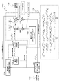
図2を参照して本発明の第1実施例に係る画像処理装置100の構成例について説明する。
図2に示す画像処理装置100は、先に図1を参照して説明した回路と同様、低解像度画像gn131を入力して、超解像処理を実行して高解像度画像fn(=SR処理画像132)を出力する。
(1-1. Example 1)
A configuration example of the
Similar to the circuit described above with reference to FIG. 1, the
図1を参照して説明した構成との差異は、図2に示す出力画像生成部130の構成である。具体的には以下のような変更がなされている。
図1におけるダウンサンプル部16を、図2の構成では、単なる画素の間引き処理を実行するサブサンプル部116に変更したこと、
図1におけるアップサンプル部18を図2の構成では、画素数増加に伴う増加画素部分に画素値0を追加する0パディング処理部に変更したこと、
これらの構成変更である。
その他の構成は、図1に示す構成と同様の構成である。
The difference from the configuration described with reference to FIG. 1 is the configuration of the output
The down-
In the configuration of FIG. 2, the
These are configuration changes.
Other configurations are the same as those shown in FIG.
画像処理装置100には、解像度を高める処理の対象となる低解像度画像gnがアップサンプル部111に入力され、画素数の変換(画像拡大処理)が実行される。具体的には、アップサンプル部111では、入力画像の画素数を出力予定の画像の画素数に合わせる画像拡大処理、例えば1画素を複数画素に分割設定する処理を行う。すなわち、第1の解像度(低解像度)の入力画像を、第1の解像度(低解像度)より高い第2の解像度(高解像度)の画像の持つ画素数に合わせるアップサンプル処理を実行する。
The
動き推定/動き補償画像生成部112は、前フレームの処理において生成され、参照画像として利用する高解像度画像fn−1、アップサンプリングした低解像度画像gn間の動きの大きさを検出する。具体的には動きベクトルを計算する。さらに、検出した動きベクトルを利用して、参照画像として利用する高解像度画像fn−1に対する動き補償処理を行う。これにより高解像度画像fn−1に動き補償処理が施され、アップサンプリングした低解像度画像gnと被写体の位置が同じに設定された動き補償画像が生成される。
Motion estimation / motion compensation
動き判定部113では、動き補正(MC)処理により生成された動き補償高解像度画像、及びアップサンプルした低解像度画像を比較して、動き補正(MC)がうまく適用できていない領域を検出する。例えば被写体自身が動いている場合、動き補償失敗領域が発生する。
The
参照画像としての高解像度画像fn−1の動き補償画像と、アップサンプリングした低解像度画像gnと被写体の位置が同じに設定された領域を動き補償成功領域とし、同じ位置に設定されなかった領域を動き領域失敗領域として区別した動き領域情報(αマップ[0:1])を生成して出力する。 The high resolution image f n-1 of the motion compensation image as a reference image, a region of which position has been set the same low-resolution image g n and subject upsampled and motion compensation successful region was not set to the same position The motion area information (α map [0: 1]) that distinguishes the area as the motion area failure area is generated and output.
ブレンド処理部114は、動き推定/動き補償画像生成部12の生成した高解像度画像fn−1に対する動き補償結果画像、
アップサンプリング部11で低解像度画像gnに対してアップサンプリングされたアップサンプル画像、
動き領域情報(αマップ[0:1])、
これらを入力する。
The
Upsampled upsampled
Movement area information (α map [0: 1]),
Enter these.
ブレンド処理部114は、これらの入力情報を利用して、以下の式に基づいてブレンド結果としてのブレンド画像を出力する。
ブレンド画像=(1−α)(アップサンプル画像)+α(動き補償結果画像)
ブレンド処理部114は、アップサンプル画像と動き補償画像を画像領域単位で比較し、領域単位の画素値一致度が高い領域ほど参照画像のブレンド比率を高く設定して、アップサンプル画像と参照画像とのブレンド処理を実行してブレンド画像を生成する。
The
Blend image = (1-α) (upsampled image) + α (motion compensation result image)
The
出力画像生成部130は、ブレンド画像と入力画像の差分情報を生成し、ブレンド画像と差分情報との合成により第2の解像度を持つ高解像度画像を生成する。
出力画像生成部130内の処理について説明する。
The output
Processing in the output
ボケ付加部115は、ブレンド処理部14の生成したブレンド画像を入力してブレンド画像に対するボケ付加処理を実行する。具体的には、空間解像度の劣化のシミュレーションにより、ブレンド画像に対するボケ付加処理を行う。例えば、あらかじめ測定しておいた点広がり関数(Point Spread Function)をフィルタとして画像へ畳み込みを行う。
The
サブサンプル部116では、高解像度画像を入力画像と同じ解像度までダウンサンプリングする処理を実行する。本実施例の構成のサブサンプル部116では、画素の単なる間引き処理を実行する。具体的には、ボケ付加部115の出力するブレンド画像を、入力画像と同じ第1の解像度(低解像度)の構成画素数まで低下させる画素間引き処理を実行する。
The
その後、差分器117では、サブサンプル部116、低解像度画像gnの画素毎の差分値を計算する。差分器117は、入力画像と、サブサンプル部の出力画像との対応画素値の差分情報を出力する。
0パディング処理部118は、差分器117の出力する差分画像を第2の解像度(高解像度)の画像の画素数に合わせるための0画素値のパディング処理を実行する。すなわち、生成予定の高解像度画像に相当する画素数に変換する処理として、増加する画素位置に画素値0を設定する0パディング処理を行なう。
Thereafter, the
The 0
さらに、逆ボケ付加部119で、ボケの付加処理と逆の処理を行う。動作としては、ボケ付加部115で用いた点広がり関数(PSF:Point Spread Function)との相関の計算に相当する処理を行う。
Further, the reverse
逆ボケ付加部119の出力は、乗算器120において予め設定した帰還係数γと乗算後、加算器121に出力され、プレンド処理部114の出力するブレンド画像と加算され、出力される。
この加算器121の出力が入力画像gnを高解像度化した画像(SR処理画像)となる。
The output of the inverse
The output of the
この図2に示す構成において実行する処理を式で示すと以下のように表現することが可能である。 The processing executed in the configuration shown in FIG. 2 can be expressed as follows using an equation.
なお、上記式(式2)において、各パラメータは以下のパラメータである。
n:フレーム番号(n−1フレームとnフレームは例えば動画の連続フレーム)
gn:入力画像(nフレームの低解像度画像)
fn SR:フレームnの超解像処理結果画像(=高解像度画像)
fn−1 SR:フレームn−1の超解像処理結果画像(=高解像度画像)
Wn:フレームnのフレームn−1に対する動き情報(動きベクトルまたは行列など)
H:ボケ付加処理(ボケフィルタ行列)
D:ダウンサンプル処理(ダウンサンプル処理行列)
(Wnfn−1 SR)':ブレンド処理部の出力するブレンド画像
γSR:帰還係数
HT:Hの転置行列
DT:Dの転置行列
In the above formula (Formula 2), each parameter is the following parameter.
n: Frame number (n-1 frame and n frame are, for example, continuous frames of moving images)
gn: Input image (low resolution image of n frames)
f n SR : Super-resolution processing result image of frame n (= high resolution image)
f n−1 SR : Super-resolution processing result image of frame n−1 (= high resolution image)
Wn: motion information of frame n with respect to frame n−1 (motion vector or matrix, etc.)
H: Blur addition processing (blur filter matrix)
D: Downsample processing (downsample processing matrix)
(W n f n−1 SR ) ′: Blend image output from blend processing unit γ SR : Feedback coefficient H T : Transposed matrix of H D T : Transposed matrix of D
上記式は、図1を参照して説明した式と同様の式である。
サブサンプル部116の実行する間引き処理が[D=ダウンサンプル処理]に対応し、0パディング処理部118の実行する処理が[DT=アップサンプル処理]に対応することになる。
The above equation is the same as the equation described with reference to FIG.
The decimation process executed by the
この図2に示す画像処理装置100では、
図1におけるダウンサンプル部16を、単なる画素の間引き処理を実行するサブサンプル部116に変更し、図1におけるアップサンプル部18を、画素数増加に伴う増加画素部分に画素値0を追加する0パディング処理部に変更している。
この処理により、これらの処理部では、フィルタリング処理が不要となり、画素値の記憶のためのメモリやメモリアクセス処理が不要となり、装置の小型化、処理の効率化が実現される。
In the
The
With this process, these processing units do not require a filtering process, a memory for storing pixel values and a memory access process are not required, and the apparatus can be downsized and the process efficiency can be improved.
すなわち、出力画像生成部130内で実行するブレンド画像と入力画像(低解像度画像gn131)との差分情報の生成処理では、ボケ付加部115、逆ボケ付加部119においてのみフィルタリング処理が実行され、出力画像生成部130内で実行するフィルタリング処理は2回のみとなる。このように、本実施例の構成では、フィルタリング処理が削減され、画素値の記憶のためのメモリやメモリアクセス処理が不要となり、装置の小型化、処理の効率化が実現される。
That is, in the difference information generation process between the blend image and the input image (low-resolution image gn131) executed in the output
(1−2.実施例2)
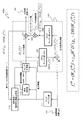
次に、図3を参照して、本発明の第2実施例に係る画像処理装置150の構成例について説明する。
図3に示す画像処理装置150は、図1、図2を参照して説明した回路と同様、低解像度画像gn131を入力して、超解像処理を実行して高解像度画像fn(=SR処理画像132)を出力する。
図3に示す画像処理装置150は、図2に示す構成をさらに簡略化した構成を有する。
(1-2. Example 2)
Next, a configuration example of the
Similar to the circuit described with reference to FIGS. 1 and 2, the
An
図2に示す画像処理装置100との差異を中心として説明する。
図3に示す画像処理装置150は、図3に示す出力画像生成部140の構成が図2に示す構成と異なっている。具体的には以下のような変更がなされている。
図2に示すボケ処理部115と、サブサンプル部116を統合して図3に示すダウンサンプル部151としている。
図2に示す0パディング処理部118と、逆ボケ処理部119を統合して図3に示すアップサンプル部152としている。
The description will focus on differences from the
The
The
The 0
その他の処理部は、図2に示す構成と同様である。
図3に示すダウンサンプル部151は、図2に示すボケ処理部115と、サブサンプル部116の実行する2つの処理を1回のフィルタリング処理として実行する。
ダウンサンプル部151は、ブレンド処理部114の出力間するブレンド画像を第1の解像度(低解像度)の画像の構成画素数まで低下させるダウンサンプル処理を実行する。
Other processing units are the same as those shown in FIG.
The
The down-
同様に、図3に示すアップサンプル部152は、図2に示す0パディング処理部118と、逆ボケ処理部119の実行する2つの処理を1回のフィルタリング処理として実行する。アップサンプル部152は、差分器117の出力する差分画像を第2の解像度(高解像度)の画像の画素数に合わせるアップサンプル処理を実行する
Similarly, the
図3の構成において実行する処理を式で示すと以下のように表現することが可能である。 The processing executed in the configuration of FIG. 3 can be expressed as follows:
この式(式3)は、図1、図2の構成において実行する処理を示す式と同様の式である。
図3の構成において、ダウンサンプル部151は、上述したように、図2に示すボケ処理部115と、サブサンプル部116の実行する2つの処理を1回のフィルタリング処理として実行し、ダウンサンプル部151の出力は、図3中に示すように以下のように示される。
DH(Wnfn−1 SR)'
This expression (Expression 3) is the same expression as the expression indicating the processing executed in the configuration of FIGS.
In the configuration of FIG. 3, as described above, the down-
DH (W n f n-1 SR) '
また、差分器117の出力は、図3中に示すように以下のように示される。
gn−DH(Wnfn−1 SR)'
さらに、アップサンプル部152の出力は、図3中に示すように以下のように示される。
HTDT(gn−DH(Wnfn−1 SR)')
Further, the output of the
g n -DH (W n f n -1 SR) '
Further, the output of the
H T D T (g n -DH (W n f n-1 SR) ')
なお、各パラメータは、実施例1において説明したと同様のパラメータである。 Each parameter is the same parameter as described in the first embodiment.
このように、図3に示す画像処理装置150では、ダウンサンプル部151において、図2に示すボケ処理部115と、サブサンプル部116の実行する2つの処理を1回のフィルタリング処理として実行し、アップサンプル部152において、図2に示す0パディング処理部118と、逆ボケ処理部119の実行する2つの処理を1回のフィルタリング処理として実行する。
As described above, in the
図2に示す構成に比較して、構成が簡略化し、またフィルタリング処理数も減少する。結果としてハードウェア構成の小型化、コストダウン、さらに処理の効率化むが実現される。 Compared to the configuration shown in FIG. 2, the configuration is simplified and the number of filtering processes is reduced. As a result, it is possible to reduce the hardware configuration, reduce the cost, and increase the processing efficiency.
(1−3.実施例3)
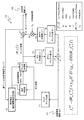
次に、図4を参照して、本発明の第3実施例に係る画像処理装置180の構成例について説明する。
図4に示す画像処理装置180は、図1〜図3を参照して説明した回路と同様、低解像度画像gn131を入力して、超解像処理を実行して高解像度画像fn(=SR処理画像132)を出力する。
図4に示す画像処理装置180は、図3に示す構成をさらに簡略化した構成を有する。
(1-3. Example 3)
Next, a configuration example of the
Similar to the circuit described with reference to FIGS. 1 to 3, the
An
図3に示す画像処理装置150との差異を中心として説明する。
図4に示す画像処理装置180は、図4に示す出力画像生成部170の構成が図3に示す構成と異なっている。具体的には以下のような変更がなされている。
図3に示す2つのアップサンプル部、すなわちアップサンプル部111と、アップサンプル部152をまとめて、図4に示す構成では、1つのアップサンプル部181としている。
さらに、図3に示すダウンサンプル部151と差分器117を、図4の構成では、統合フィルタ(ポリフェーズフィルタ)182に置き換えている。
The description will focus on differences from the
4 is different from the configuration shown in FIG. 3 in the configuration of the output
The two upsampling units shown in FIG. 3, that is, the
Further, the
統合フィルタ(ポリフェーズフィルタ)182は、ブレンド処理部114の生成するブレンド画像を第1の解像度(低解像度)の画像の構成画素数まで低下させるダウンサンプル処理と、第2の解像度(高解像度)の画像の画素数に合わせるアップサンプル処理を実行する。統合フィルタ(ポリフェーズフィルタ)182は、例えばポリフェーズフィルタであり、位相毎に異なる値を畳み込むフィルタリング処理を行う。
The integrated filter (polyphase filter) 182 down-samples the blend image generated by the
なお、この出力画像生成部170の構成変更に伴い、統合フィルタ(ポリフェーズフィルタ)182の出力に対するSR帰還係数との乗算処理を実行する乗算器183、ブレンド処理部の出力するブレンド画像から乗算器183の出力を減算させる差分器184を設けている。
差分器184の出力が、加算器121に出力されてSRフィードバック値と加算される。
Along with the configuration change of the output
The output of the
図4に示す画像処理装置180の実行する処理を式で示すと以下のように表現することが可能である。
The processing executed by the
この式(式4)の第1行は、図1〜図3の構成において実行する処理を示す式と同じ式である。第2行、第3行は、式の変形を行った結果であり、第3行の式が図4に示す構成と対応している。 The first row of this formula (formula 4) is the same formula as the formula showing the processing executed in the configuration of FIGS. The second row and the third row are the results of the transformation of the formula, and the formula in the third row corresponds to the configuration shown in FIG.
すなわち、アップサンプル部181では、逆ボケ付加処理(HT)とアップサンプル処理(DT)に相当する処理を実行し、アップサンプル部181の出力は、図4中に示すように、以下の式で示すことができる。
HTDTgn、
That is, the
H T D T g n,
また、統合フィルタ(ポリフェーズフィルタ)182は、ブレンド画像を入力画像に相当する第1の解像度(低解像度)の構成画素数まで低下させるダウンサンプル処理と、第2の解像度(高解像度)の画素数に合わせるアップサンプル処理を実行する。例えば位相毎に異なる値を畳み込むフィルタリング処理を行うポリフェーズフィルタによって構成される。 Further, the integrated filter (polyphase filter) 182 performs down-sampling processing for reducing the blend image to the number of constituent pixels of the first resolution (low resolution) corresponding to the input image, and pixels of the second resolution (high resolution). Execute upsampling processing according to the number. For example, it comprises a polyphase filter that performs a filtering process that convolves a different value for each phase.
このフィルタリング処理は、
HTDTDH、
として示すことができ、統合フィルタ(ポリフェーズフィルタ)182の出力は、
(HTDTDH)(Wnfn−1 SR)'
となる。
This filtering process
H T D T DH,
And the output of the integrated filter (polyphase filter) 182 is
(H T D T DH) ( W n f n-1 SR) '
It becomes.
また、図4中の差分器184の出力は、図4の(A)に示すように、上記式(式4)の前半部分に対応し、
(1−γSRHTDTDH)(Wnfn−1 SR)'
上記のように示すことができる。
また、乗算器120の出力は、図4の(B)に示すように、上記式(式4)の後半部分に対応し、
γSRHTDTgn、
上記のように示すことができる。
Also, the output of the
(1-γ SR H T D T DH) (W n f n-1 SR) '
It can be shown as above.
The output of the
γ SR H T D T g n ,
It can be shown as above.
結果として、加算器121の出力は、上記式(式4)によって示される値、すなわち、
fn SR=(1−γSRHTDTDH)(Wnfn−1 SR)'+γSRHTDTgn、
となる。
この式は、前記した式4の展開から理解されるように、図1〜図3の構成における処理と等化であり、図4に示す構成を用いることで、超解像処理結果fn SRが出力されることになる。
As a result, the output of the
f n SR = (1-γ SR H T D T DH) (W n f n-1 SR) '+ γ SR H T D T g n,
It becomes.
As can be understood from the development of
この図4に示す画像処理装置180では、フィルタリング処理は、アップサンプル部181と、統合フィルタ(ポリフェーズフィルタ)182であり、図1に示す構成と比較して、フィルタ処理の必要となる構成が現象し、結果としてハードウェア構成の小型化、コストダウン、さらに処理の効率化が実現されることになる。
In the
[2.画像処理装置のハードウェア構成例について]
最後に、図5を参照して、上述した処理を実行する画像処理装置の1つのハードウェア構成例について説明する。CPU(Central Processing Unit)901は、ROM(Read Only Memory)902、または記憶部908に記憶されているプログラムに従って各種の処理を実行する。例えば、上述の各実施例において説明した超解像処理等の画像処理を実行する。RAM(Random Access Memory)903には、CPU901が実行するプログラムやデータなどが適宜記憶される。これらのCPU901、ROM902、およびRAM903は、バス904により相互に接続されている。
[2. Example of hardware configuration of image processing apparatus]
Finally, with reference to FIG. 5, an example of a hardware configuration of an image processing apparatus that performs the above-described processing will be described. A CPU (Central Processing Unit) 901 executes various processes according to a program stored in a ROM (Read Only Memory) 902 or a
CPU901はバス904を介して入出力インタフェース905に接続され、入出力インタフェース905には、キーボード、マウス、マイクロホンなどよりなる入力部906、ディスプレイ、スピーカなどよりなる出力部907が接続されている。CPU901は、入力部906から入力される指令に対応して各種の処理を実行し、処理結果を例えば出力部907に出力する。
The
入出力インタフェース905に接続されている記憶部908は、例えばハードディスクからなり、CPU901が実行するプログラムや各種のデータを記憶する。通信部909は、インターネットやローカルエリアネットワークなどのネットワークを介して外部の装置と通信する。
A
入出力インタフェース905に接続されているドライブ910は、磁気ディスク、光ディスク、光磁気ディスク、或いは半導体メモリなどのリムーバブルメディア911を駆動し、記録されているプログラムやデータなどを取得する。取得されたプログラムやデータは、必要に応じて記憶部908に転送され記憶される。
A
以上、特定の実施例を参照しながら、本発明について詳解してきた。しかしながら、本発明の要旨を逸脱しない範囲で当業者が実施例の修正や代用を成し得ることは自明である。すなわち、例示という形態で本発明を開示してきたのであり、限定的に解釈されるべきではない。本発明の要旨を判断するためには、特許請求の範囲の欄を参酌すべきである。 The present invention has been described in detail above with reference to specific embodiments. However, it is obvious that those skilled in the art can make modifications and substitutions of the embodiments without departing from the gist of the present invention. In other words, the present invention has been disclosed in the form of exemplification, and should not be interpreted in a limited manner. In order to determine the gist of the present invention, the claims should be taken into consideration.
また、明細書中において説明した一連の処理はハードウェア、またはソフトウェア、あるいは両者の複合構成によって実行することが可能である。ソフトウェアによる処理を実行する場合は、処理シーケンスを記録したプログラムを、専用のハードウェアに組み込まれたコンピュータ内のメモリにインストールして実行させるか、あるいは、各種処理が実行可能な汎用コンピュータにプログラムをインストールして実行させることが可能である。例えば、プログラムは記録媒体に予め記録しておくことができる。記録媒体からコンピュータにインストールする他、LAN(Local Area Network)、インターネットといったネットワークを介してプログラムを受信し、内蔵するハードディスク等の記録媒体にインストールすることができる。 The series of processing described in the specification can be executed by hardware, software, or a combined configuration of both. When executing processing by software, the program recording the processing sequence is installed in a memory in a computer incorporated in dedicated hardware and executed, or the program is executed on a general-purpose computer capable of executing various processing. It can be installed and run. For example, the program can be recorded in advance on a recording medium. In addition to being installed on a computer from a recording medium, the program can be received via a network such as a LAN (Local Area Network) or the Internet and can be installed on a recording medium such as a built-in hard disk.
なお、明細書に記載された各種の処理は、記載に従って時系列に実行されるのみならず、処理を実行する装置の処理能力あるいは必要に応じて並列的にあるいは個別に実行されてもよい。また、本明細書においてシステムとは、複数の装置の論理的集合構成であり、各構成の装置が同一筐体内にあるものには限らない。 Note that the various processes described in the specification are not only executed in time series according to the description, but may be executed in parallel or individually according to the processing capability of the apparatus that executes the processes or as necessary. Further, in this specification, the system is a logical set configuration of a plurality of devices, and the devices of each configuration are not limited to being in the same casing.
以上、説明したように、本発明の一実施例の構成によれば、フィルタリング処理を簡略化した超解像処理を実現する装置および方法が提供される。例えば、以下の処理により高解像度画像を生成する。低解像度の入力画像を高解像度画像の持つ画素数に合わせたアップサンプル画像を生成し、高解像度の参照画像をアップサンプル画像の被写体位置に合わせた動き補償画像を生成する。さらに。アップサンプル画像と動き補償画像を画像領域単位で比較し、領域単位の画素値一致度が高い領域ほど参照画像のブレンド比率を高く設定してアップサンプル画像と参照画像をブレンドしたブレンド画像を生成する。さらに、ブレンド画像と入力画像の差分を生成し、ブレンド画像と差分情報との合成処理により高解像度画像を生成する。本発明の構成では、差分情報の生成処理に必要とするフィルタリング処理を2回以下として、装置の小型化や処理の効率化を実現した。 As described above, according to the configuration of one embodiment of the present invention, an apparatus and a method for realizing super-resolution processing with simplified filtering processing are provided. For example, a high resolution image is generated by the following processing. An up-sampled image is generated by matching the low-resolution input image with the number of pixels of the high-resolution image, and a motion-compensated image is generated by matching the high-resolution reference image with the subject position of the up-sampled image. further. Compare the upsampled image with the motion compensated image in units of image areas, and generate a blended image that blends the upsampled image with the reference image by setting the blend ratio of the reference image higher in the region where the pixel value matching degree of the region unit is higher. . Further, a difference between the blend image and the input image is generated, and a high-resolution image is generated by combining the blend image and the difference information. In the configuration of the present invention, the filtering process required for the difference information generation process is reduced to twice or less, thereby realizing downsizing of the apparatus and efficiency of the process.
10 超解像処理装置
11 アップサンプル部
12 動き推定/動き補償画像生成部
13 動き判定部
14 ブレンド処理部
15 ボケ付加部
16 ダウンサンプル部
17 加算器
18 アップサンプル部
19 逆ボケ付加部
20 乗算器
21 差分器
31 低解像度画像
32 SR処理画像
110 画像処理装置
111 アップサンプル部
112 動き推定/動き補償画像生成部
113 動き判定部
114 ブレンド処理部
115 ボケ付加部
116 サブサンプル部
117 加算器
118 0パディング処理部
119 逆ボケ付加部
120 乗算器
121 差分器
131 低解像度画像
132 SR処理画像
150 画像処理装置
151 ダウンサンプル部
152 アップサンプル部
180 画像処理装置
181 アップサンプル部
182 統合フィルタ(ポリフェーズフィルタ)
182 乗算器
183 差分器
901 CPU
902 ROM
903 RAM
904 バス
905 入出力インタフェース
906 入力部
907 出力部
908 記憶部
909 通信部
910 ドライブ
911 リムーバブルメディア
DESCRIPTION OF
182
902 ROM
903 RAM
904 Bus 905 I /
Claims (7)
前記アップサンプル画像と、前記第2の解像度を持つ参照画像との差分情報を利用して、前記参照画像を前記アップサンプル画像の被写体位置に合わせる補正処理により動き補償画像を生成する動き補償画像生成部と、
前記アップサンプル画像と前記動き補償画像を画像領域単位で比較し、領域単位の画素値一致度が高い領域ほど参照画像のブレンド比率を高く設定して、前記アップサンプル画像と前記参照画像とのブレンド処理を実行してブレンド画像を生成するブレンド処理部と、
前記ブレンド画像と前記入力画像の差分情報を生成し、前記ブレンド画像と前記差分情報との合成により第2の解像度を持つ高解像度画像を生成する出力画像生成部を有し、
前記出力画像生成部は、前記差分情報の生成処理に必要とするフィルタリング処理を2回以下とした構成を有する画像処理装置。 An upsampling unit that executes an upsampling process for matching an input image having a first resolution to the number of pixels of an image having a second resolution higher than the first resolution;
Motion compensated image generation for generating a motion compensated image by correction processing that matches the reference image with the subject position of the upsampled image using difference information between the upsampled image and the reference image having the second resolution And
The upsampled image and the motion compensated image are compared for each image area, and the blend ratio of the upsampled image and the reference image is set by setting the blend ratio of the reference image higher in a region where the pixel value matching degree of the region unit is higher. A blend processing unit that executes processing to generate a blend image;
An output image generation unit that generates difference information between the blend image and the input image, and generates a high-resolution image having a second resolution by combining the blend image and the difference information;
The output image generation unit is an image processing apparatus having a configuration in which a filtering process necessary for the generation process of the difference information is performed twice or less.
前記ブレンド画像に対するボケ付加処理を実行するボケ付加部と、
前記ボケ付加部の出力画像を前記第1の解像度の構成画素数まで低下させる画素間引き処理を実行するサブサンプル部と、
前記入力画像と、前記サブサンプル部の出力画像との対応画素値の差分情報を出力する差分器と、
差分器の出力する差分画像を前記第2の解像度の画素数に合わせるための0画素値のパディング処理を実行する0パディング処理部と、
前記0パディング処理部の処理結果に対して、前記ボケ付加処理と逆の処理である逆ボケ付加処理を実行する逆ボケ付加部と、
前記逆ボケ付加部の出力画像に対して予め設定した帰還係数を乗算する乗算器と、
前記ブレンド画像と、前記乗算器の出力との対応画素値の加算処理を実行する加算器を有する請求項1に記載の画像処理装置。 The output image generation unit
A blur addition unit that performs blur addition processing on the blend image;
A sub-sample unit that performs a pixel thinning process for reducing the output image of the blur adding unit to the number of constituent pixels of the first resolution;
A differentiator that outputs difference information of corresponding pixel values between the input image and the output image of the subsample unit;
A 0 padding processing unit that performs padding processing of 0 pixel values for matching the difference image output from the differentiator with the number of pixels of the second resolution;
A reverse blur addition unit that executes reverse blur addition processing that is the reverse of the blur addition processing to the processing result of the zero padding processing unit;
A multiplier for multiplying an output image of the inverse blur adding unit by a preset feedback coefficient;
The image processing apparatus according to claim 1, further comprising: an adder that performs a process of adding corresponding pixel values between the blended image and the output of the multiplier.
前記ブレンド画像を前記第1の解像度の構成画素数まで低下させるダウンサンプル処理を実行するダウンサンプル部と、
前記入力画像と、前記ダウンサンプル部の出力画像との対応画素値の差分情報を出力する差分器と、
差分器の出力する差分画像を前記第2の解像度の画素数に合わせるアップサンプル処理を実行するアップサンプル部と、
前記アップサンプル部の出力画像に対して予め設定した帰還係数を乗算する乗算器と、
前記ブレンド画像と、前記乗算器の出力との対応画素値の加算処理を実行する加算器を有する請求項1に記載の画像処理装置。 The output image generation unit
A down-sampling unit that performs down-sampling processing for reducing the blended image to the number of constituent pixels of the first resolution;
A differentiator that outputs difference information of corresponding pixel values between the input image and the output image of the downsample unit;
An upsampling unit that executes an upsampling process that matches the difference image output from the differentiator to the number of pixels of the second resolution;
A multiplier for multiplying the output image of the upsampler by a preset feedback coefficient;
The image processing apparatus according to claim 1, further comprising: an adder that performs a process of adding corresponding pixel values between the blended image and the output of the multiplier.
前記ブレンド画像を前記第1の解像度の構成画素数まで低下させるダウンサンプル処理と、前記第2の解像度の画素数に合わせるアップサンプル処理を実行する統合フィルタと、
前記統合フィルタの出力に対して、予め設定した帰還係数を乗算する第1乗算器と、
前記ブレンド画像と、前記乗算器の出力との対応画素値の差分を算出する差分器と、
前記入力画像に対するアップサンプル処理を実行するアップサンプル部の出力に対して、予め設定した帰還係数を乗算する第2乗算器と、
前記差分器の出力と前記第2乗算器の出力との加算処理を実行する加算器を有する請求項1に記載の画像処理装置。 The output image generation unit
A downsampling process that reduces the blended image to the number of constituent pixels of the first resolution; and an integrated filter that executes an upsampling process that matches the number of pixels of the second resolution;
A first multiplier for multiplying the output of the integrated filter by a preset feedback coefficient;
A differentiator that calculates a difference between corresponding pixel values between the blended image and the output of the multiplier;
A second multiplier that multiplies the output of the upsampling unit that performs upsampling processing on the input image by a preset feedback coefficient;
The image processing apparatus according to claim 1, further comprising: an adder that performs an addition process between the output of the difference unit and the output of the second multiplier.
アップサンプル部が、第1の解像度の入力画像を、前記第1の解像度より高い第2の解像度の画像の持つ画素数に合わせるアップサンプル処理を実行するアップサンプル処理ステップと、
動き補償画像生成部が、前記アップサンプル画像と、前記第2の解像度を持つ参照画像との差分情報を利用して、前記参照画像を前記アップサンプル画像の被写体位置に合わせる補正処理により動き補償画像を生成する動き補償画像生成ステップと、
ブレンド処理部が、前記アップサンプル画像と前記動き補償画像を画像領域単位で比較し、領域単位の画素値一致度が高い領域ほど参照画像のブレンド比率を高く設定して、前記アップサンプル画像と前記参照画像とのブレンド処理を実行してブレンド画像を生成するブレンド処理ステップと、
出力画像生成部が、前記ブレンド画像と前記入力画像の差分情報を生成し、前記ブレンド画像と前記差分情報との合成により第2解像度を持つ高解像度画像を生成する出力画像生成ステップを有し、
前記出力画像生成ステップは、前記差分情報の生成処理に必要とするフィルタリング処理を2回以下とした処理により高解像度画像を生成するステップである画像処理方法。 An image processing method for executing resolution conversion processing in an image processing apparatus,
An up-sampling step in which the up-sampling unit executes an up-sampling process for matching an input image having a first resolution with the number of pixels of an image having a second resolution higher than the first resolution;
A motion compensated image is generated by a correction process in which the motion compensated image generating unit uses the difference information between the upsampled image and the reference image having the second resolution to match the reference image with the subject position of the upsampled image. A motion compensated image generating step for generating
The blend processing unit compares the upsampled image and the motion compensated image in units of image regions, and sets a higher blend ratio of a reference image in a region where the pixel value matching degree in units of regions is higher. A blending step for generating a blended image by executing a blending process with a reference image;
An output image generating unit that generates difference information between the blend image and the input image and generates a high-resolution image having a second resolution by combining the blend image and the difference information;
The output image generation step is an image processing method which is a step of generating a high-resolution image by a process in which the filtering process required for the difference information generation process is performed twice or less.
アップサンプル部に、第1の解像度の入力画像を、前記第1の解像度より高い第2の解像度の画像の持つ画素数に合わせるアップサンプル処理を実行させるアップサンプル処理ステップと、
動き補償画像生成部に、前記アップサンプル画像と、前記第2の解像度を持つ参照画像との差分情報を利用して、前記参照画像を前記アップサンプル画像の被写体位置に合わせる補正処理により動き補償画像を生成させる動き補償画像生成ステップと、
ブレンド処理部に、前記アップサンプル画像と前記動き補償画像を画像領域単位で比較させ、領域単位の画素値一致度が高い領域ほど参照画像のブレンド比率を高く設定して前記アップサンプル画像と前記参照画像とのブレンド処理を実行してブレンド画像を生成させるブレンド処理ステップと、
出力画像生成部に、前記ブレンド画像と前記入力画像の差分情報を生成させ、前記ブレンド画像と前記差分情報との合成により第2解像度を持つ高解像度画像を生成させる出力画像生成ステップを実行させ、
前記出力画像生成ステップは、前記差分情報の生成処理に必要とするフィルタリング処理を2回以下とした処理により高解像度画像を生成させるステップであるプログラム。 A program for executing resolution conversion processing in an image processing apparatus;
An up-sampling step for causing the up-sampling unit to perform an up-sampling process for matching an input image having a first resolution with the number of pixels of an image having a second resolution higher than the first resolution;
A motion compensated image is generated by a correction process for adjusting the reference image to the subject position of the upsampled image using the difference information between the upsampled image and the reference image having the second resolution in the motion compensated image generating unit. A motion compensated image generating step for generating
The blend processing unit compares the upsampled image and the motion compensated image in units of image regions, and sets the blend ratio of the reference image higher in a region where the pixel value matching degree in the region unit is higher, and the upsampled image and the reference A blending step for generating a blended image by executing a blending process with the image;
Causing the output image generation unit to generate difference information between the blend image and the input image, and to execute an output image generation step of generating a high-resolution image having a second resolution by combining the blend image and the difference information;
The output image generation step is a program that generates a high-resolution image by performing a filtering process required for the difference information generation process twice or less.
Priority Applications (3)
| Application Number | Priority Date | Filing Date | Title |
|---|---|---|---|
| JP2010108408A JP2011237998A (en) | 2010-05-10 | 2010-05-10 | Image processing device, and image processing method and program |
| US13/082,920 US8503828B2 (en) | 2010-05-10 | 2011-04-08 | Image processing device, image processing method, and computer program for performing super resolution |
| CN2011101163055A CN102243757A (en) | 2010-05-10 | 2011-05-03 | Image processing device, image processing method, and program |
Applications Claiming Priority (1)
| Application Number | Priority Date | Filing Date | Title |
|---|---|---|---|
| JP2010108408A JP2011237998A (en) | 2010-05-10 | 2010-05-10 | Image processing device, and image processing method and program |
Publications (1)
| Publication Number | Publication Date |
|---|---|
| JP2011237998A true JP2011237998A (en) | 2011-11-24 |
Family
ID=44901978
Family Applications (1)
| Application Number | Title | Priority Date | Filing Date |
|---|---|---|---|
| JP2010108408A Withdrawn JP2011237998A (en) | 2010-05-10 | 2010-05-10 | Image processing device, and image processing method and program |
Country Status (3)
| Country | Link |
|---|---|
| US (1) | US8503828B2 (en) |
| JP (1) | JP2011237998A (en) |
| CN (1) | CN102243757A (en) |
Cited By (3)
| Publication number | Priority date | Publication date | Assignee | Title |
|---|---|---|---|---|
| WO2019026263A1 (en) * | 2017-08-03 | 2019-02-07 | Eizo株式会社 | Image processing device, image processing method, and image processing program |
| WO2019163243A1 (en) * | 2018-02-20 | 2019-08-29 | 浜松ホトニクス株式会社 | Image processing method, image processing device, and image processing program |
| WO2019163244A1 (en) * | 2018-02-20 | 2019-08-29 | 浜松ホトニクス株式会社 | Image processing method, image processing device, and image processing program |
Families Citing this family (8)
| Publication number | Priority date | Publication date | Assignee | Title |
|---|---|---|---|---|
| WO2014078068A1 (en) * | 2012-11-13 | 2014-05-22 | Intel Corporation | Content adaptive transform coding for next generation video |
| CN103914807B (en) * | 2012-12-31 | 2017-05-03 | 北京大学 | Non-locality image super-resolution method and system for zoom scale compensation |
| CN104637028B (en) * | 2013-11-06 | 2018-06-22 | 联咏科技股份有限公司 | Image processing apparatus and its image optimization method |
| US10410398B2 (en) * | 2015-02-20 | 2019-09-10 | Qualcomm Incorporated | Systems and methods for reducing memory bandwidth using low quality tiles |
| TW201716933A (en) * | 2015-11-06 | 2017-05-16 | 原相科技股份有限公司 | Optical navigation apparatus with blurs image compensatory function and compensation circuit thereof |
| JP7159057B2 (en) * | 2017-02-10 | 2022-10-24 | パナソニック インテレクチュアル プロパティ コーポレーション オブ アメリカ | Free-viewpoint video generation method and free-viewpoint video generation system |
| CN111724292B (en) * | 2019-03-19 | 2024-04-05 | 京东方科技集团股份有限公司 | Image processing method, device, equipment and computer readable medium |
| KR20210007697A (en) * | 2019-07-12 | 2021-01-20 | 삼성전자주식회사 | Image sensor and electronic device comprising the image sensor |
Family Cites Families (11)
| Publication number | Priority date | Publication date | Assignee | Title |
|---|---|---|---|---|
| CN1248164C (en) * | 2001-06-15 | 2006-03-29 | 索尼公司 | Image procesisng apparatus and method, and image pickup apparatus |
| US20130107938A9 (en) * | 2003-05-28 | 2013-05-02 | Chad Fogg | Method And Apparatus For Scalable Video Decoder Using An Enhancement Stream |
| JP4116649B2 (en) * | 2006-05-22 | 2008-07-09 | 株式会社東芝 | High resolution device and method |
| JP4646146B2 (en) * | 2006-11-30 | 2011-03-09 | ソニー株式会社 | Image processing apparatus, image processing method, and program |
| JP2008293388A (en) * | 2007-05-28 | 2008-12-04 | Sanyo Electric Co Ltd | Image processing method, image processor, and electronic equipment comprising image processor |
| JP4915317B2 (en) * | 2007-09-05 | 2012-04-11 | ソニー株式会社 | Image processing apparatus, image processing method, and computer program |
| JP5076755B2 (en) * | 2007-09-07 | 2012-11-21 | ソニー株式会社 | Image processing apparatus, image processing method, and computer program |
| US8306121B2 (en) * | 2008-03-17 | 2012-11-06 | Ati Technologies Ulc | Method and apparatus for super-resolution of images |
| JP2010140460A (en) * | 2008-11-13 | 2010-06-24 | Sony Corp | Apparatus, method and program for processing image |
| JP4645736B2 (en) * | 2008-12-22 | 2011-03-09 | ソニー株式会社 | Image processing apparatus, image processing method, and program |
| JP2011237997A (en) * | 2010-05-10 | 2011-11-24 | Sony Corp | Image processing device, and image processing method and program |
-
2010
- 2010-05-10 JP JP2010108408A patent/JP2011237998A/en not_active Withdrawn
-
2011
- 2011-04-08 US US13/082,920 patent/US8503828B2/en not_active Expired - Fee Related
- 2011-05-03 CN CN2011101163055A patent/CN102243757A/en active Pending
Cited By (6)
| Publication number | Priority date | Publication date | Assignee | Title |
|---|---|---|---|---|
| WO2019026263A1 (en) * | 2017-08-03 | 2019-02-07 | Eizo株式会社 | Image processing device, image processing method, and image processing program |
| CN110959284A (en) * | 2017-08-03 | 2020-04-03 | Eizo株式会社 | Image processing device, image processing method, and image processing program |
| CN110959284B (en) * | 2017-08-03 | 2021-09-21 | Eizo株式会社 | Image processing apparatus, image processing method, and recording medium |
| US11132776B2 (en) | 2017-08-03 | 2021-09-28 | Eizo Corporation | Image processing device, image processing method, and image processing program for maintaining sharpness of image |
| WO2019163243A1 (en) * | 2018-02-20 | 2019-08-29 | 浜松ホトニクス株式会社 | Image processing method, image processing device, and image processing program |
| WO2019163244A1 (en) * | 2018-02-20 | 2019-08-29 | 浜松ホトニクス株式会社 | Image processing method, image processing device, and image processing program |
Also Published As
| Publication number | Publication date |
|---|---|
| CN102243757A (en) | 2011-11-16 |
| US20110274368A1 (en) | 2011-11-10 |
| US8503828B2 (en) | 2013-08-06 |
Similar Documents
| Publication | Publication Date | Title |
|---|---|---|
| JP2011237998A (en) | Image processing device, and image processing method and program | |
| JP2011237997A (en) | Image processing device, and image processing method and program | |
| US9258518B2 (en) | Method and apparatus for performing super-resolution | |
| Li et al. | A multi-frame image super-resolution method | |
| JP4646146B2 (en) | Image processing apparatus, image processing method, and program | |
| EP2164040B1 (en) | System and method for high quality image and video upscaling | |
| CN102194216B (en) | Image processing equipment and image processing method | |
| JP2013235594A (en) | Method and device for generating super-resolution version of low resolution input data structure | |
| US20040160439A1 (en) | Image processing apparatus and method, recording medium, and program thereof | |
| JP5655108B2 (en) | Image resampling by frequency unwrapping | |
| WO2011111819A1 (en) | Image processing device, image processing program, and method for generating images | |
| KR100860968B1 (en) | Image-resolution-improvement apparatus and method | |
| JP2021184594A (en) | Video frame interpolation device and method | |
| Jeong et al. | Multi-frame example-based super-resolution using locally directional self-similarity | |
| Makwana et al. | Single image super-resolution via iterative back projection based Canny edge detection and a Gabor filter prior | |
| Qin | An improved super resolution reconstruction method based on initial value estimation | |
| Tanaka et al. | A fast MAP-based super-resolution algorithm for general motion | |
| JP6059899B2 (en) | Frame interpolation apparatus and program | |
| JP5024300B2 (en) | Image processing apparatus, image processing method, and program | |
| JP5846048B2 (en) | Image processing apparatus and imaging apparatus | |
| Sarmadi et al. | A new approach in single Image Super Resolution | |
| CN112581362A (en) | Image processing method and device for adjusting image details | |
| Wang et al. | Super-resolution image with estimated high frequency compensated algorithm | |
| CN101133430A (en) | Image contrast and sharpness enhancement | |
| JP2016167736A (en) | Image conversion device, image conversion method and image conversion program |
Legal Events
| Date | Code | Title | Description |
|---|---|---|---|
| A300 | Application deemed to be withdrawn because no request for examination was validly filed |
Free format text: JAPANESE INTERMEDIATE CODE: A300 Effective date: 20130806 |