JP2011237987A - Operation input device and manipulator system - Google Patents
Operation input device and manipulator system Download PDFInfo
- Publication number
- JP2011237987A JP2011237987A JP2010108344A JP2010108344A JP2011237987A JP 2011237987 A JP2011237987 A JP 2011237987A JP 2010108344 A JP2010108344 A JP 2010108344A JP 2010108344 A JP2010108344 A JP 2010108344A JP 2011237987 A JP2011237987 A JP 2011237987A
- Authority
- JP
- Japan
- Prior art keywords
- unit
- display
- input device
- operation input
- head
- Prior art date
- Legal status (The legal status is an assumption and is not a legal conclusion. Google has not performed a legal analysis and makes no representation as to the accuracy of the status listed.)
- Granted
Links
- 0 CC1*CCC1 Chemical compound CC1*CCC1 0.000 description 1
Images

Classifications
-
- G—PHYSICS
- G09—EDUCATION; CRYPTOGRAPHY; DISPLAY; ADVERTISING; SEALS
- G09G—ARRANGEMENTS OR CIRCUITS FOR CONTROL OF INDICATING DEVICES USING STATIC MEANS TO PRESENT VARIABLE INFORMATION
- G09G3/00—Control arrangements or circuits, of interest only in connection with visual indicators other than cathode-ray tubes
- G09G3/001—Control arrangements or circuits, of interest only in connection with visual indicators other than cathode-ray tubes using specific devices not provided for in groups G09G3/02 - G09G3/36, e.g. using an intermediate record carrier such as a film slide; Projection systems; Display of non-alphanumerical information, solely or in combination with alphanumerical information, e.g. digital display on projected diapositive as background
-
- B—PERFORMING OPERATIONS; TRANSPORTING
- B25—HAND TOOLS; PORTABLE POWER-DRIVEN TOOLS; MANIPULATORS
- B25J—MANIPULATORS; CHAMBERS PROVIDED WITH MANIPULATION DEVICES
- B25J9/00—Programme-controlled manipulators
- B25J9/16—Programme controls
- B25J9/1679—Programme controls characterised by the tasks executed
- B25J9/1689—Teleoperation
-
- A—HUMAN NECESSITIES
- A61—MEDICAL OR VETERINARY SCIENCE; HYGIENE
- A61B—DIAGNOSIS; SURGERY; IDENTIFICATION
- A61B1/00—Instruments for performing medical examinations of the interior of cavities or tubes of the body by visual or photographical inspection, e.g. endoscopes; Illuminating arrangements therefor
-
- A—HUMAN NECESSITIES
- A61—MEDICAL OR VETERINARY SCIENCE; HYGIENE
- A61B—DIAGNOSIS; SURGERY; IDENTIFICATION
- A61B34/00—Computer-aided surgery; Manipulators or robots specially adapted for use in surgery
- A61B34/20—Surgical navigation systems; Devices for tracking or guiding surgical instruments, e.g. for frameless stereotaxis
-
- A—HUMAN NECESSITIES
- A61—MEDICAL OR VETERINARY SCIENCE; HYGIENE
- A61B—DIAGNOSIS; SURGERY; IDENTIFICATION
- A61B34/00—Computer-aided surgery; Manipulators or robots specially adapted for use in surgery
- A61B34/30—Surgical robots
-
- A—HUMAN NECESSITIES
- A61—MEDICAL OR VETERINARY SCIENCE; HYGIENE
- A61B—DIAGNOSIS; SURGERY; IDENTIFICATION
- A61B34/00—Computer-aided surgery; Manipulators or robots specially adapted for use in surgery
- A61B34/70—Manipulators specially adapted for use in surgery
- A61B34/74—Manipulators with manual electric input means
-
- B—PERFORMING OPERATIONS; TRANSPORTING
- B25—HAND TOOLS; PORTABLE POWER-DRIVEN TOOLS; MANIPULATORS
- B25J—MANIPULATORS; CHAMBERS PROVIDED WITH MANIPULATION DEVICES
- B25J13/00—Controls for manipulators
- B25J13/02—Hand grip control means
-
- G—PHYSICS
- G06—COMPUTING; CALCULATING OR COUNTING
- G06F—ELECTRIC DIGITAL DATA PROCESSING
- G06F3/00—Input arrangements for transferring data to be processed into a form capable of being handled by the computer; Output arrangements for transferring data from processing unit to output unit, e.g. interface arrangements
- G06F3/01—Input arrangements or combined input and output arrangements for interaction between user and computer
- G06F3/011—Arrangements for interaction with the human body, e.g. for user immersion in virtual reality
- G06F3/012—Head tracking input arrangements
-
- A—HUMAN NECESSITIES
- A61—MEDICAL OR VETERINARY SCIENCE; HYGIENE
- A61B—DIAGNOSIS; SURGERY; IDENTIFICATION
- A61B34/00—Computer-aided surgery; Manipulators or robots specially adapted for use in surgery
- A61B34/20—Surgical navigation systems; Devices for tracking or guiding surgical instruments, e.g. for frameless stereotaxis
- A61B2034/2046—Tracking techniques
- A61B2034/2048—Tracking techniques using an accelerometer or inertia sensor
-
- A—HUMAN NECESSITIES
- A61—MEDICAL OR VETERINARY SCIENCE; HYGIENE
- A61B—DIAGNOSIS; SURGERY; IDENTIFICATION
- A61B34/00—Computer-aided surgery; Manipulators or robots specially adapted for use in surgery
- A61B34/20—Surgical navigation systems; Devices for tracking or guiding surgical instruments, e.g. for frameless stereotaxis
- A61B2034/2046—Tracking techniques
- A61B2034/2055—Optical tracking systems
- A61B2034/2057—Details of tracking cameras
-
- A—HUMAN NECESSITIES
- A61—MEDICAL OR VETERINARY SCIENCE; HYGIENE
- A61B—DIAGNOSIS; SURGERY; IDENTIFICATION
- A61B90/00—Instruments, implements or accessories specially adapted for surgery or diagnosis and not covered by any of the groups A61B1/00 - A61B50/00, e.g. for luxation treatment or for protecting wound edges
- A61B90/36—Image-producing devices or illumination devices not otherwise provided for
- A61B90/361—Image-producing devices, e.g. surgical cameras
- A61B2090/3612—Image-producing devices, e.g. surgical cameras with images taken automatically
-
- A—HUMAN NECESSITIES
- A61—MEDICAL OR VETERINARY SCIENCE; HYGIENE
- A61B—DIAGNOSIS; SURGERY; IDENTIFICATION
- A61B90/00—Instruments, implements or accessories specially adapted for surgery or diagnosis and not covered by any of the groups A61B1/00 - A61B50/00, e.g. for luxation treatment or for protecting wound edges
- A61B90/36—Image-producing devices or illumination devices not otherwise provided for
- A61B2090/364—Correlation of different images or relation of image positions in respect to the body
- A61B2090/368—Correlation of different images or relation of image positions in respect to the body changing the image on a display according to the operator's position
-
- A—HUMAN NECESSITIES
- A61—MEDICAL OR VETERINARY SCIENCE; HYGIENE
- A61B—DIAGNOSIS; SURGERY; IDENTIFICATION
- A61B90/00—Instruments, implements or accessories specially adapted for surgery or diagnosis and not covered by any of the groups A61B1/00 - A61B50/00, e.g. for luxation treatment or for protecting wound edges
- A61B90/50—Supports for surgical instruments, e.g. articulated arms
- A61B2090/502—Headgear, e.g. helmet, spectacles
-
- G—PHYSICS
- G05—CONTROLLING; REGULATING
- G05B—CONTROL OR REGULATING SYSTEMS IN GENERAL; FUNCTIONAL ELEMENTS OF SUCH SYSTEMS; MONITORING OR TESTING ARRANGEMENTS FOR SUCH SYSTEMS OR ELEMENTS
- G05B2219/00—Program-control systems
- G05B2219/30—Nc systems
- G05B2219/35—Nc in input of data, input till input file format
- G05B2219/35482—Eyephone, head-mounted 2-D or 3-D display, also voice and other control
-
- G—PHYSICS
- G05—CONTROLLING; REGULATING
- G05B—CONTROL OR REGULATING SYSTEMS IN GENERAL; FUNCTIONAL ELEMENTS OF SUCH SYSTEMS; MONITORING OR TESTING ARRANGEMENTS FOR SUCH SYSTEMS OR ELEMENTS
- G05B2219/00—Program-control systems
- G05B2219/30—Nc systems
- G05B2219/45—Nc applications
- G05B2219/45117—Medical, radio surgery manipulator
Landscapes
- Engineering & Computer Science (AREA)
- Health & Medical Sciences (AREA)
- Life Sciences & Earth Sciences (AREA)
- Surgery (AREA)
- Robotics (AREA)
- Theoretical Computer Science (AREA)
- General Engineering & Computer Science (AREA)
- Veterinary Medicine (AREA)
- Medical Informatics (AREA)
- Molecular Biology (AREA)
- Animal Behavior & Ethology (AREA)
- General Health & Medical Sciences (AREA)
- Public Health (AREA)
- Biomedical Technology (AREA)
- Nuclear Medicine, Radiotherapy & Molecular Imaging (AREA)
- Heart & Thoracic Surgery (AREA)
- Physics & Mathematics (AREA)
- General Physics & Mathematics (AREA)
- Human Computer Interaction (AREA)
- Mechanical Engineering (AREA)
- Computer Hardware Design (AREA)
- Biophysics (AREA)
- Optics & Photonics (AREA)
- Pathology (AREA)
- Radiology & Medical Imaging (AREA)
- User Interface Of Digital Computer (AREA)
- Manipulator (AREA)
- Position Input By Displaying (AREA)
Abstract
Description
本発明は、操作入力装置およびマニピュレータシステムに関するものである。 The present invention relates to an operation input device and a manipulator system.
従来、ディスプレイおよび操作部の位置検出を行うセンサを天井に設けた仮想体験型ゲーム装置が知られている(例えば、特許文献1参照。)。 Conventionally, a virtual experience type game device in which a sensor for detecting the position of a display and an operation unit is provided on a ceiling is known (for example, see Patent Document 1).
しかしながら、天井に設けた空間センサによりディスプレイや操作部の位置および姿勢検出を行う方法では、天井とディスプレイや操作部との間に障害物のない専用の部屋では適用できるが、照明装置や計器等の設備が存在して障害物となる手術室では適用することが困難であり、可動範囲が制限されてしまうという不都合がある。また、従来技術の方法では、それぞれの座標系を有するディスプレイや操作部の位置や姿勢情報を、天井に固定された空間センサによって取得することによりディスプレイと操作部それぞれの空間センサ座標系における位置・姿勢情報から、ディスプレイと操作部の相対位置関係を取得するので、座標変換の演算が複雑で時間がかかるという不都合がある。 However, the method of detecting the position and orientation of the display and operation unit using a space sensor provided on the ceiling can be applied to a dedicated room without an obstacle between the ceiling and the display or operation unit. However, it is difficult to apply in an operating room that is an obstacle due to the existence of the above facilities, and there is a disadvantage that the movable range is limited. Further, in the prior art method, the position and orientation information of the display and the operation unit having the respective coordinate systems are acquired by the space sensor fixed to the ceiling, thereby the position / position in the spatial sensor coordinate system of each of the display and the operation unit. Since the relative positional relationship between the display and the operation unit is acquired from the posture information, there is an inconvenience that the calculation of coordinate conversion is complicated and takes time.
本発明は、上述した事情に鑑みてなされたものであって、簡易な構成で操作部の可動範囲が制限されてしまうのを防止することができる操作入力装置およびマニピュレータシステムを提供することを目的としている。 The present invention has been made in view of the above-described circumstances, and an object thereof is to provide an operation input device and a manipulator system that can prevent a movable range of an operation unit from being limited with a simple configuration. It is said.
上記目的を達成するために、本発明は以下の手段を提供する。
本発明は、ディスプレイと、該ディスプレイ上に表示された表示物を操作する操作部と、操作者の頭部に装着される頭部装着部と、該頭部装着部または前記操作部の一方に対する他方の相対位置および相対姿勢を検出する相対位置センサと、該相対位置センサにより検出された相対位置および相対姿勢の変化に基づいて前記ディスプレイ内に表示されている表示物を作動させる制御部とを備える操作入力装置を提供する。
In order to achieve the above object, the present invention provides the following means.
The present invention relates to a display, an operation unit that operates a display object displayed on the display, a head mounting unit that is mounted on an operator's head, and one of the head mounting unit and the operation unit. A relative position sensor for detecting the other relative position and relative posture; and a controller for operating a display object displayed in the display based on a change in the relative position and relative posture detected by the relative position sensor. An operation input device is provided.
本発明によれば、頭部装着部を頭部に装着した操作者がディスプレイに表示されている標示物を見ながら、操作部を操作すると、相対位置センサにより頭部装着部または操作部の一方に対する他方の相対位置および相対姿勢が検出され、制御部により、検出された相対位置および相対姿勢の変化に基づいてディスプレイ内に表示されている表示物が作動される。操作者の頭部に装着した頭部装着部と、同一の操作者が操作する操作部との相対位置および相対姿勢を検出するので、天井や壁面にセンサを備える従来の方法とは異なり、操作部の可動範囲が他の障害物によって制限されてしまうのを防止することができる。 According to the present invention, when an operator who wears the head-mounted unit on the head operates the operation unit while looking at a sign displayed on the display, either the head-mounted unit or the operation unit is detected by the relative position sensor. The other relative position and relative posture with respect to is detected, and the control unit activates the display object displayed in the display based on the detected change in the relative position and relative posture. Because the relative position and relative orientation of the head-mounted part attached to the operator's head and the operation part operated by the same operator are detected, the operation is different from the conventional method in which a sensor is provided on the ceiling or wall. It is possible to prevent the movable range of the portion from being limited by other obstacles.
上記発明においては、前記ディスプレイは、前記頭部装着部が前記操作者の頭部に装着されたときに、前記操作者の眼前に配置されるように、前記頭部装着部に固定されていてもよい。
このようにすることで、頭部装着部を装着した操作者は、眼前に配置されたディスプレイに表示された表示物を見ながら操作することができる。ディスプレイが操作者の頭部に装着されることにより、操作者の移動を可能にすることができる。
In the above invention, the display is fixed to the head mounting portion so as to be placed in front of the operator's eyes when the head mounting portion is mounted on the operator's head. Also good.
By doing in this way, the operator who mounted | worn the head mounting part can be operated, seeing the display thing displayed on the display arrange | positioned in front of eyes. By attaching the display to the operator's head, the operator can be moved.
また、上記発明においては、前記相対位置センサが、前記頭部装着部または前記操作部の一方に設けられた指標と、前記頭部装着部または前記操作部の他方に設けられ、前記指標を撮影する撮像部とを備えていてもよい。
このようにすることで、頭部装着部または操作部の一方に設けられた指標を、他方に設けられた撮像部によって撮影することにより、頭部装着部と操作部との相対位置を直接的に検出することができる。頭部装着部に固定したディスプレイを、操作者の眼前に置くことで、操作者の視野を基準とした視線座標系での操作部の相対位置・姿勢情報が取得できるため、ディスプレイ上に表示される表示物と、それを表示する視線座標系との変換が省略あるいは容易になる。これにより、演算量を低減して高速処理が可能となると共に直感的な操作が可能となる。
In the above invention, the relative position sensor is provided on one of the head-mounted part or the operation part and on the other of the head-mounted part or the operation part, and images the index. And an imaging unit.
In this way, the relative position between the head mounting unit and the operation unit can be directly determined by photographing the index provided on one of the head mounting unit or the operation unit with the imaging unit provided on the other side. Can be detected. By placing a display fixed on the head-mounted part in front of the operator's eyes, the relative position / posture information of the operation part in the line-of-sight coordinate system based on the operator's visual field can be acquired, so it is displayed on the display. Conversion between the display object to be displayed and the line-of-sight coordinate system for displaying it is omitted or facilitated. As a result, it is possible to reduce the amount of calculation and perform high-speed processing and to perform an intuitive operation.
また、上記発明においては、前記撮像部を1つ備えていることにしてもよい。
この場合は、前記指標が同一平面上に配置されない少なくとも4箇所に設けられていればよい。
このようにすることで、4箇所の指標の全体的な位置の変化によって頭部装着部と操作部との相対姿勢の変化を検出し、4箇所の指標の指標間の位置の変化によって頭部装着部と操作部との相対位置の変化を検出することができる。
また、上記発明においては、前記撮像部を2以上備えていてもよい。
この場合は、前記指標が同一直線上に配置されない少なくとも3箇所に設けられていればよい。
このようにすることで、3箇所の指標の全体的な位置の変化によって頭部装着部と操作部との相対姿勢の変化を検出し、3箇所の指標の指標間の位置の変化によって頭部装着部と操作部との相対位置の変化を検出することができる。
また、上記発明においては、前記相対位置センサが、操作者の視線を取得可能な視線検出センサを備えていてもよい。このようにすることで、より正確な操作者の視線と操作部の相対位置が取得できる。
Moreover, in the said invention, you may decide to provide the said imaging part.
In this case, it is sufficient that the indicators are provided in at least four places that are not arranged on the same plane.
In this way, a change in the relative posture between the head mounting unit and the operation unit is detected based on a change in the overall position of the four indicators, and a change in the position between the indicators of the four indicators is detected. A change in the relative position between the mounting portion and the operation portion can be detected.
In the above invention, two or more imaging units may be provided.
In this case, it is sufficient that the indicators are provided in at least three places that are not arranged on the same straight line.
In this way, a change in the relative posture between the head mounting unit and the operation unit is detected based on a change in the overall position of the three indicators, and a change in the position between the indicators of the three indicators is detected. A change in the relative position between the mounting portion and the operation portion can be detected.
Moreover, in the said invention, the said relative position sensor may be provided with the gaze detection sensor which can acquire an operator's gaze. By doing so, it is possible to acquire a more accurate operator's line of sight and the relative position of the operation unit.
また、上記発明においては、前記頭部装着部または前記操作部の少なくとも一方に、その空間座標系における変位情報を検出する空間センサを備えていてもよい。
このようにすることで、空間センサが備えられた頭部装着部または操作部の空間座標系における変位情報と、頭部装着部と操作部との相対位置および相対姿勢とに基づいてディスプレイ内に表示されている表示物の動作の精度を向上することができる。
また、頭部装着部と操作部との間の相対位置あるいは相対姿勢の変化が、頭部装着部あるいは操作部のいずれを変位させたために発生したものであるのかを判別でき、制御部による表示物の作動をより正確に制御することが可能となる。
Moreover, in the said invention, you may provide the spatial sensor which detects the displacement information in the spatial coordinate system in at least one of the said head mounting part or the said operation part.
By doing so, the displacement information in the spatial coordinate system of the head mounting unit or the operation unit provided with the space sensor and the relative position and the relative posture between the head mounting unit and the operation unit are included in the display. The accuracy of the operation of the displayed object can be improved.
In addition, it is possible to determine whether the change in the relative position or relative posture between the head mounting unit and the operation unit is caused by displacing the head mounting unit or the operation unit. It becomes possible to control the operation of the object more accurately.
また、上記発明においては、前記ディスプレイが、空間座標系に固定されるとともに、前記頭部装着部または前記操作部の前記他方に設けられた前記撮像部により撮影されるディスプレイ用指標を備えていてもよい。
このようにすることで、空間座標系に固定されたディスプレイに備えられたディスプレイ用指標を撮像部によって撮影して、撮像部に対するディスプレイの角度や位置を検出することができる。これにより、操作者がディスプレイに対して移動しても、表示物の角度や方向を調節することができ、操作者の視線座標系に対して、表示物の座標を常に一定に保つことが可能となる。
Further, in the above invention, the display is fixed in a spatial coordinate system and includes a display index photographed by the imaging unit provided on the other of the head-mounted unit or the operation unit. Also good.
By doing in this way, the display index provided in the display fixed to the spatial coordinate system can be photographed by the imaging unit, and the angle and position of the display with respect to the imaging unit can be detected. As a result, even if the operator moves with respect to the display, the angle and direction of the display object can be adjusted, and the coordinates of the display object can always be kept constant with respect to the operator's gaze coordinate system. It becomes.
また、本発明は、上記いずれかの操作入力装置と、前記表示物であるマニピュレータと、前記ディスプレイに表示する前記表示物の映像を取得する観察装置とを備えるマニピュレータシステムを提供する。
このようにすることで、観察装置により取得された表示物であるマニピュレータの映像がディスプレイに表示され、操作入力装置に備えられた操作部と頭部装着部との相対位置および相対姿勢の変化によって制御部がマニピュレータを作動させる。これにより、操作部の可動範囲が他の障害物によって制限されてしまうのを防止ししながら、マニピュレータによる処置を行うことができる。
The present invention also provides a manipulator system including any one of the operation input devices described above, a manipulator that is the display object, and an observation device that acquires an image of the display object to be displayed on the display.
By doing in this way, the image of the manipulator which is the display object acquired by the observation device is displayed on the display, and the relative position and the relative posture between the operation unit and the head mounting unit provided in the operation input device are changed. The control unit operates the manipulator. Thereby, it is possible to perform the treatment with the manipulator while preventing the movable range of the operation unit from being limited by other obstacles.
本発明によれば、簡易な構成で操作部の可動範囲が制限されてしまうのを防止することができる、煩雑な座標変換による計算コストを低減できるという効果を奏する。 According to the present invention, it is possible to prevent the range of movement of the operation unit from being limited with a simple configuration, and it is possible to reduce the calculation cost by complicated coordinate transformation.
本発明の一実施形態に係る操作入力装置およびマニピュレータシステムについて、図面を参照して以下に説明する。
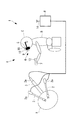
本実施形態に係るマニピュレータシステム1は、図1に示されるように、患者Aの体内に挿入されるマニピュレータ2と、該マニピュレータ2の映像を撮影する内視鏡(観察装置)3と、本実施形態に係る操作入力装置4とを備えている。
An operation input device and a manipulator system according to an embodiment of the present invention will be described below with reference to the drawings.
As shown in FIG. 1, a manipulator system 1 according to the present embodiment includes a
マニピュレータ2は、図1に示す例では、2つ設けられ、それぞれモータ2aによって、その姿勢や位置や作動状態をそれぞれ変化させることができるようになっている。また、内視鏡3もモータ3aによって、その姿勢や位置や作動状態を変化させることができるようになっている。
In the example shown in FIG. 1, two
本実施形態に係る操作入力装置4は、内視鏡3により取得された患者Aの体内におけるマニピュレータ2の映像を表示する表示部(ディスプレイ)5を備え、操作者Bの頭部Cに装着される頭部装着型ディスプレイ(頭部装着部:以下、HMDという。)6と、操作者Bによって操作される操作部7と、操作部7の操作によりマニピュレータ2を作動させる制御部8とを備えている。
The operation input device 4 according to the present embodiment includes a display unit (display) 5 that displays an image of the
HMD6は、操作者Bの頭部Cに装着された状態で、表示部5を操作者Bの眼前に配置するように構成されている。また、HMD6には、操作者Bの頭部Cに装着された状態で、操作者Bの頭部Cの前方を撮影可能な視野を有するCCDのような撮像部(相対位置センサ)9と、HMD6の空間座標系における加速度を検出する加速度センサ(空間センサ)10とが備えられている。
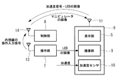
また、HMD6は、図2に示されるように、撮像部9により撮影した画像信号および加速度センサ10により検出したHMD6の空間座標系における加速度信号を無線送信する送信部11を備えている。
The
As shown in FIG. 2, the
操作部7は操作者Bが手に保持して、操作することにより、マニピュレータ2および内視鏡3を操作することができるようになっている。操作部7には、同一平面上に配置されない位置に配置されて発光する4個のLED(指標:相対位置センサ)12が固定されている。また、操作部7は、マニピュレータ2および、内視鏡3の操作入力信号を無線送信する送信部13を備えている。
The
制御部8は、内視鏡3により取得された画像信号が入力されることにより、これを処理してHMD6に送信する送受信部14を備え、HMD6に設けられた表示部5に撮影された画像を表示させるようになっている。
また、制御部8は、HMD6から無線送信されてきた画像信号および加速度信号と、操作部7から無線送信されてきた操作入力信号を受信部14により受信して、マニピュレータ2を動作させるための制御信号を生成し、生成した制御信号に基づいてマニピュレータ2のモータ2aを作動させ、マニピュレータ2を移動させあるいは作動状態を変化させるようになっている。また、これらの制御信号に基づいて内視鏡3のモータ3aを作動させ、内視鏡3を移動させあるいは作動状態を変化させることもできる。
The
In addition, the
具体的には、制御部8は、HMD6に設けられた撮像部9により取得された画像を処理して、撮像部9により撮影された操作部7上のLED12の位置および間隔によって、HMD6に対する操作部7の相対位置および相対姿勢を算出するようになっている。また、制御部8は、HMD6に設けられた加速度センサ10から出力される加速度信号に基づいて、空間座標系におけるHMD6の位置および姿勢を算出するようになっている。
Specifically, the
そして、制御部8は、HMD6に対する操作部7の相対位置および相対姿勢が変化したときには、加速度センサ10からの加速度信号によって、それがHMD6の変位によるものであるのか、操作部7の変位によるものであるのかを判定し、HMD6の変位による部分については内視鏡3を動かすための制御信号を発生させ、操作部7の変位による部分についてはマニピュレータの制御信号を発生させるようになっている。
Then, when the relative position and relative attitude of the
すなわち、HMD6を固定して操作部7を変位させた場合および操作部7を固定してHMD6を変位させた場合のいずれにおいても撮像部9により取得されたLED12の位置および間隔を変化させることができる。しかし、加速度センサ10によって検出されたHMD6の変位量分については、操作者Bが頭部Cを移動させたために発生したものであるので、このHMD6の変位量に基づいた制御信号により内視鏡3を制御し、HMD6の変位量を除いた操作部7の変位による部分を制御信号としてマニピュレータ2を作動させることができる。なお、内視鏡3の動作は、HMD6の変位にフィルタや閾値を設けて、停止や動作などの制御モードが選択できる。
That is, the position and interval of the
このように、本実施形態に係るマニピュレータシステム1および操作入力装置4によれば、操作者Bの頭部Cに装着するHMD6に、操作者Bが手に保持する操作部7のHMD6に対する相対位置および相対姿勢を検出する撮像部9を配置しているので、操作者Bが移動しても、照明や計器等の障害物によって両者間の空間が遮られず、操作部7の移動範囲が制限されることを防止することができる。すなわち、操作者Bは自由な位置で、自由な姿勢でマニピュレータ2を操作することができる。
Thus, according to the manipulator system 1 and the operation input device 4 according to the present embodiment, the relative position of the
また、HMD6に固定された操作者Bの視線座標系に対する相対的な操作部7の3次元情報をHMD6に設けた撮像部9によって直接的に取得することができる。その結果、制御部8における座標変換を軽減して、演算を高速に行うことができるという利点がある。
また、HMD6に操作者の視線を取得できる視線検出センサ18を取り付けることで、より正確な操作者の視線と操作部の相対位置が取得できる。
In addition, the three-dimensional information of the
Further, by attaching the visual
なお、本実施形態においては、相対位置センサとしてHMD6に設けた撮像部9と操作部7に設けた4個のLED12とを備えるものを例示したが、これに代えて、撮像部9を操作部7に設け、HMD6にLED12を設けることにしてもよい。
また、撮像部9を2つ設けることで、操作部7もしくはHMD6に取り付けるLEDを3点として相対位置を取得してもよい。この場合、LEDつまり指標は同一直線上に配置されない位置に配置されて固定される。また、指標は、少なくとも3箇所あればよい。
また、加速度センサ10からなる空間センサをHMD6に設けることにしたが、これに代えて、操作部7に設けることにしてもよい。
In addition, in this embodiment, what provided the
In addition, by providing two
In addition, although the spatial sensor including the
また、加速度センサ10については、HMD6および操作部7の両方に設けることにしてもよい。このようにすることで撮像部9が動作不良の場合においても操作可能とすることができ、また、一方の加速度センサ10の検出値を用いて、相対位置および相対姿勢を補正することにより、検出精度を向上することができるという利点がある。
また、加速度センサ10をHMD6および操作部7の両方に設けた場合、相対位置を撮像部9と少なくとも1つの指標とから検出し、相対姿勢を加速度センサ10により取得してもよい。
Further, the
When the
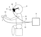
また、操作部7およびHMD6からの信号を無線送信により制御部8に送ることとしたが、これに代えて、図3に示されるように、HMD6と操作部7とを制御部8に配線15によって接続して、有線にて送信することにしてもよい。また、図4に示されるように、制御部8を操作者Bに装着することにして、さらに操作者Bの自由な移動を可能にしてもよい。
In addition, the signals from the
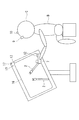
また、本実施形態においては、頭部装着部として操作者Bの眼前に配置される表示部5を有するHMD6を例示したが、これに代えて、図5に示されるように、操作者Bの頭部Cには、撮像部9と加速度センサ10のみを固定し、表示部5については、空間座標系に固定される別置き型のディスプレイ16を採用してもよい。この場合に、操作者Bの移動により、操作者Bとディスプレイ16との相対位置関係や相対角度が変化するため、表示を変更しなければ、操作者Bはディスプレイ16に表示されているマニピュレータ2の動きを脳内で変換して理解しなければならない。
Moreover, in this embodiment, although HMD6 which has the
そこで、ディスプレイ16に上記と同様のLED(ディスプレイ用指標)17を設け、操作者Bの頭部Cに設けた撮像部9と加速度センサ10とにより、操作者Bの頭部Cとディスプレイ16との相対位置関係をも検出して、表示を変更することにより、脳内で変換しなくても、操作者Bに対して常に同一の状態でマニピュレータ2の動作を表示することが可能となる。
Therefore, the
また、本実施形態においては、指標として、同一平面上に配置されない4個のLED12を例示したが、これに代えて、蛍光マーカや他の任意の指標を採用してもよい。
また、指標は5個以上設けることにしてもよい。
また、本実施形態においては、空間センサとして加速度センサ10を例示したが、これに代えてジャイロセンサや速度センサを採用してもよい。また、これらの組み合わせでもよい。
Moreover, in this embodiment, although four LED12 which is not arrange | positioned on the same plane was illustrated as an parameter | index, instead of this, you may employ | adopt a fluorescent marker and another arbitrary parameter | index.
Further, five or more indicators may be provided.
Moreover, in this embodiment, although the
A 患者
B 操作者
C 頭部
1 マニピュレータシステム
2 マニピュレータ(表示物)
3 内視鏡(観察装置)
4 操作入力装置
5 表示部(ディスプレイ)
6 HMD(頭部装着型ディスプレイ、頭部装着部)
7 操作部
8 制御部
9 撮像部(相対位置センサ)
10 加速度センサ(空間センサ)
12 LED(指標、相対位置センサ)
15 配線
16 ディスプレイ
17 指標(ディスプレイ用指標)
18 視線検出センサ
A Patient B Operator C Head 1
3 Endoscope (observation device)
4
6 HMD (head-mounted display, head-mounted part)
7
10 Acceleration sensor (space sensor)
12 LED (index, relative position sensor)
15
18 Gaze detection sensor
Claims (11)
該ディスプレイ上に表示された表示物を操作する操作部と、
操作者の頭部に装着される頭部装着部と、
該頭部装着部または前記操作部の一方に対する他方の相対位置および相対姿勢を検出する相対位置センサと、
該相対位置センサにより検出された相対位置および相対姿勢の変化に基づいて前記ディスプレイ内に表示されている表示物を作動させる制御部とを備える操作入力装置。 Display,
An operation unit for operating a display object displayed on the display;
A head mounting part to be mounted on the operator's head;
A relative position sensor that detects a relative position and a relative posture of the head mounting unit or the operation unit on the other side;
An operation input device comprising: a control unit that operates a display object displayed in the display based on a change in a relative position and a relative attitude detected by the relative position sensor.
前記表示物であるマニピュレータと、
前記ディスプレイに表示する前記表示物の映像を取得する観察装置とを備えるマニピュレータシステム。 The operation input device according to any one of claims 1 to 10,
A manipulator which is the display object;
A manipulator system comprising: an observation device that acquires an image of the display object to be displayed on the display.
Priority Applications (5)
| Application Number | Priority Date | Filing Date | Title |
|---|---|---|---|
| JP2010108344A JP5704833B2 (en) | 2010-05-10 | 2010-05-10 | Operation input device and manipulator system |
| CN201180021874.XA CN102869310B (en) | 2010-05-10 | 2011-03-04 | Operation input equipment and arm-and-hand system |
| PCT/JP2011/055050 WO2011142165A1 (en) | 2010-05-10 | 2011-03-04 | Operation input device and manipulator system |
| EP11780422.9A EP2570890A4 (en) | 2010-05-10 | 2011-03-04 | Operation input device and manipulator system |
| US13/669,801 US9361818B2 (en) | 2010-05-10 | 2012-11-06 | Operation input device and manipulator system |
Applications Claiming Priority (1)
| Application Number | Priority Date | Filing Date | Title |
|---|---|---|---|
| JP2010108344A JP5704833B2 (en) | 2010-05-10 | 2010-05-10 | Operation input device and manipulator system |
Publications (2)
| Publication Number | Publication Date |
|---|---|
| JP2011237987A true JP2011237987A (en) | 2011-11-24 |
| JP5704833B2 JP5704833B2 (en) | 2015-04-22 |
Family
ID=44914223
Family Applications (1)
| Application Number | Title | Priority Date | Filing Date |
|---|---|---|---|
| JP2010108344A Expired - Fee Related JP5704833B2 (en) | 2010-05-10 | 2010-05-10 | Operation input device and manipulator system |
Country Status (5)
| Country | Link |
|---|---|
| US (1) | US9361818B2 (en) |
| EP (1) | EP2570890A4 (en) |
| JP (1) | JP5704833B2 (en) |
| CN (1) | CN102869310B (en) |
| WO (1) | WO2011142165A1 (en) |
Cited By (8)
| Publication number | Priority date | Publication date | Assignee | Title |
|---|---|---|---|---|
| JP2013240415A (en) * | 2012-05-18 | 2013-12-05 | Olympus Corp | Surgery assistance device |
| JP2016519585A (en) * | 2013-03-15 | 2016-07-07 | エスアールアイ インターナショナルSRI International | Super elaborate surgical system |
| WO2016190057A1 (en) * | 2015-05-22 | 2016-12-01 | コニカミノルタ株式会社 | Wearable electronic device and gesture detection method for wearable electronic device |
| JP2017517297A (en) * | 2014-04-24 | 2017-06-29 | コヴィディエン リミテッド パートナーシップ | Robot interface position adjustment determination system and method |
| JP2018511359A (en) * | 2015-02-20 | 2018-04-26 | コヴィディエン リミテッド パートナーシップ | Operating room and surgical site recognition |
| WO2018143360A1 (en) * | 2017-02-03 | 2018-08-09 | 良夫 川又 | Relative position detection system and image display system |
| JP2019506922A (en) * | 2015-12-29 | 2019-03-14 | コーニンクレッカ フィリップス エヌ ヴェKoninklijke Philips N.V. | System, controller, and method for using virtual reality devices for robotic surgery |
| WO2024004941A1 (en) * | 2022-06-27 | 2024-01-04 | 川崎重工業株式会社 | Surgery support system and surgery support system control method |
Families Citing this family (34)
| Publication number | Priority date | Publication date | Assignee | Title |
|---|---|---|---|---|
| US9943372B2 (en) | 2005-04-18 | 2018-04-17 | M.S.T. Medical Surgery Technologies Ltd. | Device having a wearable interface for improving laparoscopic surgery and methods for use thereof |
| US9259289B2 (en) | 2011-05-13 | 2016-02-16 | Intuitive Surgical Operations, Inc. | Estimation of a position and orientation of a frame used in controlling movement of a tool |
| US9204939B2 (en) | 2011-08-21 | 2015-12-08 | M.S.T. Medical Surgery Technologies Ltd. | Device and method for assisting laparoscopic surgery—rule based approach |
| US11561762B2 (en) * | 2011-08-21 | 2023-01-24 | Asensus Surgical Europe S.A.R.L. | Vocally actuated surgical control system |
| US9757206B2 (en) | 2011-08-21 | 2017-09-12 | M.S.T. Medical Surgery Technologies Ltd | Device and method for assisting laparoscopic surgery—rule based approach |
| US10866783B2 (en) | 2011-08-21 | 2020-12-15 | Transenterix Europe S.A.R.L. | Vocally activated surgical control system |
| US9795282B2 (en) | 2011-09-20 | 2017-10-24 | M.S.T. Medical Surgery Technologies Ltd | Device and method for maneuvering endoscope |
| JP5993127B2 (en) * | 2011-10-25 | 2016-09-14 | オリンパス株式会社 | Head-mounted display device, information terminal, program, information storage medium, image processing system, head-mounted display device control method, and information terminal control method |
| IL221863A (en) | 2012-09-10 | 2014-01-30 | Elbit Systems Ltd | Digital system for surgical video capturing and display |
| CN103699209A (en) * | 2012-09-27 | 2014-04-02 | 联想(北京)有限公司 | Input equipment |
| US9066323B2 (en) | 2012-11-15 | 2015-06-23 | Hewlett-Packard Development Company, L.P. | Ad Hoc network connection |
| JP5549749B1 (en) * | 2013-01-16 | 2014-07-16 | 株式会社安川電機 | Robot teaching system, robot teaching program generation method and teaching tool |
| BR112015022187A2 (en) | 2013-03-14 | 2017-07-18 | Stanford Res Inst Int | minimally invasive surgical tools |
| US20150187198A1 (en) * | 2013-12-27 | 2015-07-02 | Aaron G. Silverberg | Orientation Measurement And Guidance Of Manually Positioned Objects |
| EP3166468A4 (en) * | 2014-07-10 | 2018-03-07 | M.S.T. Medical Surgery Technologies Ltd. | Improved interface for laparoscopic surgeries - movement gestures |
| KR101645392B1 (en) | 2014-08-13 | 2016-08-02 | 주식회사 고영테크놀러지 | Tracking system and tracking method using the tracking system |
| JP6788327B2 (en) | 2015-02-27 | 2020-11-25 | 株式会社ソニー・インタラクティブエンタテインメント | Display control program, display control device, and display control method |
| AU2015392228B2 (en) | 2015-04-23 | 2020-04-16 | Sri International | Hyperdexterous surgical system user interface devices |
| WO2017015599A1 (en) | 2015-07-23 | 2017-01-26 | Sri International | Robotic arm and robotic surgical system |
| ITUB20153938A1 (en) * | 2015-09-28 | 2017-03-28 | Marco Raoul Marini | Endoscopy device |
| US10786319B2 (en) * | 2015-12-29 | 2020-09-29 | Koninklijke Philips N.V. | System, control unit and method for control of a surgical robot |
| CN108698239B (en) * | 2016-02-25 | 2021-06-01 | 奥林巴斯株式会社 | Manipulator system and control method thereof |
| CN105868569A (en) * | 2016-04-15 | 2016-08-17 | 福建水立方三维数字科技有限公司 | Obstetrical nursing virtual simulation platform and operation method thereof |
| CN106175650A (en) * | 2016-06-29 | 2016-12-07 | 上海波鸿医疗器械科技有限公司 | A kind of wearing die cavity mirror virtual display system |
| CN113440263B (en) * | 2016-07-14 | 2024-03-26 | 直观外科手术操作公司 | Secondary instrument control in a computer-aided teleoperational system |
| CN106137399B (en) * | 2016-08-31 | 2018-09-04 | 北京术锐技术有限公司 | A kind of operating robot integrated control system based on embedded computer |
| WO2018078470A1 (en) * | 2016-10-25 | 2018-05-03 | Novartis Ag | Medical spatial orientation system |
| CN106781972A (en) * | 2016-12-27 | 2017-05-31 | 泉州医学高等专科学校 | Fetus based on VR technologies is shown no increases in output simulation system and the method for delivering a child |
| JP6823018B2 (en) * | 2018-08-03 | 2021-01-27 | ファナック株式会社 | Coordination support device |
| CN109498162B (en) * | 2018-12-20 | 2023-11-03 | 深圳市精锋医疗科技股份有限公司 | Main operation table for improving immersion sense and surgical robot |
| US11409091B2 (en) * | 2019-12-31 | 2022-08-09 | Carl Zeiss Meditec Ag | Method of operating a surgical microscope and surgical microscope |
| US11864841B2 (en) | 2019-12-31 | 2024-01-09 | Carl Zeiss Meditec Ag | Method of operating a surgical microscope and surgical microscope |
| US11607287B2 (en) | 2019-12-31 | 2023-03-21 | Carl Zeiss Meditec Ag | Method of operating a surgical microscope and surgical microscope |
| CN112822480B (en) | 2020-12-31 | 2022-05-17 | 青岛小鸟看看科技有限公司 | VR system and positioning tracking method thereof |
Citations (7)
| Publication number | Priority date | Publication date | Assignee | Title |
|---|---|---|---|---|
| JPH07124165A (en) * | 1993-11-02 | 1995-05-16 | Olympus Optical Co Ltd | Manupulator control system by detecting line of sight |
| JPH10127565A (en) * | 1996-10-29 | 1998-05-19 | Olympus Optical Co Ltd | Observation system for treatment in body cavity |
| JP2000102036A (en) * | 1998-09-22 | 2000-04-07 | Mr System Kenkyusho:Kk | Composite actual feeling presentation system, composite actual feeling presentation method, man-machine interface device and man-machine interface method |
| JP2000279425A (en) * | 1999-03-30 | 2000-10-10 | Olympus Optical Co Ltd | Navigation device |
| JP2002269567A (en) * | 2001-03-13 | 2002-09-20 | Canon Inc | Motion-detecting method |
| JP2005500096A (en) * | 2001-06-13 | 2005-01-06 | ヴォリューム・インタラクションズ・プライヴェート・リミテッド | Guide system |
| JP2008500624A (en) * | 2004-05-24 | 2008-01-10 | 3ディー フォー オール シャミタステクニカイ フェリャズト ケーエフティー | System and method for operating in a virtual three-dimensional space and system for selecting operations via a visualization system |
Family Cites Families (9)
| Publication number | Priority date | Publication date | Assignee | Title |
|---|---|---|---|---|
| JPH07110735A (en) | 1993-10-14 | 1995-04-25 | Nippon Telegr & Teleph Corp <Ntt> | Fitting type pen input device |
| JP3610110B2 (en) | 1995-02-23 | 2005-01-12 | オリンパス株式会社 | Medical manipulator |
| CN1373969A (en) * | 1999-07-13 | 2002-10-09 | 瑟吉维森有限公司 | Stereoscopic video observation and image magnification system |
| JP3273038B2 (en) * | 1999-11-17 | 2002-04-08 | 株式会社ナムコ | Virtual experience type game device |
| WO2001056007A1 (en) * | 2000-01-28 | 2001-08-02 | Intersense, Inc. | Self-referenced tracking |
| CN1676286A (en) * | 2004-04-02 | 2005-10-05 | 李朝辉 | Biological information follow-up instant-teaching control robot |
| US7763015B2 (en) * | 2005-01-24 | 2010-07-27 | Intuitive Surgical Operations, Inc. | Modular manipulator support for robotic surgery |
| US7907166B2 (en) * | 2005-12-30 | 2011-03-15 | Intuitive Surgical Operations, Inc. | Stereo telestration for robotic surgery |
| GB2464092A (en) * | 2008-09-25 | 2010-04-07 | Prosurgics Ltd | Surgical mechanism control system |
-
2010
- 2010-05-10 JP JP2010108344A patent/JP5704833B2/en not_active Expired - Fee Related
-
2011
- 2011-03-04 CN CN201180021874.XA patent/CN102869310B/en active Active
- 2011-03-04 WO PCT/JP2011/055050 patent/WO2011142165A1/en active Application Filing
- 2011-03-04 EP EP11780422.9A patent/EP2570890A4/en not_active Withdrawn
-
2012
- 2012-11-06 US US13/669,801 patent/US9361818B2/en active Active
Patent Citations (7)
| Publication number | Priority date | Publication date | Assignee | Title |
|---|---|---|---|---|
| JPH07124165A (en) * | 1993-11-02 | 1995-05-16 | Olympus Optical Co Ltd | Manupulator control system by detecting line of sight |
| JPH10127565A (en) * | 1996-10-29 | 1998-05-19 | Olympus Optical Co Ltd | Observation system for treatment in body cavity |
| JP2000102036A (en) * | 1998-09-22 | 2000-04-07 | Mr System Kenkyusho:Kk | Composite actual feeling presentation system, composite actual feeling presentation method, man-machine interface device and man-machine interface method |
| JP2000279425A (en) * | 1999-03-30 | 2000-10-10 | Olympus Optical Co Ltd | Navigation device |
| JP2002269567A (en) * | 2001-03-13 | 2002-09-20 | Canon Inc | Motion-detecting method |
| JP2005500096A (en) * | 2001-06-13 | 2005-01-06 | ヴォリューム・インタラクションズ・プライヴェート・リミテッド | Guide system |
| JP2008500624A (en) * | 2004-05-24 | 2008-01-10 | 3ディー フォー オール シャミタステクニカイ フェリャズト ケーエフティー | System and method for operating in a virtual three-dimensional space and system for selecting operations via a visualization system |
Cited By (16)
| Publication number | Priority date | Publication date | Assignee | Title |
|---|---|---|---|---|
| US10245111B2 (en) | 2012-05-18 | 2019-04-02 | Olympus Corporation | Operation support device |
| CN104284637A (en) * | 2012-05-18 | 2015-01-14 | 奥林巴斯株式会社 | Medical operation assistance device |
| JP2013240415A (en) * | 2012-05-18 | 2013-12-05 | Olympus Corp | Surgery assistance device |
| JP2016519585A (en) * | 2013-03-15 | 2016-07-07 | エスアールアイ インターナショナルSRI International | Super elaborate surgical system |
| US10383699B2 (en) | 2013-03-15 | 2019-08-20 | Sri International | Hyperdexterous surgical system |
| US10376337B2 (en) | 2013-03-15 | 2019-08-13 | Sri International | Hyperdexterous surgical system |
| US10299883B2 (en) | 2013-03-15 | 2019-05-28 | Sri International | Hyperdexterous surgical system |
| JP2017517297A (en) * | 2014-04-24 | 2017-06-29 | コヴィディエン リミテッド パートナーシップ | Robot interface position adjustment determination system and method |
| JP2018511359A (en) * | 2015-02-20 | 2018-04-26 | コヴィディエン リミテッド パートナーシップ | Operating room and surgical site recognition |
| JP2020049296A (en) * | 2015-02-20 | 2020-04-02 | コヴィディエン リミテッド パートナーシップ | Operating room and surgical site awareness |
| US10908681B2 (en) | 2015-02-20 | 2021-02-02 | Covidien Lp | Operating room and surgical site awareness |
| JP2021100690A (en) * | 2015-02-20 | 2021-07-08 | コヴィディエン リミテッド パートナーシップ | Operating room and surgical site awareness |
| WO2016190057A1 (en) * | 2015-05-22 | 2016-12-01 | コニカミノルタ株式会社 | Wearable electronic device and gesture detection method for wearable electronic device |
| JP2019506922A (en) * | 2015-12-29 | 2019-03-14 | コーニンクレッカ フィリップス エヌ ヴェKoninklijke Philips N.V. | System, controller, and method for using virtual reality devices for robotic surgery |
| WO2018143360A1 (en) * | 2017-02-03 | 2018-08-09 | 良夫 川又 | Relative position detection system and image display system |
| WO2024004941A1 (en) * | 2022-06-27 | 2024-01-04 | 川崎重工業株式会社 | Surgery support system and surgery support system control method |
Also Published As
| Publication number | Publication date |
|---|---|
| US20130063580A1 (en) | 2013-03-14 |
| US9361818B2 (en) | 2016-06-07 |
| WO2011142165A1 (en) | 2011-11-17 |
| EP2570890A1 (en) | 2013-03-20 |
| CN102869310B (en) | 2016-06-08 |
| CN102869310A (en) | 2013-01-09 |
| EP2570890A4 (en) | 2016-12-07 |
| JP5704833B2 (en) | 2015-04-22 |
Similar Documents
| Publication | Publication Date | Title |
|---|---|---|
| JP5704833B2 (en) | Operation input device and manipulator system | |
| JP5530234B2 (en) | Operation input device and manipulator system | |
| US20180263710A1 (en) | Medical imaging apparatus and surgical navigation system | |
| US11534246B2 (en) | User input device for use in robotic surgery | |
| US11278369B2 (en) | Control device, control method, and surgical system | |
| KR101705921B1 (en) | Synthetic representation of a surgical robot | |
| JP6264087B2 (en) | Display control device, display device, and display control system | |
| US10474411B2 (en) | System and method for alerting VR headset user to real-world objects | |
| US10134185B2 (en) | Endoscopic surgery assisting system using head-mounted displays and associated methodology | |
| JP2012223363A (en) | Surgical imaging system and surgical robot | |
| JP2021194539A (en) | Camera tracking bar for computer assisted navigation during surgery | |
| EP3163407B1 (en) | Method and apparatus for alerting to head mounted display user | |
| CN110177518A (en) | System and method for the detection object in the visual field of image capture apparatus | |
| JP2017100206A (en) | Robot safety system | |
| JP2008311690A (en) | Eyeball movement controller employing principle of vestibulo-ocular reflex | |
| AU2019292458A1 (en) | Display control system, display control device, and display control method | |
| JP2016158911A5 (en) | ||
| EP3376276B1 (en) | Constant horizon 3d imaging system and related method | |
| CN115666406A (en) | System and method for determining depth perception in vivo in a surgical robotic system | |
| JP6657858B2 (en) | Robot operation system | |
| US20190090728A1 (en) | Visualization system comprising an observation apparatus and an endoscope | |
| US20220079415A1 (en) | Visualization system comprising an observation apparatus and an endoscope | |
| US20230310086A1 (en) | Camera tracking system identifying phantom markers during computer assisted surgery navigation | |
| US20230165640A1 (en) | Extended reality systems with three-dimensional visualizations of medical image scan slices | |
| JP2006051550A (en) | Position teaching device and position teaching method to mover |
Legal Events
| Date | Code | Title | Description |
|---|---|---|---|
| A621 | Written request for application examination |
Free format text: JAPANESE INTERMEDIATE CODE: A621 Effective date: 20130322 |
|
| A131 | Notification of reasons for refusal |
Free format text: JAPANESE INTERMEDIATE CODE: A131 Effective date: 20131203 |
|
| A521 | Request for written amendment filed |
Free format text: JAPANESE INTERMEDIATE CODE: A523 Effective date: 20140131 |
|
| A131 | Notification of reasons for refusal |
Free format text: JAPANESE INTERMEDIATE CODE: A131 Effective date: 20140701 |
|
| A521 | Request for written amendment filed |
Free format text: JAPANESE INTERMEDIATE CODE: A523 Effective date: 20140829 |
|
| TRDD | Decision of grant or rejection written | ||
| A01 | Written decision to grant a patent or to grant a registration (utility model) |
Free format text: JAPANESE INTERMEDIATE CODE: A01 Effective date: 20150127 |
|
| A61 | First payment of annual fees (during grant procedure) |
Free format text: JAPANESE INTERMEDIATE CODE: A61 Effective date: 20150224 |
|
| R151 | Written notification of patent or utility model registration |
Ref document number: 5704833 Country of ref document: JP Free format text: JAPANESE INTERMEDIATE CODE: R151 |
|
| S531 | Written request for registration of change of domicile |
Free format text: JAPANESE INTERMEDIATE CODE: R313531 |
|
| R350 | Written notification of registration of transfer |
Free format text: JAPANESE INTERMEDIATE CODE: R350 |
|
| R250 | Receipt of annual fees |
Free format text: JAPANESE INTERMEDIATE CODE: R250 |
|
| LAPS | Cancellation because of no payment of annual fees |