JP2011230038A - Water treatment apparatus - Google Patents
Water treatment apparatus Download PDFInfo
- Publication number
- JP2011230038A JP2011230038A JP2010101393A JP2010101393A JP2011230038A JP 2011230038 A JP2011230038 A JP 2011230038A JP 2010101393 A JP2010101393 A JP 2010101393A JP 2010101393 A JP2010101393 A JP 2010101393A JP 2011230038 A JP2011230038 A JP 2011230038A
- Authority
- JP
- Japan
- Prior art keywords
- water
- exchange resin
- ion exchange
- treated
- water treatment
- Prior art date
- Legal status (The legal status is an assumption and is not a legal conclusion. Google has not performed a legal analysis and makes no representation as to the accuracy of the status listed.)
- Pending
Links
Images


Landscapes
- Separation Using Semi-Permeable Membranes (AREA)
- Separation Of Suspended Particles By Flocculating Agents (AREA)
- Treatment Of Water By Ion Exchange (AREA)
- Physical Water Treatments (AREA)
- Water Treatment By Sorption (AREA)
Abstract
Description
本発明は、河川水、湖沼水、地下水、し尿、下水、廃水等の液中に含まれる溶解性及び不溶解性の不用物を除去するための水処理装置に関する。 The present invention relates to a water treatment apparatus for removing soluble and insoluble waste contained in liquids such as river water, lake water, ground water, human waste, sewage, and wastewater.
従来の水処理装置として、被処理水中に粉末活性炭を混合した後、固液分離するシステムが一般的に知られている。この方法は、被処理水中に粉末活性炭を混合攪拌し、被処理水中に有機物を粉末活性炭に吸着した後、粉末活性炭を固液分離するもので、水道施設設計指針(日本水道協会)や特許文献1等に開示されている。 As a conventional water treatment apparatus, a system for solid-liquid separation after mixing powdered activated carbon in water to be treated is generally known. This method mixes and stirs powdered activated carbon in the water to be treated, adsorbs organic matter to the powdered activated carbon, and then separates the powdered activated carbon into solid and liquid. 1 and the like.
上記のような粉末活性炭を用いた水処理装置では、有機物、特にトリハロメタン生成能(THMFP)の除去に関し以下の問題が挙げられる。第一に、活性炭は基本的にイオン状物質を除去することはできないため、トリハロメタンの生成に大きく関与する被処理水中の臭化物イオンを除去することはできない。第二に、粉末活性炭は比較的多量に消費するものでありながら、使い捨てであり、長期連続使用する場合にはランニングコストを抑えるためにできるだけ使用量を低減する必要がある。 In the water treatment apparatus using the powdered activated carbon as described above, the following problems are associated with the removal of organic substances, particularly trihalomethane generation ability (THMFP). First, since activated carbon cannot basically remove ionic substances, it cannot remove bromide ions in water to be treated, which are greatly involved in the production of trihalomethanes. Secondly, powdered activated carbon is consumed in a relatively large amount, but is disposable, and when used continuously for a long period of time, it is necessary to reduce the amount of use as much as possible in order to reduce running costs.
そこで、本発明は、上記これらの課題の内少なくともいずれか一つを解決することができる水処理装置を提供することを目的とする。 Then, an object of this invention is to provide the water treatment apparatus which can solve at least any one of the said subjects.
本発明は、被処理水の不用物を固液分離する水処理装置であって、前記被処理水と粉末イオン交換樹脂と粉末活性炭とを混合させる混合手段と、前記粉末イオン交換樹脂及び前記粉末活性炭を含む被処理水の固液分離を行う固液分離手段と、を備える。 The present invention is a water treatment apparatus for solid-liquid separation of waste water to be treated, which comprises mixing means for mixing the water to be treated, powder ion exchange resin and powdered activated carbon, the powder ion exchange resin and the powder. Solid-liquid separation means for performing solid-liquid separation of water to be treated containing activated carbon.
また、前記水処理装置において、前記粉末イオン交換樹脂は、陰イオン交換樹脂又は両性イオン交換樹脂を含むことが好ましい。 Moreover, the said water treatment apparatus WHEREIN: It is preferable that the said powder ion exchange resin contains an anion exchange resin or an amphoteric ion exchange resin.
また、前記水処理装置において、前記固液分離手段が、膜ろ過装置、凝集ろ過装置、凝集膜ろ過装置、凝集沈殿ろ過装置、凝集沈殿膜ろ過装置、加圧浮上ろ過装置、加圧浮上膜ろ過装置のいずれかであることが好ましい。 Further, in the water treatment apparatus, the solid-liquid separation means includes a membrane filtration device, a coagulation filtration device, a coagulation membrane filtration device, a coagulation sediment filtration device, a coagulation sedimentation membrane filtration device, a pressure flotation filtration device, and a pressure flotation membrane filtration. Preferably any of the devices.
また、前記水処理装置において、前記粉末イオン交換樹脂の平均粒径は30μm〜70μmの範囲であることが好ましい。 Moreover, the said water treatment apparatus WHEREIN: It is preferable that the average particle diameter of the said powder ion exchange resin is the range of 30 micrometers-70 micrometers.
本発明によれば、上記これらの課題の内少なくともいずれか一つを解決することができる。 According to the present invention, at least one of these problems can be solved.
本発明の実施形態について以下説明する。本実施形態は本発明を実施する一例であって、本発明は本実施形態に限定されるものではない。 Embodiments of the present invention will be described below. This embodiment is an example for carrying out the present invention, and the present invention is not limited to this embodiment.
図1は、本実施形態に係る水処理装置の構成の一例を示す模式図である。図1に示すように、水処理装置1は、混合手段としての混合槽10と、被処理水ライン12と、イオン交換樹脂・活性炭添加ライン14と、混合液排出ライン16と、固液分離手段としての膜ろ過装置18と、処理水排出ライン20と、を備える。混合槽10内には、攪拌装置22が設けられている。攪拌装置22は被処理水と粉末イオン交換樹脂と粉末活性炭との接触が充分に行われるものであればよく、例えば、攪拌翼を用いた攪拌、ライン攪拌、ポンプ循環等であってもよい。
FIG. 1 is a schematic diagram illustrating an example of a configuration of a water treatment device according to the present embodiment. As shown in FIG. 1, the water treatment apparatus 1 includes a
イオン交換樹脂・活性炭添加ライン14は必ずしも必要ではなく、作業者が本実施形態で用いられる粉末イオン交換樹脂及び粉末活性炭を直接混合槽10に添加してもよい。なお、詳細は後述するが粉末イオン交換樹脂及び粉末活性炭はスラリー状にして混合槽10に添加する場合もあるため、その場合には、イオン交換樹脂・活性炭添加ライン14を設置することが好ましい。
The ion exchange resin / activated
混合槽10の原水導入口(不図示)には、被処理水ライン12が接続されており、混合槽10のイオン交換樹脂・活性炭導入口(不図示)には、イオン交換樹脂・活性炭添加ライン14が接続されており、混合槽10の混合液排出口(不図示)には、混合液排出ライン16が接続されている。また、混合槽10からの混合液排出ライン16は、膜ろ過装置18の導入口(不図示)に接続されている。また、膜ろ過装置18の排出口(不図示)には処理水排出ライン20が接続されている。
A treated
以下に、本実施形態の水処理装置1による処理方法について説明する。 Below, the processing method by the water treatment apparatus 1 of this embodiment is demonstrated.
被処理水は、被処理水ライン12から混合槽10へ導入される。また、粉末イオン交換樹脂及び粉末活性炭も混合槽10に投入される。上記でも説明したように、スラリーの場合にはイオン交換樹脂・活性炭添加ライン14を通して混合槽10に添加することが好ましい。そして、混合槽10内で被処理水と粉末イオン交換樹脂及び粉末活性炭が攪拌接触され、被処理水の不用物が粉末イオン交換樹脂に吸着される。この粉末イオン交換樹脂により短時間で効率的に水中の不用物、特に有機物が吸着される。その後、被処理水は混合液排出ライン16から膜ろ過装置18へ供給され、膜ろ過装置18により固液分離されたろ過水が処理水として、処理水排出ライン20から排出される。
The treated water is introduced into the
本発明者らは、被処理水中の有機物、特にトリハロメタン生成能(THMFP)除去に着目し、種々の吸着剤を用いて被処理水中からTHMFPを除去する方法を試験検討した結果、粉末活性炭と粉末イオン交換樹脂を併用した場合が最も短時間で効率的に被処理水中のTHMFPを吸着できることを知見した。すなわち、粉末イオン交換樹脂がイオン交換によりトリハロメタンの構成物質である臭化物イオンを吸着、固定することができるため、粉末活性炭を単独で使用した場合と比べて、より効率的にTHMFPの除去が可能となる。通常、被処理水中に臭化物イオンが0.1mg/L以上含まれていると、THM前駆物質である有機物(TOC)を活性炭等で除去しても、完全に除去しきれいなTHM前駆物質と臭化物イオンと次亜塩素酸が結合して、臭素系THM(ブロモジクロロメタン、ジブロモクロロメタン、ブロモホルム)が比較的容易に生成してしまう。当然、THM前駆物質であるTOCを低減することによって、これら臭素系THMも低減するが、TOCの除去率に比べてTHM除去率が低いといった傾向となる。逆に、THMFPの多くがクロロホルムであれば、TOC除去率とTHMFP低減率は、同様の傾向となる。 The present inventors have paid attention to the removal of organic substances in the treated water, particularly trihalomethane generating ability (THMFP), and as a result of examining and examining the method of removing THMFP from the treated water using various adsorbents, It was found that THMFP in the water to be treated can be efficiently adsorbed in the shortest time when the ion exchange resin is used in combination. That is, since the powder ion exchange resin can adsorb and fix bromide ions, which are constituents of trihalomethane, by ion exchange, THMFP can be removed more efficiently than when powdered activated carbon is used alone. Become. Normally, when the treatment water contains 0.1 mg / L or more of bromide ions, even if the organic substances (TOC) that are THM precursors are removed with activated carbon etc., they are completely removed and clean THM precursors and bromide ions And hypochlorous acid combine to form brominated THM (bromodichloromethane, dibromochloromethane, bromoform) relatively easily. Naturally, by reducing the TOC as a THM precursor, these brominated THMs are also reduced, but the THM removal rate tends to be lower than the TOC removal rate. Conversely, if most of the THMFP is chloroform, the TOC removal rate and the THMFP reduction rate tend to be similar.
さらに、粉末イオン交換樹脂は、その吸着機構から添加量も少なくできるため、粉末活性炭と併用しても、全体の添加量は粉末活性炭を単独で使用した場合より抑えることができるため、水処理装置自体も小さくすることができ、粉末活性炭等の大量の廃棄物を出さなくて済む。 Furthermore, since the amount of powder ion-exchange resin added can be reduced due to its adsorption mechanism, the total amount added can be reduced even when used in combination with powdered activated carbon, compared with the case where powdered activated carbon is used alone. The device itself can also be made smaller, and a large amount of waste such as powdered activated carbon can be dispensed with.
粉末イオン交換樹脂は、荷電やイオン交換により有機物吸着を行うので、粉末活性炭と併用した場合は、粉末活性炭単独では取りづらいとされている親水性物質や分子量の低い物質も除去することができるため、臭気物質やフミン由来の有機物を除去することができる。また、粉末イオン交換樹脂は極性を持つことから、少量の凝集剤によって電荷中和されて容易にしかも強固に凝集するため、膜ろ過や砂ろ過等の固液分離手段により容易に分離することができる。 Powdered ion exchange resin adsorbs organic substances by charge or ion exchange, so when used in combination with powdered activated carbon, it can also remove hydrophilic substances and low molecular weight substances that are difficult to obtain with powdered activated carbon alone. Odorous substances and organic substances derived from humin can be removed. In addition, since the powder ion exchange resin has polarity, it is easily neutralized by charge neutralization with a small amount of aggregating agent, so that it can be easily separated by solid-liquid separation means such as membrane filtration or sand filtration. it can.
本実施形態では混合手段として混合槽10を例示したが、粉末イオン交換樹脂及び粉末活性炭と被処理水との接触時間を確保することができれば、槽である必要はなく、所定の距離を有する管(ライン)等であってもよい。混合槽10の形態は角型槽、丸型槽等、特に制限されるものではない。
In this embodiment, the
混合槽10は一般の凝集設備で用いられる混和槽と同様の設計を適用して良く、混合槽10内の被処理水の滞留時間は、1分以上あれば十分であるが、混合槽10内での被処理水の滞留時間が長いほど、確実に不用物を処理することができることから概ね5分〜数十分程度の範囲に設定することが好ましい。
The
本実実施形態で用いる膜ろ過装置18は、例えば、平膜型、内圧型中空糸、外圧型中空糸、モノリス型、スパイラル型等の膜モジュールにより構成されている。膜モジュールに用いられるろ過膜には、精密ろ過膜(MF)、限外ろ過膜(UF)等が適用され、各種有機素材や無機素材などの材質、各種孔径、分画の製品が選択可能である。
The
本実施形態の処理対象となる被処理水は、特に制限されるものではないが、例えば、河川水、湖沼水、地下水、し尿、下水、工業廃水等が挙げられる。また、本発明において、粉末イオン交換樹脂、粉末活性炭それぞれへの被吸着物質に制限はないが、任意の溶解性、不溶解性物質が含まれ、各種無機物、有機物化合物、イオン、懸濁物質等が挙げられる。 Although the to-be-processed water used as the process target of this embodiment is not restrict | limited in particular, For example, river water, lake water, ground water, human waste, sewage, industrial wastewater etc. are mentioned. Further, in the present invention, there are no limitations on the substances to be adsorbed on the powder ion exchange resin and powdered activated carbon, but any soluble and insoluble substances are included, and various inorganic substances, organic compounds, ions, suspended substances, etc. Is mentioned.
粉末イオン交換樹脂を混合槽10に注入する方法は、粉体をそのまま添加する方法と、スラリー液として注入する方法がある。ここで、粉末イオン交換樹脂は、一般的に製造されるイオン交換樹脂の粒体(例えば、粒径500〜700μm以上)を粉砕処理したものである。粉末イオン交換樹脂のスラリーを混合槽10に注入する場合、スラリーの濃度に制限はないが、例えば体積比で30〜50%のスラリーが作業性の点で好ましい。粉末イオン交換樹脂の添加量は、被処理水の水質によって適宜設定すればよいが、概ね0.01mg/L〜5mg/Lの範囲である。
There are two methods for injecting the powder ion exchange resin into the mixing tank 10: adding the powder as it is, and injecting it as a slurry liquid. Here, the powder ion exchange resin is obtained by pulverizing generally produced ion exchange resin granules (for example, a particle diameter of 500 to 700 μm or more). When the slurry of the powder ion exchange resin is poured into the mixing
粉末イオン交換樹脂の種類は、特に制限されるものではないが、被処理水中の不用物のうち有機物を効果的に除去することができる点で、陰イオン交換基を持つ粉末陰イオン交換樹脂又は粉末両性イオン交換樹脂であることが好ましい。これは、被処理水中の特に天然由来の有機物はマイナスに帯電していたり、陰イオンとして解離していることがほとんどであるため、上記陰イオン交換基を持つ粉末陰イオン交換樹脂又は粉末両性イオン交換樹脂によって、効率的に吸着させることができる。 The type of the powder ion exchange resin is not particularly limited, but is a powder anion exchange resin having an anion exchange group or an anion exchange group in that organic substances can be effectively removed from wastes in the water to be treated. A powder amphoteric ion exchange resin is preferred. This is because, in particular, naturally-occurring organic substances in the water to be treated are negatively charged or dissociated as anions, so that the powder anion exchange resin or powder zwitterion having the above anion exchange group It can be efficiently adsorbed by the exchange resin.
粉末イオン交換樹脂は、粒径が大きいほど比表面積が小さくなり、被処理水中の不用物(特に有機物)の除去能力が低下する場合がある。また、粒径が小さいほど沈降性が悪くなり、その後の固液分離が難しくなる傾向がある。本実施形態では、比表面積と固液分離とのバランスがよい粉末イオン交換樹脂の平均粒径は30μm〜70μmの範囲であることが好ましい。 As the particle size of the powder ion exchange resin increases, the specific surface area decreases, and the ability to remove unnecessary substances (particularly organic substances) in the water to be treated may decrease. Further, the smaller the particle size, the worse the sedimentation property, and the subsequent solid-liquid separation tends to be difficult. In the present embodiment, the average particle size of the powder ion exchange resin having a good balance between the specific surface area and the solid-liquid separation is preferably in the range of 30 μm to 70 μm.
粉末活性炭は、水処理用として一般的に用いられる粉末活性炭であれば、特に制限されるものではない。 The powdered activated carbon is not particularly limited as long as it is powdered activated carbon generally used for water treatment.
粉末活性炭を混合槽10に注入する方法は、粉体をそのまま添加する方法と、スラリー液として注入する方法がある。粉末活性炭のスラリーを混合槽10に注入する場合、スラリーの濃度に制限はないが、例えば体積比で5〜50%のスラリーが作業性の点で好ましい。粉末活性炭の添加量は、被処理水の水質によって適宜設定すればよいが、概ね0.1mg/L〜50mg/Lの範囲である。
There are two methods for injecting the powdered activated carbon into the mixing tank 10: adding the powder as it is and injecting it as a slurry liquid. When injecting the powdered activated carbon slurry into the mixing
粉末イオン交換樹脂及び粉末活性炭のスラリーを混合槽10に注入する場合、それぞれ別々のスラリーを別々の配管から混合槽10に注入してもよいし、予め粉末イオン交換樹脂及び粉末活性炭の混合スラリーを調製しておき、イオン交換樹脂・活性炭添加ライン14から混合槽10に添加してもよい。但し、混合スラリーを用いる場合には、被処理水の水質に応じて粉末活性炭と粉末イオン交換樹脂の添加率を別々に変化させることができない。
When injecting a slurry of powder ion exchange resin and powdered activated carbon into the mixing
上記でも説明したように、本実施形態の水処理装置1により処理される被処理水中の不用物の種類は特に制限されるものではないが、分子量1000以下の有機物を除去対象とする被処理水において、本実施形態の水処理装置は有効に機能する。 As described above, the type of waste in the for-treatment water treated by the water treatment apparatus 1 of the present embodiment is not particularly limited, but the for-treatment water targeted for removal of organic substances having a molecular weight of 1000 or less. In this case, the water treatment apparatus of the present embodiment functions effectively.
混合槽10内での被処理水の滞留時間は、処理水の水質によって適宜設定されればよく、特に制限されるものではないが、概ね数分から数十分程度である。
The residence time of the water to be treated in the
図2は、本実施形態の水処理装置の構成の他の一例を示す模式図である。図2に示す水処理装置2において、図1に示す水処理装置1と同様の構成については同一の符号を付し、その説明を省略する。図2に示すように、水処理装置2は、固液分離手段として凝集ろ過装置を備えている。凝集ろ過装置は、凝集槽24と、ろ過器26とを備えている。凝集槽24内には、攪拌装置28が設けられている。攪拌装置28は被処理水と粉末イオン交換樹脂との接触が充分に行われるものであればよく例えば、攪拌翼を用いた攪拌、ポンプによる攪拌等であってもよい。
FIG. 2 is a schematic diagram illustrating another example of the configuration of the water treatment apparatus of the present embodiment. In the
水処理装置2において、混合槽10からの混合液排出ライン16aは凝集槽24の混合液供給口(不図示)に接続されており、凝集槽24の凝集剤供給口(不図示)には凝集剤添加ライン30が接続されており、凝集槽24のpH調整剤供給口(不図示)には、pH調整剤添加ライン32が接続されている。凝集槽24からの混合液排出ライン16bはろ過器26の供給口(不図示)に接続されている。ろ過器26の排出口(不図示)には、処理水排出ライン20が接続されている。
In the
以下に、本実施形態の水処理装置2による処理方法について説明する。
Below, the processing method by the
被処理水は、被処理水ライン12から混合槽10へ導入される。また、粉末イオン交換樹脂も混合槽10に投入される。そして、混合槽10内で被処理水と粉末イオン交換樹脂が攪拌接触され、被処理水の不用物が粉末イオン交換樹脂に吸着される。その後、被処理水は混合液排出ライン16aから凝集槽24へ供給される。また、任意の量の凝集剤が凝集剤添加ライン30から凝集槽24に供給される。粉末イオン交換樹脂は、極性を持つことから、少量の凝集剤によっても荷電中和されて容易に且つ強固に凝集するため、その後の固液分離が容易となる。
The treated water is introduced into the mixing
また、必要に応じて、pH調整剤がpH調整剤添加ライン32から凝集槽24に供給され、pH調整が行われる。そして、凝集槽24内では、粉末イオン交換樹脂と被処理水中の懸濁物質等がマイクロフロック化された後、混合液排出ライン16bからろ過器26へ供給され、ろ過器26により固液分離される。固液分離されたろ過水が処理水として、処理水排出ライン20から排出される。
Moreover, a pH adjuster is supplied to the
凝集槽24は、粉末イオン交換樹脂を含む被処理水へ凝集剤を拡散させて、粉末イオン交換樹脂等を凝集するための槽であり、一般の凝集沈殿設備に用いられる凝集槽と同様の設計を適用することができ、凝集槽24内の被処理水の滞留時間は1〜5分程度で短絡流が生じない設備が選択されることが好ましい。ここで、本実施形態では、凝集槽24を用いているが、被処理水と凝集剤との接触時間を確保することができれば槽である必要はなく、所定の距離を有する管(ライン)等であってもよい。
The
凝集剤の添加方式は、特に制限されるものではないが、定量制御注入できる方法が好ましく、例えば、自然流下方式、インクジェット方式、ポンプ圧送式等が一般的である。凝集剤は特に制限されるものではないが、例えば、ポリ塩化アルミニウム(PAC)、硫酸バンド、塩化鉄等が挙げられる。また、必要に応じて、酸・アルカリ等のpH調整剤や、活性ケイ酸、アクリルアミド等の凝集補助剤等も使用可能である。 The method for adding the flocculant is not particularly limited, but a method capable of quantitative control injection is preferable, and for example, a natural flow method, an ink jet method, a pump pressure method, and the like are common. The flocculant is not particularly limited, and examples thereof include polyaluminum chloride (PAC), sulfate band, iron chloride and the like. Further, if necessary, pH adjusting agents such as acids and alkalis, aggregation aids such as activated silicic acid and acrylamide can be used.
ろ過器26は、(フロック化した)粉末イオン交換樹脂を含む被処理水を固液分離するためのものであり、例えば、砂ろ過器等が用いられる。砂ろ過器は、上水設備や一般産業で用いられる急速ろ過設備等が好適であり、重力式、圧力式どちらの方式も採用可能で、現地状況やろ過速度、砂層に応じて使い分けることが好ましい。
The
砂ろ過器のろ過速度は被処理水の水質に応じて決定されるが、概ね120m/日〜360m/日の範囲である。また、砂層の高さと構成はろ過速度や被処理水の水質により決定されるが、概ね全ろ層高は60cm〜80cmの範囲であり、砂層は粒径0.45mm〜0.6mmのケイ砂を使用することが好ましい。また、複層ろ過の場合、アンスラサイト、ガーネット等も使用することが好ましい。なお、アンスラサイトは、粒径0.8mm〜1.2mmの範囲のもの、ガーネットは、粒径0.3mm〜0.4mmの範囲のものが好ましい。 The filtration rate of the sand filter is determined according to the quality of the water to be treated, but is generally in the range of 120 m / day to 360 m / day. The height and composition of the sand layer are determined by the filtration rate and the quality of the water to be treated, but the total filter layer height is generally in the range of 60 cm to 80 cm, and the sand layer is silica sand having a particle size of 0.45 mm to 0.6 mm. Is preferably used. In the case of multi-layer filtration, it is preferable to use anthracite, garnet, or the like. The anthracite preferably has a particle size in the range of 0.8 mm to 1.2 mm, and the garnet preferably has a particle size in the range of 0.3 mm to 0.4 mm.
図3は、本実施形態に係る水処理装置の構成の他の一例を示す模式図である。図3に示す水処理装置3は、固液分離手段としての凝集膜ろ過装置を備えている。凝集膜ろ過装置は、凝集槽24と、膜ろ過装置18と、を備えている。このような構成でも、被処理水中の不用物の除去を効率良く行うことが可能となる。
FIG. 3 is a schematic diagram illustrating another example of the configuration of the water treatment device according to the present embodiment. The
図4は、本実施形態に係る水処理装置の構成の他の一例を示す模式図である。図4に示す水処理装置4において、図2に示す水処理装置2と同様の構成については同一の符号を付し、その説明を省略する。図4に示す水処理装置4は、固液分離手段としての凝集沈殿ろ過装置を備えている。凝集沈殿ろ過装置は、凝集槽24と、凝集槽24と連通するフロック形成槽34と、フロック形成槽34の後段に設けられる沈殿池36と、ろ過器26と、を備えている。そして、混合槽10と凝集槽24との間、フロック形成槽34と沈殿池36との間、沈殿池36とろ過器26との間は、混合液排出ライン16a,16b,16cにより接続されている。
FIG. 4 is a schematic diagram illustrating another example of the configuration of the water treatment apparatus according to the present embodiment. In the water treatment device 4 shown in FIG. 4, the same components as those in the
以下に、本実施形態の水処理装置4による処理方法について説明する。 Below, the processing method by the water treatment apparatus 4 of this embodiment is demonstrated.
被処理水は、被処理水ライン12から混合槽10へ導入される。また、粉末イオン交換樹脂も混合槽10に投入される。そして、混合槽10内で被処理水と粉末イオン交換樹脂が攪拌接触され、被処理水の不用物が粉末イオン交換樹脂に吸着される。その後、被処理水は混合液排出ライン16aから凝集槽24へ供給される。また、任意の量の凝集剤が凝集剤添加ライン30から凝集槽24に供給される。また、必要に応じて、pH調整剤がpH調整剤添加ライン32から凝集槽24に供給され、pH調整が行われる。そして、凝集槽24内では、粉末イオン交換樹脂と被処理水中の懸濁物質等がマイクロフロック化され、フロック形成槽34へ送られる。フロック形成槽34では、フロックの粗大化が行われ、フロック形成された被処理水は、混合液排出ライン16bから沈殿池36へ送られる。沈殿池36の下部の排泥ライン40からは、沈降した固形物が排泥として系外へ排出され、沈殿池の上部の上澄水は、混合液排出ライン16cからろ過器26へ供給され、ろ過器26により固液分離される。固形分離されたろ過水が処理水として、処理水排出ライン20から排出される。
The treated water is introduced into the mixing
粉末イオン交換樹脂の真比重は1.1程度であるので、フロックの沈降性も良いが、被処理水中に多くの懸濁物質を含む場合には、本実施形態のように凝集後に沈殿池36を設置し、フロックを沈降分離させてから、その後のろ過器26等による固液分離を行うことで、有機物等の除去と固液分離処理双方が良好に達成される。
Since the true specific gravity of the powder ion exchange resin is about 1.1, the flocs have good sedimentation properties. However, when a large amount of suspended matter is contained in the water to be treated, the
フロック形成槽34は、一般の凝集沈殿設備に用いられるフロック形成槽と同様の設計を適用することができ、好ましくは滞留時間が20〜40分程度で短絡流や停滞部が生じない槽が選択される。また、フロック形成槽34には、攪拌装置38が設けられている。フロック形成槽34に設置される攪拌装置38は、フロックを粗大化させるために、緩速攪拌機であることが好ましい。
The floc-forming
沈殿池36は、フロックを沈降分離できる構造であれば特に制限されるものではなく、例えば、横流式沈殿池や傾斜版沈殿池等が挙げられる。また、被処理水の懸濁物量によっては、フロック形成槽34と沈殿池36とが合わさった高速凝集沈殿池等も採用可能である。
The
図5は、本実施形態に係る水処理装置の構成の他の一例を示す模式図である。図5に示す水処理装置5は、固液分離手段として凝集沈殿膜ろ過装置を備えている。凝集沈殿膜ろ過装置は、凝集槽24と、フロック形成槽34と、沈殿池36と、膜ろ過装置18と、を備えている。このような構成でも、被処理水中の不用物の除去を効率良く行うことが可能となる。
FIG. 5 is a schematic diagram illustrating another example of the configuration of the water treatment device according to the present embodiment. The
その他の固液分離手段としては、一般的に知られている加圧浮上ろ過装置や加圧浮上膜ろ過装置等を採用することができる。加圧浮上ろ過装置はフロックを浮上分離できる構造であれば特に制限されるものではないが、例えば、特開2010−005519号で知られているような高速加圧浮上槽等も採用可能である。 As other solid-liquid separation means, a generally known pressurized flotation filtration device, a pressurized flotation membrane filtration device, or the like can be employed. The pressurization flotation device is not particularly limited as long as the floc can be floated and separated, but, for example, a high-speed pressurization flotation tank as known in Japanese Patent Application Laid-Open No. 2010-005519 can also be used. .
なお、図1〜5に示す水処理装置は、本発明で採用し得る装置の一例であって、本発明は何ら上記図示した装置に限定されるものではなく、本発明の要旨を変更しない限り、様々な態様の水処理装置を採用することができる。 The water treatment apparatus shown in FIGS. 1 to 5 is an example of an apparatus that can be used in the present invention, and the present invention is not limited to the above-illustrated apparatus at all, as long as the gist of the present invention is not changed. Various types of water treatment devices can be employed.
以上、本実施形態に係る水処理装置によれば、被処理水中に含まれる溶解性及び不溶解性の有機物、特にTHMFPの除去率が向上することができる。 As described above, according to the water treatment apparatus of the present embodiment, the removal rate of soluble and insoluble organic substances, particularly THMFP, contained in the for-treatment water can be improved.
以下、実施例および参考例を挙げ、本発明をより具体的に詳細に説明するが、本発明は、以下の実施例に限定されるものではない。 Hereinafter, although an example and a reference example are given and the present invention is explained more concretely in detail, the present invention is not limited to the following examples.
実施例では、図3の水処理装置を用いて、以下の条件で工業用水の処理を行った。 In the examples, the industrial water was treated under the following conditions using the water treatment apparatus of FIG.
<粉末イオン交換樹脂>
実施例の粉末イオン交換樹脂には、平均粒径0.59mm〜0.70mmのイオン交換樹脂(IRA402BL(OH)−HG、ロームアンドハース社製)を平均粒径約40μmに破砕したものを用いた。実施例の粉末活性炭はダイヤホープ6MW(三菱化学カルゴン製)を用いた。そして、混合槽へ粉末イオン交換樹脂を1mg/L、粉末活性炭を5mg/L添加した。
<Powder ion exchange resin>
For the powder ion exchange resin of the examples, an ion exchange resin having an average particle size of 0.59 mm to 0.70 mm (IRA402BL (OH) -HG, manufactured by Rohm and Haas) was crushed to an average particle size of about 40 μm. It was. Diamond Hope 6 MW (manufactured by Mitsubishi Chemical Calgon) was used as the powdered activated carbon in the examples. And 1 mg / L of powder ion exchange resin and 5 mg / L of powdered activated carbon were added to the mixing tank.
<混合槽>
混合槽容量:40L
攪拌速度:120rpm
被処理水流量:206L/h
被処理水の滞留時間:11min
<凝集槽>
凝集槽容量:40L
攪拌速度:120rpm
処理流量:206L/h
処理水の滞留時間:11min
凝集剤:ポリ塩化アルミニウム(PAC)
<膜ろ過装置>
ろ過膜:FE10(ダイセン・メンブレン・システムズ社製)のUF膜
ろ過流量:206L/h
<Mixing tank>
Mixing tank capacity: 40L
Stirring speed: 120rpm
Processed water flow rate: 206L / h
Residence time of treated water: 11 min
<Coagulation tank>
Coagulation tank capacity: 40L
Stirring speed: 120rpm
Processing flow rate: 206L / h
Retention time of treated water: 11 min
Flocculant: Polyaluminum chloride (PAC)
<Membrane filtration device>
Filtration membrane: FE membrane from FE10 (Daisen Membrane Systems) Filtration flow rate: 206 L / h
比較例1では、粉末活性炭のみを添加し、その添加量を5mg/Lとしたこと以外は、実施例と同様の条件で試験を行った。 In Comparative Example 1, the test was performed under the same conditions as in Example except that only powdered activated carbon was added and the addition amount was 5 mg / L.
比較例2では、粉末活性炭のみを添加し、その添加量を20mg/Lとしたこと以外は、実施例と同様の条件で試験を行った。 In Comparative Example 2, the test was performed under the same conditions as in Example except that only powdered activated carbon was added and the addition amount was 20 mg / L.
比較例3は、粉末イオン交換樹脂のみを添加し、その添加量を1mg/Lとしたこと以外は、実施例と同様の条件で試験を行った。 Comparative Example 3 was tested under the same conditions as in Example except that only powder ion exchange resin was added and the amount added was 1 mg / L.
実施例、比較例1〜3の試験結果として、表1に実施例、比較例1〜3の処理水の水質をまとめた。 As test results of Examples and Comparative Examples 1 to 3, the quality of treated water of Examples and Comparative Examples 1 to 3 is summarized in Table 1.
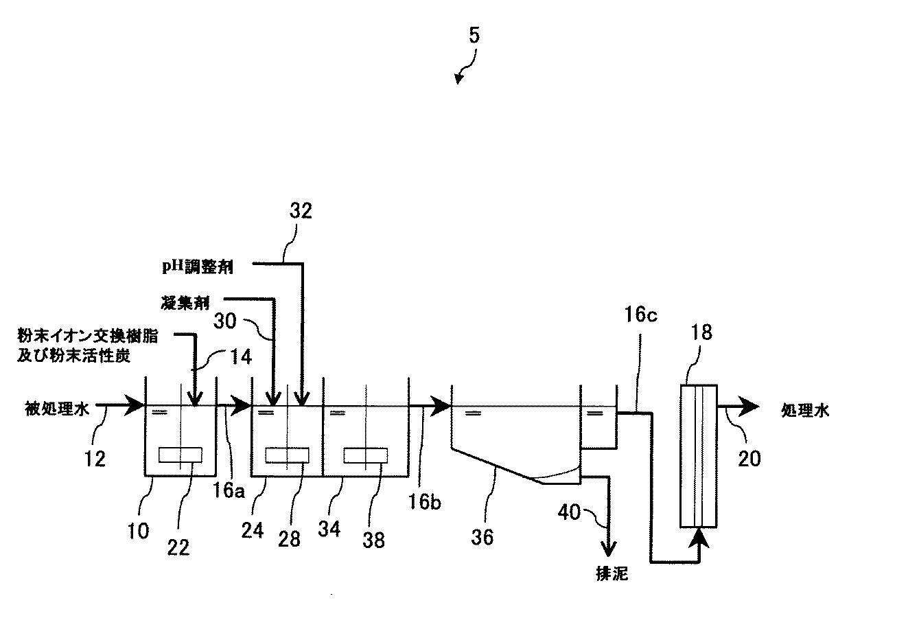
表1から判るように、実施例と比較例1〜3とを比較すると、濁度においてはほとんど差が見られなかった。色度の除去率に関しては、粉末イオン交換樹脂を添加した実施例及び比較例3の方が、粉末イオン交換樹脂を添加していない比較例1及び2より向上した。比較例3のように粉末イオン交換樹脂のみを添加するだけでも、THMFPの除去効果はある程度みられたが、実施例のように粉末イオン交換樹脂と粉末活性炭とを併用することにより、THMFPの顕著な減少が見られた。また、粉末イオン交換樹脂と粉末活性炭とを併用した場合は、それぞれ吸着しやすいTOC成分を効率的に吸着した上で、トリハロメタンの構成物質となる臭化物イオンも粉末イオン交換樹脂により除去できるため、THMFPを効果的に除去できるという傾向が見られた。 As can be seen from Table 1, when Examples and Comparative Examples 1 to 3 were compared, there was almost no difference in turbidity. Regarding the removal rate of chromaticity, Example and Comparative Example 3 to which the powder ion exchange resin was added improved more than Comparative Examples 1 and 2 to which the powder ion exchange resin was not added. Even if only the powder ion exchange resin was added as in Comparative Example 3, the removal effect of THMFP was seen to some extent, but by using the powder ion exchange resin and powdered activated carbon in combination as in the example, the remarkable effect of THMFP was obtained. There was a significant decrease. When powder ion exchange resin and powdered activated carbon are used in combination, bromide ions, which constitute trihalomethane, can be removed by powder ion exchange resin after efficiently adsorbing TOC components that are easily adsorbed. There was a tendency that can be effectively removed.
1〜5 水処理装置、10 混合槽、12 被処理水ライン、14 イオン交換樹脂・活性炭添加ライン、16a,16b,16c 混合液排出ライン、18 膜ろ過装置、20 処理水排出ライン、22,28,38 攪拌装置、24 凝集槽、26 ろ過器、30 凝集剤添加ライン、32 pH調整剤添加ライン、34 フロック形成槽、36 沈殿池、40 排泥ライン。 1-5 Water treatment device, 10 Mixing tank, 12 Water to be treated line, 14 Ion exchange resin / activated carbon addition line, 16a, 16b, 16c Mixed liquid discharge line, 18 Membrane filtration device, 20 Treated water discharge line, 22, 28 , 38 Stirrer, 24 Coagulation tank, 26 Filter, 30 Coagulant addition line, 32 pH adjuster addition line, 34 Flock formation tank, 36 Sedimentation basin, 40 Waste mud line.
Claims (4)
Priority Applications (1)
| Application Number | Priority Date | Filing Date | Title |
|---|---|---|---|
| JP2010101393A JP2011230038A (en) | 2010-04-26 | 2010-04-26 | Water treatment apparatus |
Applications Claiming Priority (1)
| Application Number | Priority Date | Filing Date | Title |
|---|---|---|---|
| JP2010101393A JP2011230038A (en) | 2010-04-26 | 2010-04-26 | Water treatment apparatus |
Publications (1)
| Publication Number | Publication Date |
|---|---|
| JP2011230038A true JP2011230038A (en) | 2011-11-17 |
Family
ID=45319945
Family Applications (1)
| Application Number | Title | Priority Date | Filing Date |
|---|---|---|---|
| JP2010101393A Pending JP2011230038A (en) | 2010-04-26 | 2010-04-26 | Water treatment apparatus |
Country Status (1)
| Country | Link |
|---|---|
| JP (1) | JP2011230038A (en) |
Cited By (16)
| Publication number | Priority date | Publication date | Assignee | Title |
|---|---|---|---|---|
| JP2015003289A (en) * | 2013-06-20 | 2015-01-08 | 前澤工業株式会社 | Water treatment method and apparatus |
| JP2015504368A (en) * | 2011-11-30 | 2015-02-12 | ローム アンド ハース カンパニーRohm And Haas Company | Coke wastewater treatment |
| JP2018069242A (en) * | 2012-05-07 | 2018-05-10 | カーボン テクノロジー ホールディングス, エルエルシー | Organism-originated active carbon, and method for creating and using the same |
| JP2019013862A (en) * | 2017-07-03 | 2019-01-31 | 株式会社ウェルシィ | Water treatment method and water treatment device |
| JP2019174378A (en) * | 2018-03-29 | 2019-10-10 | オルガノ株式会社 | Measurement method and measurement device for component concentration, and water treatment method and water treatment equipment |
| US10611977B2 (en) | 2011-04-15 | 2020-04-07 | Carbon Technology Holdings, LLC | Methods and apparatus for enhancing the energy content of carbonaceous materials from pyrolysis |
| JP6713158B1 (en) * | 2019-09-30 | 2020-06-24 | 株式会社ガブリエル | Decontamination method for tritium radioactive water |
| US11213801B2 (en) | 2013-10-24 | 2022-01-04 | Carbon Technology Holdings, LLC | Methods and apparatus for producing activated carbon from biomass through carbonized ash intermediates |
| WO2022045270A1 (en) * | 2020-08-27 | 2022-03-03 | 三菱瓦斯化学株式会社 | Method for purifying compound or polymer |
| US11358119B2 (en) | 2014-01-16 | 2022-06-14 | Carbon Technology Holdings, LLC | Carbon micro-plant |
| US11413601B2 (en) | 2014-10-24 | 2022-08-16 | Carbon Technology Holdings, LLC | Halogenated activated carbon compositions and methods of making and using same |
| US11458452B2 (en) | 2014-02-24 | 2022-10-04 | Carbon Technology Holdings, LLC | Highly mesoporous activated carbon |
| US11753698B2 (en) | 2020-09-25 | 2023-09-12 | Carbon Technology Holdings, LLC | Bio-reduction of metal ores integrated with biomass pyrolysis |
| US11851723B2 (en) | 2021-02-18 | 2023-12-26 | Carbon Technology Holdings, LLC | Carbon-negative metallurgical products |
| US11932814B2 (en) | 2021-04-27 | 2024-03-19 | Carbon Technology Holdings, LLC | Biocarbon blends with optimized fixed carbon content, and methods for making and using the same |
| US11987763B2 (en) | 2021-07-09 | 2024-05-21 | Carbon Technology Holdings, LLC | Processes for producing biocarbon pellets with high fixed-carbon content and optimized reactivity, and biocarbon pellets obtained therefrom |
Citations (2)
| Publication number | Priority date | Publication date | Assignee | Title |
|---|---|---|---|---|
| JPH0580584U (en) * | 1992-04-09 | 1993-11-02 | 船井電機株式会社 | Trihalomethane removal water purifier |
| JP2006507116A (en) * | 2002-11-22 | 2006-03-02 | オテヴェ・ソシエテ・アノニム | Water treatment method using inorganic powder reagent with high specific surface area, including reagent recycling step |
-
2010
- 2010-04-26 JP JP2010101393A patent/JP2011230038A/en active Pending
Patent Citations (2)
| Publication number | Priority date | Publication date | Assignee | Title |
|---|---|---|---|---|
| JPH0580584U (en) * | 1992-04-09 | 1993-11-02 | 船井電機株式会社 | Trihalomethane removal water purifier |
| JP2006507116A (en) * | 2002-11-22 | 2006-03-02 | オテヴェ・ソシエテ・アノニム | Water treatment method using inorganic powder reagent with high specific surface area, including reagent recycling step |
Cited By (32)
| Publication number | Priority date | Publication date | Assignee | Title |
|---|---|---|---|---|
| US11091716B2 (en) | 2011-04-15 | 2021-08-17 | Carbon Technology Holdings, LLC | High-carbon biogenic reagents and uses thereof |
| US11879107B2 (en) | 2011-04-15 | 2024-01-23 | Carbon Technology Holdings, LLC | High-carbon biogenic reagents and uses thereof |
| US11674101B2 (en) | 2011-04-15 | 2023-06-13 | Carbon Technology Holdings, LLC | Process for producing high-carbon biogenic reagents |
| US11359154B2 (en) | 2011-04-15 | 2022-06-14 | Carbon Technology Holdings, LLC | Systems and apparatus for production of high-carbon biogenic reagents |
| US11286440B2 (en) | 2011-04-15 | 2022-03-29 | Carbon Technology Holdings, LLC | Methods and apparatus for enhancing the energy content of carbonaceous materials from pyrolysis |
| US10611977B2 (en) | 2011-04-15 | 2020-04-07 | Carbon Technology Holdings, LLC | Methods and apparatus for enhancing the energy content of carbonaceous materials from pyrolysis |
| US11965139B2 (en) | 2011-04-15 | 2024-04-23 | Carbon Technology Holdings, LLC | Systems and apparatus for production of high-carbon biogenic reagents |
| US10889775B2 (en) | 2011-04-15 | 2021-01-12 | Carbon Technology Holdings, LLC | Systems and apparatus for production of high-carbon biogenic reagents |
| US11959038B2 (en) | 2011-04-15 | 2024-04-16 | Carbon Technology Holdings, LLC | High-carbon biogenic reagents and uses thereof |
| US11891582B2 (en) | 2011-04-15 | 2024-02-06 | Carbon Technology Holdings, LLC | High-carbon biogenic reagents and uses thereof |
| US10982161B2 (en) | 2011-04-15 | 2021-04-20 | Carbon Technology Holdings, LLC | Process for producing high-carbon biogenic reagents |
| JP2015504368A (en) * | 2011-11-30 | 2015-02-12 | ローム アンド ハース カンパニーRohm And Haas Company | Coke wastewater treatment |
| JP2018069242A (en) * | 2012-05-07 | 2018-05-10 | カーボン テクノロジー ホールディングス, エルエルシー | Organism-originated active carbon, and method for creating and using the same |
| JP6997612B2 (en) | 2012-05-07 | 2022-01-17 | カーボン テクノロジー ホールディングス, エルエルシー | Activated carbon of biological origin and how to make and use it |
| US11285454B2 (en) | 2012-05-07 | 2022-03-29 | Carbon Technology Holdings, LLC | Biogenic activated carbon and methods of making and using same |
| JP2015003289A (en) * | 2013-06-20 | 2015-01-08 | 前澤工業株式会社 | Water treatment method and apparatus |
| US11213801B2 (en) | 2013-10-24 | 2022-01-04 | Carbon Technology Holdings, LLC | Methods and apparatus for producing activated carbon from biomass through carbonized ash intermediates |
| US11358119B2 (en) | 2014-01-16 | 2022-06-14 | Carbon Technology Holdings, LLC | Carbon micro-plant |
| US11458452B2 (en) | 2014-02-24 | 2022-10-04 | Carbon Technology Holdings, LLC | Highly mesoporous activated carbon |
| US11413601B2 (en) | 2014-10-24 | 2022-08-16 | Carbon Technology Holdings, LLC | Halogenated activated carbon compositions and methods of making and using same |
| JP2019013862A (en) * | 2017-07-03 | 2019-01-31 | 株式会社ウェルシィ | Water treatment method and water treatment device |
| JP2019174378A (en) * | 2018-03-29 | 2019-10-10 | オルガノ株式会社 | Measurement method and measurement device for component concentration, and water treatment method and water treatment equipment |
| JP7089919B2 (en) | 2018-03-29 | 2022-06-23 | オルガノ株式会社 | Component concentration measuring method and measuring device, as well as water treatment method and water treatment device |
| EP3951800A4 (en) * | 2019-09-30 | 2022-04-27 | Kabushikikaisha, Gabriel | Method for decontaminating tritium-radiation-polluted water |
| US11482347B2 (en) | 2019-09-30 | 2022-10-25 | Kabushikikaisha Gabriel | Method for decontaminating tritium radioactive contaminated water |
| WO2021064806A1 (en) * | 2019-09-30 | 2021-04-08 | 株式会社ガブリエル | Method for decontaminating tritium-radiation-polluted water |
| JP6713158B1 (en) * | 2019-09-30 | 2020-06-24 | 株式会社ガブリエル | Decontamination method for tritium radioactive water |
| WO2022045270A1 (en) * | 2020-08-27 | 2022-03-03 | 三菱瓦斯化学株式会社 | Method for purifying compound or polymer |
| US11753698B2 (en) | 2020-09-25 | 2023-09-12 | Carbon Technology Holdings, LLC | Bio-reduction of metal ores integrated with biomass pyrolysis |
| US11851723B2 (en) | 2021-02-18 | 2023-12-26 | Carbon Technology Holdings, LLC | Carbon-negative metallurgical products |
| US11932814B2 (en) | 2021-04-27 | 2024-03-19 | Carbon Technology Holdings, LLC | Biocarbon blends with optimized fixed carbon content, and methods for making and using the same |
| US11987763B2 (en) | 2021-07-09 | 2024-05-21 | Carbon Technology Holdings, LLC | Processes for producing biocarbon pellets with high fixed-carbon content and optimized reactivity, and biocarbon pellets obtained therefrom |
Similar Documents
| Publication | Publication Date | Title |
|---|---|---|
| JP2011230038A (en) | Water treatment apparatus | |
| KR100985707B1 (en) | Method and system for the treatment of liquid effluents containing pollutants in a suspension | |
| CN105800846A (en) | Method used for reverse osmosis concentrated water treatment and zero discharge, and apparatus thereof | |
| US20240140837A1 (en) | Treatment of Liquid Streams Containing High Concentrations of Solids Using Ballasted Clarification | |
| CN106517591A (en) | Reverse osmosis concentration treatment system and method | |
| JP3409322B2 (en) | Pure water production method | |
| JP2014087787A (en) | Processing method and processing device for manganese-containing water | |
| JP2014128746A (en) | Seawater desalination apparatus, seawater desalination method, and flocculant setting for seawater desalination | |
| JP6662558B2 (en) | Water treatment method and water treatment device | |
| KR20040002594A (en) | Liquid treatment method and apparatus | |
| JP5818148B2 (en) | Outside tank type membrane separation activated sludge method and activated sludge treatment equipment | |
| WO2019208532A1 (en) | Water treatment method and water treatment apparatus | |
| Thiruvenkatachari et al. | Flocculation—cross-flow microfiltration hybrid system for natural organic matter (NOM) removal using hematite as a flocculent | |
| JP2019198806A (en) | Water treatment method, and water treatment device | |
| CN214088061U (en) | Zinc-containing wastewater recycling treatment system | |
| JP2009072747A (en) | Water treatment apparatus utilizing microbubbles and water treatment method | |
| JP5023247B1 (en) | Radioactive substance removal method and removal apparatus | |
| CN206437969U (en) | A kind of reverse osmosis thick water treatment system | |
| JP3854471B2 (en) | Water purification equipment | |
| JP2568729B2 (en) | Sewage treatment equipment | |
| WO2021106570A1 (en) | Water treatment device | |
| WO2021117542A1 (en) | Water softener | |
| JP2007319764A (en) | Coagulant | |
| JP4239326B2 (en) | Insolubilized material separation method | |
| WO2019130635A1 (en) | Method and device both for treating water |
Legal Events
| Date | Code | Title | Description |
|---|---|---|---|
| A621 | Written request for application examination |
Free format text: JAPANESE INTERMEDIATE CODE: A621 Effective date: 20130111 |
|
| A977 | Report on retrieval |
Free format text: JAPANESE INTERMEDIATE CODE: A971007 Effective date: 20131211 |
|
| A131 | Notification of reasons for refusal |
Free format text: JAPANESE INTERMEDIATE CODE: A131 Effective date: 20140107 |
|
| A521 | Written amendment |
Free format text: JAPANESE INTERMEDIATE CODE: A523 Effective date: 20140306 |
|
| A02 | Decision of refusal |
Free format text: JAPANESE INTERMEDIATE CODE: A02 Effective date: 20141202 |
|
| A521 | Written amendment |
Free format text: JAPANESE INTERMEDIATE CODE: A523 Effective date: 20150302 |
|
| A911 | Transfer of reconsideration by examiner before appeal (zenchi) |
Free format text: JAPANESE INTERMEDIATE CODE: A911 Effective date: 20150309 |
|
| A912 | Removal of reconsideration by examiner before appeal (zenchi) |
Free format text: JAPANESE INTERMEDIATE CODE: A912 Effective date: 20150529 |