JP2011198002A - Object image recognition apparatus for vehicle, object image recognition method for vehicle, and computer program - Google Patents
Object image recognition apparatus for vehicle, object image recognition method for vehicle, and computer program Download PDFInfo
- Publication number
- JP2011198002A JP2011198002A JP2010063790A JP2010063790A JP2011198002A JP 2011198002 A JP2011198002 A JP 2011198002A JP 2010063790 A JP2010063790 A JP 2010063790A JP 2010063790 A JP2010063790 A JP 2010063790A JP 2011198002 A JP2011198002 A JP 2011198002A
- Authority
- JP
- Japan
- Prior art keywords
- relative angle
- target object
- vehicle
- target
- imaging
- Prior art date
- Legal status (The legal status is an assumption and is not a legal conclusion. Google has not performed a legal analysis and makes no representation as to the accuracy of the status listed.)
- Granted
Links
Images


Landscapes
- Navigation (AREA)
- Image Processing (AREA)
- Traffic Control Systems (AREA)
- Image Analysis (AREA)
Abstract
Description
本発明は、車両周辺にある対象オブジェクトを認識する車両用対象物画像認識装置、車両用対象物画像認識方法及びコンピュータプログラムに関する。 The present invention relates to a vehicle object image recognition apparatus, a vehicle object image recognition method, and a computer program for recognizing a target object around a vehicle.
従来より、地図情報やGPS等の各種センサによって特定される車両の走行情報を取得し、運転手に対する報知や、運転の補助を行う運転支援装置について提案されている。このような運転支援装置としては、例えばナビゲーション装置の他、プリクラッシュセーフティシステム、オートクルーズコントロールシステム、レーンキーピングアシストシステム等がある。 2. Description of the Related Art Conventionally, there has been proposed a driving support device that acquires vehicle traveling information specified by various sensors such as map information and GPS, and notifies a driver or assists driving. Examples of such a driving support device include a navigation device, a pre-crash safety system, an auto cruise control system, a lane keeping assist system, and the like.
そして、そのような運転支援装置の中には、車両の前面にカメラ等の撮像装置を設け、車両周辺にあるオブジェクト(人、物、標示等)を撮像し、撮像された画像に対して画像認識処理を実施してオブジェクトを認識し、認識結果に基づいて報知や車両の制御を行うものがある。例えば、車両周辺に位置する人や自転車等の障害物を撮像画像から認識し、認識された障害物の種類や位置に基づいて該障害物への警告を行うものがある。また、車両の前方に位置する前方車両を撮像画像から認識し、認識された前方車両との間隔に基づいてアクセルやブレーキを制御するものがある。また、車両が走行する道路上に形成された最高速度や区画線等の道路標識を撮像画像から認識し、認識された道路標識の車両に対する相対位置に基づいて車両の詳細な現在位置を特定したり、ステアリング制御を行うものがある。 In such a driving support device, an imaging device such as a camera is provided on the front surface of the vehicle, and an object (a person, an object, a sign, etc.) around the vehicle is imaged and an image of the captured image is displayed. Some perform recognition processing to recognize an object, and perform notification and vehicle control based on the recognition result. For example, there is an apparatus that recognizes an obstacle such as a person or a bicycle located around a vehicle from a captured image and warns the obstacle based on the type and position of the recognized obstacle. In addition, there is a vehicle that recognizes a forward vehicle located in front of the vehicle from a captured image and controls an accelerator and a brake based on the recognized distance from the forward vehicle. It also recognizes road signs such as maximum speed and lane markings formed on the road on which the vehicle travels from the captured image, and identifies the detailed current position of the vehicle based on the relative position of the recognized road sign to the vehicle. Or perform steering control.
ここで、車両に設置された撮像装置によりオブジェクトを撮像し、撮像された画像に基づいてオブジェクトを認識する際には以下の問題があった。即ち、道路形状や車両の走行態様によってオブジェクトに対する撮像装置の位置関係や角度が変化するので、同じオブジェクトを撮像した場合であっても撮像画像中のオブジェクトの形状が毎回変化することとなる。そこで、例えば特開平8−320990号公報には、カメラで撮像した画像から車両のナンバープレートを認識する技術において、撮像画像中のナンバープレートに含まれる車番の歪み量を検出し、検出された歪み量に基づいて車番の歪みを補正し、補正後の画像に基づいて車番を認識することについて記載されている。 Here, there are the following problems when an object is imaged by an imaging device installed in a vehicle and the object is recognized based on the captured image. That is, since the positional relationship and angle of the imaging device with respect to the object change depending on the road shape and the running mode of the vehicle, the shape of the object in the captured image changes every time even when the same object is imaged. Therefore, for example, in Japanese Patent Application Laid-Open No. 8-320990, in a technique for recognizing a vehicle license plate from an image captured by a camera, a distortion amount of a vehicle number included in the license plate in the captured image is detected and detected. It describes correcting the distortion of the vehicle number based on the amount of distortion and recognizing the vehicle number based on the corrected image.
しかしながら上記特許文献1に記載された技術では、車番の歪み量を検出する処理と、検出された歪み量に基づいて車番の歪みを補正する処理とをそれぞれ実行した後に、画像認識処理を行うので、処理に係るCPUの負担が大きくなる問題があった。また、画像認識処理では、撮像されたオブジェクトの種類を特定する他の認識方法として、テンプレートマッチングによる方法がある。テンプレートマッチングでは、テンプレートのサイズや角度を少しずつ変化させて走査を行い撮像画像中のオブジェクトがテンプレートと一致するか否かを判定する処理を繰り返し行う必要がある。ここで、道路上にあるオブジェクトについては、撮像した際のサイズはそれほど大きく変化しないが、車両の向きや道路形状によって撮像した際のオブジェクトの角度は大きく変化する。従って、テンプレートマッチングによる画像認識処理についても、処理時間の長時間化やCPUの処理負荷の増大が問題となっていた。 However, in the technique described in Patent Document 1, the image recognition process is performed after executing the process of detecting the distortion amount of the vehicle number and the process of correcting the distortion of the vehicle number based on the detected distortion amount. Therefore, there is a problem that the burden on the CPU related to the processing becomes large. In the image recognition process, there is a template matching method as another recognition method for specifying the type of captured object. In template matching, it is necessary to perform scanning by changing the size and angle of the template little by little to repeatedly determine whether an object in the captured image matches the template. Here, the size of the object on the road does not change so much, but the angle of the object when imaged changes greatly depending on the direction of the vehicle and the shape of the road. Therefore, in the image recognition processing by template matching, the processing time is prolonged and the processing load on the CPU is increased.
本発明は前記従来における問題点を解消するためになされたものであり、認識対象となる対象オブジェクトについて、予め基準オブジェクトに対する相対角度をデータベース化することによって、その後に対象オブジェクトを検出する為の画像認識処理を実行する場合において、撮像装置に対する該対象オブジェクトの相対角度を予め把握することが可能となり、従来より簡易な処理によって画像認識処理を実行することを可能とした車両用対象物画像認識装置、車両用対象物画像認識方法及びコンピュータプログラムを提供することを目的とする。 The present invention has been made in order to solve the above-described problems in the related art. For a target object to be recognized, an image for detecting a target object after the relative angle with respect to a reference object is previously stored in a database. When executing recognition processing, it is possible to grasp in advance the relative angle of the target object with respect to the imaging device, and it is possible to execute image recognition processing by simpler processing than before. An object of the present invention is to provide a vehicle object image recognition method and a computer program.
前記目的を達成するため本願の請求項1に係る車両用対象物画像認識装置(1)は、車両に設置された撮像装置(19)により前記車両の周辺を撮像する撮像手段(13)と、前記撮像手段により撮像された撮像画像中に含まれる基準オブジェクト(52)の前記撮像装置に対する相対角度を基準相対角度として検出する基準相対角度検出手段(13)と、前記撮像手段により撮像された撮像画像中に含まれる対象オブジェクト(51)の前記撮像装置に対する相対角度を対象相対角度として検出する対象相対角度検出手段(13)と、前記基準相対角度と前記対象相対角度とに基づいて、前記基準オブジェクトに対する前記対象オブジェクトの相対角度を比較相対角度として算出する比較相対角度算出手段(13)と、前記比較相対角度を前記対象オブジェクトに対応づけて記憶媒体(33)に記憶する相対角度記憶手段(13)と、を有することを特徴とする。
尚、「対象オブジェクト」や「基準オブジェクト」としては、道路上又は道路付近において位置や角度が固定されている物が該当し、障害物、建造物、道路標識(路面標示含む)等がある。
In order to achieve the above object, a vehicle object image recognition device (1) according to claim 1 of the present application includes an imaging means (13) for imaging the periphery of the vehicle by an imaging device (19) installed in the vehicle, Reference relative angle detection means (13) for detecting, as a reference relative angle, a relative angle of the reference object (52) included in the captured image captured by the imaging means as a reference relative angle, and imaging captured by the imaging means Based on the target relative angle detection means (13) that detects the relative angle of the target object (51) included in the image as the target relative angle with respect to the imaging device, and based on the reference relative angle and the target relative angle, the reference A comparative relative angle calculating means (13) for calculating a relative angle of the target object with respect to the object as a comparative relative angle; The relative angle storing means for storing the serial in association with the object storage medium (33) (13), characterized in that it has a.
The “target object” and the “reference object” are objects whose positions and angles are fixed on or near the road, and include obstacles, buildings, road signs (including road markings), and the like.
また、請求項2に係る車両用対象物画像認識装置(1)は、請求項1に記載の車両用対象物画像認識装置であって、前記車両の周辺に前記対象オブジェクト(51)が位置するか否かを判定する対象オブジェクト判定手段(13)と、前記対象オブジェクト判定手段によって前記車両の周辺に前記対象オブジェクトが位置すると判定された場合に、前記撮像手段(19)により撮像された撮像画像中に含まれる基準オブジェクト(52)の前記撮像装置に対する相対角度を第1相対角度として検出する第1相対角度検出手段(13)と、前記記憶媒体(33)に記憶された前記比較相対角度の内、前記対象オブジェクト判定手段によって前記車両の周辺に位置すると判定された前記対象オブジェクトに対応づけて記憶された前記比較相対角度を抽出する角度抽出手段(13)と、前記角度抽出手段によって抽出された前記比較相対角度と前記第1相対角度とに基づいて、前記対象オブジェクト判定手段によって前記車両の周辺に位置すると判定された前記対象オブジェクトの前記撮像装置に対する相対角度を第2相対角度として検出する第2相対角度検出手段(13)と、前記第2相対角度に基づいて、前記対象オブジェクト判定手段によって前記車両の周辺に位置すると判定された前記対象オブジェクトを検出する為の前記撮像画像に対する画像認識処理を行う対象オブジェクト認識手段(13)と、を有することを特徴とする。 A vehicle object image recognition device (1) according to claim 2 is the vehicle object image recognition device according to claim 1, wherein the target object (51) is located around the vehicle. A target object determination unit (13) for determining whether or not the target object is positioned around the vehicle by the target object determination unit, and a captured image captured by the imaging unit (19) A first relative angle detecting means (13) for detecting a relative angle of the reference object (52) included in the imaging device as a first relative angle, and the comparison relative angle stored in the storage medium (33). And the comparison relative angle stored in association with the target object determined to be located around the vehicle by the target object determination means Based on the angle extracting means (13) for extracting, and the comparison relative angle and the first relative angle extracted by the angle extracting means, the target object determining means determines that the object is positioned around the vehicle. A second relative angle detection unit (13) that detects a relative angle of the target object with respect to the imaging device as a second relative angle, and based on the second relative angle, the target object determination unit is positioned around the vehicle. And target object recognition means (13) for performing image recognition processing on the captured image for detecting the determined target object.
また、請求項3に係る車両用対象物画像認識装置(1)は、車両に設置された撮像装置(19)により車両の周辺を撮像する撮像手段(13)と、基準オブジェクト(52)に対する対象オブジェクト(51)の相対角度を比較相対角度として前記対象オブジェクトに対応づけて記憶媒体(33)に記憶する相対角度記憶手段(13)と、車両の周辺に前記対象オブジェクトが位置するか否かを判定する対象オブジェクト判定手段(13)と、前記対象オブジェクト判定手段によって前記車両の周辺に前記対象オブジェクトが位置すると判定された場合に、前記撮像手段により撮像された撮像画像中に含まれる基準オブジェクトの前記撮像装置に対する相対角度を第1相対角度として検出する第1相対角度検出手段(13)と、前記記憶媒体に記憶された前記比較相対角度の内、前記対象オブジェクト判定手段によって前記車両の周辺に位置すると判定された前記対象オブジェクトに対応づけて記憶された前記比較相対角度を抽出する角度抽出手段(13)と、前記角度抽出手段によって抽出された前記比較相対角度と前記第1相対角度とに基づいて、前記対象オブジェクト判定手段によって前記車両の周辺に位置すると判定された前記対象オブジェクトの前記撮像装置に対する相対角度を第2相対角度として検出する第2相対角度検出手段(13)と、前記第2相対角度に基づいて、前記対象オブジェクト判定手段によって前記車両の周辺に位置すると判定された前記対象オブジェクトを検出する為の前記撮像画像に対する画像認識処理を行う対象オブジェクト認識手段(13)と、を有することを特徴とする。 Further, the vehicle object image recognition device (1) according to claim 3 includes an imaging means (13) for imaging the periphery of the vehicle by an imaging device (19) installed in the vehicle, and a target for the reference object (52). Relative angle storage means (13) for storing the relative angle of the object (51) as a comparative relative angle in the storage medium (33) in association with the target object, and whether or not the target object is positioned around the vehicle. When the target object determining means (13) for determining and the target object determining means determine that the target object is positioned around the vehicle, the reference object included in the captured image captured by the imaging means First relative angle detection means (13) for detecting a relative angle with respect to the imaging device as a first relative angle; and the storage medium An angle extracting means (13) for extracting the stored relative relative angle stored in association with the target object determined to be located around the vehicle by the target object determining means among the stored comparative relative angles; Based on the comparative relative angle and the first relative angle extracted by the angle extraction means, the relative angle of the target object with respect to the imaging device determined by the target object determination means to be located around the vehicle And a second relative angle detecting means (13) for detecting the target object determined to be positioned around the vehicle by the target object determining means based on the second relative angle. Target object recognition means (13) for performing image recognition processing on the captured image for the purpose , Characterized by having a.
また、請求項4に係る車両用対象物画像認識方法は、車両に設置された撮像装置(19)により車両の周辺を撮像する撮像ステップと、前記撮像ステップにより撮像された撮像画像中に含まれる基準オブジェクト(52)の前記撮像装置に対する相対角度を基準相対角度として検出する基準相対角度検出ステップと、前記撮像ステップにより撮像された撮像画像中に含まれる対象オブジェクト(51)の前記撮像装置に対する相対角度を対象相対角度として検出する対象相対角度検出ステップと、前記基準相対角度と前記対象相対角度とに基づいて、前記基準オブジェクトに対する前記対象オブジェクトの相対角度を比較相対角度として算出する比較相対角度算出ステップと、前記比較相対角度を前記対象オブジェクトに対応づけて記憶媒体(33)に記憶する相対角度記憶ステップと、を有することを特徴とする。 The vehicle object image recognition method according to claim 4 is included in an imaging step of imaging the periphery of the vehicle by an imaging device (19) installed in the vehicle, and a captured image captured by the imaging step. A reference relative angle detection step of detecting a relative angle of the reference object (52) with respect to the imaging device as a reference relative angle, and a relative of the target object (51) included in the captured image captured by the imaging step with respect to the imaging device. A target relative angle detecting step for detecting an angle as a target relative angle; and a relative relative angle calculation for calculating a relative angle of the target object with respect to the reference object as a comparative relative angle based on the reference relative angle and the target relative angle A storage medium that associates the comparison relative angle with the target object And relative angle storage step of storing in 33), characterized by having a.
更に、請求項5に係るコンピュータプログラムは、コンピュータに搭載され、車両に設置された撮像装置(19)により車両の周辺を撮像する撮像機能と、前記撮像機能により撮像された撮像画像中に含まれる基準オブジェクト(52)の前記撮像装置に対する相対角度を基準相対角度として検出する基準相対角度検出機能と、前記撮像機能により撮像された撮像画像中に含まれる対象オブジェクト(51)の前記撮像装置に対する相対角度を対象相対角度として検出する対象相対角度検出機能と、前記基準相対角度と前記対象相対角度とに基づいて、前記基準オブジェクトに対する前記対象オブジェクトの相対角度を比較相対角度として算出する比較相対角度算出機能と、前記比較相対角度を前記対象オブジェクトに対応づけて記憶媒体(33)に記憶する相対角度記憶機能と、を実行させることを特徴とする。 Furthermore, the computer program according to claim 5 is included in an image pickup function that is mounted on a computer and picks up the periphery of the vehicle by an image pickup device (19) installed in the vehicle, and a picked-up image picked up by the image pickup function. A reference relative angle detection function for detecting a relative angle of the reference object (52) with respect to the imaging device as a reference relative angle, and a relative of the target object (51) included in the captured image captured by the imaging function with respect to the imaging device. Comparative relative angle calculation that calculates a relative angle of the target object relative to the reference object based on the reference relative angle and the target relative angle based on a target relative angle detection function that detects an angle as a target relative angle. The storage medium (the function and the comparison relative angle are associated with the target object) And the relative angle storage function of storing the 3), characterized in that for the execution.
前記構成を有する請求項1に記載の車両用対象物画像認識装置では、認識対象となる対象オブジェクトについて、予め基準オブジェクトに対する相対角度をデータベース化することによって、その後に対象オブジェクトを検出する為の画像認識処理を実行する場合において、撮像装置に対する該対象オブジェクトの相対角度を予め把握することが可能となる。従って、従来より簡易な処理によって対象オブジェクトを検出する為の画像認識処理を実行することが可能となる。その結果、画像認識処理に必要となる処理時間を短時間化し、CPUの処理負荷を軽減することが可能となる。 In the vehicle object image recognition device according to claim 1 having the above-described configuration, an image for detecting a target object thereafter by creating a database of relative angles with respect to a reference object for the target object to be recognized. When executing the recognition process, the relative angle of the target object with respect to the imaging device can be grasped in advance. Therefore, it is possible to execute an image recognition process for detecting the target object by a simpler process than before. As a result, the processing time required for the image recognition process can be shortened, and the processing load on the CPU can be reduced.
また、請求項2に記載の車両用対象物画像認識装置では、データベース化された基準オブジェクトに対する対象オブジェクトの相対角度を用いることによって、認識対象とする対象オブジェクトを検出する為の画像認識処理を実行する前に、撮像装置に対する該対象オブジェクトの相対角度を予め把握することが可能となる。その結果、従来より簡易な処理によって対象オブジェクトを検出する為の画像認識処理を実行することが可能となる。 The vehicle object image recognition apparatus according to claim 2 executes an image recognition process for detecting a target object to be recognized by using a relative angle of the target object with respect to a reference object stored in a database. It is possible to grasp in advance the relative angle of the target object with respect to the imaging device. As a result, it is possible to execute an image recognition process for detecting the target object by a simpler process than before.
また、請求項3に記載の車両用対象物画像認識装置では、基準オブジェクトに対する対象オブジェクトの相対角度を記憶したデータベースを備えることによって、認識対象とする対象オブジェクトを検出する為の画像認識処理を実行する前に、撮像装置に対する該対象オブジェクトの相対角度を予め把握することが可能となる。その結果、従来より簡易な処理によって対象オブジェクトを検出する為の画像認識処理を実行することが可能となる。 In the vehicle object image recognition device according to claim 3, an image recognition process for detecting a target object to be recognized is executed by providing a database storing a relative angle of the target object with respect to the reference object. It is possible to grasp in advance the relative angle of the target object with respect to the imaging device. As a result, it is possible to execute an image recognition process for detecting the target object by a simpler process than before.
また、請求項4に記載の車両用対象物画像認識方法では、認識対象となる対象オブジェクトについて、予め基準オブジェクトに対する相対角度をデータベース化することによって、その後に対象オブジェクトを検出する為の画像認識処理を実行する場合において、撮像装置に対する該対象オブジェクトの相対角度を予め把握することが可能となる。従って、従来より簡易な処理によって対象オブジェクトを検出する為の画像認識処理を実行することが可能となる。その結果、画像認識処理に必要となる処理時間を短時間化し、CPUの処理負荷を軽減することが可能となる。 Further, in the vehicle object image recognition method according to claim 4, an image recognition process for detecting a target object after the relative angle with respect to the reference object is previously databased for the target object to be recognized. When executing the above, it is possible to grasp in advance the relative angle of the target object with respect to the imaging device. Therefore, it is possible to execute an image recognition process for detecting the target object by a simpler process than before. As a result, the processing time required for the image recognition process can be shortened, and the processing load on the CPU can be reduced.
更に、請求項5に記載のコンピュータプログラムでは、認識対象となる対象オブジェクトについて、予め基準オブジェクトに対する相対角度をデータベース化させることによって、その後に対象オブジェクトを検出する為の画像認識処理を実行させる場合において、撮像装置に対する該対象オブジェクトの相対角度を予め把握させることが可能となる。従って、従来より簡易な処理によって対象オブジェクトを検出する為の画像認識処理を実行させることが可能となる。その結果、画像認識処理に必要となる処理時間を短時間化し、CPUの処理負荷を軽減することが可能となる。 Furthermore, in the computer program according to claim 5, when a target object to be recognized is previously stored in a database as a relative angle with respect to a reference object, an image recognition process for detecting the target object is subsequently executed. The relative angle of the target object with respect to the imaging device can be grasped in advance. Therefore, it is possible to execute an image recognition process for detecting the target object by a simpler process than before. As a result, the processing time required for the image recognition process can be shortened, and the processing load on the CPU can be reduced.
以下、本発明に係る車両用対象物画像認識装置についてナビゲーション装置に具体化した一実施形態に基づき図面を参照しつつ詳細に説明する。先ず、本実施形態に係るナビゲーション装置1の概略構成について図1を用いて説明する。図1は本実施形態に係るナビゲーション装置1を示したブロック図である。 Hereinafter, a vehicle object image recognition device according to the present invention will be described in detail with reference to the drawings based on an embodiment embodied in a navigation device. First, a schematic configuration of the navigation device 1 according to the present embodiment will be described with reference to FIG. FIG. 1 is a block diagram showing a navigation device 1 according to this embodiment.
図1に示すように本実施形態に係るナビゲーション装置1は、車両の現在位置を検出する現在位置検出部11と、各種のデータが記録されたデータ記録部12と、入力された情報に基づいて、各種の演算処理を行うナビゲーションECU13と、ユーザからの操作を受け付ける操作部14と、ユーザに対して地図や目的地までの案内経路を表示する液晶ディスプレイ15と、経路案内に関する音声ガイダンスを出力するスピーカ16と、プログラムを記憶した記憶媒体であるDVDを読み取るDVDドライブ17と、交通情報センタ等の情報センタとの間で通信を行う通信モジュール18と、から構成されている。また、ナビゲーション装置1には後述する基準オブジェクト及び対象オブジェクトを検出する為のバックカメラ19が接続されている。
As shown in FIG. 1, the navigation apparatus 1 according to the present embodiment is based on a current
以下に、ナビゲーション装置1を構成する各構成要素について順に説明する。
現在位置検出部11は、GPS21、車速センサ22、ステアリングセンサ23、ジャイロセンサ24、高度計(図示せず)等からなり、現在の車両の位置、方位、車両の走行速度等を検出することが可能となっている。ここで、特に車速センサ22は、車両の移動距離や車速を検出する為のセンサであり、車両の車輪の回転に応じてパルスを発生させ、パルス信号をナビゲーションECU13に出力する。そして、ナビゲーションECU13は発生するパルスを計数することにより車輪の回転速度や移動距離を算出する。尚、上記4種類のセンサをナビゲーション装置1が全て備える必要はなく、これらの内の1又は複数種類のセンサのみをナビゲーション装置1が備える構成としても良い。
Below, each component which comprises the navigation apparatus 1 is demonstrated in order.
The current
また、データ記録部12は、外部記憶装置及び記録媒体としてのハードディスク(図示せず)と、ハードディスクに記録された地図情報DB31、路面標示DB32、オブジェクトDB33、オブジェクト識別情報34、所定のプログラム等を読み出すとともにハードディスクに所定のデータを書き込む為のドライバである記録ヘッド(図示せず)とを備えている。
The
ここで、地図情報DB31は、経路案内、交通情報案内及び地図表示に必要な各種地図データが記録されている。
また、地図データは、具体的には、道路(リンク)形状に関するリンクデータ、ノード点に関するノードデータ、施設等の地点に関する情報であるPOIデータ、各交差点に関する交差点データ、経路を探索するための探索データ、地点を検索するための検索データ、地図、道路、交通情報等の画像を液晶ディスプレイ15に描画するための画像描画データ等から構成されている。
Here, the
The map data specifically includes link data relating to road (link) shape, node data relating to node points, POI data which is information relating to points such as facilities, intersection data relating to each intersection, and search for searching for a route. Data, search data for searching for points, maps, roads, traffic information, and other images are composed of image drawing data for drawing on the
また、路面標示DB32は、路面上に形成されたオブジェクトである路面標示に関する路面表示情報が記憶されたDBである。ここで、図2は路面標示DB32の記憶領域の一例を示した図である。図2に示すように、路面標示DB32は、路面標示の位置を地図上で特定する座標データと、路面上に形成された路面標示の種類(例えば、停止線、横断歩道、文字列、最高速度)を識別する為の種類情報(識別子)と、路面標示に関連付けられた制御対象物(停止線、コーナ、交差点等)と、路面標示に関連付けられた制御対象物までの道なり距離から構成される。
The
例えば、図2に示す例では、座標(x1,y1)には「横断歩道有り」の路面標示が形成されており、且つその路面標示には60m前方に制御対象物として「停止線」の路面標示が対応付けられていることを示す。そして、ナビゲーションECU13はバックカメラ19で撮像した撮像画像から路面標示DB32に記録されたいずれかの路面標示を認識した場合に、認識した路面標示に関連付けられた制御対象物までの道なり距離に基づいて車両から制御対象物までの詳細な距離を間接的に算出する。そして、算出された距離に基づいて案内や車両制御を行う。
For example, in the example shown in FIG. 2, a road marking “with a pedestrian crossing” is formed at the coordinates (x1, y1), and the road surface of the “stop line” is 60 m ahead of the road marking as a control object. Indicates that a sign is associated. Then, when the
また、オブジェクトDB33は、本実施形態の画像認識処理で認識対象となるオブジェクトである対象オブジェクトについて、比較基準となるオブジェクトである基準オブジェクトに対する相対角度が、該対象オブジェクトに対応づけて記憶されたDBである。ここで、本実施形態では、対象オブジェクトは道路の路面上に形成された路面標示(例えば、停止線、横断歩道、文字列、最高速度等)とする。また、基本オブジェクトは区画線(車道中央線、車線境界線、車道外側線等)とするが、区画線以外のオブジェクトを基本オブジェクトとしても良い。ここで、図3はオブジェクトDB33の記憶領域の一例を示した図である。図3に示すように、オブジェクトDB33は、対象オブジェクトの位置を地図上で特定する座標データと、対象オブジェクトの種類(例えば、停止線、横断歩道、文字列、最高速度)を識別する為の種類情報(識別子)と、基準オブジェクトに対する相対角度(以下、比較相対角度という)とから構成される。
尚、基準オブジェクトは、バックカメラ19に対する相対角度が常時確実に検出できるオブジェクトとする。本実施形態では上述のように区画線(車道中央線、車線境界線、車道外側線等)を用いる。ここで、区画線は、背景である道路路面の色と明度が大きく異なる白線であって、また直線部分が多い。その結果、エッジ処理のベクトルのズレ量が小さく、角度の検出が容易になる利点がある。また、区画線は、ほとんどの道路に配置されているので、どのような道路を車両が走行する場合であっても検出できる利点がある。
The
The reference object is an object that can always reliably detect the relative angle to the
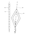
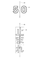
例えば、図3に示す例では、座標(x1,y1)には「横断歩道有り」の路面標示が対象オブジェクトとして存在し、且つその対象オブジェクトは基準オブジェクトに対する比較相対角度が5度であることを示す。また、比較相対角度は、対象オブジェクトの中心線と基準オブジェクトの中心線のなす角度によって定義される。ここで、図4は対象オブジェクトが「横断歩道有り」の路面標示であって、基準オブジェクトが車道外側線である場合の例である。図4に示すように、基準オブジェクト52の中心線54に対する対象オブジェクト51の中心線53の角度θが比較相対角度となる。尚、対象オブジェクト51の中心線53は、図5に示すように対象オブジェクト51の左右方向の中心を通る中心線となる。例えば、最高速度のように2つの数字が平行に並んで形成される対象オブジェクト51については、各数字の間を通る線となる。また、一の文字や記号から形成される対象オブジェクト51については、文字や記号の中心を通る線となる。尚、「止まれ」のような文字列から形成されるオブジェクトについては、文字列ではなく文字列を構成する文字毎にオブジェクトDB33に記憶しても良い。
そして、ナビゲーションECU13はオブジェクトDB33に記憶された対象オブジェクトに関する情報に基づいて、車両周辺に位置する対象オブジェクトのバックカメラ19の光軸に対する相対角度を予め検出する。そして、予め検出された相対角度に基づいてバックカメラ19で撮像した撮像画像に含まれる対象オブジェクトの簡略化した画像認識処理を行う。具体的には、パターンマッチングによる画像認識処理が行われ、その際のテンプレートマッチングにおけるテンプレートの角度の初期角度として算出された相対角度を設定して走査を開始する。
尚、路面標示DB32とオブジェクトDB33は同一のDBにより構成しても良い。
For example, in the example shown in FIG. 3, it is indicated that the road marking “with crosswalk” exists as the target object at the coordinates (x1, y1), and the target object has a comparative relative angle of 5 degrees with respect to the reference object. Show. The comparative relative angle is defined by an angle formed by the center line of the target object and the center line of the reference object. Here, FIG. 4 is an example in which the target object is a road marking “with a pedestrian crossing” and the reference object is a roadway outside line. As shown in FIG. 4, the angle θ of the
And navigation ECU13 detects previously the relative angle with respect to the optical axis of the
The
また、オブジェクト識別情報34は、路面上に形成されたオブジェクトである路面標示の画像認識処理に用いられる情報である。具体的には、路面標示の種類(例えば、停止線、横断歩道、文字列、最高速度)毎のテンプレートが記憶される。
The
一方、ナビゲーションECU(エレクトロニック・コントロール・ユニット)13は、目的地が選択された場合に現在位置から目的地までの案内経路を設定する案内経路設定処理、車両に設置されたバックカメラ19により車両の周辺を撮像する撮像処理、撮像された撮像画像中に含まれる基準オブジェクトのバックカメラ19の光軸に対する相対角度(以下、基準相対角度という)を検出する処理、撮像された撮像画像中に含まれる対象オブジェクトのバックカメラ19の光軸に対する相対角度(以下、対象相対角度という)を検出する処理、基準相対角度と対象相対角度とに基づいて、基準オブジェクトに対する対象オブジェクトの比較相対角度を算出する処理、算出された比較相対角度を対象オブジェクトに対応づけてオブジェクトDB33に記憶する処理、オブジェクトDB33に基づいて車両の周辺に位置する対象オブジェクトのバックカメラ19の光軸に対する相対角度を検出する処理、検出された相対角度に基づいて車両の周辺に位置する対象オブジェクトに対する簡略化された認識処理を行う処理、認識された対象オブジェクトに基づいて案内や車両制御を行う処理等のナビゲーション装置1の全体の制御を行う電子制御ユニットである。そして、演算装置及び制御装置としてのCPU41、並びにCPU41が各種の演算処理を行うにあたってワーキングメモリとして使用されるとともに、経路が探索されたときの経路データ等が記憶されるRAM42、制御用のプログラムのほか、後述の画像認識処理プログラム(図6、図7参照)等が記録されたROM43、ROM43から読み出したプログラムを記憶するフラッシュメモリ44等の内部記憶装置を備えている。
On the other hand, the navigation ECU (Electronic Control Unit) 13 performs a guidance route setting process for setting a guidance route from the current position to the destination when the destination is selected, and a
操作部14は、走行開始地点としての出発地及び走行終了地点としての目的地を入力する際等に操作され、各種のキー、ボタン等の複数の操作スイッチ(図示せず)から構成される。そして、ナビゲーションECU13は、各スイッチの押下等により出力されるスイッチ信号に基づき、対応する各種の動作を実行すべく制御を行う。尚、液晶ディスプレイ15の前面に設けたタッチパネルによって構成することもできる。
The
また、液晶ディスプレイ15には、道路を含む地図画像、交通情報、操作案内、操作メニュー、キーの案内、出発地から目的地までの走行予定経路、走行予定経路に沿った案内情報、ニュース、天気予報、時刻、メール、テレビ番組等が表示される。
The
また、スピーカ16は、ナビゲーションECU13からの指示に基づいて走行予定経路に沿った走行を案内する音声ガイダンスや、交通情報の案内を出力する。
Further, the
また、DVDドライブ17は、DVDやCD等の記録媒体に記録されたデータを読み取り可能なドライブである。そして、読み取ったデータに基づいて地図情報DB31や路面標示DB32の更新等が行われる。
The
また、通信モジュール18は、交通情報センタ、例えば、VICS(登録商標:Vehicle Information and Communication System)センタやプローブセンタ等から送信された渋滞情報、規制情報、交通事故情報等の各情報から成る交通情報を受信する為の通信装置であり、例えば携帯電話機やDCMが該当する。
In addition, the
また、バックカメラ19は、例えばCCD等の固体撮像素子を用いたものであり、車両の後方に装着されたナンバープレートの上中央付近に取り付けられ、視線方向を水平より所定角度下方に向けて設置される。そして、走行時に車両の進行方向と逆方向となる車両後方を撮像する。そして、撮像画像の画像認識処理を行うことによって、車両の周囲にある対象オブジェクトや基準オブジェクトの種類や位置を検出する。そして、検出された対象オブジェクトや基準オブジェクトに基づいてオブジェクトDB33を作成したり、車両から制御対象物(停止線、コーナ、交差点等)までの詳細な道なり距離を間接的に算出する。
The
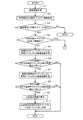
続いて、前記構成を有するナビゲーション装置1において実行する画像認識処理プログラムについて図6及び図7に基づき説明する。図6及び図7は本実施形態に係る画像認識処理プログラムのフローチャートである。ここで、画像認識処理プログラムは車両のACCがONされた後に実行され、バックカメラ19で撮像した撮像画像に基づいてオブジェクトDB33を作成するとともに、作成されたオブジェクトDB33に基づいて対象オブジェクトの簡略化した画像認識処理を行うプログラムである。尚、以下の図6、図7にフローチャートで示されるプログラムは、ナビゲーションECU13が備えているRAM42、ROM43等に記憶されており、CPU41により実行される。
Next, an image recognition processing program executed in the navigation device 1 having the above configuration will be described with reference to FIGS. 6 and 7 are flowcharts of the image recognition processing program according to the present embodiment. Here, the image recognition processing program is executed after the ACC of the vehicle is turned on, creates the
画像認識処理プログラムでは、先ずステップ(以下、Sと略記する)1において、CPU41は、車両情報を取得する。前記S1で取得される車両情報としては、車両の現在位置、車両の方位、バックカメラ19の光軸方向に関する情報がある。尚、車両の現在位置や方位については、GPS21やジャイロセンサ24の検出結果に基づいて取得する。更に、車両の現在位置については、地図情報DB31に記憶された地図情報を用いて地図上で車両の現在位置を特定するマップマッチング処理についても行う。一方、バックカメラ19の光軸方向については、車両の方位とバックカメラ19の設計値に基づいて算出される。尚、バックカメラ19の設計値についてはROM43等に記憶される。
In the image recognition processing program, first, in step (hereinafter abbreviated as S) 1, the
次に、S2でCPU41は、前記S1で取得した車両の現在位置及び方位に基づいて、車両周辺にある対象オブジェクトに関する情報を取得する。尚、本実施形態では対象オブジェクトは路面上に形成された路面標示である。従って、前記S2でCPU41は、路面標示DB32(図2参照)に記録された路面標示の位置情報に基づいて、車両の周辺(例えば、車両の前方2000m〜後方500m)に位置する路面標示の情報(路面標示の位置座標、識別子、関連付けられた制御対象物、制御対象物までの道なり距離)を路面標示DB32から読み出す。
Next, in S <b> 2, the
続いて、S3でCPU41は、前記S1で取得した車両の現在位置及び方位と前記S2で取得した対象オブジェクトに関する情報に基づいて、前記S2で情報を取得した対象オブジェクトの内、特に車両の周囲(車両の前方30m〜後方20m)に位置する対象オブジェクトがあるか否かを判定する。そして、車両の周囲に対象オブジェクトがあると判定された場合(S3:YES)には、S4へと移行する。一方、車両の周囲に対象オブジェクトがないと判定された場合(S3:NO)には、当該画像認識処理プログラムを終了する。
Subsequently, in S3, the
S4においてCPU41は、車両の周囲に位置する対象オブジェクトが、既にオブジェクトDB33(図3)に情報が記憶されている対象オブジェクトか否か判定する。そして、車両の周囲に位置する対象オブジェクトが、既にオブジェクトDB33に情報が記憶されている対象オブジェクトであると判定された場合(S4:YES)には、後述のS11へと移行する。一方、車両の周囲に位置する対象オブジェクトが、まだオブジェクトDB33に情報が記憶されていない対象オブジェクトであると判定された場合(S4:NO)には、S5へと移行する。尚、S5以降ではオブジェクトDB33の作成に関する処理が実行され、S11以降ではオブジェクトDB33を用いた対象オブジェクトの画像認識処理が実行される。
In S4, the
S5においてCPU41は、バックカメラ19により撮像された撮像画像に対して通常のパターンマッチングによる画像認識処理を実行し、撮像画像中に含まれる対象オブジェクトを検出する。尚、通常のパターンマッチングによる画像認識処理については既に公知であるので、詳細な説明は省略する。
In S <b> 5, the
次に、S6においてCPU41は、前記S5で実施された通常のパターンマッチングによる画像認識処理によって、撮像画像中に含まれる対象オブジェクトが検出でき、且つ、バックカメラ19の光軸方向に対する対象オブジェクトの相対角度(対象相対角度)αを検出できたか否か判定する。ここで、対象相対角度αは、バックカメラ19の光軸方向と対象オブジェクトの中心線のなす角度によって定義される。図8は車両61が対象オブジェクトとして「横断歩道有り」の路面標示62を検出した場合の例である。図8に示すように、バックカメラ19の光軸Lに対する路面標示62の中心線63の角度が対象相対角度αとなる。
Next, in S <b> 6, the
そして、バックカメラ19の光軸方向に対する対象オブジェクトの対象相対角度αが検出できたと判定された場合(S6:YES)には、S7へと移行する。一方、バックカメラ19の光軸方向に対する対象オブジェクトの対象相対角度αが検出できなかったと判定された場合(S6:NO)には、当該画像認識処理プログラムを終了する。
When it is determined that the target relative angle α of the target object with respect to the optical axis direction of the
S7においてCPU41は、バックカメラ19により撮像された撮像画像に対して通常の特徴点マッチングによる画像認識処理を実行し、撮像画像中に含まれる基準オブジェクトを検出する。尚、本実施形態では基準オブジェクトは路面上に形成される区画線(車道中央線、車線境界線、車道外側線等)である。尚、通常の特徴点マッチングによる画像認識処理については既に公知であるので、詳細な説明は省略する。
In S <b> 7, the
次に、S8においてCPU41は、前記S7で実施された通常の特徴点マッチングによる画像認識処理によって、撮像画像中に含まれる基準オブジェクトが検出でき、且つ、バックカメラ19の光軸方向に対する基準オブジェクトの相対角度(基準相対角度)βを検出できたか否か判定する。ここで、基準相対角度βは、バックカメラ19の光軸方向と基準オブジェクトの中心線のなす角度によって定義される。図8は車両61が基準オブジェクトとして車道外側線64を検出した場合の例である。図8に示すように、バックカメラ19の光軸Lに対する車道外側線64の中心線65の角度が基準相対角度βとなる。
Next, in S <b> 8, the
そして、バックカメラ19の光軸方向に対する基準オブジェクトの基準相対角度βが検出できたと判定された場合(S8:YES)には、S9へと移行する。一方、バックカメラ19の光軸方向に対する基準オブジェクトの基準相対角度βが検出できなかったと判定された場合(S8:NO)には、当該画像認識処理プログラムを終了する。
If it is determined that the reference relative angle β of the reference object with respect to the optical axis direction of the
S9においてCPU41は、前記S5及びS7の画像認識処理によって検出された対象相対角度αと基準相対角度βに基づいて、基準オブジェクトに対する対象オブジェクトの相対角度(比較相対角度)θを算出する。具体的には、以下の式(1)により算出される。
θ=β−α・・・・(1)
(α:対象相対角度、β:基準相対角度、θ:比較相対角度)
In S9, the
θ = β−α (1)
(Α: target relative angle, β: reference relative angle, θ: comparative relative angle)
続いて、S10においてCPU41は、前記S9で算出された比較相対角度θを検出された対象オブジェクトに対応づけてオブジェクトDB33(図3)に記憶する。それによって、オブジェクトDB33を作成する。
Subsequently, in S10, the
一方、前記S4において、車両の周囲に位置する対象オブジェクトが、既にオブジェクトDB33に情報が記憶されている対象オブジェクトであると判定された場合(S4:YES)に実行されるS11では、CPU41は、車両の周囲に位置する対象オブジェクトの情報(位置座標、識別子、比較相対角度θ)をオブジェクトDB33から取得する。
On the other hand, when it is determined in S4 that the target object located around the vehicle is a target object whose information is already stored in the object DB 33 (S4: YES), in S11, the
次に、S12においてCPU41は、バックカメラ19により撮像された撮像画像に対して通常の特徴点マッチングによる画像認識処理を実行し、撮像画像中に含まれる基準オブジェクトを検出する。尚、本実施形態では基準オブジェクトは路面上に形成される区画線(車道中央線、車線境界線、車道外側線等)である。尚、通常の特徴点マッチングによる画像認識処理については既に公知であるので、詳細な説明は省略する。
Next, in S <b> 12, the
続いて、S13においてCPU41は、前記S12で実施された通常の特徴点マッチングによる画像認識処理によって、撮像画像中に含まれる基準オブジェクトが検出でき、且つ、バックカメラ19の光軸方向に対する基準オブジェクトの相対角度(第1相対角度)γを検出できたか否か判定する。ここで、第1相対角度γは、基準相対角度βと同様にバックカメラ19の光軸方向と基準オブジェクトの中心線のなす角度によって定義される。
Subsequently, in S13, the
そして、バックカメラ19の光軸方向に対する基準オブジェクトの第1相対角度γが検出できたと判定された場合(S13:YES)には、S14へと移行する。一方、バックカメラ19の光軸方向に対する基準オブジェクトの第1相対角度γが検出できなかったと判定された場合(S13:NO)には、S16へと移行する。
If it is determined that the first relative angle γ of the reference object with respect to the optical axis direction of the
S14でCPU41は、前記S11においてオブジェクトDB33から取得した情報(位置座標、識別子、比較相対角度θ)と前記S12の画像認識処理により検出した第1相対角度γに基づいて、車両周辺に位置する対象オブジェクトのバックカメラ19の光軸方向に対する相対角度(第2相対角度)φを算出する。具体的には、以下の式(2)により算出される。
φ=γ−θ・・・・(2)
(φ:第2相対角度、γ:第1相対角度、θ:比較相対角度)
In S14, the
φ = γ−θ (2)
(Φ: second relative angle, γ: first relative angle, θ: comparative relative angle)
続いて、S15でCPU41は、前記S14で算出されたバックカメラ19の光軸方向に対する対象オブジェクトの第2相対角度φを用いて、バックカメラ19により撮像された撮像画像に対して簡略化したパターンマッチングによる画像認識処理を実行し、撮像画像中に含まれる対象オブジェクトを検出する。尚、簡略化したパターンマッチングによる画像認識処理では、テンプレートマッチングにおけるテンプレートの角度の初期角度として算出された第2相対角度φを設定して走査を開始する。そして、第2相対角度を中心にテンプレートの角度を変化させることによってテンプレートマッチングを行う。その結果、初期角度を固定角度(例えば0度)から開始する通常のパターンマッチングによる画像認識処理と比較して処理時間を簡略化することができる。また、CPU41の処理負荷も軽減することが可能となる。その後、S17の処理へと移行する。
Subsequently, in S <b> 15, the
S16においてCPU41は、バックカメラ19により撮像された撮像画像に対して通常のパターンマッチングによる画像認識処理を実行し、撮像画像中に含まれる対象オブジェクトを検出する。尚、通常のパターンマッチングによる画像認識処理については既に公知であるので、詳細な説明は省略する。その後、S17の処理へと移行する。
In S <b> 16, the
S17においてCPU41は、前記S15で実施された簡略化したパターンマッチングによる画像認識処理又は前記S16で実施された通常のパターンマッチングによる画像認識処理によって、撮像画像中に含まれる対象オブジェクトが検出できたか否か判定する。
In S17, the
そして、対象オブジェクトが検出できたと判定された場合(S17:YES)には、S18へと移行する。一方、対象オブジェクトが検出できなかったと判定された場合(S17:NO)には、当該画像認識処理プログラムを終了する。 And when it determines with the target object having been detected (S17: YES), it transfers to S18. On the other hand, if it is determined that the target object could not be detected (S17: NO), the image recognition processing program is terminated.
S18においてCPU41は、検出された対象オブジェクトに基づく案内や車両制御処理を実行する。例えば、検出された対象オブジェクトに関連付けられた制御対象物(停止線、コーナ、交差点等)までの道なり距離に基づいて車両から制御対象物までの詳細な距離を間接的に算出し、算出された距離に基づいて案内や車両制御を行う。
In S18, the
以上詳細に説明した通り、本実施形態に係るナビゲーション装置1、ナビゲーション装置1による車両用対象物画像認識方法及びナビゲーション装置1で実行されるコンピュータプログラムでは、バックカメラ19により撮像された撮像画像中に含まれる対象オブジェクトのバックカメラ19の光軸方向に対する相対角度(対象相対角度)を検出し(S5)、同じく、バックカメラ19により撮像された撮像画像中に含まれる基準オブジェクトのバックカメラ19の光軸方向に対する相対角度(基準相対角度)を検出し(S7)、検出された基準相対角度と対象相対角度とに基づいて、基準オブジェクトに対する対象オブジェクトの相対角度(比較相対角度)を算出し(S9)、算出された比較相対角度を対象オブジェクトに対応づけてオブジェクトDB33に記憶し、オブジェクトDB33を作成する(S10)。その後に、オブジェクトDB33に記憶された対象オブジェクトを検出する為の画像認識処理を実行する場合において、撮像画像中に含まれる基準オブジェクトのバックカメラ19の光軸方向に対する相対角度(第1相対角度)を検出し(S12)、検出された第1相対角度とオブジェクトDB33に記憶された比較相対角度とに基づいて対象オブジェクトのバックカメラ19の光軸方向に対する相対角度(第2相対角度)を算出し(S14)、算出された第2相対角度に基づいて、対象オブジェクトを検出する為の撮像画像に対する画像認識処理を行う(S15)ので、対象オブジェクトを検出する為の画像認識処理(S15)を実行する場合において、バックカメラ19の光軸方向に対する該対象オブジェクトの相対角度を予め把握することが可能となる。従って、従来より簡易な処理によって対象オブジェクトを検出する為の画像認識処理を実行することが可能となる。その結果、画像認識処理に必要となる処理時間を短時間化し、CPUの処理負荷を軽減することが可能となる。
尚、簡略化したパターンマッチングによる画像認識処理(S15)では、テンプレートマッチングにおけるテンプレートの角度の初期角度として算出された第2相対角度を設定して走査を開始する。そして、第2相対角度を中心にテンプレートの角度を変化させることによってテンプレートマッチングを行う。その結果、初期角度を固定角度(例えば0度)から開始する通常のパターンマッチングによる画像認識処理と比較して処理時間を簡略化することができる。
As described above in detail, in the navigation apparatus 1 according to the present embodiment, the vehicle object image recognition method using the navigation apparatus 1, and the computer program executed by the navigation apparatus 1, the captured image captured by the
In the image recognition process (S15) based on simplified pattern matching, scanning is started after setting the second relative angle calculated as the initial angle of the template angle in template matching. Then, template matching is performed by changing the angle of the template around the second relative angle. As a result, the processing time can be simplified as compared with the image recognition processing by normal pattern matching in which the initial angle is started from a fixed angle (for example, 0 degree).
尚、本発明は前記実施形態に限定されるものではなく、本発明の要旨を逸脱しない範囲内で種々の改良、変形が可能であることは勿論である。
例えば、本実施形態では、対象オブジェクトとして路面標示(停止線、横断歩道、文字列、最高速度等)を検出する構成としているが、対象オブジェクトは路面標示に限られることなく、道路上又は道路付近において位置や角度が固定されている物であればよく、障害物、建造物、他の道路標識などでも良い。
Note that the present invention is not limited to the above-described embodiment, and various improvements and modifications can be made without departing from the scope of the present invention.
For example, in this embodiment, a road marking (stop line, pedestrian crossing, character string, maximum speed, etc.) is detected as a target object. However, the target object is not limited to a road marking, but on or near a road. As long as it has a fixed position and angle, it may be an obstacle, a building, another road sign, or the like.
同じく、本実施形態では区画線を基準オブジェクトとして用いているが、道路上又は道路付近において位置や角度が固定されている物であれば他の物でも良い。また、基準オブジェクトは一種類に限定されることなく、周辺の道路形状や環境によって異なる基準オブジェクトを用いるように構成しても良い。その際には、オブジェクトDB33において基準オブジェクトを特定する情報についても比較相対角度に対応づけて記憶する必要がある。
Similarly, in the present embodiment, the lane marking is used as the reference object, but other objects may be used as long as the position and angle are fixed on or near the road. Further, the reference object is not limited to one type, and a different reference object may be used depending on the surrounding road shape and environment. In that case, it is necessary to store the information specifying the reference object in the
また、本実施形態では画像認識処理によって対象オブジェクトを検出した後に、検出された対象オブジェクトに関連付けられた制御対象物(停止線、コーナ、交差点等)までの道なり距離に基づいて車両から制御対象物までの詳細な距離を間接的に算出し、算出された距離に基づいて案内や車両制御を行うこととしているが、対象オブジェクトに基づく他の案内や車両制御を行っても良い。 In this embodiment, after the target object is detected by the image recognition process, the control target is detected from the vehicle based on the road distance to the control target object (stop line, corner, intersection, etc.) associated with the detected target object. Although a detailed distance to an object is indirectly calculated and guidance and vehicle control are performed based on the calculated distance, other guidance and vehicle control based on the target object may be performed.
また、本実施形態では、撮像装置に対する相対角度を算出する際に、バックカメラ19の光軸に対する相対角度を算出しているが、バックカメラ19に基づく他の基準方向に対する相対角度を算出しても良い。
In this embodiment, when calculating the relative angle with respect to the imaging device, the relative angle with respect to the optical axis of the
1 ナビゲーション装置
13 ナビゲーションECU
41 CPU
42 ROM
43 RAM
19 バックカメラ
33 オブジェクトDB
51 対象オブジェクト
52 基準オブジェクト
1
41 CPU
42 ROM
43 RAM
19
51
Claims (5)
前記撮像手段により撮像された撮像画像中に含まれる基準オブジェクトの前記撮像装置に対する相対角度を基準相対角度として検出する基準相対角度検出手段と、
前記撮像手段により撮像された撮像画像中に含まれる対象オブジェクトの前記撮像装置に対する相対角度を対象相対角度として検出する対象相対角度検出手段と、
前記基準相対角度と前記対象相対角度とに基づいて、前記基準オブジェクトに対する前記対象オブジェクトの相対角度を比較相対角度として算出する比較相対角度算出手段と、
前記比較相対角度を前記対象オブジェクトに対応づけて記憶媒体に記憶する相対角度記憶手段と、を有することを特徴とする車両用対象物画像認識装置。 Imaging means for imaging the periphery of the vehicle by an imaging device installed in the vehicle;
Reference relative angle detection means for detecting, as a reference relative angle, a relative angle of a reference object included in a captured image captured by the imaging means with respect to the imaging device;
Target relative angle detection means for detecting, as a target relative angle, a relative angle of a target object included in a captured image captured by the imaging means with respect to the imaging device;
Comparison relative angle calculation means for calculating a relative angle of the target object with respect to the reference object as a comparison relative angle based on the reference relative angle and the target relative angle;
Relative angle storage means for storing the comparison relative angle in a storage medium in association with the target object.
前記対象オブジェクト判定手段によって前記車両の周辺に前記対象オブジェクトが位置すると判定された場合に、前記撮像手段により撮像された撮像画像中に含まれる基準オブジェクトの前記撮像装置に対する相対角度を第1相対角度として検出する第1相対角度検出手段と、
前記記憶媒体に記憶された前記比較相対角度の内、前記対象オブジェクト判定手段によって前記車両の周辺に位置すると判定された前記対象オブジェクトに対応づけて記憶された前記比較相対角度を抽出する角度抽出手段と、
前記角度抽出手段によって抽出された前記比較相対角度と前記第1相対角度とに基づいて、前記対象オブジェクト判定手段によって前記車両の周辺に位置すると判定された前記対象オブジェクトの前記撮像装置に対する相対角度を第2相対角度として検出する第2相対角度検出手段と、
前記第2相対角度に基づいて、前記対象オブジェクト判定手段によって前記車両の周辺に位置すると判定された前記対象オブジェクトを検出する為の前記撮像画像に対する画像認識処理を行う対象オブジェクト認識手段と、を有することを特徴とする請求項1に記載の車両用対象物画像認識装置。 Target object determination means for determining whether or not the target object is located around the vehicle;
When the target object determining unit determines that the target object is located around the vehicle, the relative angle of the reference object included in the captured image captured by the imaging unit with respect to the imaging device is a first relative angle. First relative angle detecting means for detecting
Angle extracting means for extracting the comparative relative angle stored in association with the target object determined to be located around the vehicle by the target object determining means among the comparative relative angles stored in the storage medium When,
Based on the comparison relative angle and the first relative angle extracted by the angle extraction means, a relative angle of the target object determined to be positioned around the vehicle by the target object determination means is determined with respect to the imaging device. Second relative angle detection means for detecting as a second relative angle;
Target object recognition means for performing image recognition processing on the captured image for detecting the target object determined to be located around the vehicle by the target object determination means based on the second relative angle. The vehicle object image recognition apparatus according to claim 1.
基準オブジェクトに対する対象オブジェクトの相対角度を比較相対角度として前記対象オブジェクトに対応づけて記憶媒体に記憶する相対角度記憶手段と、
車両の周辺に前記対象オブジェクトが位置するか否かを判定する対象オブジェクト判定手段と、
前記対象オブジェクト判定手段によって前記車両の周辺に前記対象オブジェクトが位置すると判定された場合に、前記撮像手段により撮像された撮像画像中に含まれる基準オブジェクトの前記撮像装置に対する相対角度を第1相対角度として検出する第1相対角度検出手段と、
前記記憶媒体に記憶された前記比較相対角度の内、前記対象オブジェクト判定手段によって前記車両の周辺に位置すると判定された前記対象オブジェクトに対応づけて記憶された前記比較相対角度を抽出する角度抽出手段と、
前記角度抽出手段によって抽出された前記比較相対角度と前記第1相対角度とに基づいて、前記対象オブジェクト判定手段によって前記車両の周辺に位置すると判定された前記対象オブジェクトの前記撮像装置に対する相対角度を第2相対角度として検出する第2相対角度検出手段と、
前記第2相対角度に基づいて、前記対象オブジェクト判定手段によって前記車両の周辺に位置すると判定された前記対象オブジェクトを検出する為の前記撮像画像に対する画像認識処理を行う対象オブジェクト認識手段と、を有することを特徴とする車両用対象物画像認識装置。 Imaging means for imaging the periphery of the vehicle with an imaging device installed in the vehicle;
A relative angle storage means for storing a relative angle of the target object with respect to a reference object as a comparison relative angle in a storage medium in association with the target object;
Target object determination means for determining whether or not the target object is located around the vehicle;
When the target object determining unit determines that the target object is located around the vehicle, the relative angle of the reference object included in the captured image captured by the imaging unit with respect to the imaging device is a first relative angle. First relative angle detecting means for detecting
Angle extracting means for extracting the comparative relative angle stored in association with the target object determined to be located around the vehicle by the target object determining means among the comparative relative angles stored in the storage medium When,
Based on the comparison relative angle and the first relative angle extracted by the angle extraction means, a relative angle of the target object determined to be positioned around the vehicle by the target object determination means is determined with respect to the imaging device. Second relative angle detection means for detecting as a second relative angle;
Target object recognition means for performing image recognition processing on the captured image for detecting the target object determined to be located around the vehicle by the target object determination means based on the second relative angle. A vehicle object image recognition device characterized by the above.
前記撮像ステップにより撮像された撮像画像中に含まれる基準オブジェクトの前記撮像装置に対する相対角度を基準相対角度として検出する基準相対角度検出ステップと、
前記撮像ステップにより撮像された撮像画像中に含まれる対象オブジェクトの前記撮像装置に対する相対角度を対象相対角度として検出する対象相対角度検出ステップと、
前記基準相対角度と前記対象相対角度とに基づいて、前記基準オブジェクトに対する前記対象オブジェクトの相対角度を比較相対角度として算出する比較相対角度算出ステップと、
前記比較相対角度を前記対象オブジェクトに対応づけて記憶媒体に記憶する相対角度記憶ステップと、を有することを特徴とする車両用対象物画像認識方法。 An imaging step of imaging the periphery of the vehicle with an imaging device installed in the vehicle;
A reference relative angle detection step of detecting, as a reference relative angle, a relative angle of a reference object included in the captured image captured by the imaging step with respect to the imaging device;
A target relative angle detection step of detecting a relative angle of a target object included in the captured image captured by the imaging step with respect to the imaging device as a target relative angle;
A comparative relative angle calculation step of calculating a relative angle of the target object with respect to the reference object as a comparative relative angle based on the reference relative angle and the target relative angle;
And a relative angle storage step of storing the comparative relative angle in a storage medium in association with the target object.
車両に設置された撮像装置により車両の周辺を撮像する撮像機能と、
前記撮像機能により撮像された撮像画像中に含まれる基準オブジェクトの前記撮像装置に対する相対角度を基準相対角度として検出する基準相対角度検出機能と、
前記撮像機能により撮像された撮像画像中に含まれる対象オブジェクトの前記撮像装置に対する相対角度を対象相対角度として検出する対象相対角度検出機能と、
前記基準相対角度と前記対象相対角度とに基づいて、前記基準オブジェクトに対する前記対象オブジェクトの相対角度を比較相対角度として算出する比較相対角度算出機能と、
前記比較相対角度を前記対象オブジェクトに対応づけて記憶媒体に記憶する相対角度記憶機能と、
を実行させることを特徴とするコンピュータプログラム。
On the computer,
An imaging function for imaging the periphery of the vehicle with an imaging device installed in the vehicle;
A reference relative angle detection function for detecting, as a reference relative angle, a relative angle of a reference object included in a captured image captured by the imaging function with respect to the imaging device;
A target relative angle detection function for detecting, as a target relative angle, a relative angle of a target object included in a captured image captured by the imaging function with respect to the imaging device;
A comparative relative angle calculation function for calculating a relative angle of the target object with respect to the reference object as a comparative relative angle based on the reference relative angle and the target relative angle;
A relative angle storage function for storing the comparison relative angle in a storage medium in association with the target object;
A computer program for executing
Priority Applications (1)
| Application Number | Priority Date | Filing Date | Title |
|---|---|---|---|
| JP2010063790A JP5573266B2 (en) | 2010-03-19 | 2010-03-19 | Vehicle object image recognition apparatus, vehicle object image recognition method, and computer program |
Applications Claiming Priority (1)
| Application Number | Priority Date | Filing Date | Title |
|---|---|---|---|
| JP2010063790A JP5573266B2 (en) | 2010-03-19 | 2010-03-19 | Vehicle object image recognition apparatus, vehicle object image recognition method, and computer program |
Publications (2)
| Publication Number | Publication Date |
|---|---|
| JP2011198002A true JP2011198002A (en) | 2011-10-06 |
| JP5573266B2 JP5573266B2 (en) | 2014-08-20 |
Family
ID=44876125
Family Applications (1)
| Application Number | Title | Priority Date | Filing Date |
|---|---|---|---|
| JP2010063790A Expired - Fee Related JP5573266B2 (en) | 2010-03-19 | 2010-03-19 | Vehicle object image recognition apparatus, vehicle object image recognition method, and computer program |
Country Status (1)
| Country | Link |
|---|---|
| JP (1) | JP5573266B2 (en) |
Cited By (3)
| Publication number | Priority date | Publication date | Assignee | Title |
|---|---|---|---|---|
| JP2016162436A (en) * | 2015-03-05 | 2016-09-05 | 株式会社東芝 | Road appanage detection device and road appanage detection method |
| CN113418543A (en) * | 2019-01-16 | 2021-09-21 | 北京百度网讯科技有限公司 | Method and device for detecting automatic driving sensor, electronic equipment and storage medium |
| JP2022111187A (en) * | 2014-11-19 | 2022-07-29 | エイディシーテクノロジー株式会社 | Automatic driving control device and vehicle |
Citations (3)
| Publication number | Priority date | Publication date | Assignee | Title |
|---|---|---|---|---|
| JPH1186199A (en) * | 1997-09-10 | 1999-03-30 | Yazaki Corp | Method and device for detecting traffic lane |
| JP2005346197A (en) * | 2004-05-31 | 2005-12-15 | Toyota Motor Corp | Method and device for detecting lane boundary line, and method and device for controlling lane keeping |
| JP2007145251A (en) * | 2005-11-29 | 2007-06-14 | Aisin Aw Co Ltd | Driving support device |
-
2010
- 2010-03-19 JP JP2010063790A patent/JP5573266B2/en not_active Expired - Fee Related
Patent Citations (3)
| Publication number | Priority date | Publication date | Assignee | Title |
|---|---|---|---|---|
| JPH1186199A (en) * | 1997-09-10 | 1999-03-30 | Yazaki Corp | Method and device for detecting traffic lane |
| JP2005346197A (en) * | 2004-05-31 | 2005-12-15 | Toyota Motor Corp | Method and device for detecting lane boundary line, and method and device for controlling lane keeping |
| JP2007145251A (en) * | 2005-11-29 | 2007-06-14 | Aisin Aw Co Ltd | Driving support device |
Cited By (5)
| Publication number | Priority date | Publication date | Assignee | Title |
|---|---|---|---|---|
| JP2022111187A (en) * | 2014-11-19 | 2022-07-29 | エイディシーテクノロジー株式会社 | Automatic driving control device and vehicle |
| JP2016162436A (en) * | 2015-03-05 | 2016-09-05 | 株式会社東芝 | Road appanage detection device and road appanage detection method |
| CN113418543A (en) * | 2019-01-16 | 2021-09-21 | 北京百度网讯科技有限公司 | Method and device for detecting automatic driving sensor, electronic equipment and storage medium |
| CN113418543B (en) * | 2019-01-16 | 2023-06-20 | 北京百度网讯科技有限公司 | Automatic driving sensor detection method and device, electronic equipment and storage medium |
| US11933604B2 (en) | 2019-01-16 | 2024-03-19 | Apollo Intelligent Driving Technology (Beijing) Co., Ltd. | Detection method and apparatus for automatic driving sensor, and electronic device |
Also Published As
| Publication number | Publication date |
|---|---|
| JP5573266B2 (en) | 2014-08-20 |
Similar Documents
| Publication | Publication Date | Title |
|---|---|---|
| JP6566145B2 (en) | Driving support device and computer program | |
| JP4886597B2 (en) | Lane determination device, lane determination method, and navigation device using the same | |
| JP4421549B2 (en) | Driving assistance device | |
| JP6926976B2 (en) | Parking assistance device and computer program | |
| JP5482167B2 (en) | Vehicle travel guidance device, vehicle travel guidance method, and computer program | |
| JP5729176B2 (en) | Movement guidance system, movement guidance apparatus, movement guidance method, and computer program | |
| JP4762697B2 (en) | Vehicle driving assistance system | |
| JP2012132744A (en) | Route guidance device, route guidance method and computer program | |
| JP2019164611A (en) | Traveling support device and computer program | |
| JP4637302B2 (en) | Road marking recognition system | |
| JP4888285B2 (en) | Driving support device, driving support method, and computer program | |
| JP5573266B2 (en) | Vehicle object image recognition apparatus, vehicle object image recognition method, and computer program | |
| JP2017062706A (en) | Travel support system, travel support method, and computer program | |
| JP2010262665A (en) | On-vehicle device and vehicle recognition method | |
| JP2008262481A (en) | Vehicle control device | |
| JP2009009368A (en) | Road-surface indication recognition system | |
| JP6597128B2 (en) | Vehicle display device | |
| JP2009059209A (en) | Driving support apparatus, driving support method and computer program | |
| JP2013030006A (en) | Traffic light increase/decrease detection system, traffic light increase/decrease detection device, traffic light increase/decrease detection method, and computer program | |
| JP6582798B2 (en) | Driving support system, driving support method, and computer program | |
| JP2015007558A (en) | System of searching institution associated with parking lot, method of searching institution associated with parking lot, and computer program | |
| JP2015007557A (en) | Associated parking lot registration system, associated parking lot registration method, and computer program | |
| JP2011179920A (en) | Display control device, display control method, program, and recording medium | |
| JP5564920B2 (en) | Driving support device, driving support method, and computer program | |
| JP5712844B2 (en) | Moving body position detection system, moving body position detection apparatus, moving body position detection method, and computer program |
Legal Events
| Date | Code | Title | Description |
|---|---|---|---|
| A621 | Written request for application examination |
Free format text: JAPANESE INTERMEDIATE CODE: A621 Effective date: 20120229 |
|
| A131 | Notification of reasons for refusal |
Free format text: JAPANESE INTERMEDIATE CODE: A131 Effective date: 20130514 |
|
| A977 | Report on retrieval |
Free format text: JAPANESE INTERMEDIATE CODE: A971007 Effective date: 20130515 |
|
| A521 | Written amendment |
Free format text: JAPANESE INTERMEDIATE CODE: A523 Effective date: 20130705 |
|
| A131 | Notification of reasons for refusal |
Free format text: JAPANESE INTERMEDIATE CODE: A131 Effective date: 20131126 |
|
| A521 | Written amendment |
Free format text: JAPANESE INTERMEDIATE CODE: A523 Effective date: 20140107 |
|
| TRDD | Decision of grant or rejection written | ||
| A01 | Written decision to grant a patent or to grant a registration (utility model) |
Free format text: JAPANESE INTERMEDIATE CODE: A01 Effective date: 20140603 |
|
| A61 | First payment of annual fees (during grant procedure) |
Free format text: JAPANESE INTERMEDIATE CODE: A61 Effective date: 20140616 |
|
| R150 | Certificate of patent or registration of utility model |
Ref document number: 5573266 Country of ref document: JP Free format text: JAPANESE INTERMEDIATE CODE: R150 |
|
| LAPS | Cancellation because of no payment of annual fees |