JP2011194837A - Image-displaying body and labeled article - Google Patents
Image-displaying body and labeled article Download PDFInfo
- Publication number
- JP2011194837A JP2011194837A JP2010066885A JP2010066885A JP2011194837A JP 2011194837 A JP2011194837 A JP 2011194837A JP 2010066885 A JP2010066885 A JP 2010066885A JP 2010066885 A JP2010066885 A JP 2010066885A JP 2011194837 A JP2011194837 A JP 2011194837A
- Authority
- JP
- Japan
- Prior art keywords
- image display
- image
- display unit
- layer
- displays
- Prior art date
- Legal status (The legal status is an assumption and is not a legal conclusion. Google has not performed a legal analysis and makes no representation as to the accuracy of the status listed.)
- Pending
Links
Images


Landscapes
- Diffracting Gratings Or Hologram Optical Elements (AREA)
- Credit Cards Or The Like (AREA)
Abstract
Description
本発明は、例えば個人認証に利用可能な画像表示技術に関する。 The present invention relates to an image display technique that can be used for personal authentication, for example.
パスポート及びID(identification)カードなどの個人認証媒体の多くは、目視による個人認証を可能とするために、顔画像を使用している。 Many personal authentication media such as passports and ID (identification) cards use facial images to enable visual personal authentication.
例えば、パスポートでは、従来、顔画像を焼き付けた印画紙を冊子体に貼り付けていた。しかしながら、そのようなパスポートには、写真印画の貼り替えによる改竄のおそれがある。 For example, in a passport, conventionally, photographic paper on which a face image is printed is pasted on a booklet. However, such passports may be tampered with by reprinting photographic prints.
このような理由で、近年では、顔画像の情報をデジタル化し、これを冊子体上に再現する傾向にある。この画像再現方法としては、例えば、転写リボンを用いた感熱転写記録法が検討されている。 For these reasons, in recent years, there is a tendency to digitize facial image information and reproduce it on a booklet. As this image reproduction method, for example, a thermal transfer recording method using a transfer ribbon has been studied.
しかしながら、昨今、昇華性染料又は着色した熱可塑性樹脂を使用する感熱転写記録方式のプリンタは広く普及している。この状況を考慮すると、パスポートから顔画像を取り除き、そこに別の顔画像を記録することは、必ずしも困難ではない。 However, recently, thermal transfer recording type printers using sublimation dyes or colored thermoplastic resins are widely used. Considering this situation, it is not always difficult to remove a face image from a passport and record another face image on the face image.
特許文献1には、上述した方法で顔画像を記録し、その上に蛍光インキを用いて顔画像を記録することが記載されている。また、特許文献2には、無色又は淡色の蛍光染料と有色の顔料とを含有したインキを用いて顔画像を記録することが記載されている。更に、特許文献3には、通常の顔画像と、パール顔料を用いて形成した顔画像とを並べて配置することが記載されている。
これら技術をパスポートに適用すると、その改竄がより困難になる。しかしながら、蛍光材料を用いて記録した顔画像は、紫外線ランプなどの特殊な光源を使用しない限り観察することはできない。また、パール顔料を用いて形成した顔画像は、肉眼で視認することはできるものの、パール顔料は粒径が大きいため、これを用いて高精細な画像を形成することは困難である。 When these technologies are applied to a passport, the alteration becomes more difficult. However, a face image recorded using a fluorescent material cannot be observed unless a special light source such as an ultraviolet lamp is used. In addition, although a face image formed using a pearl pigment can be visually recognized with the naked eye, it is difficult to form a high-definition image using this because the pearl pigment has a large particle size.
本発明の目的は、高精細な画像を表示し且つ記録された画像の改竄が困難な画像表示体を実現可能とすることにある。 An object of the present invention is to realize an image display body that displays a high-definition image and in which it is difficult to alter the recorded image.
本発明の第1側面は、第1及び第2主面を有している光透過性の中間層と、前記第1主面上に設けられ、或る対象に関する第1情報を物体色の第1画像として表示する第1画像表示部と、前記第2主面上に設けられ、前記対象に関する第2情報をレリーフ構造に由来する構造色の第2画像として表示する第2画像表示部とを具備した画像表示体である。 According to a first aspect of the present invention, there is provided a light-transmitting intermediate layer having first and second main surfaces, and a first information regarding a certain object. A first image display section that displays as one image; and a second image display section that is provided on the second main surface and displays second information related to the object as a second image of a structural color derived from the relief structure. An image display body provided.
本発明の第2側面は、前記対象は生体であり、前記第1及び第2情報の各々は生体情報である第1側面に係る画像表示体である。 The second aspect of the present invention is the image display body according to the first aspect, wherein the object is a living body, and each of the first and second information is biological information.
本発明の第3側面は、前記第1画像表示部は前記第1画像として顔画像を表示し、前記第2画像表示部は前記第2画像として顔画像を表示する第2側面に係る画像表示体である。 According to a third aspect of the present invention, the first image display unit displays a face image as the first image, and the second image display unit displays a face image as the second image. Is the body.
本発明の第4側面は、前記生体は人物であり、前記画像表示体は個人認証に使用される第2又は第3側面に係る画像表示体である。 According to a fourth aspect of the present invention, the living body is a person, and the image display body is an image display body according to the second or third aspect used for personal authentication.
本発明の第5側面は、前記中間層を間に挟んで前記第2画像表示部と向き合い、前記第2画像表示部に対応した位置で及び前記第2画像表示部に対応した形状に開口し、励起光を照射したときに光源色の画像を表示する第3画像表示部を更に具備した第1乃至第4側面の何れかに係る画像表示体である。 According to a fifth aspect of the present invention, the second image display unit faces the second image display unit with the intermediate layer interposed therebetween, and opens at a position corresponding to the second image display unit and in a shape corresponding to the second image display unit. The image display body according to any one of the first to fourth side surfaces further including a third image display unit that displays an image of a light source color when irradiated with excitation light.
本発明の第6側面は、前記第1主面上に設けられ、前記第2画像表示部に対応した位置で及び前記第2画像表示部に対応した形状に開口し、前記第2画像の背景を物体色の画像として表示するか、又は、励起光を照射したときに前記第2画像の背景を光源色の画像として表示する第3画像表示部を更に具備した第1乃至第4側面の何れかに係る画像表示体である。 A sixth aspect of the present invention is provided on the first main surface, opens at a position corresponding to the second image display unit and in a shape corresponding to the second image display unit, and a background of the second image Any one of the first to fourth aspects further comprising a third image display unit for displaying the background of the second image as an image of the light source color when irradiated with excitation light. An image display body according to the above.
本発明の第7側面は、前記第2主面上に設けられ、前記第1画像表示部に対応した位置で及び前記第1画像表示部に対応した形状に開口し、前記第1画像の背景を構造色の画像として表示する第4画像表示部を更に具備した第1乃至第6側面の何れかに係る画像表示体である。 A seventh aspect of the present invention is provided on the second main surface and opens at a position corresponding to the first image display unit and in a shape corresponding to the first image display unit, and the background of the first image Is an image display body according to any one of the first to sixth aspects, further including a fourth image display unit that displays a structural color image.
本発明の第8側面は、前記第2画像表示部は、回折光を射出するレリーフ構造を含み、前記回折光によって前記第2画像を表示する第1乃至第7側面の何れかに係る画像表示体である。 An eighth aspect of the present invention is the image display according to any one of the first to seventh aspects, wherein the second image display unit includes a relief structure that emits diffracted light, and displays the second image by the diffracted light. Is the body.
本発明の第9側面は、前記第2画像表示部は、散乱光を射出するレリーフ構造を含み、前記散乱光によって前記第2画像を表示する第1乃至第7側面の何れかに係る画像表示体である。 According to a ninth aspect of the present invention, in the image display according to any one of the first to seventh aspects, the second image display unit includes a relief structure that emits scattered light, and displays the second image by the scattered light. Is the body.
本発明の第10側面は、前記中間層は、ホログラム、回折格子、赤外線吸収層、蛍光層、及び物体色を表示する印刷パターンからなる群より選択される1つ以上を含んでいる第1乃至第9側面の何れかに係る画像表示体である。 In a tenth aspect of the present invention, the intermediate layer includes at least one selected from the group consisting of a hologram, a diffraction grating, an infrared absorption layer, a fluorescent layer, and a printing pattern displaying an object color. An image display body according to any one of the ninth aspect.
本発明の第11側面は、前記第1又は第2画像表示部を間に挟んで前記中間層と向き合った光透過性の保護層を更に具備し、前記保護層は、ホログラム、回折格子、赤外線吸収層、蛍光層、及び物体色を表示する印刷パターンからなる群より選択される1つ以上を含んでいる第1乃至第10側面の何れかに係る画像表示体である。 The eleventh aspect of the present invention further includes a light-transmitting protective layer facing the intermediate layer with the first or second image display portion interposed therebetween, the protective layer comprising a hologram, a diffraction grating, an infrared ray An image display according to any one of the first to tenth aspects including one or more selected from the group consisting of an absorption layer, a fluorescent layer, and a print pattern for displaying an object color.
本発明の第12側面は、第1乃至第11側面の何れかに係る画像表示体と、前記画像表示体を支持した基材とを具備したラベル付き物品である。 A twelfth aspect of the present invention is a labeled article comprising the image display body according to any one of the first to eleventh aspects and a base material supporting the image display body.
本発明の第13側面は、前記基材はカード基材又は冊子である第12側面に係るラベル付き物品である。 A thirteenth aspect of the present invention is the labeled article according to the twelfth aspect, wherein the substrate is a card substrate or a booklet.
本発明の第14側面は、個人認証に使用される第12又は第13側面に係るラベル付き物品である。 A fourteenth aspect of the present invention is a labeled article according to the twelfth or thirteenth aspect used for personal authentication.
本発明によると、高精細な画像を表示し且つ記録された画像の改竄が困難な画像表示体を実現することが可能となる。 According to the present invention, it is possible to realize an image display body that displays a high-definition image and in which it is difficult to tamper with the recorded image.
本発明の第1側面に係る画像表示体は、第1画像表示部を含んでいる。第1画像表示部は、或る対象に関する第1情報を物体色の第1画像として表示する。物体色の第1画像は、通常の照明条件下で観察することができ、しかも、視認性に優れている。 The image display body according to the first aspect of the present invention includes a first image display unit. The first image display unit displays first information related to a certain target as a first image of an object color. The first image of the object color can be observed under normal illumination conditions and is excellent in visibility.
この画像表示体は、第1画像表示部に加え、第2画像表示部を含んでいる。この第2画像表示部は、レリーフ構造に由来する構造色の第2画像を表示する。レリーフ構造を利用した場合、パール顔料を使用した場合と比較して、精細度がより高い画像を表示することができる。また、このような第2画像表示部は、それ自体の偽像又は改竄が困難である。 The image display body includes a second image display unit in addition to the first image display unit. The second image display unit displays a second image having a structural color derived from the relief structure. When the relief structure is used, an image with higher definition can be displayed as compared with the case where a pearl pigment is used. In addition, such a second image display unit is difficult to fake or falsify itself.
しかも、この画像表示体では、同一の対象に関する情報を第1及び第2画像表示部に表示させる。そのため、この対象に関する情報を他の対象に関する情報へと書き換えるには、第1及び第2画像表示部の各々を少なくとも部分的に除去しなければならない。 Moreover, in this image display body, information on the same object is displayed on the first and second image display units. Therefore, in order to rewrite the information about this object into information about another object, each of the first and second image display units must be at least partially removed.
更に、この画像表示体では、第1及び第2画像表示部間に、中間層が介在している。それ故、例えば前面側から又は裏面側から第1及び第2画像表示部の各々を少なくとも部分的に除去するためには、中間層も少なくとも部分的に除去しなければならない。即ち、この画像表示体に記録されている先の対象に関する第1及び第2情報の各々を他の対象の情報に書き換えるには、例えば、第1及び第2画像表示部の一方を除去し、次いで、中間層を少なくとも部分的に除去して第1及び第2画像表示部の他方を露出させ、その後、これを除去する必要がある。このような加工は、不可能であるか又は極めて困難である。しかも、そのような加工が施された画像表示体は、肉眼での観察によって、そのような加工が施されていない画像表示体から比較的容易に判別することができる。 Further, in this image display body, an intermediate layer is interposed between the first and second image display portions. Therefore, for example, in order to at least partially remove each of the first and second image display portions from the front side or from the back side, the intermediate layer must also be at least partially removed. That is, in order to rewrite each of the first and second information related to the previous target recorded in the image display body with the information of the other target, for example, one of the first and second image display units is removed, Next, it is necessary to at least partially remove the intermediate layer to expose the other of the first and second image display portions, and then remove it. Such processing is impossible or extremely difficult. In addition, an image display body that has been subjected to such processing can be determined relatively easily from an image display body that has not been subjected to such processing by observation with the naked eye.
それ故、第1側面に係る画像表示体は、高精細な画像を表示するのに加え、記録された画像の改竄が困難である。 Therefore, in addition to displaying a high-definition image, the image display body according to the first aspect is difficult to tamper with the recorded image.
本発明の第2側面に係る画像表示体では、第1及び第2情報の各々は生体情報である。生体情報は、その個体に特有である。それ故、この画像表示体を他の個体のために不正に使用するには、第1及び第2情報の双方を書き換えなければならない。それ故、この場合、第1及び第2情報の少なくとも一方が非生体情報である場合と比較して、画像表示体の不正使用はより困難である。 In the image display body according to the second aspect of the present invention, each of the first and second information is biological information. Biometric information is unique to the individual. Therefore, to use this image display body illegally for other individuals, both the first and second information must be rewritten. Therefore, in this case, it is more difficult to illegally use the image display body than when at least one of the first information and the second information is non-biological information.
本発明の第3側面に係る画像表示体では、第1及び第2画像表示部は顔画像を表示する。顔画像は、目視による個体認証に最も適した画像の1つである。 In the image display body according to the third aspect of the present invention, the first and second image display units display face images. The face image is one of images most suitable for visual identification.
本発明の第4側面に係る画像表示体では、上記生体は人物であり、画像表示体は個人認証に使用される。このような用途は、上記画像表示体の最も利用価値が大きな用途の1つである。 In the image display body according to the fourth aspect of the present invention, the living body is a person, and the image display body is used for personal authentication. Such an application is one of the applications having the greatest utility value of the image display body.
本発明の第5側面に係る画像表示体は、中間層を間に挟んで第2画像表示部と向き合い、励起光を照射したときに光源色の画像を表示する第3画像表示部を更に具備している。このような画像表示体は、励起光を照明する照明条件下において、太陽光及び屋内照明光などの通常の照明条件下とは色及び形状の少なくとも一方が異なる画像を表示する。即ち、この画像表示体は、より複雑な視覚効果を与える。また、第2及び第3画像表示部間には中間層が介在しているので、第2及び第3パターンが表示する画像を書き換えるためには、第2及び第3パターンに加えて中間層を少なくとも部分的に除去しなければならない。即ち、この画像表示体は、情報の改竄がより困難であり、それ故、不正使用がより困難である。 The image display body according to the fifth aspect of the present invention further includes a third image display unit that faces the second image display unit with an intermediate layer interposed therebetween and displays an image of a light source color when irradiated with excitation light. is doing. Such an image display body displays an image having at least one of a color and a shape that is different from that of normal illumination conditions such as sunlight and indoor illumination light under illumination conditions in which excitation light is illuminated. That is, this image display body gives a more complicated visual effect. In addition, since the intermediate layer is interposed between the second and third image display units, in order to rewrite the image displayed by the second and third patterns, the intermediate layer is added to the second and third patterns. Must be at least partially removed. That is, this image display body is more difficult to falsify information, and is therefore more difficult to illegally use.
本発明の第6側面に係る画像表示体は、第1主面上に設けられた第3画像表示部を更に具備している。第3画像表示部は、第2画像表示部に対応した位置で及び第2画像表示部に対応した形状に開口しており、第2画像の背景を物体色の画像として表示するか、又は、励起光を照射したときに第2画像の背景を光源色の画像として表示する。この構成を採用した場合、第2画像表示部が表示する第2画像のみを改竄したときに、改竄した第2画像の輪郭と第3画像表示部に設けた開口とに形状又は位置の不一致を生じ易い。それ故、これを利用して、情報が改竄されたことを確認することができる。 The image display body which concerns on the 6th side surface of this invention is further equipped with the 3rd image display part provided on the 1st main surface. The third image display unit opens at a position corresponding to the second image display unit and in a shape corresponding to the second image display unit, and displays the background of the second image as an object color image, or When the excitation light is irradiated, the background of the second image is displayed as a light source color image. When this configuration is adopted, when only the second image displayed by the second image display unit is falsified, a mismatch in shape or position between the contour of the falsified second image and the opening provided in the third image display unit. It is likely to occur. Therefore, this can be used to confirm that the information has been tampered with.
本発明の第7側面に係る画像表示体は、第2主面上に設けられた第4画像表示部を更に具備している。第4画像表示部は、第1画像表示部に対応した位置で及び第1画像表示部に対応した形状に開口しており、第1画像の背景を構造色の画像として表示する。この構成を採用した場合も、第1画像表示部が表示する第1画像のみを改竄したときに、改竄した第1画像の輪郭と第4画像表示部に設けた開口とに形状又は位置の不一致を生じ易い。それ故、これを利用して、情報が改竄されたことを確認することができる。 The image display body concerning the 7th side of the present invention is further provided with the 4th image display part provided on the 2nd principal surface. The fourth image display unit opens at a position corresponding to the first image display unit and in a shape corresponding to the first image display unit, and displays the background of the first image as a structural color image. Even when this configuration is adopted, when only the first image displayed on the first image display unit is falsified, the contour of the falsified first image and the opening provided in the fourth image display unit do not match in shape or position. It is easy to produce. Therefore, this can be used to confirm that the information has been tampered with.
本発明の第8側面に係る画像表示体において、第2画像表示部は、回折光を射出するレリーフ構造を含み、この回折光によって第2画像を表示する。それ故、第2画像の色は、照明方向及び観察方向などに応じて変化する。即ち、この構成を採用すると、複雑な視覚効果を達成することができる。 The image display body which concerns on the 8th side surface of this invention WHEREIN: A 2nd image display part contains the relief structure which inject | emits a diffracted light, and displays a 2nd image with this diffracted light. Therefore, the color of the second image changes according to the illumination direction, the observation direction, and the like. That is, when this configuration is adopted, a complicated visual effect can be achieved.
本発明の第9側面に係る画像表示体において、第2画像表示部は、散乱光を射出するレリーフ構造を含み、この散乱光によって第2画像を表示する。第2画像表示部は散乱光によって第2画像を表示するので、この画像表示体を例えば凹凸表面に貼り付けた場合であっても、この凹凸表面が第2画像の画質に及ぼす影響は比較的小さい。 The image display body which concerns on the 9th side surface of this invention WHEREIN: A 2nd image display part contains the relief structure which inject | emits scattered light, and displays a 2nd image with this scattered light. Since the second image display unit displays the second image by scattered light, even when the image display body is attached to, for example, an uneven surface, the effect of the uneven surface on the image quality of the second image is relatively small. small.
本発明の第10側面に係る画像表示体では、中間層は、ホログラム、回折格子、赤外線吸収パターン、蛍光パターン、及び物体色を表示する印刷パターンからなる群より選択される1つ以上を含んでいる。そのような画像表示体は、更に複雑な視覚効果を提供するのに加え、偽造又は情報の改竄が更に困難である。 In the image display body according to the tenth aspect of the present invention, the intermediate layer includes at least one selected from the group consisting of a hologram, a diffraction grating, an infrared absorption pattern, a fluorescence pattern, and a print pattern for displaying an object color. Yes. In addition to providing more complex visual effects, such image displays are more difficult to counterfeit or tamper with information.
本発明の第11側面に係る画像表示体は、第1又は第2画像表示部を間に挟んで中間層と向き合った光透過性の保護層を更に具備している。そのような画像表示体は、第1及び第2画像表示部などの損傷を生じ難い。また、この保護層は、ホログラム、回折格子、赤外線吸収パターン、蛍光パターン、及び物体色を表示する印刷パターンからなる群より選択される1つ以上を含んでいる。そのような画像表示体は、更に複雑な視覚効果を提供するのに加え、偽造又は情報の改竄が更に困難である。 The image display body according to the eleventh aspect of the present invention further includes a light-transmitting protective layer facing the intermediate layer with the first or second image display portion interposed therebetween. Such an image display body is unlikely to cause damage to the first and second image display units. The protective layer includes at least one selected from the group consisting of a hologram, a diffraction grating, an infrared absorption pattern, a fluorescent pattern, and a print pattern for displaying an object color. In addition to providing more complex visual effects, such image displays are more difficult to counterfeit or tamper with information.
本発明の第12側面に係るラベル付き物品は、第1乃至第11側面の何れかに係る画像表示体を含んでいる。それ故、このラベル付き物品は、画像表示体が高精細な画像を表示するのに加え、画像表示体に記録された画像の改竄が困難である。 The labeled article according to the twelfth aspect of the present invention includes the image display body according to any one of the first to eleventh aspects. Therefore, in this labeled article, in addition to the image display body displaying a high-definition image, it is difficult to falsify the image recorded on the image display body.
本発明の第13側面に係るラベル付き物品では、基材はカード基材又は冊子である。上記のラベル付き物品は、典型的にはそのような形態で利用される。 In the labeled article according to the thirteenth aspect of the present invention, the substrate is a card substrate or a booklet. The above labeled articles are typically utilized in such a form.
本発明の第14側面に係るラベル付き物品は、個人認証に使用される。このような用途は、上記ラベル付き物品の最も利用価値が大きな用途の1つである。 The labeled article according to the fourteenth aspect of the present invention is used for personal authentication. Such an application is one of the applications that have the greatest utility value of the labeled article.
以下、本発明の態様について、図面を参照しながら詳細に説明する。なお、同様又は類似した機能を発揮する構成要素には全ての図面を通じて同一の参照符号を付し、重複する説明は省略する。 Hereinafter, embodiments of the present invention will be described in detail with reference to the drawings. In addition, the same referential mark is attached | subjected to the component which exhibits the same or similar function through all the drawings, and the overlapping description is abbreviate | omitted.
図1は、本発明の一態様に係るラベル付き物品を概略的に示す平面図である。
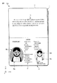
図1に示すラベル付き物品100は、個人認証に使用される冊子体、具体的にはパスポートである。図1には、開いた状態の冊子体を描いている。
FIG. 1 is a plan view schematically showing a labeled article according to an aspect of the present invention.
The labeled
このラベル付き物品100は、折り丁1と表紙2とを含んでいる。なお、X方向及びY方向は、表紙2の主面に平行であり且つ互いに交差する方向である。また、Z方向は、X方向及びY方向に対して垂直な方向である。ここでは、一例として、X方向及びY方向は、互いに直交しているとする。
The labeled
折り丁1は、1枚以上の紙片11からなる。典型的には、紙片11上には、文字列及び地紋などの印刷パターンが設けられている。折り丁1は、1枚の紙片11を又は複数枚の紙片11の束を二つ折りにすることによって形成されている。紙片11は、個人情報が記録されるIC(integrated circuit)チップや、このICチップとの非接触での通信を可能とするアンテナなどを内蔵していてもよい。
The
表紙2は、二つ折りされている。表紙2と折り丁1とは、冊子体を閉じた状態で折り丁1が表紙2によって挟まれるように重ね合わされており、それらの折り目の位置で綴じ合わせなどによって一体化されている。
The
表紙2は、個人情報を含んだ画像を表示する。この個人情報は、個人の認証に利用する個人認証情報を含んでいる。この個人情報は、例えば、生体情報と非生体個人情報とに分類することができる。
The
生体情報は、生体の特徴のうち、その個体に特有なものである。典型的には、生体情報は、光学的手法によって識別可能な特徴である。例えば、生体情報は、顔、指紋、静脈及び虹彩の少なくとも1つの画像又はパターンである。 The biological information is unique to the individual among the characteristics of the biological body. Typically, biometric information is a feature that can be identified by optical techniques. For example, the biometric information is at least one image or pattern of a face, fingerprint, vein, and iris.
非生体個人情報は、生体情報以外の個人情報である。例えば、非生体個人情報は、氏名、生年月日、年齢、血液型、性別、国籍、住所、本籍地、電話番号、所属及び身分の少なくとも1つである。非生体個人情報は、タイプ打ちによって入力された文字を含んでいてもよく、署名などの手書きを機械読み取りすることによって入力された文字を含んでいてもよく、それらの双方を含んでいてもよい。 Non-biological personal information is personal information other than biological information. For example, the non-biological personal information is at least one of name, date of birth, age, blood type, gender, nationality, address, permanent address, telephone number, affiliation, and status. The non-biological personal information may include characters input by typing, may include characters input by machine reading a handwriting such as a signature, or may include both of them. .
図1において、表紙2は、画像I1a、I1b、I2、I3c及びI3dを表示している。
画像I1a及びI2は、物体色の画像である。ここで、「物体色」は、光の吸収及び反射を利用して表示される色である。具体的には、或る物体が表示する「物体色」は、その物体を構成している材料の光学的性質、例えば反射スペクトル又は透過スペクトルに対応した色である。
In FIG. 1, the
The images I1a and I2 are object color images. Here, the “object color” is a color displayed using light absorption and reflection. Specifically, an “object color” displayed by an object is a color corresponding to an optical property of a material constituting the object, for example, a reflection spectrum or a transmission spectrum.
画像I1a及びI2は、白色光で照明し、肉眼で観察した場合に視認可能である。画像I1a及びI2の一方は省略してもよい。 The images I1a and I2 are visible when illuminated with white light and observed with the naked eye. One of the images I1a and I2 may be omitted.
画像I1a及びI2は、例えば、染料及び顔料の少なくとも一方、又は、染料及び顔料の少なくとも一方と透明樹脂との混合物で構成することができる。この場合、画像I1a及びI2の形成には、サーマルヘッドを用いた熱転写記録法、インクジェット記録法、電子写真法、又はそれらの2つ以上の組み合わせを利用することができる。或いは、画像I1a及びI2は、感熱発色剤を含んだ層を形成し、この層にレーザビームで描画することにより形成することができる。或いは、これら方法の組み合わせを利用することができる。画像I2の少なくとも一部は、ホットスタンプを用いた熱転写記録法によって形成してもよく、印刷法によって形成してもよく、それらの組み合わせを利用して形成してもよい。 The images I1a and I2 can be composed of, for example, at least one of a dye and a pigment, or a mixture of at least one of a dye and a pigment and a transparent resin. In this case, the images I1a and I2 can be formed by a thermal transfer recording method using a thermal head, an ink jet recording method, an electrophotographic method, or a combination of two or more thereof. Alternatively, the images I1a and I2 can be formed by forming a layer containing a heat-sensitive color former and drawing on this layer with a laser beam. Alternatively, a combination of these methods can be used. At least a part of the image I2 may be formed by a thermal transfer recording method using a hot stamp, a printing method, or a combination thereof.
画像I1bは、構造色の画像である。ここで、「構造色」は、光の屈折、回折、干渉、反射、又はそれらの2つ以上の組み合わせを利用して表示される色である。具体的には、或る物体が表示する「構造色」は、その物体を構成している材料の光学的性質、例えば屈折率スペクトル及び吸収スペクトルに加え、その物体の構造、例えば、表面若しくは界面の形状並びに層の厚さ及び数に応じて変化する色である。「構造色」を表示する物体を構成している材料は、典型的には、透明材料であるか、金属光沢を有し得る材料であるか、又はそれらの組み合わせである。 The image I1b is a structural color image. Here, the “structural color” is a color displayed using light refraction, diffraction, interference, reflection, or a combination of two or more thereof. Specifically, the “structural color” that an object displays is the optical properties of the material that makes up the object, such as the refractive index spectrum and the absorption spectrum, as well as the structure of the object, such as the surface or interface. The color changes depending on the shape and the thickness and number of layers. The material constituting the object that displays the “structural color” is typically a transparent material, a material that can have a metallic luster, or a combination thereof.
「構造色」は、例えば、ホログラム、回折格子、光散乱構造、又はそれらの2つ以上の組み合わせによって表示することができる。また、複数の凹部及び/又は凸部を不規則に又は規則的に配置してなる構造は、凹部及び凸部の幅又は径に対する深さ又は高さの比が十分に大きく、且つ、凹部及び/又は凸部のピッチが十分に小さい場合には、入射光を閉じ込める効果を有し得る。即ち、低反射率を達成し得る。「構造色」は、このような構造、又は、このような構造とホログラム、回折格子及び光散乱構造の1つ以上との組み合わせによって表示してもよい。ここでは、一例として、画像I1bは、回折格子が表示する画像であるとする。画像I1bは、後で詳述するように、例えば、サーマルヘッドを用いた熱転写記録法によって形成する。 The “structural color” can be displayed by, for example, a hologram, a diffraction grating, a light scattering structure, or a combination of two or more thereof. Further, the structure formed by irregularly or regularly arranging a plurality of concave portions and / or convex portions has a sufficiently large ratio of depth or height to the width or diameter of the concave portions and convex portions, and When the pitch of the convex portions is sufficiently small, it can have an effect of confining incident light. That is, a low reflectance can be achieved. The “structural color” may be displayed by such a structure or a combination of such a structure and one or more of a hologram, a diffraction grating and a light scattering structure. Here, as an example, it is assumed that the image I1b is an image displayed by the diffraction grating. As will be described in detail later, the image I1b is formed by, for example, a thermal transfer recording method using a thermal head.
画像I1a及びI1bは、同一人物の顔画像を含んでいる。画像I1aが含んでいる顔画像と、画像I1bが含んでいる顔画像とは、同一であってもよく、異なっていてもよい。画像I1aが含んでいる顔画像と、画像I1bが含んでいる顔画像とは、寸法が等しくてもよく、異なっていてもよい。また、画像I1a及びI1bの各々は、顔画像の代わりに他の生体情報を含んでいてもよく、顔画像に加えて顔画像以外の生体情報を更に含んでいてもよい。 The images I1a and I1b include face images of the same person. The face image included in the image I1a and the face image included in the image I1b may be the same or different. The face image included in the image I1a and the face image included in the image I1b may have the same or different dimensions. Each of the images I1a and I1b may include other biological information instead of the face image, and may further include biological information other than the face image in addition to the face image.
画像11bは、生体情報の代わりに非生体個人情報を含んでいてもよく、生体情報に加えて非生体個人情報を更に含んでいてもよい。また、画像11bは、個人情報に加えて非個人情報を更に含んでいてもよい。
The
画像I2は、非生体個人情報と非個人情報とを含んでいる。画像I2は、例えば、文字、記号、符号及び標章の1つ以上を構成している。 The image I2 includes non-biological personal information and non-personal information. The image I2 forms, for example, one or more of characters, symbols, codes, and marks.
画像I3cの少なくとも一部は、画像I1aの背景を構成している。画像I3cは、例えば、物体色の画像であるか、又は、構造色の画像である。ここでは、一例として、画像I3cは、構造色の画像であるとする。 At least a part of the image I3c constitutes the background of the image I1a. The image I3c is, for example, an object color image or a structural color image. Here, as an example, it is assumed that the image I3c is a structural color image.
画像I3dの少なくとも一部は、画像I1bの背景を構成している。画像I3dは、例えば、物体色の画像であるか、又は、構造色の画像である。ここでは、一例として、画像I3dは、物体色の画像であるとする。 At least a part of the image I3d constitutes the background of the image I1b. The image I3d is, for example, an object color image or a structural color image. Here, as an example, it is assumed that the image I3d is an object color image.
次に、表紙2の構造について、図2乃至図6を参照しながら説明する。
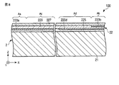
図2は、図1に示すラベル付き物品に採用可能な構造の一例を概略的に示す断面図である。図3は、図1に示すラベル付き物品の一部を拡大して示す平面図である。図4は、図1に示すラベル付き物品の他の部分を拡大して示す平面図である。図5は、図1に示すラベル付き物品の一部を拡大して示す断面図である。図6は、図1に示すラベル付き物品の他の部分を拡大して示す断面図である。
Next, the structure of the
FIG. 2 is a cross-sectional view schematically showing an example of a structure that can be employed in the labeled article shown in FIG. FIG. 3 is an enlarged plan view showing a part of the labeled article shown in FIG. 4 is an enlarged plan view showing another portion of the labeled article shown in FIG. FIG. 5 is an enlarged cross-sectional view of a part of the labeled article shown in FIG. 6 is an enlarged cross-sectional view of another portion of the labeled article shown in FIG.
なお、図3には、表紙2のうち画像I1a及びI3cに対応した部分の構造を描いている。また、図4には、表紙2のうち画像I1b及びI3dに対応した部分の構造を描いている。そして、図5及び図6は、それぞれ、表紙2のうち画像I1bを表示する部分が含んでいる構造と、表紙2のうち画像I3cを表示する部分が含んでいる構造とを描いている。
In FIG. 3, the structure of the portion of the
表紙2は、図2に示すように、表紙本体21と画像表示体22とを含んでいる。
表紙本体21は、ラベル付き物品100の基材であって、典型的には紙片である。表紙本体21は、単層構造を有していてもよく、多層構造を有していてもよい。表紙本体21は、ラベル付き物品100を閉じた状態において、折り丁1を挟み込むように二つ折りされている。
As shown in FIG. 2, the
The cover
画像表示体22は、多層構造を有している層である。画像表示体22は、ラベル付き物品100を閉じた状態において折り丁1と向き合う表紙本体21の主面に貼り付けられている。
The
画像表示体22は、画像表示部220a乃至220dを含んでいる。画像表示部220a乃至220dは、図1に示す画像I1a、I1b、I3c及びI3dを表示する。画像表示体22は、図1に示す画像I2を表示する画像表示部(図示せず)を更に含むことができる。
The
画像表示部220aは、図2に示すように、領域Aaに設けられている。画像表示部220aは、或る対象に関する情報を物体色の画像として表示する。ここでは、画像表示部220aは、図1に示す画像I1aを表示する。
The
画像表示部220aは、例えば、染料及び顔料の少なくとも一方と任意の樹脂とを含んだ層である。画像表示部220aは、例えば、サーマルヘッドを用いた熱転写記録法、インクジェット記録法、電子写真法、又はそれらの2つ以上の組み合わせを利用することにより得ることができる。この場合、画像表示部220aは、例えば、図3に示すように二次元的に配列した複数のドットからなる。
The
画像表示部220bは、図2に示すように、領域Aaと隣り合った領域Abに設けられている。画像表示部220bは、先の対象に関する情報をレリーフ構造に由来する構造色の画像として表示する。ここでは、画像表示部220bは、図1に示す画像I1bを表示する。
As shown in FIG. 2, the
画像表示部220bは、例えば、図5に示すように回折構造形成層223bと反射層224bと接着層225bとを含んだ層である。反射層224bは、回折構造形成層223bと接着層225bとの間に介在している。画像表示部220bは、例えば、回折構造形成層223bと反射層224bとが接着層225bと表紙本体21との間に介在するように設けられる。
The
回折構造形成層223bは、一方の主面にレリーフ型の回折格子が設けられた透明層である。回折構造形成層223bは、例えば、特定の照明方向から白色光で照明して、特定の観察方向から観察した場合に異なる色を表示する第1乃至第3部分を含んでいる。第1乃至第3部分は、回折格子の格子定数及び溝の長さ方向の少なくとも一方が互いに異なっている。特定の観察条件のもとで、第1乃至第3部分は、例えば、青、緑及び赤色を表示する。
The diffraction
回折構造形成層223bの材料としては、例えば、ポリウレタン樹脂、ポリカーボネート樹脂、ポリスチレン樹脂及びポリ塩化ビニル樹脂などの熱可塑性樹脂、不飽和ポリエステル樹脂、メラミン樹脂、エポキシ樹脂、ウレタンアクリレート、ウレタンメタクリレート、ポリオールアクリレート、ポリオールメタクリレート、メラミンアクリレート、メラミンメタクリレート、トリアジンアクリレート及びトリアジンメタアクリレートなどの熱硬化性樹脂、これらの混合物、又はラジカル重合性不飽和基を有する熱成形性材料を使用することができる。回折構造形成層223bは、光硬化性を有している樹脂を使用して形成してもよい。なお、このような透明樹脂を用いて得られる回折構造形成層223bは、典型的には、波長が550nmの光に対する屈折率が1.3乃至1.7の範囲内にある。
Examples of the material of the diffraction
反射層224bは、回折構造形成層223b上に形成されている。反射層224bは、回折構造形成層223bのレリーフ構造が設けられた面の少なくとも一部を被覆している。反射層224bは省略することができるが、反射層224bを設けると、回折構造が表示する画像の視認性が向上する。
The
反射層224bとしては、例えば、透明反射層又は不透明な反射層を使用することができる。そのような反射層224bは、例えば、真空蒸着やスパッタリングなどの真空成膜法によって形成することができる。反射層224bが樹脂を含んでいる場合、反射層224bは、塗布又は印刷を利用して形成してもよい。
As the
反射層224bとして透明反射層を使用すると、反射層224bの背面側に絵柄及び文字等のパターンを配置した場合であっても、これを画像表示体22の前面側から視認することができる。
When a transparent reflective layer is used as the
透明反射層は、単層構造を有していてもよく、多層構造を有していてもよい。後者の場合、透明反射層は、繰り返し反射干渉を生じるように設計されていてもよい。透明反射層の材料としては、例えば、硫化亜鉛及び二酸化チタンなどの透明誘電体を使用することができる。 The transparent reflective layer may have a single layer structure or a multilayer structure. In the latter case, the transparent reflective layer may be designed so as to repeatedly cause reflection interference. As a material of the transparent reflective layer, for example, a transparent dielectric such as zinc sulfide and titanium dioxide can be used.
透明誘電体からなる単層構造の透明反射層は、典型的には、回折構造形成層223bと比較して、上述した波長の光に対する屈折率がより大きい。それらの屈折率の差は、例えば0.2以上である。透明反射層に単層構造を採用した場合、その厚さは例えば10nm乃至1000nmの範囲内とする。
A transparent reflective layer having a single-layer structure made of a transparent dielectric typically has a higher refractive index with respect to light having the above-described wavelength than the diffractive
透明誘電体からなる多層構造の透明反射層は、典型的には、その回折構造形成層223bに最も近い層の上述した波長の光に対する屈折率が、回折構造形成層223bのこの波長の光に対する屈折率と比較してより大きい。それらの屈折率の差は、例えば0.2以上である。
A transparent reflective layer having a multilayer structure made of a transparent dielectric typically has a refractive index with respect to light of the above-mentioned wavelength of the layer closest to the diffraction
或いは、透明反射層として金属層を使用してもよい。金属層の材料としては、例えば、アルミニウム、錫、銅、銀、金及び鉄などの単体金属又はそれらの合金を使用することができる。金属層は、厚い場合には遮光性であるが、薄くすると透明になる。例えば、厚さが20乃至40nmの範囲内にあるアルミニウム層の場合、或る観察条件のもとでは金属光沢を観察できるが、観察角度を変更するとその背景が透けて見える。 Alternatively, a metal layer may be used as the transparent reflective layer. As a material of the metal layer, for example, a single metal such as aluminum, tin, copper, silver, gold, and iron, or an alloy thereof can be used. The metal layer is light-shielding when it is thick, but becomes transparent when it is thin. For example, in the case of an aluminum layer having a thickness in the range of 20 to 40 nm, the metallic luster can be observed under certain observation conditions, but the background can be seen through when the observation angle is changed.
透明反射層として、より厚い金属層を使用することも可能である。例えば、比較的厚い金属層を形成し、これに肉眼での識別が困難な径又は幅の開口を多数設ける。例えば、この金属層を、網点又は万線状にパターニングする。これにより、金属材料からなる透明反射層を得ることができる。 A thicker metal layer can also be used as the transparent reflective layer. For example, a relatively thick metal layer is formed, and a large number of openings having a diameter or width that are difficult to identify with the naked eye are provided. For example, this metal layer is patterned into a halftone dot or a line. Thereby, a transparent reflective layer made of a metal material can be obtained.
不透明な金属反射層の材料としては、例えば、透明反射層としての金属層に関して上述した材料を使用することができる。不透明な金属反射層は、典型的には、肉眼での識別が困難な径又は幅の開口は設けられておらず、光を遮るのに十分な厚さを有している。 As the material of the opaque metal reflection layer, for example, the materials described above with respect to the metal layer as the transparent reflection layer can be used. The opaque metallic reflective layer is typically not provided with an opening having a diameter or width that is difficult to identify with the naked eye, and has a sufficient thickness to block light.
透明反射層又は不透明な反射層として、透明樹脂とこの中で分散した粒子とを含んだ層を使用してもよい。この粒子としては、例えば、単体金属及び合金などの金属材料からなる粒子、又は、透明金属酸化物及び透明樹脂などの透明誘電体からなる粒子を使用することができる。透明樹脂中には、粒子を分散させる代わりに、薄片を分散させてもよい。 A layer containing a transparent resin and particles dispersed therein may be used as the transparent reflective layer or the opaque reflective layer. As the particles, for example, particles made of a metal material such as a single metal and an alloy, or particles made of a transparent dielectric such as a transparent metal oxide and a transparent resin can be used. In the transparent resin, flakes may be dispersed instead of dispersing the particles.
接着層225bは、反射層224b上に設けられている。接着層225bは、例えば熱可塑性樹脂からなる。
The
接着層225bの材料としては、例えば、ウレタン樹脂、ブチラール樹脂、ポリエステル樹脂、ポリ塩化ビニル及び塩化ビニル−酢酸ビニル共重合体などの塩化ビニル系樹脂、ポリウレタン樹脂、エポキシ樹脂、塩素化ポリプロピレン、アクリル樹脂、ポリスチレン、ポリビニルベンゼン、スチレン−ブタジエン共重合樹脂、スチレンとメタクリル酸アルキル(但し、アルキル基の炭素数は2乃至6)とから得られるポリビニル樹脂などのビニル樹脂、ゴム系材料、又は、これらの2種以上を含んだ混合物を使用することができる。
Examples of the material of the
接着層225bには、ワックス、ステアリン酸などの高級脂肪酸、その金属塩及びエステル、可塑剤、ポリテトラフルオロエチレン、ポリエチレン、シリコーン樹脂及びポリアクリロニトリルなどの有機材料からなる有機フィラー、並びにシリカからなどの無機材料からなる無機フィラーの1つ以上を添加してもよい。
For the
接着層225bは、画像表示体22の構成要素であってもよく、画像表示体22の構成要素でなくてもよい。また、このラベル付き物品1において、接着層225bは省略することができる。
The
画像表示部220bは、例えば、サーマルヘッドを用いた熱転写記録法により得ることができる。この場合、画像表示部220bは、例えば、図4に示すように二次元的に配列した複数のドットからなる。
The
画像表示部220cは、図2に示すように、領域Aa及びAbと隣り合い且つ領域Aaと隣接した領域Acに設けられている。画像表示部220cは、画像表示部220aに対応した位置で、画像表示部220aに対応した形状に開口している。画像表示部220cは、画像表示部220aが表示する画像の背景を構造色の画像、例えばレリーフ構造に由来した構造色の画像として表示する。ここでは、画像表示部220cは、図1に示す画像I3cを表示する。
As shown in FIG. 2, the
画像表示部220cは、例えば、図6に示すように回折構造形成層223cと反射層224cと接着層225cとを含んだ層である。反射層224cは、回折構造形成層223cと接着層225cとの間に介在している。画像表示部220cは、例えば、回折構造形成層223cと反射層224cとが接着層225cと表紙本体21との間に介在するように設けられる。
The
回折構造形成層223cは、一方の主面にレリーフ型の回折格子が設けられた透明層である。回折構造形成層223cは、例えば、特定の照明方向から白色光で照明して、特定の観察方向から観察した場合に異なる色を表示する第1乃至第3部分を含んでいる。第1乃至第3部分は、回折格子の格子定数及び溝の長さ方向の少なくとも一方が互いに異なっている。特定の観察条件のもとで、第1乃至第3部分は、例えば、青、緑及び赤色を表示する。
The diffraction
回折構造形成層223cの材料としては、例えば、回折構造形成層223bについて上述したものを使用することができる。なお、このような透明樹脂を用いて得られる回折構造形成層223cは、典型的には、波長が550nmの光に対する屈折率が1.3乃至1.7の範囲内にある。
As the material of the diffraction
反射層224cは、回折構造形成層223c上に形成されている。反射層224cは、回折構造形成層223cのレリーフ構造が設けられた面の少なくとも一部を被覆している。反射層224cは省略することができるが、反射層224cを設けると、回折構造が表示する画像の視認性が向上する。
The
反射層224cとしては、例えば、反射層224bについて上述したものを使用することができる。また、反射層224cは、例えば、反射層224bについて上述した方法により形成することができる。
As the
接着層225cは、反射層224c上に設けられている。接着層225cは、例えば熱可塑性樹脂からなる。接着層225cの材料としては、例えば、接着層225bについて上述したものを使用することができる。
The
画像表示部220cは、例えば、サーマルヘッドを用いた熱転写記録法により得ることができる。この場合、画像表示部220cは、例えば、図3に示すように二次元的に配列した複数のドットからなる。
The
画像表示部220dは、図2に示すように、領域Abと、領域Aa乃至Acと隣り合い且つ領域Abと隣接した領域Adとに設けられている。画像表示部220dの一部は、画像表示部220bと表紙本体21との間に介在している。画像表示部220dは、領域Adにおいて、画像表示部220bが表示する画像の背景、例えば微細な模様を、物体色の画像として表示する。ここでは、画像表示部220dは、図1に示す画像I3dを表示する。また、画像表示部220dは、領域Abにおいて、例えば、画像表示部220bが表示するのと同様の画像を表示する。或いは、画像表示部220dは、領域Abにおいて、画像表示部220bが表示するのとは異なる画像、例えば微細な模様を表示する。
As shown in FIG. 2, the
画像表示部220dは、例えば、染料及び顔料の少なくとも一方と任意の樹脂とを含んだ層である。画像表示部220dは、例えば、サーマルヘッドを用いた熱転写記録法、インクジェット記録法、電子写真法、又はそれらの2つ以上の組み合わせを利用することにより得ることができる。この場合、画像表示部220dは、例えば、図4に示すように二次元的に配列した複数のドットからなる。
The
画像表示部220a乃至220dの厚さは、例えば0.1μm乃至2.0μmの範囲内とする。画像表示部220a乃至220dは、厚さが互いに等しくてもよく、異なっていてもよい。また、画像表示部220a乃至220dの各々は、均一な厚さを有していてもよく、不均一な厚さを有していてもよい。
The thickness of the
画像表示部220a乃至220dの各々について、隣り合ったドットは、互いから離間していてもよく、互いに接していてもよい。後者の場合、隣り合ったドットは部分的に重なり合っていてもよい。この場合、図3及び図4に示すように複数のドットによって囲まれた隙間が存在していてもよく、そのような隙間は存在していなくてもよい。
In each of the
画像表示体22は、図2に示すように、画像表示部220a乃至220dに加え、中間層229と保護層227と接着層225とを更に含んでいる。
As shown in FIG. 2, the
中間層229は、第1及び第2主面を有している。ここでは、第1主面は前面であり、第2主面は、表紙本体21と向き合った背面である。画像形成層220b及び220cは中間層229の前面側に位置している。他方、画像形成層220a及び220dは、中間層229の背面側に位置している。
The
中間層229は、光透過性を有している。例えば、中間層229は、全体が透明であるか又は一部が透明な層である。
The
中間層229は、例えば、透明樹脂からなる。中間層229の材料としては、例えば、熱可塑性ポリアクリル酸エステル樹脂、塩化ゴム系樹脂、塩化ビニル−酢酸ビニル共重合樹脂、セルロース系樹脂、塩素化ポリプロピレン系樹脂、エポキシ樹脂、ポリエステル樹脂、ニトロセルロース系樹脂、スリレンアクリレート系樹脂、ポリエーテル系樹脂、及びポリカーボネート系樹脂等の樹脂を単独又は複合して使用することができる。中間層229は、単層構造を有していてもよく、多層構造を有していてもよい。
The
中間層229の厚さは、例えば、1μm乃至20μmの範囲内とする。中間層229が薄い場合、情報を改竄するべく中間層229が部分的に除去されたとしても、画像表示体22を肉眼で観察することによってそのことを判別できない可能性がある。他方、中間層229が厚い場合、先の除去部に市販のフィルムを設けると、中間層229が市販のフィルムによって部分的に置き換えられたことを、画像表示体22を肉眼で観察することによって判別できない可能性がある。
The thickness of the
中間層229は、面内で均一な光学的性質を有していてもよい。或いは、中間層229は、面内で不均一な光学的性質を有していてもよい。
The
また、中間層229は、ホログラム、回折格子、赤外線吸収層、蛍光層、及び物体色を表示する印刷パターンからなる群より選択される1つ以上を含んでいてもよい。このような中間層229は、部分的に除去された場合に、そのことを容易に判別することができる。なお、赤外線吸収層及び蛍光層は、連続膜であってもよく、格子状、島状又はストライプ状にパターニングされていてもよい。後者の場合、中間層229には、例えば、パターニングされた赤外線吸収層又は蛍光層とこれを支持した光透過層とを含んだ多層構造を採用する。ここでは、一例として、中間層229には、その全体に亘ってレリーフ型のホログラムが設けられていることとする。
The
保護層227は、中間層229の前面を被覆している。保護層227と中間層229とは、画像表示部220b及び220cを間に挟んでいる。
The
保護層227は、光透過性を有しており、典型的には透明である。保護層227は、画像表示部220a乃至220dなどの損傷を抑制する。保護層227は、省略することができる。
The
保護層227は、例えば、熱可塑性樹脂、熱硬化性樹脂、及び紫外線又は電子硬化樹脂などの樹脂からなる。転写箔を利用して画像表示体22を表紙本体21に貼り付ける場合は、柔軟性及び箔切れ性の観点で熱可塑性樹脂を使用することが好ましい。
The
この熱可塑性樹脂としては、例えば、ポリアクリル酸エステル樹脂、塩化ゴム系樹脂、塩化ビニル−酢酸ビニル共重合樹脂、セルロース系樹脂、塩素化ポリプロピレン系樹脂、エポキシ樹脂、ポリエステル樹脂、ニトロセルロース系樹脂、スリレンアクリレート系樹脂、ポリエーテル系樹脂、ポリカーボネート系樹脂、又はそれらの混合物を使用することができる。箔切れ性や耐摩性を考慮して、この樹脂に、石油系ワックス及び植物系ワックスなどのワックス、ステアリン酸などの高級脂肪酸、その金属塩、エステル及びシリコーンオイルなどの滑材、ポリテトラフルオロエチレン、ポリエチレン、シリコーン樹脂及びポリアクリロニトリルなどの有機材料からなる有機フィラー、並びにシリカからなどの無機材料からなる無機フィラーの1つ以上を添加してもよい。 Examples of this thermoplastic resin include polyacrylate resin, chlorinated rubber resin, vinyl chloride-vinyl acetate copolymer resin, cellulose resin, chlorinated polypropylene resin, epoxy resin, polyester resin, nitrocellulose resin, A thylene acrylate resin, a polyether resin, a polycarbonate resin, or a mixture thereof can be used. In consideration of foil cutting properties and abrasion resistance, this resin includes waxes such as petroleum waxes and plant waxes, higher fatty acids such as stearic acid, metal salts thereof, esters and silicone oils and other lubricants, polytetrafluoroethylene One or more of an organic filler made of an organic material such as polyethylene, silicone resin and polyacrylonitrile, and an inorganic filler made of an inorganic material such as silica may be added.
保護層227の厚さは、例えば、1μm乃至20μmの範囲内とする。保護層227が薄い場合、情報を改竄するべく保護層227が部分的に除去されたとしても、画像表示体22を肉眼で観察することによってそのことを判別できない可能性がある。他方、保護層227が厚い場合、先の除去部に市販のフィルムを設けると、保護層227が市販のフィルムによって部分的に置き換えられたことを、画像表示体22を肉眼で観察することによって判別できない可能性がある。
The thickness of the
保護層227は、面内で均一な光学的性質を有していてもよい。或いは、保護層227は、面内で不均一な光学的性質を有していてもよい。
The
また、保護層227は、ホログラム、回折格子、赤外線吸収層、蛍光層、及び物体色を表示する印刷パターンからなる群より選択される1つ以上を含んでいてもよい。このような保護層227は、部分的に除去された場合に、そのことを容易に判別することができる。なお、赤外線吸収層及び蛍光層は、連続膜であってもよく、格子状、島状又はストライプ状にパターニングされていてもよい。後者の場合、保護層227には、例えば、パターニングされた赤外線吸収層又は蛍光層とこれを支持した光透過層とを含んだ多層構造を採用する。
The
接着層225は、反射層224と表紙本体21との間に介在している。接着層225及び中間層229は、画像表示部220a及び220dを間に挟んでいる。
The
接着層225は、例えば熱可塑性樹脂からなる。接着層225の材料としては、例えば、ウレタン樹脂、ブチラール樹脂、ポリエステル樹脂、ポリ塩化ビニル及び塩化ビニル−酢酸ビニル共重合体などの塩化ビニル系樹脂、ポリウレタン樹脂、エポキシ樹脂、塩素化ポリプロピレン、アクリル樹脂、ポリスチレン、ポリビニルベンゼン、スチレン−ブタジエン共重合樹脂、スチレンとメタクリル酸アルキル(但し、アルキル基の炭素数は2乃至6)とから得られるポリビニル樹脂などのビニル樹脂、ゴム系材料、又は、これらの2種以上を含んだ混合物を使用することができる。
The
接着層225には、ワックス、ステアリン酸などの高級脂肪酸、その金属塩及びエステル、可塑剤、ポリテトラフルオロエチレン、ポリエチレン、シリコーン樹脂及びポリアクリロニトリルなどの有機材料からなる有機フィラー、並びにシリカからなどの無機材料からなる無機フィラーの1つ以上を添加してもよい。
For the
接着層225は、画像表示体22の構成要素であってもよく、画像表示体22の構成要素でなくてもよい。また、接着層225は、省略することができる。
The
この画像表示体22は、画像表示部220aを含んでいる。画像表示部220aは、或る人物の顔画像を物体色の画像として表示する。この物体色の顔画像は、通常の照明条件下で観察することができ、しかも、視認性に優れている。
The
また、この画像表示体22は、画像表示部220aに加え、画像表示部220bを含んでいる。画像表示部220bは、レリーフ型の回折格子に由来する構造色の画像を表示する。レリーフ構造を利用した場合、パール顔料を使用した場合と比較して、精細度がより高い画像の表示が可能である。
Further, the
そして、この画像表示体22では、画像表示部220a及び220bは、同一人物の顔画像を表示する。画像表示部220bは、それ自体の偽像又は改竄が困難である。それ故、真正品としてのラベル付き物品100において、画像表示部220a及び220bが同一人物の顔画像、特には同一の顔画像を表示する場合、例えば、真正品であるか否かが不明のラベル付き物品が表示する2つの顔画像を比較することにより、その物品の真偽を判定することができる。
In the
また、画像表示部220bが表示する画像I1bの色は、照明方向及び観察方向などに応じて変化する。そして、画像表示部220bには、画像I1bとして、単色の平面画像、多色の平面画像、単色の立体画像、多色の立体画像、又はそれらの2つ以上の組み合わせを表示させることが可能である。即ち、この構成を採用すると、複雑な視覚効果を達成することができる。
The color of the image I1b displayed by the
加えて、この画像表示体22では、画像表示部220aに物体色の画像I1aを表示させ、画像表示部220cに構造色の画像I3cを画像I1aの背景として表示させる。また、この画像表示体22では、画像表示部220bに構造色の画像I1bを表示させ、画像表示部220dに物体色の画像I3dを画像I1bの背景として表示させる。このように物体色の画像及び構造色の画像の一方を他方の背景とした場合、物体色の画像を物体色の画像の背景とした場合や、構造色の画像を構造色の画像の背景とした場合と比較して、より特殊な視覚効果を達成することができる。例えば、画像表示部220cに画像I3cとして立体感がある画像を表示させることにより、画像I1a及びI3cの組み合わせに、擬似的な立体画像を表示させることができる。
In addition, the
また、この画像表示体22では、画像表示部220dは、領域Adだけでなく、領域Abにも設けられている。即ち、画像表示部220dの一部は、画像表示部220bと向き合っている。それ故、画像表示部220bが光透過性を有している場合、画像表示部220dが領域Abにおいて表示する画像は、画像表示部220bを介して透けて見える。即ち、この画像表示体22は、領域Abにおいて、物体色の画像と構造色の画像とを同時に表示する。即ち、この構成を採用すると、より複雑な視覚効果を達成することができる。
Further, in the
また、顔画像などの生体情報は、その個体に特有である。それ故、この画像表示体22を他の個体のために不正に使用するには、画像表示部220a及び220bが表示する画像の双方を書き換えなければならない。即ち、画像表示部220a及び220bの各々を少なくとも部分的に除去しなければならない。それ故、この場合、これら画像の少なくとも一方が非生体情報である場合と比較して、画像表示体22の不正使用はより困難である。
In addition, biological information such as a face image is unique to the individual. Therefore, in order to illegally use the
更に、この画像表示体22では、画像表示部220a及び220b間に、中間層229が介在している。この画像表示体22を含んだラベル付き物品100では、画像表示体22は、画像表示部220aが中間層229と表紙本体21との間に介在するように表紙本体21に支持されている。それ故、例えば前面側から又は裏面側から画像表示部220a及び220bの各々を少なくとも部分的に除去するためには、中間層229も少なくとも部分的に除去しなければならない。即ち、この画像表示体22に記録されている顔画像を他の人物の顔画像に書き換えるには、例えば、画像表示体22を表紙本体21から剥離し、画像表示体22の裏面側から画像表示部220aを除去し、次いで、中間層229の一部を除去して画像表示部220bを露出させ、その後、これを除去する必要がある。或いは、画像表示体22の前面側から画像表示部220bを除去し、次いで、中間層229の一部を除去して画像表示部220aを露出させ、その後、これを除去する必要がある。このような加工は、不可能であるか又は極めて困難である。しかも、特には保護層227及び中間層229の少なくとも一方がホログラム、回折格子、赤外線吸収層、蛍光層、及び物体色を表示する印刷パターンからなる群より選択される1つ以上を含んでいる場合、そのような加工が施された画像表示体22は、そのような加工が施されていない画像表示体22から比較的容易に判別することができる。
Further, in this
また、この画像表示体22では、画像表示部220cは、画像表示部220aに対応した位置で及び画像表示部220aに対応した形状に開口しており、画像I1aの背景を構造色の画像I3cとして表示する。この構成を採用すると、画像表示部220aが表示する画像I1aのみを改竄したときに、改竄した画像I1aの輪郭と画像表示部220cに設けた開口とに形状又は位置の不一致を生じ易い。それ故、これを利用して、情報が改竄されたことを確認することができる。
In the
それ故、この画像表示体22は、記録された画像の改竄が困難である。従って、この画像表示体22を含んだラベル付き物品100は、不正使用され難い。
Therefore, it is difficult for the
このラベル付き物品100には、様々な変形が可能である。
図7は、図1に示すラベル付き物品に採用可能な構造の他の例を概略的に示す断面図である。
Various modifications can be made to the labeled
FIG. 7 is a cross-sectional view schematically showing another example of a structure that can be employed in the labeled article shown in FIG.
図7に示すラベル付き物品100は、以下の点を除いて、図1乃至図6を参照しながら説明したラベル付き物品100と同様である。
The labeled
このラベル付き物品100の画像表示体22は、画像表示部220c及び220dを含んでいない。そして、画像表示部220aは、領域Aaだけでなく、領域Acにも設けられている。また、画像表示部220bは、領域Abだけでなく、領域Adにも設けられている。即ち、画像表示部220aは、図1に示す画像I1a及びI3cを物体色の画像として表示する。また、画像表示部220bは、図1に示す画像I1b及びI3dを構造色の画像として表示する。
The
この構成を採用した場合、画像表示部220c及び220dを設けることに伴う効果が得られないことを除き、図1乃至図6を参照しながら説明した構成を採用した場合と同様の効果を得ることができる。
When this configuration is adopted, the same effect as that obtained when the configuration described with reference to FIGS. 1 to 6 is employed can be obtained except that the effect of providing the
なお、ここでは、画像表示部220aを領域Aaだけでなく領域Acにも設けているが、画像表示部220aは領域Acに設けなくてもよい。即ち、図1に示す画像I3cは省略してもよい。また、ここでは、画像表示部220bを領域Abだけでなく領域Adにも設けているが、画像表示部220bは領域Adに設けなくてもよい。即ち、図1に示す画像I3dは省略してもよい。
Although the
図8は、図1に示すラベル付き物品に採用可能な構造の更に他の例を概略的に示す断面図である。 FIG. 8 is a cross-sectional view schematically showing still another example of a structure that can be employed in the labeled article shown in FIG.
図8に示すラベル付き物品100は、以下の点を除いて、図1乃至図6を参照しながら説明したラベル付き物品100と同様である。
The labeled
このラベル付き物品100の画像表示体22は、画像表示部220cを含んでいない。そして、画像表示部220aは、領域Aaだけでなく、領域Acにも設けられている。即ち、画像表示部220aは、図1に示す画像I1a及びI3cを物体色の画像として表示する。
The
この構成を採用した場合、画像表示部220cを設けることに伴う効果が得られないことを除き、図1乃至図6を参照しながら説明した構成を採用した場合と同様の効果を得ることができる。
When this configuration is employed, the same effect as that obtained when the configuration described with reference to FIGS. 1 to 6 is employed can be obtained except that the effect associated with the provision of the
図9は、図1に示すラベル付き物品に採用可能な構造の更に他の例を概略的に示す断面図である。 FIG. 9 is a cross-sectional view schematically showing still another example of a structure that can be employed in the labeled article shown in FIG.
図9に示すラベル付き物品100は、以下の点を除いて、図1乃至図6を参照しながら説明したラベル付き物品100と同様である。
The labeled
このラベル付き物品100の画像表示体22は、画像表示部220cを含んでいない。そして、画像表示部220aは、領域Aaだけでなく、領域Acにも設けられている。即ち、画像表示部220aは、図1に示す画像I1a及びI3cを物体色の画像として表示する。また、図9に示すラベル付き物品の画像表示体22は、物体色を表示する画像表示部220dの代わりに、光源色を表示する画像表示部220d’を含んでいる。画像表示部220d’は、例えば、蛍光体からなるか、又は、蛍光体と透明樹脂とを含んだ混合物からなる。
The
この構成を採用した場合、画像表示部220cを設けることに伴う効果は得られない。また、画像表示部220d’が無色透明である場合には、画像表示部220dを設けることに伴う効果も得られない。但し、画像表示部220d’は、紫外光などの励起光を照射したときに光源色の画像を表示する。そして、画像表示部220d’が例えば無色透明である場合には、画像表示部220d’を潜像として利用することができる。
When this configuration is adopted, the effect associated with providing the
即ち、画像表示部220d’が無色透明である場合、画像表示部220c及び220dを設けることに伴う効果は得られないことを除き、図1乃至図6を参照しながら説明した構成を採用した場合と同様の効果を得ることができる。加えて、この場合、画像表示部220d’を利用して、励起光を照射することによって可視化する潜像を記録することができる。それ故、このラベル付き物品100を真正品とした場合、真正品であるか否かが不明のラベル付き物品を励起光で照明して、この物品が表示する画像を観察することにより、その物品が真正品であるか否かを判別することができる。
That is, when the
また、画像表示部220d’が有色透明であるか、無色不透明であるか、又は有色不透明である場合、画像表示部220cを設けることに伴う効果は得られないことを除き、図1乃至図6を参照しながら説明した構成を採用した場合と同様の効果を得ることができる。加えて、この場合、画像表示部220d’は、自然光で照明した場合と励起光で照明した場合とで異なる色を表示する。即ち、複雑な視覚効果を提供する。
Further, when the
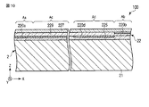
図10は、図1に示すラベル付き物品に採用可能な構造の更に他の例を概略的に示す断面図である。 FIG. 10 is a cross-sectional view schematically showing still another example of a structure that can be employed in the labeled article shown in FIG.
図10に示すラベル付き物品100は、以下の点を除いて、図1乃至図6を参照しながら説明したラベル付き物品100と同様である。
The labeled
このラベル付き物品100の画像表示体22は、画像表示部220cを含んでいない。画像表示部220aは、領域Aaだけでなく、領域Acにも設けられている。即ち、画像表示部220aは、図1に示す画像I1a及びI3cを物体色の画像として表示する。また、画像表示部220dは、領域Abには設けられておらず、領域Adにのみ設けられている。
The
この構成を採用した場合、以下の事項を除き、図1乃至図6を参照しながら説明した構成を採用した場合と同様の効果を得ることができる。即ち、この構成を採用した場合、画像表示部220cを設けることに伴う効果は得られない。また、画像表示部220bが光透過性を有していたとしても、画像表示部220bを介して画像表示部220dが透けて見えることはない。但し、この構成を採用した場合、画像表示部220bが表示する画像I1bを改竄したときに、改竄した画像I1bの輪郭と画像表示部220dに設けた開口とに形状又は位置の不一致を生じ易い。それ故、これを利用して、情報が改竄されたことを確認することができる。
When this configuration is adopted, the same effects as when the configuration described with reference to FIGS. 1 to 6 is adopted can be obtained except for the following matters. That is, when this configuration is adopted, the effect associated with providing the
図11は、図1に示すラベル付き物品に採用可能な構造の更に他の例を概略的に示す断面図である。 FIG. 11 is a cross-sectional view schematically showing still another example of a structure that can be employed in the labeled article shown in FIG.
図11に示すラベル付き物品100は、以下の点を除いて、図1乃至図6を参照しながら説明したラベル付き物品100と同様である。
The labeled
このラベル付き物品100の画像表示体22は、画像表示部220dを含んでいない。そして、画像表示部220bは、領域Abだけでなく、領域Adにも設けられている。即ち、画像表示部220bは、図1に示す画像I1b及びI3dを構造色の画像として表示する。また、画像表示部220cは、領域Acだけでなく、領域Aaにも設けられている。この画像表示部220cは、少なくとも領域Aaにおいて光透過性を有している。画像表示部220cは、図1に示すように、領域Abにおいて、画像I1aの背景として画像I3cを表示する。そして、画像表示部220cは、領域Aaにおいて、例えば、画像表示部220aが表示するのと同様の画像を表示する。或いは、画像表示部220cは、領域Aaにおいて、画像表示部220aが表示するのとは異なる画像、例えば微細な模様を表示する。
The
この構成を採用した場合、以下の事項を除き、図1乃至図6を参照しながら説明した構成を採用した場合と同様の効果を得ることができる。即ち、この構成を採用した場合、画像表示部220dを設けることに伴う効果は得られない。但し、画像表示部220cの一部は画像表示部220aと向き合っているので、画像表示部220aが領域Aaにおいて表示する画像は、画像表示部220cを介して透けて見える。即ち、この画像表示体22は、領域Aaにおいて、物体色の画像と構造色の画像とを同時に表示する。それ故、この構成を採用すると、より複雑な視覚効果を達成することができる。
When this configuration is adopted, the same effects as when the configuration described with reference to FIGS. 1 to 6 is adopted can be obtained except for the following matters. That is, when this configuration is adopted, the effect associated with providing the
図12は、図1に示すラベル付き物品に採用可能な構造の更に他の例を概略的に示す断面図である。 12 is a cross-sectional view schematically showing still another example of a structure that can be employed in the labeled article shown in FIG.
図12に示すラベル付き物品100は、以下の点を除いて、図1乃至図6を参照しながら説明したラベル付き物品100と同様である。
The labeled
このラベル付き物品100の画像表示体22は、画像表示部220dを含んでいない。そして、画像表示部220bは、領域Abだけでなく、領域Adにも設けられている。即ち、画像表示部220bは、図1に示す画像I1b及びI3dを構造色の画像として表示する。
The
この構成を採用した場合、画像表示部220dを設けることに伴う効果が得られないことを除き、図1乃至図6を参照しながら説明した構成を採用した場合と同様の効果を得ることができる。
When this configuration is employed, the same effect as that obtained when the configuration described with reference to FIGS. 1 to 6 is employed can be obtained except that the effect associated with providing the
以上の構成では、画像表示部220a及び220bをそれぞれ中間層229の背面側及び前面側に配置している。以下に説明するように、画像表示部220a及び220bは、それぞれ、中間層229の前面側及び背面側に配置することも可能である。
In the above configuration, the
図13は、図1に示すラベル付き物品に採用可能な構造の更に他の例を概略的に示す断面図である。 FIG. 13 is a cross-sectional view schematically showing still another example of a structure that can be employed in the labeled article shown in FIG.
図13に示すラベル付き物品100は、以下の点を除いて、図1乃至図6を参照しながら説明したラベル付き物品100と同様である。
The labeled
このラベル付き物品100の画像表示体22は、画像表示部220c及び220dを含んでいない。画像表示部220aは、中間層229と保護層227との間に介在し、領域Aaだけでなく、領域Acにも設けられている。また、画像表示部220bは、中間層229と接着層225との間に介在し、領域Abだけでなく、領域Adにも設けられている。即ち、画像表示部220aは、図1に示す画像I1a及びI3cを物体色の画像として表示する。また、画像表示部220bは、図1に示す画像I1b及びI3dを構造色の画像として表示する。
The
この構成を採用した場合、画像表示部220c及び220dを設けることに伴う効果が得られないことを除き、図1乃至図6を参照しながら説明した構成を採用した場合と同様の効果を得ることができる。
When this configuration is adopted, the same effect as that obtained when the configuration described with reference to FIGS. 1 to 6 is employed can be obtained except that the effect of providing the
図14は、図1に示すラベル付き物品に採用可能な構造の更に他の例を概略的に示す断面図である。 14 is a cross-sectional view schematically showing still another example of a structure that can be employed in the labeled article shown in FIG.
図14に示すラベル付き物品100は、以下の点を除いて、図1乃至図6を参照しながら説明したラベル付き物品100と同様である。
The labeled
このラベル付き物品100の画像表示体22は、画像表示部220cを含んでいない。画像表示部220aは、中間層229と保護層227との間に介在しており、領域Aaだけでなく、領域Acにも設けられている。即ち、画像表示部220aは、図1に示す画像I1a及びI3cを物体色の画像として表示する。また、この画像表示体22は、画像表示部220dの代わりに、図9を参照しながら説明した画像表示部220d’を含んでいる。画像表示部220d’は、中間層229と保護層227との間に介在している。更に、この画像表示体22では、画像表示部220dは、中間層229と接着層225との間に介在しており、領域Abには設けられておらず、領域Adにのみ設けられている。
The
この構成を採用した場合、画像表示部220c及び220dを設けることに伴う効果は得られない。但し、画像表示部220d’は、紫外光などの励起光を照射したときに光源色の画像を表示する。そして、画像表示部220d’が例えば無色透明である場合には、画像表示部220d’を潜像として利用することができる。
When this configuration is employed, the effects associated with providing the
即ち、画像表示部220d’が無色透明である場合、画像表示部220c及び220dを設けることに伴う効果は得られないことを除き、図1乃至図6を参照しながら説明した構成を採用した場合と同様の効果を得ることができる。加えて、この場合、画像表示部220d’を利用して、励起光を照射することによって可視化する潜像を記録することができる。それ故、このラベル付き物品100を真正品とした場合、真正品であるか否かが不明のラベル付き物品を励起光で照明して、この物品が表示する画像を観察することにより、その物品が真正品であるか否かを判別することができる。
That is, when the
また、画像表示部220d’が有色透明であるか、無色不透明であるか、又は有色不透明である場合、以下の事項を除き、図1乃至図6を参照しながら説明した構成を採用した場合と同様の効果を得ることができる。即ち、この構成を採用した場合、画像表示部220cを設けることに伴う効果は得られない。また、画像表示部220bが光透過性を有していたとしても、画像表示部220bを介して画像表示部220d’が透けて見えることはない。但し、この構成を採用した場合、画像表示部220bが表示する画像I1bを改竄したときに、改竄した画像I1bの輪郭と画像表示部220d’に設けた開口とに形状又は位置の不一致を生じ易い。それ故、これを利用して、情報が改竄されたことを確認することができる。
When the
図15は、図1に示すラベル付き物品に採用可能な構造の更に他の例を概略的に示す断面図である。 FIG. 15 is a cross-sectional view schematically showing still another example of a structure that can be employed in the labeled article shown in FIG.
図15に示すラベル付き物品100は、以下の点を除いて、図1乃至図6を参照しながら説明したラベル付き物品100と同様である。
The labeled
このラベル付き物品100の画像表示体22では、画像表示部220aは中間層229と保護層227との間に介在し、画像表示部220b及び220cは中間層229と接着層225との間に介在している。この画像表示体22は、画像表示部220dを含んでいない。画像表示部220bは、領域Abだけでなく、領域Adにも設けられている。即ち、画像表示部220bは、図1に示す画像I1b及びI3dを構造色の画像として表示する。
In the
この構成を採用した場合、画像表示部220dを設けることに伴う効果が得られないことを除き、図1乃至図6を参照しながら説明した構成を採用した場合と同様の効果を得ることができる。
When this configuration is employed, the same effect as that obtained when the configuration described with reference to FIGS. 1 to 6 is employed can be obtained except that the effect associated with providing the
図16は、図1に示すラベル付き物品に採用可能な構造の更に他の例を概略的に示す断面図である。 FIG. 16 is a cross-sectional view schematically showing still another example of a structure that can be employed in the labeled article shown in FIG.
図16に示すラベル付き物品100は、以下の点を除いて、図1乃至図6を参照しながら説明したラベル付き物品100と同様である。
The labeled
このラベル付き物品100の画像表示体22では、画像表示部220a及び220dは中間層229と保護層227との間に介在し、画像表示部220bは中間層229と接着層225との間に介在している。この画像表示体22は、画像表示部220cを含んでいない。画像表示部220aは、領域Aaだけでなく、領域Acにも設けられている。即ち、画像表示部220aは、図1に示す画像I1a及びI3cを物体色の画像として表示する。また、画像表示部220dは、例えば、少なくとも領域Abにおいて光透過性を有している。或いは、画像表示部220dは、少なくとも領域Abにおいて、例えば、格子状、島状又はストライプ状のパターンを形成している。
In the
この構成を採用した場合、以下の事項を除き、図1乃至図6を参照しながら説明した構成を採用した場合と同様の効果を得ることができる。即ち、この構成を採用した場合、画像表示部220cを設けることに伴う効果は得られない。但し、画像表示部220dの一部は画像表示部220bと向き合っているので、画像表示部220bが領域Abにおいて表示する画像は、画像表示部220dを介して透けて見える。即ち、この画像表示体22は、領域Abにおいて、物体色の画像と構造色の画像とを同時に表示する。それ故、この構成を採用すると、より複雑な視覚効果を達成することができる。
When this configuration is adopted, the same effects as when the configuration described with reference to FIGS. 1 to 6 is adopted can be obtained except for the following matters. That is, when this configuration is adopted, the effect associated with providing the
上述した構成においては、画像表示部220b及び220cの各々はレリーフ型の回折格子を含んでいる。画像表示部220b及び220cの少なくとも一方は、レリーフ型の回折格子の代わりにレリーフ型のホログラムを含んでいてもよい。或いは、画像表示部220b及び220cの少なくとも一方は、レリーフ型の回折格子に加えて、レリーフ型のホログラムを含んでいてもよい。或いは、画像表示部220b及び220cの少なくとも一方は、レリーフ型の回折格子の代わりに又はレリーフ型の回折格子に加えて、以下に説明するレリーフ型の光散乱構造又はこの光散乱構造とレリーフ型ホログラムとの組み合わせを含んでいてもよい。
In the configuration described above, each of the
図17は、光散乱を利用して構造色を表示する画像表示部に採用可能な構造の一例を概略的に示す平面図である。図18は、光散乱を利用して構造色を表示する画像表示部に採用可能な構造の他の例を概略的に示す斜視図である。図19は、光散乱を利用して構造色を表示する画像表示部に採用可能な構造の更に他の例を概略的に示す斜視図である。 FIG. 17 is a plan view schematically illustrating an example of a structure that can be employed in an image display unit that displays structural colors using light scattering. FIG. 18 is a perspective view schematically showing another example of a structure that can be employed in an image display unit that displays structural colors using light scattering. FIG. 19 is a perspective view schematically showing still another example of a structure that can be employed in an image display unit that displays structural colors using light scattering.
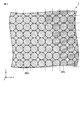
図17に示す構造では、Z方向に対して垂直な界面IFに、複数の凹部及び/又は凸部RPが設けられている。凹部及び/又は凸部RPは、各々がX方向に延びた形状を有しており、Y方向に配列している。凹部及び/又は凸部RPは、X方向に沿った長さが不均一であり、X方向及びY方向における位置も不規則である。 In the structure shown in FIG. 17, a plurality of concave portions and / or convex portions RP are provided at the interface IF perpendicular to the Z direction. Each of the concave portions and / or the convex portions RP has a shape extending in the X direction, and is arranged in the Y direction. The concave portion and / or the convex portion RP have a nonuniform length along the X direction, and the positions in the X direction and the Y direction are also irregular.
この構造は、例えば白色光で照明すると、X方向に垂直な面内において高い光散乱能を示し、Y方向に垂直な面内においては低い光散乱能を示す。従って、この構造は、散乱光の射出方向を制限することが望まれる場合、即ち光散乱異方性が望まれる場合に適している。 For example, when illuminated with white light, this structure exhibits a high light scattering ability in a plane perpendicular to the X direction and a low light scattering ability in a plane perpendicular to the Y direction. Therefore, this structure is suitable when it is desired to limit the emission direction of scattered light, that is, when light scattering anisotropy is desired.
この構造においては、凹部及び/又は凸部RPの配置を変更することにより、光散乱異方性が変化する。例えば、凹部及び/又は凸部RPのY方向における密度を高くすると、光散乱異方性が大きくなる。また、凹部及び/又は凸部RPの長さを短くするか又はそれらの長さ方向の均一性を低下させると、光散乱異方性が小さくなる。 In this structure, the light scattering anisotropy is changed by changing the arrangement of the concave portions and / or the convex portions RP. For example, when the density in the Y direction of the concave portions and / or the convex portions RP is increased, the light scattering anisotropy increases. Further, when the length of the concave portion and / or the convex portion RP is shortened or the uniformity in the length direction thereof is reduced, the light scattering anisotropy is reduced.
なお、図17において、凹部及び/又は凸部RPの長さ方向は、X方向に対して平行である。凹部及び/又は凸部RPの長さ方向は、X方向に対して交差していてもよい。また、図17において、凹部及び/又は凸部RPの長さ方向は、一方向に揃っている。上述した光散乱異方性が得られる限り、凹部及び/又は凸部RPの長さ方向は一方向に揃っていなくてもよい。 In FIG. 17, the length direction of the concave portion and / or the convex portion RP is parallel to the X direction. The length direction of the concave portion and / or the convex portion RP may intersect the X direction. In FIG. 17, the length directions of the concave portion and / or the convex portion RP are aligned in one direction. As long as the above-described light scattering anisotropy is obtained, the length directions of the concave portions and / or the convex portions RP may not be aligned in one direction.
図18に示す構造では、凹部及び/又は凸部RPは、直方体形状を有している。凹部及び/又は凸部RPは、各々がX方向に延びた形状を有しており、Y方向に配列している。凹部及び/又は凸部RPは、X方向及びY方向における位置が不規則であり、X方向及びY方向の寸法も不規則である。このように、光散乱異方性は、凹部及び/又は凸部RPの寸法を変更することによっても変化させることができる。 In the structure shown in FIG. 18, the concave portion and / or the convex portion RP has a rectangular parallelepiped shape. Each of the concave portions and / or the convex portions RP has a shape extending in the X direction, and is arranged in the Y direction. The positions of the recesses and / or the protrusions RP are irregular in the X direction and the Y direction, and the dimensions in the X direction and the Y direction are also irregular. Thus, the light scattering anisotropy can also be changed by changing the size of the concave portion and / or the convex portion RP.
図19に示す構造では、凹部及び/又は凸部RPは、楕円柱形状を有している。凹部及び/又は凸部RPは、各々がX方向に延びた形状を有しており、Y方向に配列している。凹部及び/又は凸部RPは、X方向及びY方向における位置が不規則であり、X方向及びY方向の寸法も不規則である。このように、光散乱異方性は、凹部及び/又は凸部RPの形状を変更することによっても変化させることができる。 In the structure shown in FIG. 19, the concave portion and / or the convex portion RP has an elliptic cylinder shape. Each of the concave portions and / or the convex portions RP has a shape extending in the X direction, and is arranged in the Y direction. The positions of the recesses and / or the protrusions RP are irregular in the X direction and the Y direction, and the dimensions in the X direction and the Y direction are also irregular. Thus, the light scattering anisotropy can also be changed by changing the shape of the concave portion and / or the convex portion RP.
光散乱異方性を有している光散乱構造は、例えば、立体画像の表示に利用可能である。即ち、右眼用のサブ画素と左眼用のサブ画素とからなる画素をマトリクス状に配置する。右眼用のサブ画素の一部には、右眼用の視差画像を表示させるべく、右眼用の光散乱構造を設ける。他方、左眼用のサブ画素の一部には、左眼用の視差画像を表示させるべく、左眼用の光散乱構造を設ける。右眼用の光散乱構造と左眼用の光散乱構造とは、凹部及び/又は凸部RPの長さ方向が異なっている。このような構成を採用すると、屋内において典型的な拡散光照明条件下において、拡散光を利用した立体画像の表示が可能となる。 A light scattering structure having light scattering anisotropy can be used, for example, for displaying a stereoscopic image. That is, pixels composed of right-eye subpixels and left-eye subpixels are arranged in a matrix. A right-eye light scattering structure is provided in a part of the right-eye sub-pixel to display a parallax image for the right eye. On the other hand, a light scattering structure for the left eye is provided in some of the sub-pixels for the left eye in order to display a parallax image for the left eye. The light-scattering structure for the right eye and the light-scattering structure for the left eye are different in the length direction of the concave portion and / or the convex portion RP. By adopting such a configuration, it is possible to display a stereoscopic image using diffused light under typical diffused light illumination conditions indoors.
画像表示部220b及び220cの少なくとも一方は、以下に説明するレリーフ構造を含んでいてもよい。
At least one of the
図20は、構造色として暗色を表示する画像表示部に採用可能な構造の一例を概略的に示す斜視図である。 FIG. 20 is a perspective view schematically showing an example of a structure that can be employed in an image display unit that displays a dark color as a structural color.
図20に示す構造では、界面IFには、二次元的に配列した複数の凹部及び/又は凸部RPが設けられている。この例では、凹部及び/又は凸部RPは、X方向とY方向とに格子状に配列している。凹部及び/又は凸部RPは、斜めに交差する2方向に格子状に配列していてもよい。 In the structure shown in FIG. 20, the interface IF is provided with a plurality of concave portions and / or convex portions RP arranged two-dimensionally. In this example, the concave portions and / or the convex portions RP are arranged in a lattice shape in the X direction and the Y direction. The concave portions and / or the convex portions RP may be arranged in a lattice shape in two directions that intersect diagonally.
凹部及び/又は凸部RPの各々は、先細り形状を有している。先細り形状は、例えば、半紡錘形状、円錐及び角錐などの錐体形状、又は切頭円錐及び切頭角錐などの切頭錐体形状である。凸部PRの側面は、傾斜面のみで構成されていてもよく、階段状であってもよい。先細り形状は、図20に示すレリーフ構造の光反射率を小さくするのに役立つ。凹部及び/又は凸部RPは、先細り形状を有していなくてもよい。 Each of the concave portion and / or the convex portion RP has a tapered shape. The tapered shape is, for example, a semi-spindle shape, a cone shape such as a cone and a pyramid, or a truncated cone shape such as a truncated cone and a truncated pyramid. The side surface of the convex part PR may be composed only of an inclined surface or may be stepped. The tapered shape is useful for reducing the light reflectance of the relief structure shown in FIG. The concave portion and / or the convex portion RP may not have a tapered shape.
凹部及び/又は凸部RPは、回折格子を形成している。但し、凹部及び/又は凸部RPの中心間距離は、通常の回折格子の格子定数と比較して短い。凹部及び/又は凸部RPの中心間距離は、例えば400nm以下である。 The concave portion and / or the convex portion RP forms a diffraction grating. However, the distance between the centers of the recesses and / or the protrusions RP is shorter than the lattice constant of a normal diffraction grating. The distance between the centers of the recesses and / or the protrusions RP is, for example, 400 nm or less.
凹部及び/又は凸部RPの高さ又は深さのそれらの中心間距離に対する比は、例えば1/2倍以上であり、典型的には1倍以上である。この比が大きいほど、レリーフ構造の反射率が小さくなる。 The ratio of the height or depth of the concave portion and / or convex portion RP to their center-to-center distance is, for example, 1/2 times or more, and typically 1 time or more. The greater this ratio, the smaller the reflectance of the relief structure.
このレリーフ構造は、反射率が小さいため、暗灰色乃至黒色に見える。また、このレリーフ構造は、凹部及び/又は凸部RPの中心間距離が小さいため、視感度が高い回折光を正面方向に射出することはなく、限られた角度範囲内にのみ射出する。即ち、このレリーフ構造は、暗灰色乃至黒色印刷層の如く見える。そして、このレリーフ構造は、回折光を射出し得ることを悟られ難い。 This relief structure looks dark gray or black because of its low reflectivity. In addition, since the relief structure has a small distance between the centers of the concave portions and / or the convex portions RP, diffracted light with high visibility is not emitted in the front direction, and is emitted only within a limited angle range. That is, the relief structure looks like a dark gray to black print layer. It is difficult to realize that this relief structure can emit diffracted light.
なお、図20に示す構造では、凹部及び/又は凸部RPは規則的に配置されているが、凹部及び/又は凸部RPは不規則に配置されていてもよい。そのようなレリーフ構造は、回折光を射出しないが、暗灰色乃至黒色印刷層の如く見える。 In addition, in the structure shown in FIG. 20, although the recessed part and / or convex part RP are arrange | positioned regularly, the recessed part and / or convex part RP may be arrange | positioned irregularly. Such a relief structure does not emit diffracted light but looks like a dark gray to black printed layer.
次に、上述したラベル付き物品100の製造方法を説明する。
図21は、図1に示すラベル付き物品の製造に利用可能な製造装置の一例を概略的に示す図である。
Next, the manufacturing method of the labeled
FIG. 21 is a diagram schematically illustrating an example of a manufacturing apparatus that can be used for manufacturing the labeled article illustrated in FIG. 1.
図21に示す製造装置500は、例えば、図2を参照しながら説明した構造を採用したラベル付き物品100の製造に利用可能である。
A
ラベル付き物品100の製造においては、例えば、まず、撮像装置を用いて、人物の顔を撮影する。或いは、印画から顔画像を読み取る。これにより、画像情報を電子情報として得る。この顔画像は、必要に応じて画像処理する。
In manufacturing the labeled
次に、図21に示す製造装置500を用いて、物品100’上に、図2に示す画像表示体22を形成する。なお、物品100’は、画像表示体22を省略したラベル付き物品100、ここでは冊子本体である。
Next, the
図21に示す製造装置500を用いた画像表示体22の形成に際しては、熱転写リボン520ac、520bc、527及び529を準備しておく。
When forming the
熱転写リボン520adは、ロール540bに巻かれている。熱転写リボン520adは、帯状の第1支持体と、その上に形成された第1転写材層とを含んでいる。第1転写材層は、第1支持体によって剥離可能に支持されている。第1転写材層の一部は画像形成層220aとして使用し、第1転写材層の他の一部は画像形成層220dとして使用する。
The thermal transfer ribbon 520ad is wound around a roll 540b. The thermal transfer ribbon 520ad includes a strip-shaped first support and a first transfer material layer formed thereon. The first transfer material layer is detachably supported by the first support. A part of the first transfer material layer is used as the
熱転写リボン520bcは、ロール540dに巻かれている。熱転写リボン520bcは、帯状の第2支持体と、その上に形成された第2転写材層とを含んでいる。第2転写材層は、第2支持体によって剥離可能に支持されている。第2転写材層の一部は画像形成層220bとして使用し、第2転写材層の他の一部は画像形成層220cとして使用する。
The thermal transfer ribbon 520bc is wound around a roll 540d. The thermal transfer ribbon 520bc includes a belt-like second support and a second transfer material layer formed thereon. The second transfer material layer is detachably supported by the second support. A part of the second transfer material layer is used as the
熱転写リボン527は、ロール540cに巻かれている。熱転写リボン527は、帯状の第3支持体と、その上に形成された第3転写材層とを含んでいる。第3転写材層は、第3支持体によって剥離可能に支持されている。第3転写材層の一部は保護層227として使用する。
The
熱転写リボン529は、ロール540aに巻かれている。熱転写リボン529は、帯状の第4支持体と、その上に形成された第4転写材層とを含んでいる。第4転写材層は、第4支持体によって剥離可能に支持されている。第4転写材層の一部は中間層229として使用する。
The
以上の熱転写リボン520ac、520bc、527及び529を準備したうえで、熱転写リボン529及び520adを、それぞれ、ロール540a及び540bから繰り出し、それらの転写材層が向き合うように熱転写印字装置550aへと送る。熱転写印字装置550aにおいては、熱転写リボン520adの第1転写材層の一部を、画像表示部220a及び220dとして、その第1支持体から熱転写リボン529の第4転写材層上へと熱転写する。
After preparing the thermal transfer ribbons 520ac, 520bc, 527 and 529, the
この熱転写に使用した熱転写リボン520adは、ロール570aに巻き取る。他方、画像表示部220a及び220dを形成した熱転写リボン529は、ガイドローラ580aによって案内して、物品100’とともに熱転写装置560aへと送る。
The thermal transfer ribbon 520ad used for this thermal transfer is wound around a
熱転写装置560aにおいては、熱転写リボン529の第4転写材層の一部を、画像表示部220a及び220dとともに、その第4支持体から物品100’の表紙本体12上へと熱転写する。これにより、表紙本体21上に、画像表示部220a及び220d並びに中間層229を形成する。
In the
なお、この熱転写は、熱転写リボン529と表紙本体12との間に接着層225を介在させて行ってもよい。例えば、熱転写リボン529及び表紙本体21の少なくとも一方の上に接着層225を形成しておき、その後、熱転写を行ってもよい。
The thermal transfer may be performed with an
この熱転写に使用した熱転写リボン529は、ガイドローラ580b及び580cによって案内して、巻取りロール570aに巻き取る。他方、この熱転写を終えた物品100’は、熱転写装置560bへと送る。
The
以上の操作と並行して、熱転写リボン527及び520bcを、それぞれ、ロール540c及び540dから繰り出し、それらの転写材層が向き合うように熱転写印字装置550bへと送る。熱転写印字装置550bにおいては、熱転写リボン520bcの第2転写材層の一部を、画像表示部220b及び220cとして、その第2支持体から熱転写リボン527の第3転写材層上へと熱転写する。
In parallel with the above operation, the
この熱転写に使用した熱転写リボン520bcは、ロール570cに巻き取る。他方、画像表示部220b及び220cを形成した熱転写リボン527は、ガイドローラ580dによって案内して、熱転写装置560から送り出した物品100’とともに熱転写装置560bへと送る。
The thermal transfer ribbon 520bc used for this thermal transfer is wound up on a roll 570c. On the other hand, the
熱転写装置560bにおいては、熱転写リボン527の第3転写材層の一部を、画像表示部220b及び220cとともに、その第3支持体から物品100’の表紙本体12上に設けられた中間層229上へと熱転写する。これにより、中間層229上に、画像表示部220b及び220c並びに保護層227を形成する。
In the
なお、この熱転写は、熱転写リボン527と中間層229との間に接着層を介在させて行ってもよい。例えば、熱転写リボン527及び中間層229の少なくとも一方の上に接着層を形成しておき、その後、熱転写を行ってもよい。
The thermal transfer may be performed with an adhesive layer interposed between the
この熱転写に使用した熱転写リボン527は、ガイドローラ580fによって案内して、巻取りロール570bに巻き取る。そして、この熱転写を終えた物品100’は、ラベル付き物品100として熱転写装置560bから送り出す。
以上のようにして、ラベル付き物品100を完成する。
The
As described above, the labeled
なお、図7、図8及び図10乃至図12を参照しながら説明したラベル付き物品100は、上記の方法において画像表示部220c及び220dの一方又は双方の形成を省略することによって製造することができる。図9を参照しながら説明したラベル付き物品100は、上記の方法において画像表示部220c及び220dの形成を省略し、画像表示部220d’を形成する工程を追加することによって製造することができる。図13、図15及び図16を参照しながら説明したラベル付き物品100は、上記の方法において、熱転写リボン520ad及び520cdをそれぞれロール540d及び540bに巻き、画像表示部220c及び220dの一方又は双方の形成を省略することによって製造することができる。そして、図14を参照しながら説明したラベル付き物品100は、上記の方法において、熱転写リボン520ad及び520cdをそれぞれロール540d及び540bに巻き、画像表示部220c及び220dの形成を省略し、画像表示部220d’を形成する工程を追加することによって製造することができる。
The labeled
上記の方法では、熱転写を利用して画像表示部220b及び220cを形成しているが、画像表示部220b及び220cは、他の方法により形成してもよい。例えば、保護層227上に、回折又は散乱を生じさせるレリーフ構造が一方の主面に設けられた光透過層を予め形成しておく。次いで、このレリーフ構造の回折能又は散乱能を部分的に消失させるか又は部分的に低下させる。例えば、レーザビームなどのエネルギービームを照射して、レリーフ構造の一部を破壊する。或いは、インクジェット印刷などの印刷によってレリーフ構造の一部の上に光透過層と屈折率がほぼ等しい材料、例えば無色の樹脂、典型的には無色透明の樹脂を供給し、滑らかな表面を有しているパターンを形成する。或いは、レリーフ構造の一部にインクジェット印刷などの印刷によってレリーフ構造の一部の上に溶剤を供給し、この供給部において光透過層の表面を溶解させる。その後、必要に応じて、レリーフ構造の上に反射層を形成する。例えば、真空蒸着及びスパッタリングなどの気相堆積法によって反射層を形成する。或いは、金属粒子と透明樹脂との混合物などの光反射性の材料をレリーフ構造に塗布することによって反射層を形成する。以上のようにして、画像表示部220b及び220cを得る。
In the above method, the
画像表示部220b及び220cは、以下の方法により形成してもよい。即ち、回折又は散乱を生じさせるレリーフ構造が一方の主面に設けられた光透過層を、保護層227上に予め形成しておく。そして、インクジェット印刷などの印刷によって、レリーフ構造の一部の上に光反射性の材料を供給する。これにより、反射層として、光反射性のパターンを得る。光反射性パターンに対応した部分は、光反射性パターンの開口に対応した部分と比較して回折能又は散乱能がより高い。従って、このような方法でも、画像表示部220b及び220cを得ることができる。
The
また、上記の方法では、熱転写を利用して画像表示部220a及び220dを形成しているが、画像表示部220a及び220dは、他の方法により形成してもよい。例えば、画像表示部220a及び220dは、インクジェット印刷などの印刷を利用して形成してもよい。
In the above method, the
図21を参照しながら説明した方法では、物品100’への熱転写を2回行う。ラベル付き物品100は、物品100’へ熱転写を1回行うことによって製造することも可能である。
In the method described with reference to FIG. 21, thermal transfer to the article 100 'is performed twice. The labeled
図22は、図1に示すラベル付き物品の製造に利用可能な転写箔の一例を概略的に示す図である。 FIG. 22 is a diagram schematically illustrating an example of a transfer foil that can be used for manufacturing the labeled article illustrated in FIG. 1.
図22に示す転写箔201は、転写材層22’と、これを剥離可能に支持した支持体221とを含んでいる。
A
支持体221は、例えば樹脂フィルム又はシートである。支持体221は、例えば、ポリエチレンテレフタレート(PET)などの耐熱性に優れた材料からなる。支持体221の転写材層22’を支持している主面には、例えばフッ素樹脂又はシリコーン樹脂を含んだ離型層が設けられていてもよい。
The
転写材層22’は、保護層227と中間層229と接着層225と画像形成層220a乃至220dとを含んでいる。保護層227、中間層229及び接着層225は、支持体221側からこの順に積層されている。画像形成層220a及び220dは、中間層229と接着層225との間に介在している。画像形成層220b及び220cは、中間層229と保護層227との間に介在している。
The transfer material layer 22 'includes a
転写材層22’の全体又は一部は、ラベル付き物品100の製造に利用する。転写材層22’又はその一部は、図2に示す画像表示体22と同様である。
The whole or part of the
ラベル付き物品100の製造においては、例えば、まず、撮像装置を用いて、人物の顔を撮影する。或いは、印画から顔画像を読み取る。これにより、画像情報を電子情報として得る。この顔画像は、必要に応じて画像処理する。この画像情報を利用して、支持体221上に転写材層22’を形成する。次いで、転写材221の少なくとも一部を、支持体221から物品100’上へと熱転写する。以上のようにして、ラベル付き物品100を得る。
In manufacturing the labeled
以上、ラベル付き物品としてパスポートを記載したが、上述した技術は、パスポート以外の個人認証媒体に適用することも可能である。例えば、上述した技術は、オリンピック大会などの大会で使用する大会身分証(accreditation card)及びクレジットカードに適用することができる。 As described above, the passport is described as the labeled article. However, the above-described technique can be applied to a personal authentication medium other than the passport. For example, the technology described above can be applied to competition credit cards and credit cards used in competitions such as the Olympic Games.
ラベル付き物品の大きさに制限はない。ラベル付き物品を個人認証に利用する場合、その携帯が容易であることが望ましい。オリンピック大会などの大会で使用する大会身分証の寸法は、例えば、約95mm×約150mmである。パスポートのデータ頁の寸法は、例えば、約125mm×約88mmである。クレジットカードの寸法は、例えば、役86mm×約54mmである。 There is no restriction on the size of the labeled article. When using a labeled article for personal authentication, it is desirable that the article is easily carried. The size of the tournament identification card used in a tournament such as an Olympic tournament is, for example, about 95 mm × about 150 mm. The dimension of the data page of the passport is, for example, about 125 mm × about 88 mm. The size of the credit card is, for example, 86 mm × about 54 mm.
画像表示体を支持させる物品の形状に制限はないが、一般には、この物品は、冊子及びカード基材のように層を含んでいる。この層の厚さは、例えば20μm乃至1000μmの範囲内にあり、典型的には50μm乃至800μmの範囲内にある。 Although there is no restriction | limiting in the shape of the articles | goods which support an image display body, Generally, this article | item contains a layer like a booklet and a card | curd base material. The thickness of this layer is, for example, in the range of 20 μm to 1000 μm, and typically in the range of 50 μm to 800 μm.
画像表示体は、例えば、普通紙、コート紙及び合成紙などの紙に支持させることができる。なお、合成紙は、例えば、ポリプロピレン及びポリスチレンなどプラスチックと炭酸カルシウムなどの無機充填材とを含んだ層である。或いは、合成紙は、そのような層と普通紙との複合材である。 The image display can be supported on paper such as plain paper, coated paper, and synthetic paper. The synthetic paper is a layer containing, for example, a plastic such as polypropylene and polystyrene and an inorganic filler such as calcium carbonate. Alternatively, synthetic paper is a composite of such a layer and plain paper.
画像表示体は、塩化ビニル、ポリエチレンテレフタレート及びポリエチレンナフタレートなどのプラスチックからなる層に支持させてもよい。或いは、画像表示体は、セラミックスからなる層に支持させてもよい。 The image display may be supported by a layer made of plastic such as vinyl chloride, polyethylene terephthalate, and polyethylene naphthalate. Alternatively, the image display body may be supported by a layer made of ceramics.
物品の表面のうち画像表示体を支持させる領域は、その全体に亘って単一の色を有していてもよい。或いは、この領域は、色が互いに異なる複数のサブ領域を含んでいてもよい。画像表示体が表示する画像の視認性を考慮し、先の領域を、白色顔料、例えば、チタンホワイト、炭酸マグネシウム、酸化亜鉛、硫酸バリウム、シリカ、タルク、クレー又は炭酸カルシウムによって白色に着色してもよい。 The area | region which supports an image display body among the surfaces of articles | goods may have a single color over the whole. Alternatively, this region may include a plurality of sub-regions having different colors. Considering the visibility of the image displayed by the image display body, the previous area is colored white with a white pigment, for example, titanium white, magnesium carbonate, zinc oxide, barium sulfate, silica, talc, clay or calcium carbonate. Also good.
上述した技術は、個人認証以外の認証に利用することも可能である。即ち、上述した技術は、ヒト以外の生体の認証に利用してもよく、生体以外の認証に利用してもよい。例えば、上述した技術は、ヒト以外の動物、植物、細菌、証券、工業製品、農産物、海産物又は美術品の認証に利用することができる。 The technique described above can also be used for authentication other than personal authentication. That is, the above-described technique may be used for authentication of a living body other than a human, or may be used for authentication of a body other than a living body. For example, the above-described technique can be used for authentication of non-human animals, plants, bacteria, securities, industrial products, agricultural products, marine products, or artworks.
また、上述した技術は、認証以外の目的で利用することも可能である。例えば、ラベル付き物品又は画像表示体は、玩具、装飾品又は学習教材として利用することができる。 The above-described technique can also be used for purposes other than authentication. For example, the labeled article or the image display body can be used as a toy, a decoration, or a learning material.
1…折り丁、2…表紙、11…紙片、21…表紙本体、22…画像表示体、22’…転写材層、100…ラベル付き物品、100’…物品、201…転写箔、220a…画像表示部、220b…画像表示部、220c…画像表示部、220d…画像表示部、220d’…画像表示部、221…支持体、223b…回折構造形成層、223c…回折構造形成層、224b…反射層、224c…反射層、225b…接着層、225c…接着層、229…中間層、227…保護層、225…接着層、500…製造装置、520ac…熱転写リボン、520bc…熱転写リボン、527…熱転写リボン、529…熱転写リボン、540a…ロール、540b…ロール、540c…ロール、540d…ロール、550a…熱転写印字装置、550b…熱転写印字装置、560a…熱転写装置、560b…熱転写装置、570a…巻取りロール、570b…巻取りロール、570c…巻取りロール、570d…巻取りロール、580a…ガイドローラ、580b…ガイドローラ、580c…ガイドローラ、580d…ガイドローラ、580e…ガイドローラ、580f…ガイドローラ、Aa…領域、Ab…領域、Ac…領域、Ad…領域、I1a…画像、I1b…画像、I2…画像、I3c…画像、I3d…画像、IF…界面、RP…凹部及び/又は凸部。
DESCRIPTION OF
Claims (14)
前記第1主面上に設けられ、或る対象に関する第1情報を物体色の第1画像として表示する第1画像表示部と、
前記第2主面上に設けられ、前記対象に関する第2情報をレリーフ構造に由来する構造色の第2画像として表示する第2画像表示部と
を具備した画像表示体。 A light transmissive intermediate layer having first and second major surfaces;
A first image display unit provided on the first main surface and displaying first information relating to a certain target as a first image of an object color;
An image display body comprising a second image display unit provided on the second main surface and displaying second information related to the object as a second image having a structural color derived from a relief structure.
Priority Applications (7)
| Application Number | Priority Date | Filing Date | Title |
|---|---|---|---|
| JP2010066885A JP2011194837A (en) | 2010-03-23 | 2010-03-23 | Image-displaying body and labeled article |
| CN201080035873.6A CN102472848B (en) | 2009-08-13 | 2010-08-05 | Image-displaying body and labeled article |
| CN201410379619.8A CN104090319B (en) | 2009-08-13 | 2010-08-05 | The article of image display body and tape label |
| PCT/JP2010/063327 WO2011018982A1 (en) | 2009-08-13 | 2010-08-05 | Image-displaying body and labeled article |
| EP10808165.4A EP2466345B1 (en) | 2009-08-13 | 2010-08-05 | Image-displaying body and labeled article |
| US13/362,480 US9557457B2 (en) | 2009-08-13 | 2012-01-31 | Image display and labeled article |
| US15/385,273 US9931883B2 (en) | 2009-08-13 | 2016-12-20 | Image display and labeled device |
Applications Claiming Priority (1)
| Application Number | Priority Date | Filing Date | Title |
|---|---|---|---|
| JP2010066885A JP2011194837A (en) | 2010-03-23 | 2010-03-23 | Image-displaying body and labeled article |
Publications (1)
| Publication Number | Publication Date |
|---|---|
| JP2011194837A true JP2011194837A (en) | 2011-10-06 |
Family
ID=44873612
Family Applications (1)
| Application Number | Title | Priority Date | Filing Date |
|---|---|---|---|
| JP2010066885A Pending JP2011194837A (en) | 2009-08-13 | 2010-03-23 | Image-displaying body and labeled article |
Country Status (1)
| Country | Link |
|---|---|
| JP (1) | JP2011194837A (en) |
Cited By (4)
| Publication number | Priority date | Publication date | Assignee | Title |
|---|---|---|---|---|
| JP2012071477A (en) * | 2010-09-28 | 2012-04-12 | Toppan Printing Co Ltd | Image forming body, personal authentication medium, and method for manufacturing the personal authentication medium |
| WO2014167834A1 (en) * | 2013-04-08 | 2014-10-16 | 凸版印刷株式会社 | Counterfeit prevention medium, fabrication method thereof, and counterfeit prevention method |
| WO2015147283A1 (en) * | 2014-03-27 | 2015-10-01 | 凸版印刷株式会社 | Display body and observing method for display body |
| JP2016505161A (en) * | 2012-06-26 | 2016-02-18 | オーファウデー キネグラム アーゲー | Security document with decorative elements and decorative elements |
Citations (8)
| Publication number | Priority date | Publication date | Assignee | Title |
|---|---|---|---|---|
| JPH1086539A (en) * | 1996-09-19 | 1998-04-07 | Toshiba Corp | Thermal transfer ink ribbon, method and apparatus for recording image |
| JPH11120319A (en) * | 1997-10-09 | 1999-04-30 | Toppan Printing Co Ltd | Image display body and information recording medium provided with prevention against forgery |
| JP2001322393A (en) * | 2000-05-15 | 2001-11-20 | Dainippon Printing Co Ltd | Transfer sheet and card manufactured by employing the sheet and provided with light diffraction structure |
| JP2002254840A (en) * | 2001-03-06 | 2002-09-11 | Dainippon Printing Co Ltd | Method for forming image and intermediate transfer recording medium |
| JP2003256786A (en) * | 2002-03-04 | 2003-09-12 | Sony Corp | System and method for authentication, authentication medium manufacturing equipment, and authentication terminal device |
| JP2007001163A (en) * | 2005-06-24 | 2007-01-11 | Toppan Printing Co Ltd | Intermediate transfer sheet for which forgery preventing measure is taken, manufacturing method thereof and image indicating body |
| JP2008501553A (en) * | 2004-06-03 | 2008-01-24 | データカード・コーポレイシヨン | ID documents with enhanced security |
| WO2008152389A2 (en) * | 2007-06-13 | 2008-12-18 | De La Rue International Limited | Holographic security device |
-
2010
- 2010-03-23 JP JP2010066885A patent/JP2011194837A/en active Pending
Patent Citations (8)
| Publication number | Priority date | Publication date | Assignee | Title |
|---|---|---|---|---|
| JPH1086539A (en) * | 1996-09-19 | 1998-04-07 | Toshiba Corp | Thermal transfer ink ribbon, method and apparatus for recording image |
| JPH11120319A (en) * | 1997-10-09 | 1999-04-30 | Toppan Printing Co Ltd | Image display body and information recording medium provided with prevention against forgery |
| JP2001322393A (en) * | 2000-05-15 | 2001-11-20 | Dainippon Printing Co Ltd | Transfer sheet and card manufactured by employing the sheet and provided with light diffraction structure |
| JP2002254840A (en) * | 2001-03-06 | 2002-09-11 | Dainippon Printing Co Ltd | Method for forming image and intermediate transfer recording medium |
| JP2003256786A (en) * | 2002-03-04 | 2003-09-12 | Sony Corp | System and method for authentication, authentication medium manufacturing equipment, and authentication terminal device |
| JP2008501553A (en) * | 2004-06-03 | 2008-01-24 | データカード・コーポレイシヨン | ID documents with enhanced security |
| JP2007001163A (en) * | 2005-06-24 | 2007-01-11 | Toppan Printing Co Ltd | Intermediate transfer sheet for which forgery preventing measure is taken, manufacturing method thereof and image indicating body |
| WO2008152389A2 (en) * | 2007-06-13 | 2008-12-18 | De La Rue International Limited | Holographic security device |
Cited By (12)
| Publication number | Priority date | Publication date | Assignee | Title |
|---|---|---|---|---|
| JP2012071477A (en) * | 2010-09-28 | 2012-04-12 | Toppan Printing Co Ltd | Image forming body, personal authentication medium, and method for manufacturing the personal authentication medium |
| JP2016505161A (en) * | 2012-06-26 | 2016-02-18 | オーファウデー キネグラム アーゲー | Security document with decorative elements and decorative elements |
| US10007233B2 (en) | 2012-06-26 | 2018-06-26 | Ovd Kinegram Ag | Decorative element and security document comprising a decorative element |
| WO2014167834A1 (en) * | 2013-04-08 | 2014-10-16 | 凸版印刷株式会社 | Counterfeit prevention medium, fabrication method thereof, and counterfeit prevention method |
| JPWO2014167834A1 (en) * | 2013-04-08 | 2017-02-16 | 凸版印刷株式会社 | Anti-counterfeit medium, manufacturing method thereof, and anti-counterfeit method |
| US9956805B2 (en) | 2013-04-08 | 2018-05-01 | Toppan Printing Co., Ltd. | Anti-counterfeit medium, method for manufacturing the same and method for preventing counterfeiting |
| US10300731B2 (en) | 2013-04-08 | 2019-05-28 | Toppan Printing Co., Ltd. | Anti-counterfeit medium, method for manufacturing the same and method for preventing counterfeiting |
| WO2015147283A1 (en) * | 2014-03-27 | 2015-10-01 | 凸版印刷株式会社 | Display body and observing method for display body |
| JPWO2015147283A1 (en) * | 2014-03-27 | 2017-04-13 | 凸版印刷株式会社 | Display body and display body observation method |
| AU2015234717B2 (en) * | 2014-03-27 | 2017-10-12 | Toppan Printing Co., Ltd. | Display body and observing method for display body |
| US10186175B2 (en) | 2014-03-27 | 2019-01-22 | Toppan Printing Co., Ltd. | Display body and observing method for display body |
| AU2017276267B2 (en) * | 2014-03-27 | 2019-09-12 | Toppan Printing Co., Ltd. | Display body and observing method for display body |
Similar Documents
| Publication | Publication Date | Title |
|---|---|---|
| US9931883B2 (en) | Image display and labeled device | |
| US10698140B2 (en) | Image display, labeled article, and methods of manufacturing thereof | |
| JP2011133677A (en) | Blank medium, image display body, and information medium | |
| JP6380100B2 (en) | Hologram transfer foil, method for producing image display, image display and personal authentication medium | |
| JP5637371B2 (en) | Image display body, transfer foil, and labeled article | |
| JP5515244B2 (en) | Display and labeled goods | |
| JP5515713B2 (en) | Image display body, transfer foil, and personal authentication medium | |
| JP5359765B2 (en) | Image display body, manufacturing method thereof, personal authentication medium and blank medium | |
| JP2011194837A (en) | Image-displaying body and labeled article | |
| JP2011170178A (en) | Image-displaying body and information medium | |
| JP5724175B2 (en) | Image display body, transfer foil, and personal authentication medium | |
| JP2013092746A (en) | Image display body and information medium | |
| JP2014013326A (en) | Personal information display | |
| JP5609096B2 (en) | Blank media and transfer foil | |
| JP6213227B2 (en) | Image display device and method of manufacturing image display device | |
| JP6051504B2 (en) | Image display, personal authentication medium and blank medium | |
| JP5413236B2 (en) | Image display body, personal authentication medium and blank medium | |
| JPWO2018003989A1 (en) | Display body, and article provided with display body | |
| JP5949860B2 (en) | Image display body, article | |
| JP5482391B2 (en) | Image display body and information medium | |
| JP5949079B2 (en) | Image display body and article | |
| JP5919621B2 (en) | Image display body and information medium | |
| WO2014007235A1 (en) | Personal information display element | |
| JP2018187878A (en) | Counterfeit prevention card and method of manufacturing it |
Legal Events
| Date | Code | Title | Description |
|---|---|---|---|
| A621 | Written request for application examination |
Free format text: JAPANESE INTERMEDIATE CODE: A621 Effective date: 20130220 |
|
| A131 | Notification of reasons for refusal |
Free format text: JAPANESE INTERMEDIATE CODE: A131 Effective date: 20130716 |
|
| A521 | Written amendment |
Free format text: JAPANESE INTERMEDIATE CODE: A523 Effective date: 20130911 |
|
| A02 | Decision of refusal |
Free format text: JAPANESE INTERMEDIATE CODE: A02 Effective date: 20131015 |