JP2011172019A - Wireless system, base station, terminal station, sensing method, and wireless equipment control program - Google Patents
Wireless system, base station, terminal station, sensing method, and wireless equipment control program Download PDFInfo
- Publication number
- JP2011172019A JP2011172019A JP2010034009A JP2010034009A JP2011172019A JP 2011172019 A JP2011172019 A JP 2011172019A JP 2010034009 A JP2010034009 A JP 2010034009A JP 2010034009 A JP2010034009 A JP 2010034009A JP 2011172019 A JP2011172019 A JP 2011172019A
- Authority
- JP
- Japan
- Prior art keywords
- sensing
- detection operation
- detection
- radio
- unit
- Prior art date
- Legal status (The legal status is an assumption and is not a legal conclusion. Google has not performed a legal analysis and makes no representation as to the accuracy of the status listed.)
- Pending
Links
Images


Classifications
-
- Y—GENERAL TAGGING OF NEW TECHNOLOGICAL DEVELOPMENTS; GENERAL TAGGING OF CROSS-SECTIONAL TECHNOLOGIES SPANNING OVER SEVERAL SECTIONS OF THE IPC; TECHNICAL SUBJECTS COVERED BY FORMER USPC CROSS-REFERENCE ART COLLECTIONS [XRACs] AND DIGESTS
- Y02—TECHNOLOGIES OR APPLICATIONS FOR MITIGATION OR ADAPTATION AGAINST CLIMATE CHANGE
- Y02D—CLIMATE CHANGE MITIGATION TECHNOLOGIES IN INFORMATION AND COMMUNICATION TECHNOLOGIES [ICT], I.E. INFORMATION AND COMMUNICATION TECHNOLOGIES AIMING AT THE REDUCTION OF THEIR OWN ENERGY USE
- Y02D30/00—Reducing energy consumption in communication networks
- Y02D30/70—Reducing energy consumption in communication networks in wireless communication networks
Abstract
Description
本発明は、周波数帯域の使用状況を推定するための無線システム、基地局、端末局、センシング方法および無線機制御プログラムに関する。 The present invention relates to a radio system, a base station, a terminal station, a sensing method, and a radio device control program for estimating a usage situation of a frequency band.
一般に、無線通信においては、周波数資源に限りがあるため、周波数の有効利用を図る技術が必要となる。周波数を有効に利用するために、多値変調や誤り訂正符号などのような、1Hzあたりの周波数繰り返し利用方法を用いるセルラシステム、1セル繰り返しによるCDMA通信方式、干渉キャンセラなど様々な検討が行われている。 In general, in radio communication, there is a limit to frequency resources, so a technique for effectively using frequencies is required. In order to effectively use the frequency, various studies such as a cellular system using a frequency repetitive usage method per 1 Hz such as multi-level modulation and an error correction code, a CDMA communication method using one cell repetitive, and an interference canceller are performed. ing.
一方、近年、使用されていない空き周波数帯域を利用して無線通信を行うコグニティブ無線(cognitive radio)の概念が注目されている。このコグニティブ無線方式は、例えば、無線基地局自らが、利用対象の全周波数帯域のうち無線基地局周辺で現在空いている周波数帯域を探し出して通信に利用する。各無線システムに割り当てられた周波数帯域または優先的な使用が許可された周波数帯域であっても、時間帯や地域によって使われていない周波数帯域が存在する場合に、この周波数帯域を他の無線システム(その周波数帯域を割り当てられたまたは優先的な使用が許可された無線システム以外の無線システム)の無線通信に用いることを可能にすることによって、周波数の有効利用が期待できる。 On the other hand, in recent years, the concept of cognitive radio that performs wireless communication using an unused unused frequency band has attracted attention. In this cognitive radio system, for example, the radio base station itself searches for a frequency band that is currently vacant in the vicinity of the radio base station, and uses it for communication. Even if the frequency band assigned to each radio system or the frequency band for which preferential use is permitted, if there is a frequency band that is not used depending on the time zone or region, this frequency band is assigned to another radio system. By making it possible to use it for wireless communication of (a wireless system other than a wireless system to which the frequency band is assigned or permitted to be used preferentially), effective use of the frequency can be expected.
無線基地局装置は、当該無線基地局装置や当該無線基地局装置がカバーするカバーエリアに存在する無線端末装置を用いて、現時点で使用されていない周波数帯域を推定し、その周波数帯域を用いて通信を行う。ここで、周波数帯域の使用状況を推定する方法としては、利用対象の全周波数帯域のうち通信に利用したい候補の各周波数帯域の受信信号電力を検出し、検出した受信信号電力から使用有無を判定する方法がある。 The radio base station apparatus estimates a frequency band that is not currently used by using the radio base station apparatus or a radio terminal apparatus that exists in a cover area covered by the radio base station apparatus, and uses the frequency band Communicate. Here, as a method of estimating the usage status of the frequency band, the received signal power of each candidate frequency band to be used for communication is detected from all the frequency bands to be used, and the presence / absence of use is determined from the detected received signal power There is a way to do it.
例えば、利用対象の全周波数帯域をある一定の帯域を有するバンドに区切り、それぞれのバンド内の受信信号電力を算出し、受信信号電力値が予め定めたしきい値よりも低いバンドを探索する。バンド内の受信信号電力は、例えば、広帯域にわたって動作可能な直交復調器・シンセサイザなどのRF回路を用いて、ベースバンド信号に変換することによって、それぞれのバンド内の受信信号電力を算出する。また、例えば、中心周波数を可変に制御することができるバンドパスフィルタを用いて、中心周波数を順次変えてそれぞれのバンド内の受信信号電力を算出する。 For example, the entire frequency band to be used is divided into bands having a certain band, the received signal power in each band is calculated, and a band whose received signal power value is lower than a predetermined threshold is searched. The received signal power in each band is converted into a baseband signal by using, for example, an RF circuit such as a quadrature demodulator / synthesizer that can operate over a wide band, thereby calculating the received signal power in each band. Also, for example, using a bandpass filter that can variably control the center frequency, the received signal power in each band is calculated by sequentially changing the center frequency.
受信信号電力値がしきい値よりも低いバンドは、その受信信号電力値を測定した装置にとって、そのバンドを使用して無線信号を送波している他の無線システムとの距離が遠いと推定されるため、他の無線システムへの与干渉または他の無線システムからの被干渉の影響が小さいものと判断し、空き周波数帯とみなして、この周波数帯を当該無線システムの通信に用いてもよいと判断する。 The band whose received signal power value is lower than the threshold is estimated to be far from the other wireless system transmitting the radio signal using the band for the device that measured the received signal power value. Therefore, even if it is determined that the influence of interference on other radio systems or interference from other radio systems is small, it can be regarded as an empty frequency band and this frequency band can be used for communication of the radio system. Judge that it is good.
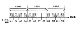
以上のような、使用されていない周波数帯域の推定を行うセンシング技術において、例えば、非特許文献1には、利用対象の周波数帯域内のチャネル数が多い場合に、二段階センシングを行うセンシング方法が開示されている。二段階センシングを行うことで、センシングの効率化を図り、高速に空き周波数帯域を検出することができるようにする。例えば、図1に示すようなチャネル構成を考える。ここでは、チャネル番号C1〜C12に注目して説明する。なお、図1に示す例では、チャネルC7およびC8が使用されていないものとする。 In the sensing technology for estimating a frequency band that is not used as described above, for example, Non-Patent Document 1 discloses a sensing method that performs two-step sensing when the number of channels in the frequency band to be used is large. It is disclosed. By performing two-step sensing, the efficiency of sensing is improved, and a free frequency band can be detected at high speed. For example, consider a channel configuration as shown in FIG. Here, description will be given with attention paid to channel numbers C1 to C12. In the example shown in FIG. 1, it is assumed that channels C7 and C8 are not used.
また、図2は、周波数帯域を分割した周波数ブロックの例を示す説明図である。非特許文献1に記載されたセンシング方法では、まず、図2に示すように、全周波数帯域を複数チャネルを束ねた周波数ブロック(Coarse Sensing Block:CSB)に分割する。図2に示す例では、4つのチャネルを束ねて1つのCSBを構成している。 FIG. 2 is an explanatory diagram illustrating an example of a frequency block obtained by dividing a frequency band. In the sensing method described in Non-Patent Document 1, first, as shown in FIG. 2, the entire frequency band is divided into frequency blocks (Coar Sensing Block: CSB) in which a plurality of channels are bundled. In the example shown in FIG. 2, one CSB is formed by bundling four channels.
そして、一段目のセンシングとして、Coarse Resolution Sensing(Coarseセンシング)と呼ばれるセンシングを実行する。Coarseセンシングは、CSB単位で受信信号電力を算出し、算出した各CSBの受信信号電力を予め定められた第1のしきい値と比較することにより、空きチャネルが存在する周波数ブロックを推定する。 And sensing called Coarse Resolution Sensing (Coarse sensing) is performed as the first-stage sensing. Coarse sensing calculates received signal power in units of CSBs, and compares the calculated received signal power of each CSB with a predetermined first threshold value, thereby estimating a frequency block in which an empty channel exists.
次に、二段階目のセンシングとしてFine resolution Sensing(Fineセンシング)と呼ばれるセンシングを実行する。Fineセンシングは、空きチャネルが存在すると推定されたCSBに含まれる各チャネルについて受信信号電力を算出し、算出した各チャネルの受信信号電力を予め定められた第二のしきい値と比較することにより、空きチャネルを推定する。 Next, sensing called Fine resolution Sensing (Fine sensing) is performed as the second-stage sensing. Fine sensing calculates the received signal power for each channel included in the CSB that is estimated to have an empty channel, and compares the calculated received signal power of each channel with a predetermined second threshold value. Estimate free channels.
図2に示す例では、一段階目のセンシングであるCorseセンシングの結果、CSB2が空きチャネルが存在する周波数ブロックとして推定される。その結果、二段階目のセンシングであるFineセンシングの対象とされ、CSB2に対して二段階目のセンシングであるFineセンシングが実行される。二段目のセンシングであるFineセンシングの結果、チャネルC7およびC8を空きチャネルとする推定結果を得る。 In the example shown in FIG. 2, CSB2 is estimated as a frequency block in which an empty channel exists as a result of the course sensing that is the first-stage sensing. As a result, it is a target of Fine sensing that is second-stage sensing, and Fine sensing that is second-stage sensing is executed on CSB2. As a result of Fine sensing, which is the second-stage sensing, an estimation result is obtained in which channels C7 and C8 are vacant channels.
ところで、センシングを実行する端末局や基地局では、シャドウイングやフェージングなどの電波伝搬環境の変動の影響を受けて受信環境が劣悪となる場合がある。そのような場合には、センシングの検出精度も劣化する。特許文献1には、このシャドウイングやフェージングの影響を軽減することを目的とする、協調センシングを用いた空き周波数帯域の検出方法が記載されている。なお、ここで協調センシングとは、周波数帯域の使用状況を推定する装置以外の装置をも利用して、周波数帯域の使用状況を推定する手法をいい、換言すると複数の装置によって協働してセンシングを行う手法である。 By the way, in a terminal station or base station that performs sensing, the reception environment may be deteriorated due to the influence of fluctuations in the radio wave propagation environment such as shadowing and fading. In such a case, sensing detection accuracy also deteriorates. Patent Document 1 describes a method for detecting a free frequency band using cooperative sensing for the purpose of reducing the effects of shadowing and fading. Here, cooperative sensing refers to a technique for estimating the usage state of a frequency band using a device other than a device that estimates the usage state of a frequency band. In other words, sensing is performed in cooperation with a plurality of devices. It is a technique to do.
特許文献1に記載されている方法は、無線基地局または無線基地局のカバーエリアに存在する複数の無線端末局において、利用対象の全周波数帯域について、無線基地局または無線端末局周辺の受信信号電力の算出や、算出した受信信号電力値を予め設定されたしきい値と比較することにより空き周波数帯域か否かを判定する。そして、それらの算出結果や判定結果を各基地局間で交換することにより自基地局周辺における空き周波数帯域を検出する。また、複数の端末局での算出結果や判定結果を周波数帯域毎に加算平均を行い、空き周波数の検出精度を高めている。 In the method described in Patent Literature 1, a plurality of wireless terminal stations existing in a wireless base station or a coverage area of the wireless base station receive signals around the wireless base station or the wireless terminal station for all frequency bands to be used. It is determined whether or not it is a free frequency band by calculating power and comparing the calculated received signal power value with a preset threshold value. Then, the free frequency band around the base station is detected by exchanging those calculation results and determination results between the base stations. In addition, calculation results and determination results at a plurality of terminal stations are added and averaged for each frequency band to improve the detection accuracy of vacant frequencies.
また、特許文献2には、二段階センシングを採用したコグニティブ無線通信装置において、送信機の送信パワーに応じてセンシング基準レベルを制御する方法が記載されている。このようにセンシング基準レベルを適応的に制御することによって、より高速のセンシングを実行する場合に発生する恐れのある誤検出確率および誤警報確率を減らしている。 Patent Document 2 describes a method of controlling a sensing reference level in accordance with the transmission power of a transmitter in a cognitive radio communication apparatus that employs two-step sensing. By adaptively controlling the sensing reference level in this way, the false detection probability and false alarm probability that may occur when performing higher-speed sensing are reduced.
しかし、特許文献1に記載された協調センシングでは、以下の問題が存在する。まず、受信環境の劣悪なセンシングノードのセンシング結果を用いることにより検出精度が劣化する。また、全てのノードでセンシングを実行するため、センシングノード全体の消費電力量が増加する。さらには、センシングノード数が多くなるため、センシング結果の送信に使用する無線リソース量が増加する。 However, the cooperative sensing described in Patent Document 1 has the following problems. First, detection accuracy deteriorates by using the sensing result of a sensing node having a poor reception environment. Moreover, since sensing is performed in all nodes, the power consumption of the entire sensing node increases. Furthermore, since the number of sensing nodes increases, the amount of radio resources used for transmitting sensing results increases.
特に、利用対象の周波数帯域内のチャネル数が多い場合に、協調センシングに二段階センシングを適用する場合には、上記の問題がより大きなものとなる。 In particular, when the two-stage sensing is applied to the cooperative sensing when the number of channels in the frequency band to be used is large, the above problem becomes more serious.
なお、特許文献2に記載されたセンシング方法は、送信機の送信パワーからプライマリ受信機での干渉量を予測してセンシング基準レベルを設定するものにすぎず、センシングを実行する端末局や基地局におけるシャドウイングやフェージングなどの電波伝搬環境の変動の影響については考慮されていない。このため、センシングを実行している最中にセンシング実行ノードの受信環境が劣悪となってしまった場合には、特許文献1と同様に、そのセンシング結果を用いることにより検出精度が劣化するという問題がある。 Note that the sensing method described in Patent Document 2 is merely a method for setting the sensing reference level by predicting the amount of interference at the primary receiver from the transmission power of the transmitter, and is a terminal station or base station that performs sensing. The effects of fluctuations in the radio wave propagation environment such as shadowing and fading are not considered. For this reason, when the reception environment of the sensing execution node becomes inferior during the sensing, the detection accuracy is deteriorated by using the sensing result as in Patent Document 1. There is.
そこで、本発明は、センシングによる空きチャネルの推定精度の向上と、センシングノード全体の消費電力の低減および無線リソース量の低減とを可能にする無線システム、基地局、端末局、センシング方法および無線機制御プログラムを提供することを目的とする。 Therefore, the present invention provides a radio system, a base station, a terminal station, a sensing method, and a radio device that can improve the estimation accuracy of an empty channel by sensing, reduce the power consumption of the entire sensing node, and reduce the amount of radio resources. An object is to provide a control program.
本発明による無線システムは、他の無線システムの無線機から送信される信号を検出する検出部を備える複数の無線機からの第1の検出動作の結果に基づいて、第1の検出動作の後に行う第2の検出動作の動作パラメータを決定する検出動作パラメータ決定手段と、検出動作パラメータ決定手段によって決定された動作パラメータに従って、第2の検出動作を実行する検出動作実行手段とを備えたことを特徴とする。 The wireless system according to the present invention is based on the result of the first detection operation from a plurality of wireless devices including a detection unit that detects a signal transmitted from the wireless device of another wireless system, after the first detection operation. Detection operation parameter determination means for determining an operation parameter of the second detection operation to be performed, and detection operation execution means for executing the second detection operation in accordance with the operation parameter determined by the detection operation parameter determination means. Features.
また、本発明による基地局は、他の無線システムの無線機から送信される信号を検出する検出部を備える複数の無線機からの第1の検出動作の結果に基づいて、第1の検出動作の後に行う第2の検出動作の動作パラメータを決定する検出動作パラメータ決定手段と、検出動作パラメータ決定手段によって決定された動作パラメータに従って、自無線システムの無線機のうちの1以上の無線機に対して第2の検出動作を行わせるための所定の制御を行う検出動作制御手段と、検出動作制御手段の制御により行われた第2の検出動作の結果に基づいて、他の無線システムに割り当てられたまたは優先的な使用が許可された周波数帯域の使用状況を推定する推定手段とを備えたことを特徴とする。 In addition, the base station according to the present invention performs the first detection operation based on the result of the first detection operation from a plurality of radio devices including a detection unit that detects a signal transmitted from a radio device of another radio system. Detecting operation parameter determining means for determining an operating parameter of the second detecting operation performed after the operation, and for one or more of the wireless devices of the own wireless system according to the operating parameter determined by the detecting operation parameter determining means Detection operation control means for performing predetermined control for causing the second detection operation to be performed, and a result of the second detection operation performed by the control of the detection operation control means. Or an estimation means for estimating a usage state of a frequency band permitted to be used preferentially.
また、本発明による端末局は、自無線システムの基地局および自無線システムの他の端末局と通信可能な端末局であって、他の無線システムの無線機から送信される信号を検出する検出部を備える複数の無線機からの第1の検出動作の結果に基づいて、第1の検出動作の後に行う第2の検出動作の動作パラメータを決定する検出動作パラメータ決定手段と、検出動作パラメータ決定手段によって決定された動作パラメータに従って、自無線システムの無線機のうちの1以上の無線機に対して第2の検出動作を行わせるための所定の制御を行う検出動作制御手段と、検出動作制御手段の制御により行われた第2の検出動作の結果に基づいて、他の無線システムに割り当てられたまたは優先的な使用が許可された周波数帯域の使用状況を推定する推定手段とを備えたことを特徴とする。 The terminal station according to the present invention is a terminal station that can communicate with a base station of the own radio system and another terminal station of the own radio system, and detects a signal transmitted from a radio device of the other radio system. A detection operation parameter determination unit that determines an operation parameter of a second detection operation performed after the first detection operation based on a result of the first detection operation from a plurality of wireless devices including a unit; and a detection operation parameter determination Detection operation control means for performing predetermined control for causing one or more radio apparatuses of the own radio system to perform the second detection operation according to the operation parameter determined by the means, and detection operation control Based on the result of the second detection operation performed by the control of the means, the usage status of the frequency band allocated to other wireless systems or permitted to be used preferentially is estimated. Characterized by comprising a constant section.
また、本発明によるセンシング方法は、他の無線システムの無線機から送信される信号を検出する検出部を備える複数の無線機からの第1の検出動作の結果に基づいて、第1の検出動作の後に行う第2の検出動作のパラメータを決定し、決定された動作パラメータに従って、第2の検出動作を行い、第2の検出動作の結果に基づいて、他の無線システムに割り当てられたまたは優先的な使用が許可された周波数帯域の使用状況を推定することを特徴とする。 In addition, the sensing method according to the present invention provides a first detection operation based on a result of the first detection operation from a plurality of wireless devices including a detection unit that detects a signal transmitted from a wireless device of another wireless system. The parameter of the second detection operation to be performed after is determined, the second detection operation is performed according to the determined operation parameter, and assigned or prioritized to another wireless system based on the result of the second detection operation It is characterized in that the use situation of a frequency band permitted to be used is estimated.
また、本発明による無線機制御プログラムは、コンピュータに、他の無線システムの無線機から送信される信号を検出する検出部を備える複数の無線機からの第1の検出動作の結果に基づいて、第1の検出動作の後に行う第2の検出動作の動作パラメータを決定する処理、および決定された動作パラメータに従って、自無線システムの無線機のうちの1以上の無線機に対して第2の検出動作を行わせるための所定の制御処理を実行させることを特徴とする。 Further, the wireless device control program according to the present invention is based on the result of the first detection operation from a plurality of wireless devices including a detection unit that detects a signal transmitted from a wireless device of another wireless system. Processing for determining an operation parameter of a second detection operation performed after the first detection operation, and second detection for one or more radio devices of the radio device of the own radio system according to the determined operation parameter A predetermined control process for performing the operation is executed.
本発明によれば、センシングによる空きチャネルの推定精度の向上と、センシングノード全体の消費電力の低減および無線リソース量の低減とを可能にする。 According to the present invention, it is possible to improve the estimation accuracy of empty channels by sensing, reduce the power consumption of the entire sensing node, and reduce the amount of radio resources.
実施形態1.
以下、本発明の実施形態を図面を参照して説明する。本実施形態では、自無線システムの基地局または該基地局のカバーエリア(該基地局と通信または放送が可能な地域)に存在するセンシング装置(例えば、端末局)が、他の無線システムが利用対象の周波数帯域を利用しているか否かを、複数の端末局によるCoarseセンシングと、その結果により選別された端末局によるFineセンシングとを用いた協調二段階センシングにより推定する。
Embodiment 1. FIG.
Hereinafter, embodiments of the present invention will be described with reference to the drawings. In the present embodiment, a sensing device (for example, a terminal station) existing in the base station of the own wireless system or the coverage area of the base station (area where communication or broadcasting with the base station is possible) is used by other wireless systems. Whether or not the target frequency band is used is estimated by cooperative two-step sensing using coarse sensing by a plurality of terminal stations and fine sensing by terminal stations selected based on the result.
図3は、本実施形態における自無線システムと他の無線システムの関係を示す説明図である。なお、図3では、本実施形態の無線システム12の一例と、他の無線システム11の一例とを示している。また、それらを併せて無線システム10として示している。
FIG. 3 is an explanatory diagram showing a relationship between the own wireless system and another wireless system in the present embodiment. In FIG. 3, an example of the
他の無線システム11は、システム帯域として、例えば、図1に示すような周波数帯域が割り当てられているまたは優先的な使用が許可されているものとし、その周波数帯域内を複数チャネルに分割して使用しているものとする。また、他の無線システム11は、基地局101や端末局(図示せず。)を備えている。
The
本実施形態の無線システム12(以下、自無線システム12という。)は、基地局201と端末局202とを備える。基地局201は、そのカバーエリアが他の無線システム11の基地局101のカバーエリアの周辺またはオーバーラップするように配置されている。なお、図3では、基地局201のカバーエリア内に端末局202−1と202−2とが存在している例を示しているが、端末局202の数はいくつであってもよい。
The wireless system 12 (hereinafter referred to as the own wireless system 12) of the present embodiment includes a
次に、端末局202の機能について簡単に説明する。本実施形態の端末局202は、自無線システム12の基地局201と通信する機能と、他の無線システム11が使用する周波数帯域をセンシングする機能とを具備している。端末局202は、例えば、基地局201の指示に基づいて利用対象の周波数帯域をセンシングする。また、端末局202は、センシング結果(例えば、当該端末局202において検出した、ある指定された周波数帯域の受信信号電力値)を自無線システム12の基地局201に送信する。
Next, the function of the
なお、本実施形態では、センシング動作を複数の周波数解像度で実行する。例えば、端末局202は、基地局201から複数のチャネルを束ねた周波数ブロック単位でセンシングを行うよう指示があった場合には、Coarseセンシングを行い、周波数ブロック単位の受信信号電力値をセンシング結果として自無線システム12の基地局201に送信する。
In the present embodiment, the sensing operation is executed with a plurality of frequency resolutions. For example, when the
また、例えば端末局202は、基地局201から特定の周波数ブロック内のチャネル単位でセンシングを行うよう指示があった場合には、その特定の周波数ブロック内の各チャネルに対してFineセンシングを行い、チャネル単位の受信信号電力値をセンシング結果として自無線システム12の基地局201に送信する。
Further, for example, when the
次に、基地局201の機能について簡単に説明する。基地局201は、当該基地局201からのセンシング指示に応じて実行された各端末局202でのセンシングの結果に基づいて、利用対象の周波数帯域(ここでは、他の無線システム11に割り当てられているまたは他の無線システム11に優先的な使用が許可されている周波数帯域)の使用状況を推定する。なお、当該基地局201においてもセンシングを行うことも可能である。その場合、当該基地局201のセンシング結果も合わせて用いて、利用対象の周波数帯域の使用状況を推定する。また、基地局201は、推定結果に基づき、自無線システム12における通信または放送についての無線リソース管理(例えば、使用する周波数帯域の選択や送信電力制御や通信方式,変調方式,符号化率等の管理)を行う。
Next, the function of the
なお、本実施形態では、使用状況の推定を複数の周波数解像度により実行する。より具体的には、周波数ブロック単位の使用状況の推定と、チャネル単位の使用状況の推定とを行う。基地局201は、利用対象の周波数帯域を複数チャネルが束ねられた周波数ブロックを単位に複数に分割し、各端末局202に、周波数ブロック単位でのCoarseセンシングを実行するように指示する。そして、各端末局202から収集した各周波数ブロックのCoarseセンシングの結果を元に、空きチャネルが存在する周波数ブロックを推定する。このとき、基地局201は、各端末局202から収集したCoarseセンシング結果に基づいて、センシング検出精度が高いと予想される端末局を決定し、その端末局のCoarseセンシング結果を用いて周波数ブロック単位での周波数使用状況を推定する。また、基地局201は、センシング検出精度が高いと予想された端末局を、Fineセンシングを実行させるノード(またはその候補ノード)に決定する。
In the present embodiment, the usage state is estimated with a plurality of frequency resolutions. More specifically, estimation of the usage status in units of frequency blocks and estimation of the usage status in units of channels are performed. The
そして、基地局201は、決定されたノードの情報と、周波数ブロック単位での周波数使用状況の推定結果とを元に、Fineセンシングの指示を行う。例えば、無線リソースが許す範囲内において、できるだけセンシング検出精度が高いと予想された端末局202に、空きチャネルが存在すると推定された周波数ブロックに対してチャネル単位でのFineセンシングを実行するように指示する。そして、Fineセンシングを実行した端末局202から収集したFineセンシング結果に基づいて、空きチャネルを推定する。
Then, the
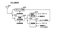
次に、端末局202および基地局201の構成について説明する。まず、端末局202の構成について説明する。図4は、端末局202の構成例を示すブロック図である。本実施形態の端末局202は、それぞれ送受信アンテナ301と、センシング・無線送受信切替部(第1のスイッチ)302と、センシング部303と、無線送受信部304と、復調・変調切替部(第2のスイッチ)305と、復調/復号部306と、変調部307とを備える。
Next, configurations of the
送受信アンテナ301は、無線信号を受信し、かつ送信することが可能な送受信兼用のアンテナである。送受信アンテナ301の受信機能は、他の無線システム11の基地局101からの無線信号を受信する機能(センシング時受信機能)と、自無線システム12の基地局201からの無線信号を受信する機能(通常時受信機能)とを含む。送受信アンテナ301の送信機能は、自無線システム12の基地局201へ無線信号を送信する機能を含む。ここで、送受信アンテナ301は、受信用アンテナと送信用アンテナとに分かれた構成であってもよい。
The transmission /
センシング・無線送受信切替部302は、センシングを行う場合には、送受信アンテナ301とセンシング部303とを接続し、一方、自無線システム12の基地局201との間で無線通信を行う場合には、送受信アンテナ301と無線送受信部304とを接続する。
When performing sensing, the sensing / radio transmission /
センシング部303は、基地局201からの指示に応じて、利用対象の周波数帯域のセンシングを行う。より具体的には、他の無線システム11の基地局101から受信する信号から、その基地局が使用する周波数帯域における受信信号電力値を算出する。センシング部303は、この受信信号電力値をセンシング結果として出力する。なお、このセンシング結果は、変調部307、復調・変調切替部305、無線送受信部304、センシング・無線送受信切替部302および送受信アンテナ301を介して自無線システム12の基地局201に送信される。
The
無線送受信部304は、自無線システム12の基地局201との間で無線信号を送受信する際に必要な信号処理を行う。通信または放送に使用される周波数帯域情報を入力として、使用周波数帯域に合わせて、受信処理および送信処理を行う。より具体的には、受信処理時には、送受信アンテナ301を介して受信された無線信号に対して、受信電力の増幅、ダウンコンバート、A/D(アナログ/デジタル)変換等の処理を行う。なお、当該処理後の信号は、デジタルの受信信号として、復調・変調切替部305を介して復調/復号部306に入力される。また、送信処理時には、復調・変調切替部305を介して入力される信号(デジタルの送信信号)に対して、D/A(デジタル/アナログ)変換、アップコンバート、送信電力増幅等の処理を行う。なお、該処理後の信号は、アナログの送信信号として、センシング・無線送受信切替部302を介して送受信アンテナ301に入力されて、送受信アンテナ301から基地局201に送信される。
The wireless transmission /
復調・変調切替部305は、送信時と受信時とで入力信号の出力先を切り替えるスイッチ部である。復調・変調切替部305は、受信処理時には、無線送受信部304と復調/復号部306とを接続し、送信処理時には、変調部307と無線送受信部304とを接続する。
The demodulation /
復調/復号部306は、復調・変調切替部305を介して無線送受信部304から入力される信号(受信信号)に対して復調および復号処理を行う。なお、この復調および復号処理によって、受信信号に含まれていたユーザデータや制御信号を得る。ここで、ユーザデータや制御信号は、例えば上位レイヤに出力される。なお、上位レイヤでは、入力されるユーザデータや制御信号に基づいて、当該端末局が実装している機能に関する種々の動作(通話処理や各種アプリケーションの実行等)を行う。また、制御信号が後述のセンシング制御信号である場合には、センシング部303に入力してもよい。なお、センシング制御信号も上位レイヤを介して、センシング部303に入力されるようになっていてもよい。上位レイヤを介す場合には、上位レイヤの例えば、信号制御部が、センシング周期やセンシング対象を管理し、適宜センシング部303に制御指示を出すようにしてもよい。
Demodulation /
変調部307は、センシング部303または上位レイヤから入力される送信信号(例えば、ユーザデータ、制御信号、パイロット信号、センシング結果等)に対して、符号化、インターリーブ、変調、マッピング等の処理を行う。なお、当該処理後の信号(送信信号)は、復調・変調切替部305を介して無線送受信部304に入力される。
The
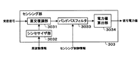
図5は、センシング部303の構成例を示すブロック図である。図5に示すセンシング部303は、直交復調部3031と、シンセサイザ3032と、バンドパスフィルタ3033と、電力値算出部3034とを備える。
FIG. 5 is a block diagram illustrating a configuration example of the
シンセサイザ3032は、入力される周波数情報に基づいて周波数信号を生成する。なお、生成した周波数信号は、直交復調部3031に出力される。
The
直交復調部3031は、センシング・無線送受信切替部302を介して送受信アンテナ301から入力される無線信号(受信した無線信号)を、シンセサイザ3032から入力される周波数信号を用いて復調する。なお、復調した信号は、バンドパスフィルタ3033に入力される。
The
バンドパスフィルタ3033は、入力される信号から所望の周波数帯域幅の信号を抽出する。バンドパスフィルタ3033は、基地局201からのセンシング指示に従って、直交復調部3031から入力される信号(センシング対象の無線信号)から所望の周波数帯域幅の信号を抽出する。具体的には、センシングを行う周波数解像度(Coarseセンシングか、Fineセンシングか)と、周波数帯域幅とによって適応的に通過帯域を変更させることにより、信号を抽出する。バンドパスフィルタ3033によって抽出された信号は、後段の電力値算出部3034に入力される。
The
電力値算出部3034は、バンドパスフィルタ3033から入力される信号の信号電力のレベルを算出する。また、算出した値を信号電力値として出力する。信号電力値は、センシング結果として、復調部307および無線送受信部304を介して自無線システム12の基地局201に送信される。送信情報としては、信号電力値をそのまま送信してもよいし、特定の信号形式(例えば、符号化や量子化など)に変換して送信してもよい。
The power
ここで、センシング対象の周波数帯域が複数存在し、複数の信号電力値を算出する場合には、各周波数帯域に合わせてバンドパスフィルタの通過帯域を変更し、その出力を用いて、信号電力値を算出すればよい。 Here, when there are multiple frequency bands to be sensed and multiple signal power values are calculated, the passband of the bandpass filter is changed according to each frequency band, and the output is used to change the signal power value. May be calculated.
次に、基地局201の構成例について説明する。図6は、図3に示す自無線システム12の基地局201の受信系の構成例を示すブロック図である。基地局201は、受信系の構成要素として、受信用アンテナ401と、無線受信部402と、復調/復号部403と、センシング結果切替部(スイッチ)404と、電波検出用アンテナ405と、センシング部406と、ノード決定部407と、周波数ブロック決定部408と、信号検出部409と、センシング制御部410と、無線リソース管理部411とを備える。
Next, a configuration example of the
受信用アンテナ401は、自無線システム12の端末局から送波される無線信号を受信する。受信用アンテナ401で受信された無線信号は、無線受信部402に入力される。
The receiving
無線受信部402は、自無線システム12の端末局202から無線信号を受信する際に必要な信号処理を行う。より具体的には、受信用アンテナ401を介して受信した無線信号に対して、受信電力増幅、ダウンコンバート、A/D変換等の処理を行う。なお、当該処理後の信号は、デジタルの受信信号として、復調/復号部403に入力される。
The
復調/復号部403は、入力される信号(受信信号)に対して復調および復号処理を行う。なお、この復調および復号処理によって、受信信号に含まれていたユーザデータや制御信号、センシング結果を得る。ここで、ユーザデータや制御信号は、例えば上位レイヤに出力される。一方、センシング結果は、センシング結果切替部部404に入力される。、センシング結果は、例えば、端末局202における受信信号電力値である。
The demodulation /
また、基地局201においても他の無線システム11のセンシングを行なう場合には、センシング部406が、電波検出用アンテナ405で受信された無線信号を用いてセンシング対象の周波数帯域の受信信号電力の算出を行い、この算出結果(センシング結果)も併せて、センシング結果切替部404に入力されるようにすればよい。なお、センシング部406の構成は、端末局202におけるセンシング部303(図5参照。)と同様でよい。なお、基地局201において他の無線システム11のセンシングを行わない場合には、基地局201の構成のうち電波検出用アンテナ405とセンシング部406とを省略してもよい。
When the
センシング結果切替部404は、復調/復号部403やセンシング部406から入力されるセンシング結果の出力先を、センシング段階、すなわち現在実行中のセンシングの周波数解像度(CoarseセンシングかFineセンシングかのセンシングの種類)に応じて切り換える。なお、センシング結果404への切り替え指示を、後述のセンシング制御部410が行うようにしてもよい。
The sensing
センシング結果切替部404は、センシング段階としてCoarseセンシングを実行している場合には、センシング結果をノード決定部407と周波数ブロック決定部408に出力する。一方、Fineセンシングを実行している場合には、センシング結果を信号検出部409に出力する。なお、センシング結果にどのセンシングによる結果かを示す情報が付与されている場合には、その情報に基づいて出力先を切り替えてもよい。
The sensing
ノード決定部407は、入力されるCoarseセンシング結果(各端末局202から収集したセンシング結果と当該基地局201でもCoarseセンシングを行った場合にはその結果とを含む)に基づいて、次のセンシング段階であるFineセンシングの実行ノードとする端末局(以下、Fineセンシング実行ノードという。)を決定する。例えば、ノード決定部407は、Fineセンシングを行う端末局の決定のために予め定められている所定のノード決定しきい値情報を入力とし、その値を「ノード決定しきい値」として設定する。そして、Coarseセンシング結果である周波数ブロック単位の受信信号電力とノード決定しきい値とを比較し、しきい値以上となるセンシング結果を送信した端末局をFineセンシング実行ノードと決定してもよい。Fineセンシング実行ノードを決定すると、ノード決定部407は、Fineセンシング実行ノードの情報をノード決定情報としてセンシング制御部410に出力する。なお、本例では、周波数ブロック決定部408にも出力する。ノード決定情報は、例えば、Fineセンシング実行ノードの端末局IDとしてもよい。
Based on the input coarse sensing result (including the sensing result collected from each
ここで、ノード決定しきい値情報は、他の無線システム11の基地局101の送信電力情報や、基地局101から自無線システム12の基地局201または端末局202までの距離、1つの周波数ブロック内に含まれるチャネル数などを考慮して予め設定されるものとする。例えば、基地局101と基地局201間の距離と、基地局101の送信電力値とから、秦式などの伝搬損算出式により求めた受信信号電力に所定のオフセットを加えた値に設定してもよい。また、ノード決定しきい値情報は、自無線システムで要求する周波数帯域幅によって可変としてもよい。例えば、要求する周波数帯域が狭い場合にはノード決定しきい値を低く設定し、逆に広い場合にはノード決定しきい値を高く設定するといったように調整可能である。さらに、端末局202からのセンシング結果を元にノード決定しきい値を補正してもよい。例えば、所定のノード数が選択されるように、可変の値とすることも可能である。
Here, the node determination threshold information includes the transmission power information of the
なお、当該基地局201のセンシングノードとしての取り扱いについては、端末局202と同列に扱ってもよいし、別扱いとしてもよい。例えば、基地局のセンシング結果も含め、それぞれのCoarseセンシング結果によりFineセンシング実行ノードを決定するようにしてもよいし、当該基地局201のセンシング結果の通知には無線リソースを必要としないため、当該基地局201は常にFineセンシング実行ノードに含まれるようにしてもよい。
In addition, about the handling as the sensing node of the said
周波数ブロック決定部408は、端末局202から収集したCoarseセンシング結果(当該基地局201でもCoarseセンシングを行った場合にはその結果も含む)と、ノード決定部407から入力されるノード決定情報とに基づいて、次のセンシング段階であるFineセンシングを行う周波数ブロック(以下、Fineセンシング実行周波数ブロックという。)を決定する。例えば、周波数ブロック決定部408は、Fineセンシングを行う周波数ブロックの決定のために予め定められている所定の周波数ブロック決定しきい値情報を入力として、その値を「周波数ブロック決定しきい値」として設定する。そして、ノード決定部407から出力されるノード決定情報によって示されるFineセンシング実行ノードのセンシング結果である受信信号電力を用いて、受信信号電力と周波数ブロック決定しきい値とを比較し、しきい値未満となる周波数ブロックをFineセンシング実行周波数ブロックと決定してもよい。Fineセンシング実行周波数ブロックを決定すると、ノード決定部407は、Fineセンシング実行周波数の情報を周波数ブロック決定情報としてセンシング制御部410に出力する。周波数ブロック決定情報は、例えば、周波数ブロック番号としてもよい。
The frequency
ここで、周波数ブロック決定しきい値情報は、ノード決定しきい値情報と同様に、他の無線システム11の基地局101の送信電力情報や、基地局101から自無線システム12の基地局201または端末局202までの距離、1つの周波数ブロック内に含まれるチャネル数などを考慮して予め設定されるものとする。また、周波数ブロック決定しきい値情報は、自無線システム12で要求する周波数帯域幅によって可変としてもよい。例えば、要求する周波数帯域が狭い場合には周波数ブロック決定しきい値を低く設定し、逆に広い場合には周波数ブロック決定しきい値を高く設定するといったように調整可能である。さらに、収集したセンシング結果を元に周波数ブロック決定しきい値を補正してもよい。例えば、所定の周波数ブロック数が選択されるように、可変の値とすることも可能である。
Here, the frequency block determination threshold information is similar to the node determination threshold information, such as the transmission power information of the
ここで、周波数ブロック決定部408は、同一の周波数ブロックについて複数のセンシング結果が得られる場合には、その複数のセンシング結果を用いてFineセンシング実行周波数ブロックの決定を行うことも可能である。例えば、同一の周波数ブロックについて得られた複数の受信信号電力値の平均値(加算平均値あるいは重み付け加算平均値)を算出し、算出した平均値を用いてFineセンシング実行周波数ブロックの決定を行ってもよい。なお、複数の端末局としては、Fineセンシング実行ノードに限定してもよいし、Coarseセンシングを実行した全端末局としてもよい。
Here, when a plurality of sensing results are obtained for the same frequency block, the frequency
また、重み付け加算平均値を算出する際に用いる重み係数は、各センシング結果の信頼度に応じて設定することができる。例えば、端末局が自身の現在位置を認識している状況において端末局と基地局との間の距離や端末局クラスの大小、受信信号電力値の大小、前回のセンシング実行時からの時間間隔の大小などにより設定することが可能である。 Moreover, the weighting coefficient used when calculating the weighted average value can be set according to the reliability of each sensing result. For example, in the situation where the terminal station recognizes its current position, the distance between the terminal station and the base station, the size of the terminal station class, the magnitude of the received signal power value, the time interval from the previous sensing execution It can be set depending on the size.
この場合、例えば、周波数ブロック決定部408に、Fineセンシング実行周波数ブロックを決定する前に、入力される受信信号電力値の重み付け加算平均値を算出する機能を追加すればよい。または、周波数ブロック決定部408の前段に、そのような算出を行う算出部を設けてもよい。周波数ブロック決定部408は、算出された重み付け加算平均値を用いて周波数ブロック決定しきい値との比較を行えばよい。
In this case, for example, a function for calculating a weighted average value of received signal power values to be input may be added to the frequency
一方、センシング結果切替部404は、センシング段階としてFineセンシングを実行している場合には、センシング結果を信号検出部409に出力する。
On the other hand, the sensing
信号検出部409は、入力されるFineセンシング結果に基づいて信号検出を行う。信号検出部409は、例えば、他の無線システム11において予め定められている所定の受信信号電力値情報を信号検出しきい値情報として入力し、その値を「信号検出しきい値」として設定する。そして、受信信号電力と信号検出しきい値とを比較し、しきい値未満となるチャネルを空きチャネルと判定してもよい。また、信号検出部409は、判定結果を示す情報を「使用状況推定結果」として無線リソース管理部411に出力する。使用状況推定結果は、例えば、各チャネルにおいて、しきい値以上の場合に1とし、しきい値未満の場合に0とするような、使用有無の推定結果を示す情報であってもよい。なお、ここでも前述のように、同一のチャネルについて複数のセンシング結果が得られる場合には、複数のセンシング結果の平均値(加算平均値あるいは重み付け加算平均値)を算出し、算出された重み付け加算平均値を用いて信号検出を行うことも可能である。
The
ここで、他の無線システム11において予め定められている所定の受信信号電力値情報は、他の無線システム11において規定される所要の受信信号電力値であってもよい。さらに、固定値であっても可変値であってもよい。この値は、予め他の無線システム11の規定情報を入手して設定してもよいし、可変値の場合には変更になる度に他の無線システム11の規定情報を入手して設定してもよい。情報の入手方法としては、他の無線システム11に有線または無線にて接続して入手する方法や規定値が格納されているデータベースなどにアクセスして入手する方法等を挙げることができる。
Here, the predetermined received signal power value information predetermined in the
なお、信号検出部409の処理は判定処理であるが、信号検出部409の出力結果はあくまで推定値である。なぜなら、周波数帯域の使用の有無の判定結果は、信号検出しきい値に依存する推定値であって、使用状況を100パーセント反映するものではないからである。本明細書では、信号検出部409内部の処理について「判定」という場合と、信号検出部409の出力結果について「推定」という場合とがあるが、それによって処理の内容や情報の内容が異なることを意味しているものではない。
In addition, although the process of the
無線リソース管理部411は、信号検出部409から出力される使用状況推定結果に基づいて、基地局201と端末局202との通信または放送に使用する無線リソースの管理(例えば、使用する周波数帯域の選択、送信電力制御、通信方式や変調方式や符号化率等の管理)を行う。無線リソース管理部411は、例えば、無線リソースの管理の一つとして、信号検出部409から出力される使用状況推定結果を用いて、自無線システム12が使用する周波数帯域を決定してもよい。なお、空き周波数帯域の判定までを信号検出部409が行い、判定結果を無線リソース管理部411に入力してもよい。また、無線リソース管理部411は、管理している無線リソースの現在の状態を示す情報を含む無線リソース管理情報を適宜出力する。この無線リソース管理情報は、センシング制御部410にも入力される。無線リソース管理部411は、例えば、他の処理部から要求があった場合や内容に変更が生じた場合に無線リソース管理情報を出力してもよい。
Based on the use state estimation result output from the
センシング制御部410は、ノード決定部407と、周波数ブロック決定部408と、無線リソース管理部411とからの出力に基づいて、端末局(当該基地局201がセンシング部406を備える場合は、センシング部406を含む。)に実行させるセンシングを制御する。センシング制御部410は、より具体的には、センシング段階(センシング周波数解像度)の管理、センシングの詳細の決定、指示を行う。本実施形態では、例えば、Coarseセンシングを実行中の場合には、ノード決定部407と、周波数ブロック決定部408から、Fineセンシングを実行する端末局と周波数ブロックの情報(ノード決定情報と周波数ブロック決定情報)が出力されるので、その情報と、無線リソース管理部411から出力される無線リソース管理情報とを用いて、端末局202の中からFineセンシングを実行する端末局にどの周波数ブロックをFineセンシングするかといった詳細を決定し、それを指示するための制御情報を生成する。
Based on the outputs from the
ここで、複数の端末局がFineセンシング実行ノードとして選択され、複数の周波数ブロックがFineセンシング実行周波数ブロックとして選択された場合であって、センシング制御情報やセンシング結果の送信に使用できる無線リソース量が限られている場合のセンシング制御について説明する。 Here, when a plurality of terminal stations are selected as Fine sensing execution nodes and a plurality of frequency blocks are selected as Fine sensing execution frequency blocks, the amount of radio resources that can be used for transmission of sensing control information and sensing results is Sensing control in a limited case will be described.
まず、一度にFineセンシングを実行可能な周波数ブロック数がNである場合に、Fineセンシング実行周波数ブロック数がM(N<M)である場合について説明する。 First, when the number of frequency blocks that can execute Fine sensing at a time is N, a case where the number of Fine sensing execution frequency blocks is M (N <M) will be described.
この場合の周波数ブロックの選択方法としては、直前の通信を行ったタイミングで自無線システム12が利用している周波数ブロックのFineセンシングを優先的に実行することが望ましい。これは、前回のセンシング時に他の無線システム11が使用していないと推定して自無線システム12が利用を開始したとして、その後、他の無線システム11が使用を開始した場合には、他の無線システム11に干渉を与えるためである。すなわち、他の無線システム11に干渉を与えることがないように、他の無線システム11が引き続き使用していないことを確認する重要性が高いためである。
As a method for selecting a frequency block in this case, it is desirable to preferentially execute Fine sensing of the frequency block used by the
その他の周波数ブロックの選択方法としては、過去一定時間内での自無線システム12の利用回数が多いものや利用時間が長いもの、前回のFineセンシング実行タイミングからの経過時間が長いもの、Fineセンシング周波数ブロックと決定されてからの経過時間が長いものまたは短いものなどの選択指標を用いて、Fineセンシングの実行周波数ブロックを、可能な周波数ブロック数Nになるまで選択する方法が適用できる。なお、ランダムに周波数ブロックを選択する方法や周波数ブロック番号の大きい順、または小さい順に所定数Nだけ選択する方法も適用可能である。
Other frequency block selection methods include those in which the number of times the
次に、一度にFineセンシングを実行可能な端末局数がNである場合に、Fineセンシング実行ノード数がM(N<M)である場合について説明する。なお、Fineセンシングを実行可能な端末局数は、センシング制御情報やセンシング結果の送信に使用できる無線リソース量(R)と、1つの端末局がFineセンシングを実行するのに必要な無線リソース量(r)とにより、R/rで決定される。なお、Rやrとは予め定めておいてもよいし、その都度定めてもよい。また、予め定める場合であっても、複数のサイズを規定しておき、可変とすることも可能である。 Next, a case where the number of terminal stations that can perform Fine sensing at a time is N and the number of Fine sensing execution nodes is M (N <M) will be described. Note that the number of terminal stations that can perform Fine sensing includes the amount of radio resources (R) that can be used to transmit sensing control information and sensing results, and the amount of radio resources that one terminal station needs to perform Fine sensing ( r) and R / r. R and r may be determined in advance or may be determined each time. Even if it is determined in advance, a plurality of sizes can be defined and made variable.
この場合(N<Mの場合)には、Fineセンシング実行ノードの受信信号電力値の高い順に、所定数Nだけ選択する方法を適用する。これは、受信信号電力値が高い端末局は受信環境が良好であり、センシング検出精度が高いと予想されるためである。 In this case (when N <M), a method of selecting a predetermined number N in descending order of the received signal power value of the Fine sensing execution node is applied. This is because a terminal station with a high received signal power value is expected to have a good reception environment and high sensing detection accuracy.
この他にも、過去一定時間内でのセンシング回数の多い順または少ない順や、端末局が搭載するバッテリ容量の大きい順などの選択指標を用いて、Fineセンシング実行可能な端末局数Nまで選択する方法が適用可能である。例えば、過去一定時間内でのセンシング回数の多い順を選択指標に用いる場合には、センシングを実行する価値が大きい端末局に優先的にセンシングを実行させることができる。センシング回数の多い端末局は、電波伝搬環境の変動が大きい場所に存在する可能性が高いと推定されるため、高頻度にセンシングを行うことでその変動を検出しやすくなるためである。また、例えば過去一定時間内でのセンシング回数の少ない順を選択指標に用いる場合には、全端末局でのセンシング回数が等しくなるように制御することができ、特定の端末局のセンシングによる消費電力量が増加することを回避することができる。また、例えば、端末局が搭載するバッテリ容量の大きい順を選択指標に用いる場合には、バッテリ容量の少ない端末局のセンシングによる消費電力量を抑えることができる。なお、ランダムに端末局を選択する方法や端末局IDの大きい順または小さい順に所定数Nだけ選択する方法も適用可能である。 In addition, the number of terminal stations that can perform Fine sensing is selected up to N using selection indexes such as the order in which the number of times of sensing in the past fixed time is large or small, or the order in which the battery capacity installed in the terminal station is large. The method to do is applicable. For example, when the order in which the number of times of sensing in the past certain time is large is used as the selection index, it is possible to preferentially execute sensing to a terminal station having a large value for performing sensing. This is because a terminal station with a large number of sensing times is estimated to be likely to exist in a place where the fluctuation of the radio wave propagation environment is large, so that it is easy to detect the fluctuation by sensing frequently. Also, for example, when using the order in which the number of times of sensing in the past fixed time is as a selection index, the number of times of sensing at all terminal stations can be controlled to be equal, and the power consumption due to sensing at a specific terminal station can be controlled. An increase in the amount can be avoided. Further, for example, when using the order in which the battery capacity installed in the terminal station is large as the selection index, it is possible to suppress power consumption due to sensing of the terminal station having a small battery capacity. Note that a method of selecting a terminal station at random or a method of selecting a predetermined number N in order of increasing or decreasing terminal station ID is also applicable.
図7は、基地局201の送信系の構成例を示すブロック図である。基地局201は、送信系の構成要素として、制御信号生成部412と、変調部413と、無線送信部414と、送信用アンテナ415とを備える。
FIG. 7 is a block diagram illustrating a configuration example of a transmission system of the
制御信号生成部412は、通信または放送のために、上位レイヤの制御部(図示せず。)や無線リソース管理部411から送られてくる無線リソース管理情報を含む制御信号と、センシング制御部410から送られてくるセンシング制御信号とを入力し、通信用フォーマットに合わせた制御信号を生成し出力する。ここで、センシング制御信号とは、センシングに関する指示情報であって、例えば、センシングを行う端末局(センシング実行ノード)の情報や、センシングを行う周波数の周波数ブロック(センシング実行周波数ブロック)またはチャネルの情報、センシングを行うタイミングや周期についての情報などである。
The control
変調部413は、制御信号生成部412または上位レイヤから入力される送信信号(例えば、制御信号、ユーザデータ、パイロット信号等)に対して、符号化、インターリーブ、変調、マッピング等の処理を行う。なお、当該処理後の信号(送信信号)は、無線送信部414に入力される。
The
無線送信部414は、通信または放送に使用される周波数帯域情報を入力として、使用周波数帯域に合わせて、自無線システム12の端末局202との間で無線信号を送信する際に必要な信号処理を行う。具体的には、変調部413から入力される送信信号に対して、D/A変換やアップコンバート、送信電力増幅等の処理を行う。なお、当該処理実行後の信号は、送信用アンテナ415に入力されて、送信用アンテナ415から各端末局202に送信される。
The
ここで、基地局201において、電波検出用アンテナ405と受信用アンテナ401とを共通の1つのアンテナとすることも可能である。この場合、共通アンテナを使用用途(例えば、センシング時受信または通常時受信)に応じて時分割に使用することができる。さらに、電波検出用アンテナ405と受信用アンテナ401と送信用アンテナ415とを共通の1つのアンテナとすることもできる。この場合、共通アンテナを使用用途(例えば、センシング受信や通常受信または通常送信)に応じて時分割に使用することができる。
Here, in the
次に、Fineセンシング実行ノードの決定およびFineセンシング実行周波数ブロックの決定動作について、具体例を用いて説明する。ここでも、図1に示すチャネル構成において、図2に示すように全周波数帯域を複数チャネル束ねた周波数ブロック(CSB)に分割する場合を例に用いて説明する。 Next, the determination operation of the Fine sensing execution node and the determination operation of the Fine sensing execution frequency block will be described using a specific example. Here, the case where the channel configuration shown in FIG. 1 is divided into frequency blocks (CSB) in which the entire frequency band is bundled as shown in FIG. 2 will be described as an example.
図8は、ノード決定部407におけるFineセンシングノードの決定の一例を示す説明図である。なお、図8(a)は端末局202−1から受信したCoarseセンシング結果の一例を示す説明図であり、図8(b)は端末局202−2から受信したCoarseセンシング結果の一例を示す説明図である。ノード決定部407は、例えば、各端末局202から収集した周波数ブロック単位の受信信号電力をノード決定しきい値と比較する。図8(a)に示す例では、端末局202−1のCoarseセンシング結果は、CSB1およびCSB3の受信信号電力がノード決定しきい値以上となっている。一方、図8(b)に示す例では、端末局202−2のCoarseセンシング結果は、いずれのCSBの受信信号電力もノード決定しきい値以上となっていない。このような場合、ノード決定部407は、周波数ブロックの受信信号電力が1つでもノード決定しきい値以上となるセンシング結果を通知した端末局202(本例では、端末局202−1のみ)をFineセンシング実行ノードと決定してもよい。
FIG. 8 is an explanatory diagram illustrating an example of determining a Fine sensing node in the
また、図9は、周波数ブロック決定部408におけるFineセンシング実行周波数ブロックの決定の一例を示す説明図である。周波数ブロック決定部408は、例えば、Fineセンシング実行ノードに決定された端末局202−1の各周波数ブロックの受信信号電力を周波数ブロック決定しきい値と比較する。図9に示す例では、端末局202−1のCoarseセンシング結果は、CSB2の受信信号電力が周波数ブロック決定しきい値未満となっている。このような場合、周波数ブロック決定部408は、CSB2をFineセンシング実行周波数ブロックと決定してもよい。
FIG. 9 is an explanatory diagram showing an example of determining a Fine sensing execution frequency block in the frequency
また、図10は、信号検出部409における信号検出の一例を示す説明図である。信号検出部409は、例えば、Fineセンシング実行ノードに決定された端末局202−1の各チャネルの受信信号電力を信号検出しきい値と比較する。図10に示す例では、チャネルC7とC8とが信号検出しきい値未満となっている。このような場合には、信号検出部409は、チャネルC7とC8は空きチャネルであると推定してもよい。
FIG. 10 is an explanatory diagram showing an example of signal detection in the
次に、本実施形態の自無線システム全体の動作について説明する。図11は、自無線システム12全体のセンシングに係る動作の一例を示すフローチャートである。図11に示す例では、まず、端末局202がCoarseセンシングを実行する(ステップS1)。端末局は、例えば、基地局から送信されるセンシング制御信号または予め定められている周期等に従って、Coarseセンシングを実行する。次に、基地局201は、端末局202のCoarseセンシング結果を基に、Fineセンシング実行ノードを決定する(ステップS2)。さらに、基地局201は、端末局202のCoarseセンシング結果を基に、Fineセンシング実行周波数ブロックを決定する(ステップS3)。
Next, the operation of the entire radio system according to this embodiment will be described. FIG. 11 is a flowchart showing an example of an operation related to sensing of the entire
次に、Fineセンシング実行ノードに選択された端末局202が、Fineセンシング実行周波数ブロックのFineセンシングを実行する(ステップS4)。次に、基地局201は、その端末局202から送られてくるFineセンシング結果を用いて信号検出を行い、使用状況の推定(空きチャネルの推定)を行う(ステップS5)。そして、基地局201は、使用状況推定結果に基づいて、無線リソース管理を実行する(ステップS6)。基地局201は、無線リソース管理として、例えば、自無線システム12が使用する周波数帯域の決定だけでなく、次に行うセンシングのパラメータの決定をしてもよい。
Next, the
また、図12は、端末局202のセンシング動作の一例を示すフローチャートである。なお、本動作例が実行される端末局は、センシング指定された端末局である。本例では、センシング指定が予め基地局201から行われているものとする。以下、例として、端末局202−1および202−2がセンシング指定されているものとして説明する。
FIG. 12 is a flowchart showing an example of the sensing operation of the
図12に示すように、まず、端末局202−1および202−2はそれぞれ、センシング条件が成立したか否かを判定する(ステップS11)。ここで、センシング条件の成立例としては、例えば、基地局201等により予め設定されたセンシングタイミングになった場合等を挙げることができる。
As shown in FIG. 12, first, the terminal stations 202-1 and 202-2 each determine whether or not the sensing condition is satisfied (step S11). Here, as an example of establishment of the sensing condition, for example, a case where the sensing timing set in advance by the
センシング条件が成立したと判定すると、各端末局202は、センシング準備を行う(ステップS12)。具体的には、端末局202−1および/または202−2は、センシング・無線送受信切替部302を操作して、送受信アンテナ301とセンシング部303とを接続する。さらに、センシング周波数解像度(CoarseセンシングかFineセンシングかのセンシングの種類)と、指定された周波数帯域に従って、バンドパスフィルタ3033の通過帯域を適切な値に設定する。そして、各端末局202は、センシングを実行する(ステップS13)。具体的には、端末局202のセンシング部303が、他の無線システム11の基地局101から受信する信号を検出し、その基地局が使用する周波数帯域における受信信号電力値を算出する。なお、本例のステップS13の動作は、図11に示したステップS1またはS4に相当する動作である。そして、センシング部303は、これらの受信信号電力値をセンシング結果として自無線システム12の基地局201に送信する(ステップS14)。
If it is determined that the sensing condition is satisfied, each
また、図13は、基地局201のセンシング動作の一例を示すフローチャートである。図13に示すように、基地局201は、センシング指定された端末局202(本例では、端末局202−1および端末局202−2)から、センシング結果(受信信号電力値)を受信する(ステップS21)。センシング結果を受信すると、基地局201は、センシング周波数解像度がCoarseセンシングであるか、またはFineセンシングであるかを判定し(ステップS22)、センシング周波数解像度に応じて処理を分岐させる。本例は、Coarseセンシングの場合には、ステップS23〜S25の処理を行い、Fineセンシングの場合には、ステップS26〜S27の処理を行う。なお、センシング周波数解像度に応じた処理は、センシング結果を受信した都度行ってもよいし、指示した全ての端末局からのセンシング結果が得られた後にまとめて行うようにしてもよい。なお、必ずしも指示した全ての端末局からのセンシング結果を待たなくてもよく、例えば、ある一定時間(センシングに要する時間+α)を待って、それまでに受信したセンシング結果を元に処理することも可能である。
FIG. 13 is a flowchart illustrating an example of the sensing operation of the
センシング周波数解像度がCoraseセンシングである場合、基地局201のノード決定部407は、受信したセンシング結果とノード決定しきい値とに基づいて、Fineセンシング実行ノードを決定する(ステップS23)。次いで、周波数ブロック決定部408は、周波数ブロック決定しきい値情報を取得し、Fineセンシング実行周波数ブロックを決定する(ステップS24)。なお、本例のステップS23,S24の動作は、図11に示したステップS2,S3に相当する動作である。そして、センシング制御部410は、ノード決定情報と周波数ブロック決定情報とを用いて、センシング制御を行い、センシング制御情報を端末局202に送信する(ステップS25)。
When the sensing frequency resolution is the collect sensing, the
一方、センシング周波数解像度がFineセンシングである場合には、基地局201の信号検出部409は、Fineセンシング結果から、他の無線システム11の信号検出を行い、他の無線システム11が使用している周波数帯域の使用状況を推定する(ステップS26)。次いで、無線リソース管理部411は、使用状況推定結果に基づいて、基地局201と端末局202との通信または放送に使用する無線リソースの管理(例えば、使用する周波数帯域の選択、送信電力制御、通信方式や変調方式、符号化率等の管理)を行う(ステップS27)。なお、本例のステップS27,S28の動作は、図11に示したステップS5,S6に相当する動作である。
On the other hand, when the sensing frequency resolution is Fine sensing, the
図14は、端末局202におけるセンシングタイミングの例を示す説明図である。図14に示す例では、端末局202−1,202−2が時間t1のタイミングで第一の検出動作であるCoarseセンシングを開始する。Coarseセンシングの結果、端末局202−1がFineセンシング実行ノードとして決定され、端末局202−2がFineセンシング実行ノードとして決定されなかった例である。この場合、端末局202−1は、時間t2のタイミングで第二の検出動作であるFineセンシングを実行する。一方、端末局202−2は、時間t2のタイミングでは第二の検出動作であるFineセンシングを実行しない。なお、端末局202−2に時間t2のタイミングでCoarseセンシングを実行させることも可能であるが、図14に示す例ではCoarseセンシングを実行しないことによって、端末局202−2の消費電力の削減とセンシング結果の送信に使用する無線リソースの削減とを行っている。
FIG. 14 is an explanatory diagram illustrating an example of sensing timing in the
端末局202−1が第二の検出動作であるFineセンシングを実行した後、このまま処理を完了することも可能であるが、環境の変化をすばやく認識するために、また端末局202−1,202−2が時間t3のタイミングで再び第一の検出動作であるCoarseセンシングを実行することが好ましい。図14では、この後再び端末局202−1がFineセンシング実行ノードに決定され、時間t4のタイミングで第二の検出動作であるFineセンシングを実行する例を示している。以後,Coarseセンシングを第一の検出動作とし、Fineセンシングを第二の検出動作として、第一の検出動作と第二の検出動作を繰り返し実行する。 After the terminal station 202-1 has executed Fine sensing as the second detection operation, the processing can be completed as it is. However, in order to quickly recognize a change in the environment, the terminal stations 202-1 and 202 are also used. -2, it is preferable to execute the coarse sensing which is the first detection operation again at the timing of time t3. FIG. 14 shows an example in which the terminal station 202-1 is again determined as the Fine sensing execution node and executes Fine sensing as the second detection operation at the timing of time t4. Thereafter, the first detection operation and the second detection operation are repeatedly executed with coarse sensing as the first detection operation and fine sensing as the second detection operation.
また、図15は、端末局202におけるセンシングタイミングの他の例を示す説明図である。図15に示すように、CoarseセンシングとFineセンシングのセンシング時間とセンシング周期を、それぞれ異なる値に設定することも可能である。なお、図15では、Coarseセンシングを周期ΔTcで実行し、Fineセンシングを周期ΔTfで実行する場合の例を示している。
FIG. 15 is an explanatory diagram showing another example of sensing timing in the
また、センシング制御部410は、Fineセンシングによる信号検出の結果に応じて、この後に実施するCoarseセンシングを行う周波数ブロックの構成を適応的に制御することが可能である。図16は、Coarseセンシングを行う周波数ブロックの例を示す説明図である。なお、図16(a)は、一巡目のセンシング動作における周波数ブロックの例を示す説明図であり、図16(b)は、その次の周回のセンシング動作における周波数ブロックの例を示す説明図である。
In addition, the
例えば、図16(a)に示すように、一巡目では、4つのチャネルで1つの周波数ブロックを構成した周波数ブロック構成でCoarseセンシングおよびFineセンシングを実行したとする。この場合、Coarseセンシングの結果、CSB1とCSB2とCSB3にそれぞれ空きチャネルが存在することがわかり、全ての周波数ブロックに対してFineセンシングを実行する。そして、Fineセンシングによる信号検出により、空きチャネルとしてC4とC5とC6とC11とが検出されるので、センシング制御部410は、その結果に基づいて、次の周回のセンシング動作では、図16(b)に示すような周波数ブロックの構成に変更してセンシング制御をしてもよい。すなわち、1つの周波数ブロックに空きチャネルが多く含まれる(空きチャネルの割合が高くなる)ように、または1つの周波数ブロックに使用チャネルが多く含まれる(使用チャネルの割合が高くなる)ように、ブロックの分割サイズを決定してもよい。本例では、3つのチャネルで1つの周波数ブロックを構成するようにする。具体的には、新たにCSB1’と,CSB2’と,CSB3’と,CSB4’・・・を周波数ブロックの構成とするセンシング制御情報(例えば、周波数ブロックに関して周波数ブロックサイズと周波数ブロック番号とを含む情報)を生成すればよい。
For example, as shown in FIG. 16A, it is assumed that coarse sensing and fine sensing are executed in a frequency block configuration in which one frequency block is configured by four channels in the first round. In this case, as a result of coarse sensing, it is found that there are empty channels in CSB1, CSB2, and CSB3, respectively, and fine sensing is executed for all frequency blocks. Then, C4, C5, C6, and C11 are detected as vacant channels by signal detection by Fine sensing, so that the
この周波数ブロック構成の場合には、Coaseセンシングによって空きチャネルが存在すると判定されるのはCSB2’とCSB4’とになるので、CSB2’とCSB4’のみFineセンシングが実行され、他の周波数ブロック(例えば、CSB1’とCSB3’)に対してはFineセンシングを実行しなくてもすむ。 In this frequency block configuration, since it is determined that there is an empty channel by Coase sensing, CSB2 ′ and CSB4 ′ are used, so that only CSB2 ′ and CSB4 ′ perform Fine sensing, and other frequency blocks (for example, , CSB1 ′ and CSB3 ′) need not be subjected to Fine sensing.
なお、各周波数ブロックのサイズを可変とすることも可能である。また、この他にも、例えば一度に多数の端末局にセンシングを実行させたい場合、すなわち一度に多数のセンシング結果を取得したい場合には、1回のセンシングで1つの端末局が使用する無線リソース量を小さくするために周波数ブロックのサイズを大きくして、粗く使用状況を検出するといった制御も可能である。また、逆に、一度にセンシングを実行させる端末局が少ない場合、すなわちエリア内に存在する端末局が少ない場合などには、1回のセンシングで1つの端末局が使用する無線リソース量を増加できるため周波数ブロックサイズを小さくして詳細な使用状況を検出することも可能である。 The size of each frequency block can be made variable. In addition to this, for example, when it is desired to cause a large number of terminal stations to perform sensing at once, that is, when it is desired to acquire a large number of sensing results at a time, radio resources used by one terminal station in one sensing operation In order to reduce the amount, it is also possible to increase the size of the frequency block and roughly detect the usage status. Conversely, when there are few terminal stations that perform sensing at one time, that is, when there are few terminal stations in the area, the amount of radio resources used by one terminal station can be increased by one sensing. Therefore, it is possible to detect the detailed usage situation by reducing the frequency block size.
以上のように、本実施形態によれば、利用対象の周波数帯域が使用されているかどうかを高精度に推定することができる。また、センシングを行う端末局全体の消費電力を削減することや、センシング結果を送信するための無線リソースの使用量を削減することができる。 As described above, according to the present embodiment, it is possible to estimate with high accuracy whether or not the frequency band to be used is used. In addition, it is possible to reduce the power consumption of the entire terminal station that performs sensing, and to reduce the amount of radio resources used for transmitting sensing results.
また、この推定結果に基づいて、自無線システム12が通信または放送に使用する無線リソースの管理を適切に行なうことにより、他の無線システム11に割り当てられているまたは優先的な使用が許可されている周波数帯域を有効に利用することができる。
Further, based on the estimation result, by appropriately managing the radio resources used by the
なお、上記説明では、基地局201からのセンシング制御情報に従って各端末局202がCoarseセンシングおよびFineセンシングを実行する例を示したが、センシング種別の通知は、例えばセンシングを行う度に通知してもよいし、Fineセンシング実行ノードと決定された次の送信タイミングで一度だけ通知するようにしてもよい。
In the above description, the example in which each
また、上記説明では、Coarseセンシングを実行し、その結果に基づいてFineセンシングを行うノードや周波数ブロックを決定する例を示したが、Fineセンシングに限らずCoarseセンシングを実行するノードを予め限定することも可能である。例えば、端末局202と他の無線システム11の基地局101との間の距離により、所定の値より距離が近い端末局のみがCoarseセンシングを行うようにCoarseセンシング実行ノードを決定してもよい。
In the above description, coarse sensing is performed, and the node and frequency block for performing fine sensing are determined based on the result. However, not only fine sensing but also the node for performing coarse sensing is limited in advance. Is also possible. For example, the coarse sensing execution node may be determined based on the distance between the
図17は、端末局202の構成例を示すブロック図である。図17に示す例は、端末局202と他の無線システム11の基地局101との間の距離によりCoarseセンシングを行う場合の端末局202の構成例である。図17に示す端末局202は、図4に示す構成と比べて、さらに位置情報推定部308を備える点が異なる。
FIG. 17 is a block diagram illustrating a configuration example of the
位置情報推定部313は、例えば、GPS(Global Positioning System)を利用して自端末局の位置情報(緯度、経度情報等)を取得する。なお、位置情報推定部308における位置推定手段は、GPSに限定されない。例えば、GPS以外の位置推定システムを用いることも可能である。または、端末局202自らが複数の基地局からの受信信号を用いて自端末局の位置を推定する方法を採用することも可能である。
The position information estimation unit 313 acquires the position information (latitude, longitude information, etc.) of the terminal station using, for example, GPS (Global Positioning System). Note that the position estimation means in the position
端末局202は、基地局201からのCoarseセンシングの制御(要求)に先がけて、自らが存在する場所の位置情報を位置情報推定部308により推定し、その推定値を変調部307に入力する。変調部307は、ユーザデータと、制御信号およびパイロット信号と、自端末局の位置情報に対して、符号化、インターリーブ、変調、マッピング等の処理を施し、該処理後の信号を復調・変調切替部305を介して無線送受信部304に出力する。無線送受信部304は、復調・変調切替部305から入力される信号に対して、D/A変換、アップコンバート、送信電力増幅等の処理を施し、該処理後の信号を、センシング・無線送受信切替部302を介して送受信アンテナ301に出力する。そして、該処理後の信号は、送受信アンテナ301から基地局201に向けて送信される。なお、他の点に関しては、図4に示した例と同様である。
Prior to the coarse sensing control (request) from the
また、図18は、基地局201の受信系の他の構成例を示すブロック図である。図18は、端末局202と他の無線システム11の基地局101との間の距離によりCoarseセンシングを行う場合の基地局201の受信系の構成例である。図18に示す基地局201は、図6に示す第1の実施形態における構成と比べて、センシング結果切替部404の代わりにセンシング結果切替部404Aを備える点、および新たに第2のノード決定部416を備える点が異なる。
FIG. 18 is a block diagram illustrating another configuration example of the reception system of the
復調/復号部403から出力される受信信号電力値は、センシング結果切替部404Aに入力される。センシング結果切替部404Aは、各センシング段階に応じて入力信号の出力先を切り変える。センシングに先がけて行われるセンシングノード決定段階においては、第2のノード決定部416に出力するように接続し、Coarseセンシング実行段階においては、ノード決定部407と周波数ブロック決定部408とに接続し、Fineセンシング実行段階においては、信号検出部409に接続するように切り換える。
The received signal power value output from demodulation /
第2のノード決定部416は、各端末202の位置情報に基づいて、Coarseセンシングを実行する端末局を決定する。より具体的には、Coarseセンシングを実行する端末局の決定のために予め定められている、所定の距離に関するノード決定しきい値情報2を入力として、その値を「ノード決定しきい値2」として設定する。そして、各端末局202の位置情報と、別途取得する他の無線システム11の基地局101の位置情報とから、各端末局202と基地局101との距離をそれぞれ算出し、算出した距離とノード決定しきい値2とを比較して、しきい値未満となる位置情報を送信した端末局をCoarseセンシング実行ノードと決定する。また、第2のノード決定部416は、決定結果をノード決定情報2として出力する。ノード決定情報2は、例えば、Coarseセンシング実行ノードの端末局IDとすることができる。
The second
ノード決定情報2は、センシング制御部410に入力される。センシング制御部410は、Coarseセンシングを始める際に、入力されるノード決定情報2に基づいて、Coarseセンシングのためのセンシング制御情報を生成し、送信系を介して端末局202に向けて送信する。
The node determination information 2 is input to the
基地局201からセンシングを指示された端末局202は、指示に従いCoarseセンシングを実行し、その結果を基地局201に送信する。その後は、上記実施形態で説明したとおりである。
The
また、上記説明では、周波数帯域の使用状況推定を基地局201で行う例を示したが、使用状況推定を端末局202側で行い、その結果を基地局に送信することも可能である。そのような場合には、例えば端末局202の構成に、基地局201の構成要素であったノード決定部407と、周波数ブロック決定部408と、信号検出部409と同等の構成を加えればよい。そして、利用対象の周波数帯域が他の無線システム11によって使用されているか否かの推定を行い、推定結果を基地局201に通知してもよい。この際、基地局201の構成は、センシング結果切替部404と、ノード決定部407と、周波数ブロック決定部408と、信号検出部409とを省略してもよい。基地局201は、例えば、端末局202から送信されるセンシング結果(この場合、信号電力判定値)を、直接、ノード決定情報、周波数ブロック決定情報、使用状況推定結果としてセンシング制御部410と、無線リソース管理部411に入力すればよい。
Further, in the above description, an example is shown in which the use situation estimation of the frequency band is performed in the
また、図19は、センシング部303の他の構成例を示すブロック図である。図19に示す例では、端末局において、受信信号電力値と各種しきい値(ノード決定しきい値、周波数ブロック決定しきい値、信号検出しきい値)との比較までを実行し、比較結果をセンシング結果として基地局201へ送信する場合のセンシング部の構成例をセンシング303Aとして示している。
FIG. 19 is a block diagram illustrating another configuration example of the
センシング部303Aは、図5に示すセンシング部303の構成に加えて、さらに、電力値判定部3035を備える。電力値判定部3035の出力は、信号電力判定値として基地局201へ送信される。ここで、信号電力判定値には、ノード決定情報、周波数ブロック決定情報、使用状況推定結果のうち、少なくともいずれかを含む。信号電力判定部3035におけるしきい値との比較は、センシングの種類により適宜適切なしきい値を用いて行う。具体的には、Coarseセンシングを実行する場合には、ノード決定しきい値との比較、および周波数ブロック決定しきい値との比較を行い、Fineセンシングを実行する場合には、信号検出しきい値との比較を行う。
The
なお、この場合、端末局202での判定に用いる各種しきい値は、基地局201から端末局202に通知する必要がある。従って、基地局201は、各種しきい値をセンシング制御情報に含めて端末局202に通知したり、または報知チャネルにより端末局202に通知したりする。
In this case, various threshold values used for determination in the
また、上記の構成の他に、例えば、端末局202ではノード決定部407を備える構成とし、基地局201で周波数ブロック決定部408と信号検出部409とを備える構成とするなど、構築する無線システムに合わせて柔軟に、適切な構成とすることも出来る。
In addition to the above configuration, for example, the
また、基地局の代わりに、ある端末局が他の端末局のセンシング結果を収集して利用対象の周波数帯域の使用状況の推定を行う構成とすることも可能である。ここで、基地局と端末局の間に中継局が存在する場合も想定されるが、中継局は基地局に接続する端末局の一種と考えることもできるし、端末局が接続する基地局の一種と考えることもでき、中継局において利用対象の周波数帯域の使用状況の推定を行うことを排除するものではない。 Further, instead of the base station, it is also possible to adopt a configuration in which a certain terminal station collects the sensing results of other terminal stations and estimates the usage status of the frequency band to be used. Here, although it is assumed that a relay station exists between the base station and the terminal station, the relay station can be considered as a kind of terminal station connected to the base station, or the base station to which the terminal station connects. It can be considered as a kind, and does not exclude the estimation of the usage status of the frequency band to be used in the relay station.
また、複数の端末局間でネットワークを構成する場合には、センシング結果を基地局に送信せずに、所定の端末局(例えば、利用対象の周波数帯域の使用状況の推定を行う端末局)がセンシング制御や無線リソース管理を行い、複数の端末局間で通信または放送を行うことも可能である。この場合、所定の端末局は、センシング制御部と無線リソース管理部を備えればよい。この場合のセンシング制御部と無線リソース管理部は、図6に示すセンシング制御部410と無線リソース管理部411と同じものを採用することができる。センシング制御部と無線リソース管理部は、自端末局または他の端末局もしくは基地局201から受信するノード決定情報、周波数ブロック決定情報、使用状況推定結果に基づいて、センシング制御と無線リソース管理を行えばよい。
In addition, when a network is configured between a plurality of terminal stations, a predetermined terminal station (for example, a terminal station that estimates the usage status of a frequency band to be used) is transmitted without transmitting the sensing result to the base station. It is also possible to perform sensing control and radio resource management, and communicate or broadcast between a plurality of terminal stations. In this case, the predetermined terminal station only needs to include a sensing control unit and a radio resource management unit. In this case, the sensing control unit and the radio resource management unit that are the same as the
また、上記説明では、他の無線システム11の基地局101からの受信信号電力を算出して利用対象の周波数帯域の使用状況の推定を行う例を示したが、センシングのアルゴリズムは、信号電力算出アルゴリズムに限定されない。例えば、他の無線システム11の基地局101からの受信信号電力と自無線システム12の基地局201からの受信信号電力との電力比を算出し、それを用いて利用対象の周波数帯域の使用状況の推定を行うことも可能である。
In the above description, an example is shown in which the received signal power from the
また、使用状況の推定を行う対象として、他の無線システム11の基地局101の例を示したが、その形態にも限定されない。他の無線システム11の端末局(図示せず)が送信局となる場合には、使用状況の推定を行う対象を該端末局とする構成も可能である。
Moreover, although the example of the
また、無線リソース管理の一例として、例えば、無線リソース管理部411は、通信方式や変調方式、符号化率の管理を行うことができる。具体的には、無線リソース管理部411は、他の無線システム11の周波数帯域の地理的利用状況と、自無線システム12の基地局201と端末局との距離に応じて、通信方式や変調方式、符号化率を選択することができる。例えば、無線リソース管理部411は、距離が小さい場合には、通信方式をOFDM(Orthogonal Frequency Division Multiplexing)とし、変調方式を64QAM(Quadrature Amplitude Modulation)とし、符号化率を7/8としてもよい。一方、距離が大きい場合には、通信方式をDFT−s−OFDM(Discrete Fourier Transform−spread−OFDM)とし、変調方式をQPSK(Quadrature Phase Shift Keying)とし、符号化率を1/12としてもよい。なお、通信方式、変調方式、符号化率を、複数の距離レベルに応じて設定することも可能である。
As an example of radio resource management, for example, the radio
実施形態2.
次に、本発明の第2の実施形態について説明する。本実施形態は、他の無線システムが利用対象の周波数帯域を利用しているか否かを二段階センシングにより推定する場合に、Coarseセンシングの結果を基に、Fineセンシングを行うノード(例えば、端末局)を決定し、Fineセンシングを行わないノードは所定のタイミングでCoarseセンシングを実行し、Fineセンシングを行うノードは所定のタイミングでFineセンシングを実行する。このように、Fineセンシング実行ノードがFineセンシングを行っている間の時間を利用して、その他のノードにCoarseセンシングを分担させる。
Embodiment 2. FIG.
Next, a second embodiment of the present invention will be described. In the present embodiment, a node (for example, a terminal station) that performs fine sensing based on the result of coarse sensing when estimating whether or not another wireless system uses a frequency band to be used by two-step sensing. ) And a node that does not perform fine sensing performs coarse sensing at a predetermined timing, and a node that performs fine sensing performs fine sensing at a predetermined timing. Thus, using the time during which the Fine sensing execution node is performing Fine sensing, the other nodes share the Coarse sensing.
ここでも、図3に示すシステム構成図を用いて説明する。まず、本実施形態の基地局201の機能について簡単に説明する。第1の実施形態と異なる機能として、基地局201は、端末局202に、所定のタイミングでそれぞれのセンシング(CoarseセンシングまたはFineセンシング)を実行するように指示を送信する。例えば、基地局201は、基地局201からのセンシング指示に基づいて実行されたCoarseセンシング結果を用いて、Fineセンシング実行ノードを決定するが、このとき、Fineセンシング実行ノード以外の端末局をCoarseセンシング実行ノードと決定する。そして、この決定にしたがって、端末局202には、所定のタイミングで、CoarseセンシングまたはFineセンシングを実行するように指示を送信する。
Here, the description will be made with reference to the system configuration diagram shown in FIG. First, the function of the
次に、本実施形態の端末局202の機能について簡単に説明する。端末局202については第1の実施形態と同様でよい。すなわち、基地局201からの指示に基づいて利用対象の周波数帯域をセンシングし、センシング結果(例えば、端末局における、他の無線システム11の基地局101から受信する信号電力値)を、自無線システム12の基地局201に送信する。なお、本実施形態では、各端末局202は、Coarseセンシングの結果により、Coarseセンシングを実行する端末か、Fineセンシングを実行する端末かが基地局201により決定されるので、基地局201から指示される所定のタイミングで指示された種別のセンシングを実行すればよい。
Next, the function of the
図20は、本実施形態の基地局201の受信系の構成例を示すブロック図である。図20に示す基地局201は、図6に示す第1の実施形態における構成と比べて、ノード決定部407の代わりにノード決定部407Aを備える点、および新たに第2の周波数ブロック決定部417を備える点が異なる。
FIG. 20 is a block diagram illustrating a configuration example of a reception system of the
本実施形態のセンシング結果切替部404は、復調/復号部403から出力されるセンシング結果(受信信号電力値)の出力先を、センシング結果の種別に応じて切り替える。より具体的には、センシング結果がCoarseセンシング結果である場合には、ノード決定部407Aと周波数ブロック決定部408とに入力する。一方、Fineセンシング結果である場合には、信号検出部409と第2の周波数ブロック決定部417とに入力する。
The sensing
ノード決定部407Aは、入力されるCoarseセンシング結果とノード決定しきい値情報とに基づいて、Fineセンシング実行ノードを決定するとともに、Fineセンシング実行ノード以外の端末局をCoarseセンシング実行ノードと決定する。なお、Fineセンシング実行ノードの決定方法は、第1の実施形態と同様でよい。これらの決定結果は、ノード決定情報としてセンシング制御部410に出力するとともに、周波数ブロック決定部408にも出力する。ノード決定情報は、例えば、端末局IDとすることができる。
The
第2の周波数ブロック決定部417は、Coarseセンシングを行う周波数ブロックの決定のために予め定められている所定の周波数ブロック決定しきい値情報2を入力として、その値を「周波数ブロック決定しきい値2」として設定する。この周波数ブロック決定しきい値情報2は、直前のFineセンシングを行うタイミングではFineセンシングを行う周波数ブロックと決定されているが、伝搬環境の変化、端末局の移動、他の無線システム11の基地局101の周波数利用状況の変化により、Fineセンシングを行う必要がなく、Coarseセンシングを実行すべきである周波数ブロックを決定するためのものである。すなわち、現在Fineセンシング中の周波数ブロックのFineセンシング結果と比較することで、その周波数ブロックに対して、もうFineセンシングを実行する必要がなく、Coarseセンシングを実行した方がよいと決定するためのしきい値である。第2の周波数ブロック決定部417は、Fineセンシング実行ノードのセンシング結果である受信信号電力を用いて、受信信号電力と周波数ブロック決定しきい値2とを比較し、しきい値以上となるチャネルが存在する場合には、その周波数ブロックをCoarseセンシング実行周波数ブロックと決定し、周波数ブロック決定情報2として出力する。ここで、周波数ブロック決定しきい値2と比較する受信信号電力は、周波数ブロック内の全チャネルの受信信号電力を加算したものや、平均(加算平均あるいは重み付け加算平均)したものを用いる。周波数ブロック決定情報2は、例えば、周波数ブロック番号とすることができる。
The second frequency
センシング制御部410は、本実施形態では、ノード決定部407Aから出力されるノード決定情報と周波数ブロック決定部408から出力される周波数ブロック決定情報と、第2の周波数ブロック決定部417から出力される周波数ブロック情報2と、無線リソース管理部411から出力される無線リソース管理情報とに基づいて、センシングの制御を行う。センシング制御部410は、例えば、予め定められている周期に合わせて、第1のセンシング段階開始時(Coarseセンシングを始める段階)では、各Coarseセンシング実行ノードに対してどの周波数ブロックをセンシングさせるかといった周波数ブロックの割当等を行い、それを指示するための制御情報を生成する。また、例えば、第2センシング段階開始時(Fineセンシング実行ノードに対してFineセンシングを始める段階)では、無線リソース管理情報と、ノード決定情報と、周波数ブロック決定情報とに基づいて、各Fineセンシング実行ノードに対してどの周波数ブロックをFineセンシングさせるかといった周波数ブロックの割当等を行うとともに、Fineセンシング実行ノード以外の各ノードに対しても引き続きどの周波数ブロックをCoarseセンシングをさせるかといった周波数ブロックの割当等を行い、それらを指示するための制御情報を生成する。また、例えば、第2センシング段階の最中(FineセンシングとCoarseセンシング中)には、さらに、各端末の現在のセンシング状態と、周波数ブロック決定情報2とに基づいて、引き続き各Fineセンシング実行ノードに対してどの周波数ブロックをFineセンシングさせるか、またFineセンシング実行ノード以外の各ノードに対してどの周波数ブロックをCoarseセンシングさせるかといった周波数ブロックの割当等を行い、それらを指示するための制御情報を生成してもよい。
In the present embodiment, the
なお、本実施形態では、Fineセンシング実行ノードとして決定された端末202は、基本的には所定の継続時間が経過するまで、指定された周波数ブロックに対してFineセンシングを実行しつづける。ただし、上述の第2の周波数ブロック決定部417によって当該周波数ブロックがもうFineセンシングを実行する必要がなく、Coarseセンシングを実行した方がよいと判断された場合には、その判断結果(周波数ブロック決定情報2)に基づくセンシング制御部410の制御により、通知される新たなFineセンシング周波数ブロックに対してFineセンシングを実行することになる。
In the present embodiment, the terminal 202 determined as the Fine sensing execution node basically continues Fine sensing for the designated frequency block until a predetermined duration time elapses. However, if the second frequency
図21は、第2の周波数ブロック決定部417における周波数ブロックの決定例を示す説明図である。図21に示す例は、ある端末局202によるCSB2に対するFineセンシング結果を用いて、周波数ブロックを決定する例を示している。第2の周波数ブロック決定部417は、例えば、端末局202−1によるCSB2の各チャネルの受信信号電力を周波数ブロック決定しきい値2と比較する。ここでは、チャネルC5、C7、C8が周波数ブロック決定しきい値2以上となるとする。第2の周波数ブロック決定部417は、例えば、CSB2内の全チャネルを重み付け加算平均した値が、周波数ブロック決定しきい値以上となったことによって、この周波数ブロックCSB2をCoarseセンシング実行周波数ブロックと決定し、その結果を周波数ブロック決定情報2として出力してもよい。
FIG. 21 is an explanatory diagram illustrating an example of determining a frequency block in the second frequency
なお、周波数ブロック決定部408、信号検出部409、第2の周波数ブロック決定部417に、同一の対象について複数のセンシング結果が入力される場合には、実施の形態1と同様に、それぞれの前段に複数のセンシング結果の平均値(加算平均値あるいは重み付け加算平均値)を算出する機能を追加して、算出された重み付け加算平均値を用いて信号検出を行うことも可能である。
In addition, when a plurality of sensing results for the same target are input to the frequency
次に、端末局202の構成について説明する。端末局202の構成は、図4に示す第1の実施形態と同様でよい。すなわち、各端末局202は、基地局201から送信されるセンシング制御情報を元に、CoarseセンシングまたはFineセンシングを実行し、そのセンシング結果を基地局201に送信する。
Next, the configuration of the
CoarseセンシングおよびFineセンシングの実行タイミングは、基地局201から指示されたタイミングで行ってもよいし、所定の周期(例えば、Coarseセンシング周期:ΔTc、Fineセンシング周期:ΔTf等)に従ってセンシングを実行してもよい。
The execution timing of coarse sensing and fine sensing may be performed at the timing instructed by the
本実施形態では、伝搬環境の変化、端末局の移動、他の無線システム11の基地局101の周波数利用状況の変化などに対応するため、Fineセンシング実行ノードは、所定の継続時間ΔTr経過後に、Coarseセンシング実行ノードに移行するものとする。すなわち、所定の継続時間ΔTr中は、Fineセンシングを実行しつづけるものとする。なお、Coarseセンシング実行ノードに移行した後、そのCoarseセンシングの結果、基地局201においてFineセンシング実行ノードに決定されれば、再びFineセンシングノードとしてセンシングを実行する。また、所定の継続時間ΔTrは、予めシステム内で固定の値として決定しておいてもよいし、基地局201から端末局に送信されるセンシング情報に含めて送信したり、報知情報として端末局に通知したりしてもよい。
In the present embodiment, in order to cope with a change in propagation environment, a movement of a terminal station, a change in frequency usage status of the
なお、Fineセンシング実行ノードのCoarseセンシング実行ノードへの移行方法は、上記の所定の継続時間ΔTr経過後に移行する方法に限定されない。例えば、Fineセンシング実行ノードのFineセンシング結果における受信信号電力値が、当該端末局がFineセンシング実行ノードに決定された直後の1回目のFineセンシングにおける受信信号電力値の所定の割合(例えば、50%など)以下になった場合にCoarseセンシング実行ノードに移行する方法も適用できる。本例は、Fineセンシング実行ノードに決定された後、移動によって測定対象とした電波の送信元基地局との距離が遠くなってしまった等によって、Fineセンシング実行ノードとしての優位性(高精度な受信能力)を失ってしまった状況を想定している。さらには、所定の継続時間ΔTr経過前に、Fineセンシングにおける信号電力値が所定の割合以下になった場合にCoarseセンシング実行ノードに移行し、所定の割合以下にならないまま所定の継続時間ΔTrが経過した場合にも、Coarseセンシング実行ノードに移行する方法も適用できる。 Note that the method of shifting the Fine sensing execution node to the coarse sensing execution node is not limited to the method of shifting after the predetermined duration time ΔTr has elapsed. For example, the received signal power value in the Fine sensing result of the Fine sensing execution node is a predetermined ratio (for example, 50%) of the received signal power value in the first Fine sensing immediately after the terminal station is determined as the Fine sensing execution node. For example, a method of migrating to a coarse sensing execution node can be applied in the following cases. In this example, after being determined as a Fine sensing execution node, the distance from the transmission source base station of the radio wave to be measured is increased due to movement. This assumes a situation where the reception capability has been lost. Furthermore, before the predetermined duration ΔTr elapses, when the signal power value in Fine sensing falls below a predetermined ratio, the process proceeds to the coarse sensing execution node, and the predetermined duration ΔTr elapses without falling below the predetermined ratio. In such a case, a method of shifting to the coarse sensing execution node can also be applied.
ここで、複数の端末局がCoarseセンシングを実行する端末局(Coarseセンシング実行ノード)として選択され、複数の周波数ブロックがCoarseセンシングを実行する周波数ブロック(Coarseセンシング実行周波数ブロック)として選択された場合に、センシング制御情報やセンシング結果の送信に使用できる無線リソース量が限られている場合のセンシング制御部410の動作(センシング制御)について説明する。なお、本実施形態では、Coarseセンシング実行周波数ブロックには、第2の周波数ブロック決定部417によってFineセンシング実行周波数ブロックであったものが継続時間中にCoarseセンシング実行周波数ブロックに変更されたものも含まれる。
Here, when a plurality of terminal stations are selected as terminal stations (Coarse sensing execution nodes) that perform coarse sensing, and a plurality of frequency blocks are selected as frequency blocks (Coarse sensing execution frequency blocks) that execute coarse sensing. The operation (sensing control) of the
まず、一度にCoarseセンシングを実行可能な周波数ブロック数がNである場合に、Coarseセンシング実行周波数ブロック数がM(N<M)である場合について説明する。 First, a case where the number of frequency blocks that can perform coarse sensing at a time is N and the number of coarse sensing execution frequency blocks is M (N <M) will be described.
この場合の周波数ブロックの選択方法は、過去一定時間内のFineセンシング実行回数の多い順に所定数Nまで選択する。これは、過去一定時間内のFineセンシング実行回数が多いということは、他の無線システム11が使用していない可能性が高いため、優先度を高くしてセンシングを行うためである。
In this case, the frequency block selection method selects up to a predetermined number N in descending order of the number of Fine sensing executions within a certain past time. This is because the fact that the number of Fine sensing executions within a certain period of time in the past is high, there is a high possibility that
その他の周波数ブロックの選択方法としては、前回のCoarseセンシング実行タイミングからの経過時間が長いもの、Coarseセンシング周波数ブロックと決定されてからの経過時間が長いもの、または、短いもの、などの選択指標を用いて、Coarseセンシングの実行が可能な周波数ブロック数Nまで選択する方法が適用できる。なお、ランダムに周波数ブロックを選択する方法や、周波数ブロック番号の大きい順、または、小さい順に所定数Nだけ選択する方法も適用可能である。 Other frequency block selection methods include selection indices such as those with a long elapsed time from the previous coarse sensing execution timing, those with a long elapsed time after being determined as a coarse sensing frequency block, or those with a short elapsed time. A method of selecting up to N frequency blocks that can perform coarse sensing can be applied. Note that a method of selecting a frequency block at random, or a method of selecting a predetermined number N in order of increasing or decreasing frequency block number is also applicable.
Coarseセンシング実行ノードの選択方法としては、実施の形態1におけるFineセンシング実行ノードの選択方法と同様に、受信信号電力値の高い順、過去一定時間内でのセンシング回数の多い順、または、少ない順、端末局が搭載するバッテリ容量の大きい順、ランダムに端末局を選択、端末局IDの大きい順、または、小さい順、などの選択指標を用いて、Coarseセンシング実行可能な端末局数まで選択する方法が適用できる。 As a method for selecting the coarse sensing execution node, as in the method for selecting the fine sensing execution node in the first embodiment, the received signal power value is in descending order, the number of sensing times in the past fixed time is the largest, or the order is small. Select the terminal stations that can perform coarse sensing by using selection indices such as the order of the battery capacity installed in the terminal station, the terminal station randomly selected, the order of the terminal station ID increasing, or the order of decreasing terminal station ID. The method is applicable.
図22は、本実施形態における端末局202のセンシングタイミングの一例を示す説明図である。図22では、端末局202−1および202−2を例にセンシングタイミングの例を示している。まず、端末局202−1および202−2が時間t1のタイミングで第一の検出動作であるCoarseセンシングを開始する。Coarseセンシングの結果、端末局202−1はFineセンシング実行ノードに決定され、端末局202−2はFineセンシング実行ノードとして決定されなかったものとする。この場合、センシング制御部410は、端末局202−1に対して、時間t2のタイミングで第二の検出動作であるFineセンシングを実行するよう指示をだす。一方、Fineセンシング実行ノードに決定されなかった端末局202−2に対しては、時間t2のタイミングで第二の検出動作としてCoarseセンシングを実行するよう指示をだす。指示に従って、端末局202−1は、所定の継続時間ΔTrを経過するまで、または、Fineセンシング結果における受信信号電力値が、当該端末局がFineセンシングノードに決定された直後の1回目のFineセンシングにおける信号電力値の所定の割合以下になるまで、第二の検出動作であるFineセンシングを繰り返し実行する。また、端末局202−2は、Fineセンシング実行ノードと決定されるまで、第二の検出動作としてCoarseセンシングを繰り返し実行する。
FIG. 22 is an explanatory diagram showing an example of the sensing timing of the
また、図23は、本実施形態における端末局202のセンシングタイミングの他の例を示す説明図である。センシング制御部410は、図23に示すように、Coarseセンシングの実行回数を減らして、端末局の消費電力と、センシング結果の送信に使用する無線リソースを削減することも可能である。
Moreover, FIG. 23 is explanatory drawing which shows the other example of the sensing timing of the
ここで、第1の実施形態と同様に、CoarseセンシングとFineセンシングのセンシング時間とセンシング周期は、それぞれ異なる値と設定することが可能である。 Here, as in the first embodiment, the sensing time and sensing period of coarse sensing and fine sensing can be set to different values.
また、第1の実施形態と同様に、センシング制御部410は、Fineセンシングによる信号検出の結果に基づいて、Coarseセンシングを行う周波数ブロックの構成を適応的に制御することが可能である。
Further, as in the first embodiment, the
以上のように、本実施形態によれば、所定の期間中、端末局をCoarseセンシング実行ノードとFineセンシング実行ノードに分けることにより、期間毎にCoarseセンシングの実行とFineセンシングの実行を分けて行うのに比べて、Fineセンシングのセンシング回数を増加することができる。このため、利用対象の周波数帯域が使用されているかどうかを、全周波数帯域の使用状況を把握した上で高精度に推定することができる。 As described above, according to the present embodiment, during a predetermined period, the terminal station is divided into a coarse sensing execution node and a fine sensing execution node, so that the execution of coarse sensing and the execution of fine sensing are performed separately for each period. Compared to the above, the number of times of fine sensing can be increased. For this reason, it is possible to estimate with high accuracy whether or not the frequency band to be used is being used, while grasping the usage status of all frequency bands.
また、この推定結果に基づいて、自無線システム12において、通信または放送に使用する無線リソースの管理を適切に行なうことにより、他の無線システム11に割り当てられているまたは優先的な使用が許可されている周波数帯域を有効に利用することができる。なお、他の点に関しては第1の実施形態と同様である。また、第1の実施形態において説明した各種変形例は、第2の実施形態に対しても同様に適用可能である。
Further, based on this estimation result, by appropriately managing the radio resources used for communication or broadcasting in the
実施形態3.
次に、本発明の第3の実施形態について説明する。本実施形態では、他の無線システムに複数の基地局が存在する場合に、基地局毎に周波数ブロックを分割してFineセンシング実行ノードを決定する。
Embodiment 3. FIG.
Next, a third embodiment of the present invention will be described. In the present embodiment, when there are a plurality of base stations in another wireless system, the frequency sensing is divided for each base station to determine the Fine sensing execution node.
図24は、本実施形態における自無線システムと他の無線システムとの関係を示す説明図である。図24に示す例では、本実施形態における無線システム12と、他の無線システム11とを併せて、無線システム10Aとして示している。また、図24に示す例では、他の無線システム11が、複数の基地局(基地局101、501、601)を備える例を示している。
FIG. 24 is an explanatory diagram showing the relationship between the own wireless system and other wireless systems in the present embodiment. In the example shown in FIG. 24, the
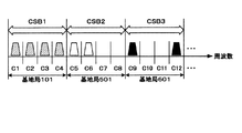
図25は、利用対象の周波数帯域において、他の無線システム11の基地局101、501、601が使用するチャネルの構成および周波数ブロック構成の例を示す説明図である。図25では、基地局101がチャネルC1,C2,C3,C4を使用し、基地局501がチャネルC5,C6,C7,C8を使用し、基地局601がチャネルC9,C10,C11,C12を使用する例を示している。
FIG. 25 is an explanatory diagram illustrating an example of a channel configuration and a frequency block configuration used by the
この場合、図25に示すように、各基地局が使用するチャネルを分けて周波数ブロック(CSB)を分割すればよい。図25に示す例では、C1〜C4を周波数ブロックCSB1とし、C5〜C8をCSB2とし、C9〜C12をCSB3として分割している。各基地局が使用するチャネル情報は、他の無線システム11において規定されるものであり、固定の場合もあるし可変の場合もある。予め他の無線システム11の規定情報を入手して周波数ブロックを分割してもよく、可変値の場合には、変更になる度に他の無線システム11の規定情報を入手して設定してもよい。情報の入手方法としては、他の無線システム11に有線または無線にて接続して入手する方法や規定値が格納されているデータベースなどにアクセスして入手する方法等が挙げられる。
In this case, as shown in FIG. 25, the frequency block (CSB) may be divided by dividing the channel used by each base station. In the example shown in FIG. 25, C1 to C4 are divided into frequency blocks CSB1, C5 to C8 are divided into CSB2, and C9 to C12 are divided into CSB3. The channel information used by each base station is defined in
本実施形態では、このようにして分割した周波数ブロックを用いて、自無線システムの端末局202にCoarseセンシングを実行させる。そして、そのCoarseセンシング結果に基づいて、基地局201は、Fineセンシング実行ノードおよびFineセンシング実行周波数ブロックを決定して他の無線システム11の周波数帯域の使用状況を推定する。
In the present embodiment, the
このとき、ノード決定しきい値情報、周波数ブロック決定しきい値情報を、周波数ブロックの分割単位とする基地局(すなわち、使用状況の推定対象とする他の無線システムの基地局)毎に設定し、Fineセンシング実行ノードおよびFineセンシング実行周波数ブロックも基地局毎に決定するものとする。 At this time, the node determination threshold information and the frequency block determination threshold information are set for each base station that is a frequency block division unit (that is, a base station of another wireless system whose usage is to be estimated). The Fine sensing execution node and the Fine sensing execution frequency block are also determined for each base station.
また、図26は、基地局101、501、601が使用するチャネルの構成および周波数ブロック構成の他の例を示す説明図である。図26では、他の無線システム11の基地局101、501、601が使用するチャネルが、連続的に配置されずに離散的に配置される例を示している。より具体的には、基地局101がチャネルC1,C4,C7,C10を使用し、基地局501がチャネルC2,C5,C8,C11を使用し、基地局601がチャネルC3,C6,C9,C12を使用する例を示している。
Moreover, FIG. 26 is explanatory drawing which shows the other example of the structure of the channel which the
この場合には、基地局毎の周波数ブロック(CSB)として、各基地局が使用する離散的なチャネルを束ねるように構成する。すなわち、図26に示す例では、チャネルC1とC4とC7とC10とを束ねて1つの周波数ブロックCSB1とし、チャネルC2とC5とC8とC11とを束ねて1つの周波数ブロックCSB2とし、チャネルC3とC6とC9とC12とを束ねて1つの周波数ブロックCSB3とすればよい。そして、このような周波数ブロック構成を用いて、Coarseセンシングを行い、Fineセンシング実行ノードおよびFineセンシング実行周波数ブロックを決定して、他の無線システム11の周波数帯域の使用状況を推定する。
In this case, as a frequency block (CSB) for each base station, it is configured to bundle discrete channels used by each base station. That is, in the example shown in FIG. 26, the channels C1, C4, C7, and C10 are bundled to form one frequency block CSB1, the channels C2, C5, C8, and C11 are bundled to form one frequency block CSB2, and the channel C3 C6, C9, and C12 may be bundled into one frequency block CSB3. Then, coarse sensing is performed using such a frequency block configuration, a Fine sensing execution node and a Fine sensing execution frequency block are determined, and the usage state of the frequency band of the
なお、端末局202では、周波数ブロックが連続的に配置されずに離散的に配置される場合であっても、該当周波数帯域のセンシング結果を1つのCoarseセンシング結果として基地局301に送信すればよい。例えば、端末局202は、該当周波数帯域分の信号を受信して、その検出信号に対して図5に示すセンシング部303のバンドパスフィルタ3033の設定を当該周波数ブロックが含む各チャネルの周波数帯域幅に設定するなどして、所望の周波数帯域幅の信号を抽出し、抽出した信号の受信信号電力値を算出してもよい。また、端末局202は、周波数ブロックが含む各チャネルごとに個別にセンシングを行い、それらのセンシング結果を合成(平均化したり加算したり)して、1つのCoarseセンシング結果にして基地局201に送信することも可能である。周波数ブロックの構成がどのようなものであれ、CoarseセンシングとFineセンシングのようにセンシング解像度を分けて行えば、センシング結果を送信するための送信時間や情報量を少なくすることができる。
Note that the
なお、上記説明では、基地局毎に周波数ブロックを分割する構成で説明したが、本実施形態はこの態様に限定されない。例えば、他の無線システム11の送信局(基地局101、501、601)の位置から自無線システム12の基地局201の位置への方位が、基準となる方位から所定の値(例えば、30度)以下となる他の無線システム11の複数の送信局により、1つの周波数ブロックを構成することも可能である。この場合、1つの周波数ブロックは、他の無線システム11の複数の基地局が使用する周波数チャネルで構成される。
In the above description, the frequency block is divided for each base station. However, the present embodiment is not limited to this mode. For example, the direction from the position of the transmitting station (
ここで、所定の方位の値は、予め自無線システム内で設定しておいてもよいし、端末局202で電波の到来方向推定を行った結果に基づいて可変の値として設定してもよい。
Here, the value of the predetermined azimuth may be set in advance within the own radio system, or may be set as a variable value based on the result of estimation of the arrival direction of the radio wave at the
以上のように、本実施形態によれば、他の無線システム11に複数の基地局が存在する場合にも、利用対象の周波数帯域が使用されているかどうかを高精度に推定することができる。
As described above, according to the present embodiment, it is possible to estimate with high accuracy whether or not the frequency band to be used is used even when there are a plurality of base stations in the
また、この推定結果に基づいて、自無線システム12において、通信または放送に使用する無線リソースの管理を適切に行なうことにより、他の無線システム11に割り当てられているまたは優先的な使用が許可されている周波数帯域を有効に利用することができる。
Further, based on this estimation result, by appropriately managing the radio resources used for communication or broadcasting in the
なお、他の無線システム11におけるチャネル情報の入手が困難で、図27に示すように、1つの周波数ブロック(CSB)内に、基地局101、501、601が使用するチャネルが存在する構成としてもよい。そのような場合には、第1の実施形態と同様に、基地局の区別なくセンシングパラメータの決定や信号検出を行えばよい。なお、そのような場合であっても、他の無線システム11のいずれかの基地局に対する受信環境のよい端末局がFineセンシング実行ノードとして選択されるため、全ての基地局に対して網羅的に周波数帯域の使用状況の推定が可能となる。
Note that it is difficult to obtain channel information in
なお、本実施形態においても、第1および第2の実施形態と同様、センシング制御部410は、Fineセンシングによる信号検出の結果に応じて、Coarseセンシングを行う周波数ブロックの構成を適応的に制御することが可能である。なお、他の点に関しても第1の実施形態や第2の実施形態と同様でよい。第1および第2の実施形態において説明した各種変形例は、本実施形態に対しても同様に適用可能である。
Also in the present embodiment, as in the first and second embodiments, the
なお、本実施形態では、他の無線システム11に複数の基地局が存在する場合について説明したが、本実施形態の方法(周波数ブロックの分割方法やしきい値の設定方法)は、複数の基地局が同一の無線システムに属している場合に限定されない。複数の基地局がそれぞれ異なる無線システムに属し、複数の他の無線システムが存在する場合にも同様に、本実施形態の方法を適用できる。
In the present embodiment, the case where a plurality of base stations exist in the
実施形態4.
次に、本発明の第4の実施形態について説明する。上記第1〜第3の実施形態では、協調センシングにCoarseセンシングとFineセンシングを行う二段階センシングを適用する場合を例に用いて説明した。しかし、本発明はCoarseセンシングとFineセンシングを行う二段階センシングを適用する場合に限定されない。そこで、本実施形態では、CoarseセンシングとFineセンシングの二段階センシング以外の協調センシングの例を示す。具体的には、本実施形態では、端末局のセンシング結果を基に、センシング実行ノードの周期を決定する。
Embodiment 4 FIG.
Next, a fourth embodiment of the present invention will be described. In the first to third embodiments, the case where two-stage sensing that performs coarse sensing and fine sensing is applied to cooperative sensing has been described as an example. However, the present invention is not limited to the application of two-stage sensing that performs coarse sensing and fine sensing. Therefore, in the present embodiment, an example of cooperative sensing other than two-stage sensing of coarse sensing and fine sensing will be described. Specifically, in this embodiment, the period of the sensing execution node is determined based on the sensing result of the terminal station.
本実施形態においても、図3に示すシステム構成図を用いて説明する。なお、本実施形態では、全ての端末局がチャネル毎にセンシングを行う場合(Fineセンシングを行う場合)において、端末局のセンシング結果を基にセンシング実行ノードの周期を決定する協調センシング手法を例に説明する。なお、センシング実行ノードの周期を決定する協調センシング手法は、全ての端末局がチャネル毎にセンシングを行う場合に限らず、どのようなセンシングに対しても適用可能である。例えば、二段階センシングを行う場合も適用可能である。 This embodiment will also be described using the system configuration diagram shown in FIG. In addition, in this embodiment, when all the terminal stations perform sensing for each channel (when performing fine sensing), a cooperative sensing method that determines the period of the sensing execution node based on the sensing result of the terminal station is taken as an example. explain. The cooperative sensing method for determining the period of the sensing execution node is not limited to the case where all the terminal stations perform sensing for each channel, and can be applied to any sensing. For example, the present invention can be applied when performing two-step sensing.
端末202の構成は、図4に示す第1の実施形態と同様でよい。すなわち、各端末局202は、基地局201から送信されるセンシング制御情報を元に、センシング(本例ではFineセンシング)を実行し、その結果を基地局201に送信する。
The configuration of the terminal 202 may be the same as that of the first embodiment shown in FIG. That is, each
図28は、本実施形態の基地局201の受信系の構成例を示すブロック図である。図28に示す基地局201は、図6に示す第1の実施形態における構成と比べて、周波数ブロック決定部408の代わりにセンシング周期決定部418を備える点、ノード決定部407の代わりにノード決定部407Bを備える点が異なる。
FIG. 28 is a block diagram illustrating a configuration example of a reception system of the
本実施形態のセンシング結果切替部404は、復調/復号部403から出力されるセンシング結果(受信信号電力値)を、センシング段階に応じて、ノード決定部407Bおよびセンシング周期決定部418、または信号検出部409に入力する。なお、当該基地局201においてもセンシングを行う場合には、センシング部406から出力されるセンシング結果も併せて出力する。本実施形態では、センシング結果切替部404は、第1のセンシング段階である場合には、センシング結果をノード決定部407Bおよびセンシング周期決定部418に入力する。一方、第2のセンシング段階である場合には、センシング結果を信号検出部409に入力する。なお、センシング周期決定部418へのセンシング結果の入力は省略可能である。すなわち、センシング周期決定部418には、ノード決定部407Bから出力される、後述のノード決定情報が入力されればよい。
The sensing
ノード決定部407Bは、ノード決定しきい値とセンシング結果である受信信号電力値とを比較し、しきい値以上となるノードとしきい値未満となるノードを決定する。また、この決定結果をノード決定情報としてセンシング制御部410とセンシング周期決定部418とに出力する。ノード決定情報は、例えば、しきい値以上となるノードの端末局IDと、しきい値未満となるノードの端末局IDとを含む情報とすることができる。
The
センシング周期決定部418は、ノード決定情報に基づいて、各端末局のセンシング周期を決定する。例えば、ノード決定しきい値以上となる端末局のセンシング周期はΔT、ノード決定しきい値未満となる端末局のセンシング周期は(2×ΔT)のように設定する。各ノードのセンシング周期は、センシング周期情報としてセンシング制御部410に出力される。
The sensing
センシング制御部410は、ノード決定部407Bから出力されるノード決定情報とセンシング周期決定部418から出力される周波数ブロック決定情報と、無線リソース管理部411から出力される無線リソース管理情報とに基づいて、センシングの制御を行う。本実施形態では、例えば、第1のセンシング段階開始時(初めてFineセンシングを始める段階)では、各Fineセンシング実行ノードに対してどの周波数ブロックをセンシングさせるかといった周波数ブロックの割当等を行い、それを指示するための制御情報を生成する。また、例えば、第2のセンシング段階開始時(2回目以降のFineセンシングを始める段階)では、引き続き各Fineセンシング実行ノードに対してどの周波数ブロックをセンシングさせるかといった周波数ブロックの割当を行うが、その際、入力されるノード決定情報とセンシング周期情報とに基づいて、各端末が決められたセンシング周期でセンシングを実行するように、それらを指示する制御情報を生成してもよい。
The
図29は、ノード決定部407Bにおけるノード決定動作の一例を示す説明図である。ここでは、端末202−1と端末202−2のセンシング結果を例に用いて説明する。図29に示す例では、端末局202−1のセンシング結果がノード決定しきい値より大きく、端末局202−2のセンシング結果はノード決定しきい値よりも低い。このような場合には、ノード決定部407Bは、端末局202−1のセンシング周期をΔT、端末局202−2のセンシング周期を(2×ΔT)と設定する。このように、センシング結果の受信信号電力値が大きな端末局は、受信環境がよいと推定されるため、センシング結果の受信信号電力値が小さな端末局よりもセンシング周期を短く設定する。
FIG. 29 is an explanatory diagram illustrating an example of a node determination operation in the
なお、上記例では、ノード決定しきい値が1つの場合で説明した。しかし、ノード決定しきい値が2つ以上の場合にも本発明の適用は可能である。 In the above example, the case where there is one node determination threshold has been described. However, the present invention can also be applied when there are two or more node determination thresholds.
図30は、ノード決定部407Bにおけるノード決定動作の他の例を示す説明図である。ノード決定しきい値を2つ(ノード決定しきい値A、ノード決定しきい値B、ノード決定しきい値A>ノード決定しきい値B)設定する場合、センシング結果と2つのノード決定しきい値との関係により、ノード決定情報を出力する。例えば、ノード決定しきい値A以上のセンシング結果を送信した端末局、ノード決定しきい値B以上で、かつノード決定しきい値A未満のセンシング結果を送信した端末局、ノード決定しきい値B未満のセンシング結果を送信した端末局、のように、複数レベルでの判定結果をノード決定情報として出力する。
FIG. 30 is an explanatory diagram illustrating another example of the node determination operation in the
このような場合であっても、センシング周期決定部418は、入力されるノード決定情報を基に、端末局のセンシング周期を決定する。上記例では、例えば、ノード決定しきい値A以上のセンシング結果を送信した端末局のセンシング周期はΔT、ノード決定しきい値B以上で、かつノード決定しきい値A未満のセンシング結果を送信した端末局のセンシング周期は(2×ΔT)、ノード決定しきい値B未満のセンシング結果を送信した端末局のセンシング周期は(3×ΔT)と設定してもよい。
Even in such a case, the sensing
なお、図30に示す例では、端末局202−1および202−2のセンシング結果をノード決定しきい値AおよびBと比較すると、端末局202−1のセンシング結果がノード決定しきい値Aより大きく、端末局202−2のセンシング結果はノード決定しきい値Bよりも低い。このような場合には、例えば、端末202−1を第1レベルのノードであると決定し、端末202ー2を第3レベルのノードであると決定し、その旨を示すノード決定情報を出力してもよい。そして、センシング周期決定部418は、そのようなノード決定情報を元に、端末局202−1のセンシング周期をΔT、端末局202−2のセンシング周期を(3×ΔT)と設定する。
In the example illustrated in FIG. 30, when the sensing results of the terminal stations 202-1 and 202-2 are compared with the node determination threshold values A and B, the sensing result of the terminal station 202-1 is greater than the node determination threshold value A. Largely, the sensing result of the terminal station 202-2 is lower than the node determination threshold B. In such a case, for example, the terminal 202-1 is determined to be a first level node, the terminal 202-2 is determined to be a third level node, and node determination information indicating that is output. May be. Then, based on such node determination information, the sensing
なお、上記説明では、センシング周期はΔT、(2×ΔT)、(3×ΔT)として説明したが、センシング周期の設定値は上記の値に限定されるものではなく、センシング周期の最小単位をΔTとして、ΔTのn倍(nは任意の正の整数)として設定することも可能である。また、センシング周期の最小単位ΔTのn倍とせずに、任意の周期として端末局毎に設定することも可能である。 In the above description, the sensing cycle is described as ΔT, (2 × ΔT), (3 × ΔT), but the setting value of the sensing cycle is not limited to the above value, and the minimum unit of the sensing cycle is ΔT can be set as n times ΔT (n is an arbitrary positive integer). Further, it is possible to set an arbitrary cycle for each terminal station without setting the minimum unit ΔT of the sensing cycle to n times.
また、本実施形態では、前のセンシング結果を元に次のセンシング実行ノードの周期を決定する例を示したが、例えば、最も低いノード決定しきい値未満のセンシング結果を送信する端末局では、センシングを行わないように決定することもできる。 Further, in the present embodiment, an example in which the period of the next sensing execution node is determined based on the previous sensing result is shown, but for example, in a terminal station that transmits a sensing result less than the lowest node determination threshold, It is also possible to decide not to perform sensing.
図31は、本実施形態における端末局202のセンシングタイミングの一例を示す説明図である。図31に示す例では、端末局202−1および202−2は、時間t1のタイミングで第1の検出動作であるFineセンシングを開始する。Fineセンシングの結果、端末局202のセンシング周期がΔT、端末局203のセンシング周期が2ΔTに決定されたとする。この場合、端末局202−1には以降のセンシングを周期ΔTで行う旨のセンシング制御信号が通知され、端末202−2には以降のセンシングを周期2ΔTで行う旨のセンシング制御信号が通知される。各端末202は、それぞれ新たな周期が決定されるまで、決定された周期にしたがって第二の検出動作であるFineセンシングを繰り返し実行する。本例の場合、端末202−1は、以降時間t2、t3、t4、t5、・・・のタイミングでFineセンシングを実行する。また、端末局202−2は、以降時間t3、t5、・・・のタイミングでFineセンシングを実行する。
FIG. 31 is an explanatory diagram showing an example of the sensing timing of the
このとき、基地局201のカバーエリア内に存在する端末局数が多い場合には、Fineセンシング実行前に、全端末局でCoarseセンシングを実行し、その結果に基づいてFineセンシング実行ノードを決定した後に、それぞれの端末局のFineセンシング実行周期を決定することも可能である。
At this time, when the number of terminal stations existing within the coverage area of the
図32にその例を示す。図32は、端末局202のセンシングタイミングの他の例を示す説明図である。図32に示すように、端末局がxからyまで数多く存在する場合には、全端末局が時間t1でCoarseセンシングを行い、そのセンシング結果を用いてFineセンシング実行ノードを決定し、決定したFineセンシングノードにFineセンシングを実行させ、そのセンシング結果を用いて、Fineセンシング実行ノードのセンシング周期を決定するようにしてもよい。本例では、時間t1の各端末でのCoarseセンシングの結果、Fineセンシング実行ノードが端末202−1と202−2に決定する。端末局202−1、202−2は、それぞれ時間t2でFineセンシングを実行し、そのセンシング結果を用いて、端末局202−1および202−2のFineセンシング周期をΔTと2ΔTに決定している。なお、基地局201の構成としては、図28に示した構成に加えて、第1の実施形態におけるノード決定部407と周波数ブロック決定部408に相当する手段を備えていればよい。なお、ノード決定部407と周波数ブロック決定部408とは必ずしも両方を備える必要はなく、チャネル数が少ない等の理由により予め決まった周波数帯域をセンシング対象とする場合や、予め決まった端末局をセンシング実行ノードとする場合などにはいずれか一方のみを備える構成も可能である。
An example is shown in FIG. FIG. 32 is an explanatory diagram showing another example of the sensing timing of the
ここで、第1の実施形態と同様に、CoarseセンシングとFineセンシングのセンシング時間とセンシング周期は、それぞれ異なる値と設定することも可能である。 Here, as in the first embodiment, the sensing time and sensing period of coarse sensing and fine sensing can be set to different values.
また、第1の実施形態と同様に、端末局202と他の無線システム11の基地局11との間の距離が所定の値より近い端末局のみがFineセンシングを実行する構成とすることも可能である。
Further, as in the first embodiment, only the terminal station whose distance between the
以上のように、本実施形態によれば、利用対象の周波数帯域が使用されているかどうかを高精度に推定することができる。また、センシングを行う端末局全体の消費電力を削減し、かつセンシング結果を送信するための無線リソースの使用量を削減することができる。 As described above, according to the present embodiment, it is possible to estimate with high accuracy whether or not the frequency band to be used is used. Further, it is possible to reduce power consumption of the entire terminal station that performs sensing, and to reduce the amount of radio resources used for transmitting the sensing result.
また、この推定結果に基づいて、自無線システム12において、通信または放送に使用する無線リソースの管理を適切に行うことにより、他の無線システム11に割り当てられているまたは優先的な使用が許可されている周波数帯域を有効に利用することができる。なお、他の点に関しては第1の実施形態や第2の実施形態や第3の実施形態と同様でよい。また、第1〜第3の実施形態において説明した各種変形例は、本実施形態に対しても同様に適用可能である。
Further, based on this estimation result, by appropriately managing the radio resources used for communication or broadcasting in the
例えば、上記説明では、端末局において受信信号電力値を算出して基地局に送信し、基地局において、しきい値と比較して使用状況を推定する例を示したが、例えば、端末局において、受信信号電力値としきい値との比較までを実行し、比較結果をセンシング結果として基地局へ送信する構成とすることも可能である。 For example, in the above description, the received signal power value is calculated and transmitted to the base station at the terminal station, and the usage situation is estimated by comparing with the threshold value at the base station. It is also possible to perform a process up to the comparison between the received signal power value and the threshold value and transmit the comparison result as a sensing result to the base station.
また、周波数帯域の使用状況推定を基地局側で行わず、端末局において行うようにしてもよい。具体的には、端末局202は、例えば、基地局201のセンシング結果切替部404と、ノード決定部407Bと、センシング周期決定部418と、信号検出部409と同等の構成を備え、利用対象の周波数帯域が他の無線システム11によって使用されているか否かの推定を行い、推定結果を基地局201に通知してもよい。このような場合には、基地局201は、センシング結果切替部404と、ノード決定部407Bと、センシング周期決定部418と、信号検出部409とを省略可能となる。なお、センシング制御部410と無線リソース管理部411は、復調/復号部403から、直接、ノード決定情報、センシング周期情報、使用状況推定結果を得ればよい。
Further, the usage status estimation of the frequency band may be performed at the terminal station without being performed at the base station side. Specifically, the
なお、この場合、端末局での判定に用いる各種しきい値(ノード決定しきい値、信号検出しきい値)は、基地局201から端末局に通知する必要がある。従って、基地局201は、各種しきい値をセンシング情報に含めて端末局に通知したり、または報知チャネルにより端末局へ通知したりする。
In this case, various threshold values (node determination threshold value, signal detection threshold value) used for determination in the terminal station need to be notified from the
上記の構成の他に、例えば、基地局201には信号検出部409を備え、端末局にはノード決定部407Bを備える構成とするなど、構築する無線システムに合わせて柔軟に、適切な構成とすることも可能である。
In addition to the above configuration, for example, the
また、基地局の代わりに、ある端末局が他の端末局のセンシング結果を収集して利用対象の周波数帯域の使用状況の推定を行う構成とすることも可能である。ここで、基地局と端末局の間に中継局が存在する場合も想定されるが、中継局は基地局に接続する端末局の一種と考えることもできるし、端末局が接続する基地局の一種と考えることもでき、中継局において利用対象の周波数帯域の使用状況の推定を行うことを排除するものではない。 Further, instead of the base station, it is also possible to adopt a configuration in which a certain terminal station collects the sensing results of other terminal stations and estimates the usage status of the frequency band to be used. Here, although it is assumed that a relay station exists between the base station and the terminal station, the relay station can be considered as a kind of terminal station connected to the base station, or the base station to which the terminal station connects. It can be considered as a kind, and does not exclude the estimation of the usage status of the frequency band to be used in the relay station.
例えば、複数の端末局間でネットワークを構成する場合には、センシング結果を基地局に送信せずに、所定の端末局(例えば、利用対象の周波数帯域の使用状況の推定を行う端末局)がセンシング制御や無線リソース管理を行い、複数の端末局間で通信または放送を行うことも可能である。この場合、所定の端末局は、センシング制御部と無線リソース管理部を備える。この場合のセンシング制御部無線リソース管理部は、図6に示すセンシング制御部410と無線リソース管理部411と同じものを採用することができる。センシング制御部と無線リソース管理部は、自または他の端末局、あるいは、基地局201から受信するノード決定情報、センシング周期情報、使用状況推定結果に基づいて、センシング制御と無線リソース管理を行えばよい。
For example, when a network is configured between a plurality of terminal stations, a predetermined terminal station (for example, a terminal station that estimates the usage status of a frequency band to be used) is transmitted without transmitting the sensing result to the base station. It is also possible to perform sensing control and radio resource management, and communicate or broadcast between a plurality of terminal stations. In this case, the predetermined terminal station includes a sensing control unit and a radio resource management unit. In this case, the same
なお、本実施形態では、他の無線システム11の基地局101からの受信信号電力を算出して利用対象の周波数帯域の使用状況の推定を行っているが、センシングのアルゴリズムは、信号電力算出アルゴリズムに限るものではない。例えば、他の無線システム11の基地局101からの受信信号電力と自無線システム12の基地局201からの受信信号電力との電力比を算出し、それを用いて利用対象の周波数帯域の使用状況の推定を行うことも可能である。
In this embodiment, the received signal power from the
また、使用状況の推定を行う対象は、他の無線システム11の基地局101として説明したが、例えば、他の無線システム11の端末局(図示せず)が送信局となる場合には、使用状況の推定を行う対象を該端末局とする構成も可能である。
In addition, although the target for estimating the use state has been described as the
また、無線リソース管理の一例として、例えば、無線リソース管理部411は、通信方式や変調方式、符号化率の管理を行うことも可能である。
As an example of radio resource management, for example, the radio
次に、本発明の概要について説明する。本発明は、複数の無線機による第1の検出動作(例えば、Coarseセンシング)の結果に基づいて、その後に行う第2の検出動作(例えば、Fineセンシング)の動作パラメータを適応的に変化させ、その動作パラメータをもってされた第2の検出動作の結果に基づいて、利用対象の周波数帯域の使用状況を推定することを特徴としている。変化させる動作パラメータの例として、第2の検出動作を行う無線機を特定するもの、第2の検出動作における検出対象の周波数の範囲や周波数の解像度、時間周期などが挙げられるが、この限りではない。 Next, the outline of the present invention will be described. The present invention adaptively changes an operation parameter of a second detection operation (for example, Fine sensing) to be performed thereafter based on a result of the first detection operation (for example, Coarse sensing) by a plurality of wireless devices, Based on the result of the second detection operation with the operation parameter, the usage status of the frequency band to be used is estimated. Examples of operating parameters to be changed include those that specify the radio device that performs the second detection operation, the frequency range of the detection target in the second detection operation, the frequency resolution, the time period, etc. Absent.
図33および図34は、本発明の概要を示すブロック図である。なお、図33は、本発明を無線システムに適用した場合の構成例を示すブロック図である。図33に示す無線システム700は、検出動作パラメータ決定手段701と、検出動作実行手段702とを備える。
33 and 34 are block diagrams showing an outline of the present invention. FIG. 33 is a block diagram showing a configuration example when the present invention is applied to a wireless system. A wireless system 700 shown in FIG. 33 includes a detection operation
検出動作パラメータ決定手段701は、他の無線システムの無線機から送信される信号を検出する検出部を備える複数の無線機からの第1の検出動作の結果に基づいて、第1の検出動作の後に行う第2の検出動作の動作パラメータを決定する。なお、検出動作パラメータ決定手段701は、上記実施形態では、例えば、ノード決定部407,407A,407Bや、周波数ブロック決定部408、第2のノード決定部416、第2の周波数ブロック決定部417、センシング周期決定部418として示されている。
The detection operation
検出動作実行手段702は、検出動作パラメータ決定手段701によって決定された動作パラメータに従って、第2の検出動作を実行する。なお、検出動作実行手段702は、上記実施形態では、センシング部303として示されている。なお、センシング303に制御指示を出すセンシング制御部410も含めて、検出動作実行手段702としてもよい。
The detection
このような構成を備えることによって、センシングによる空きチャネルの推定精度の向上と、センシングノード全体の消費電力の低減および無線リソース量の低減とを同時に充足することが可能になる。 By providing such a configuration, it is possible to simultaneously improve the estimation accuracy of an empty channel by sensing, reduce the power consumption of the entire sensing node, and reduce the amount of radio resources.
なお、検出動作パラメータ決定手段は、第2の検出動作の動作パラメータとして、第2の検出動作を行う無線機を決定してもよい。 The detection operation parameter determination unit may determine a radio device that performs the second detection operation as the operation parameter of the second detection operation.
また、検出動作パラメータ決定手段は、第2の検出動作の動作パラメータとして、第2の検出動作における検出対象の周波数の範囲、周波数の解像度、複数回繰り返し実行される第2の検出動作の時間周期または第2の検出動作の継続時間のうち少なくとも1つを決定してもよい。 In addition, the detection operation parameter determination means includes, as operation parameters of the second detection operation, a frequency range to be detected in the second detection operation, a frequency resolution, and a time period of the second detection operation that is repeatedly executed a plurality of times. Alternatively, at least one of the durations of the second detection operation may be determined.
また、検出動作実行手段は、ある2つの検出動作を一連の検出動作とし、一連の検出動作を複数回繰り返し実行してもよい。 Further, the detection operation executing means may set two detection operations as a series of detection operations, and repeatedly execute the series of detection operations a plurality of times.
また、検出動作パラメータ決定手段は、一連の検出動作における後段の検出動作である第2の検出動作の結果に基づいて、第2の検出動作の後に行う一連の検出動作における第1の検出動作の動作パラメータを決定し、検出動作実行手段は、検出動作パラメータ決定手段によって決定された動作パラメータに従って、第1の検出動作を実行してもよい。 In addition, the detection operation parameter determination unit is configured to perform the first detection operation in the series of detection operations performed after the second detection operation based on the result of the second detection operation that is the subsequent detection operation in the series of detection operations. The operation parameter may be determined, and the detection operation execution unit may execute the first detection operation according to the operation parameter determined by the detection operation parameter determination unit.
また、検出動作実行手段は、第2の検出動作を、第2の検出動作開始から経過時間が所定の値以下または第2の検出動作の結果が所定の値以上のうち少なくともいずれか1つを満足する限り継続して実行してもよい。 In addition, the detection operation execution means performs at least one of the second detection operation, the elapsed time from the start of the second detection operation being a predetermined value or less, or the result of the second detection operation being a predetermined value or more. You may continue to run as long as you are satisfied.
また、図34は、本発明を基地局や端末局といった無線機に適用した場合の構成例を示すブロック図である。図34に示す無線機801は、検出動作パラメータ決定手段701と、無線動作制御手段703と、推定手段704とを備える。なお、検出動作実行手段702は、当該無線機801を含む自無線システムの無線機のうち1つ以上の無線機が備えていればよい。図34に示す例では、当該無線機801と自無線システムの他の無線機802,803がそれぞれ検出動作実行手段702を備える例を示している。
FIG. 34 is a block diagram showing a configuration example when the present invention is applied to a radio device such as a base station or a terminal station. 34 includes a detection operation
なお、検出動作パラメータ決定手段701は、図32で示した無線システムにおける検出動作パラメータ決定手段701と同様でよい。
The detection operation
無線動作制御手段703は、検出動作パラメータ決定手段701によって決定された動作パラメータに従って、自無線システムの無線機のうちの1以上の無線機に対して第2の検出動作を行わせるための所定の制御を行う。なお、無線動作制御手段703は、上記実施形態では、例えば、センシング制御部410として示されている。
The wireless
推定手段704は、検出動作制御手段703の制御により行われた第2の検出動作の結果に基づいて、他の無線システムに割り当てられたまたは優先的な使用が許可された周波数帯域の使用状況を推定する。なお、推定手段704は、上記実施形態では、例えば、信号検出部409として示されている。
Based on the result of the second detection operation performed by the control of the detection
(付記1)さらに、本発明の無線システムにおいて、他の無線システムの送信局からの距離が所定の値よりも近い無線機が第1の検出動作を行ってもよい。 (Additional remark 1) Furthermore, in the wireless system of the present invention, a wireless device whose distance from a transmitting station of another wireless system is closer than a predetermined value may perform the first detection operation.
(付記2)また、第1の検出動作として、検出対象である複数の周波数チャネルのうち2個以上の周波数チャネルをグループ化した周波数ブロックを単位にした検出動作を行ってもよい。 (Additional remark 2) Moreover, you may perform the detection operation in the unit of the frequency block which grouped two or more frequency channels among the several frequency channels which are detection objects as 1st detection operation.
(付記3)また、周波数ブロックは、検出動作を行う地点への方位が所定の値以下となる他の無線システムの送信局で使用されている周波数チャネルを束ねたものであってもよい。 (Supplementary Note 3) Further, the frequency block may be a bundle of frequency channels used in transmitting stations of other wireless systems in which the azimuth to the point where the detection operation is performed becomes a predetermined value or less.
(付記4)また、パラメータ決定手段は、第2の検出動作の後に行う第1の検出動作のパラメータとして、第1の検出動作における検出動作単位となる周波数ブロックの構成を決定してもよい。 (Additional remark 4) Moreover, a parameter determination means may determine the structure of the frequency block used as the detection operation unit in a 1st detection operation as a parameter of the 1st detection operation performed after a 2nd detection operation.
(付記5)また、本発明の無線システムにおいて、動作パラメータの決定は、基地局で実施されてもよい。 (Additional remark 5) Moreover, in the radio | wireless system of this invention, determination of an operation parameter may be implemented in a base station.
(付記6)また、本発明の無線システムにおいて、動作パラメータの決定は、端末局で実施されてもよい。 (Additional remark 6) Moreover, in the radio | wireless system of this invention, determination of an operation parameter may be implemented in a terminal station.
(付記7)また、動作パラメータの決定が端末局で実施される場合には、動作パラメータを決定するために必要な情報を、基地局から端末局に対して送信してもよい。 (Supplementary Note 7) When the operation parameter is determined by the terminal station, information necessary for determining the operation parameter may be transmitted from the base station to the terminal station.
(付記8)また、本発明の無線機において、無線動作制御手段は、ある2つの検出動作を一連の検出動作とし、一連の検出動作を複数回繰り返し実行してもよい。 (Additional remark 8) Moreover, in the radio | wireless machine of this invention, a radio | wireless operation control means may make a certain two detection operation into a series of detection operation, and may repeatedly perform a series of detection operation in multiple times.
(付記9)さらに、本発明の無線機において、検出動作パラメータ決定手段が、一連の検出動作における後段の検出動作である第2の検出動作の結果に基づいて、第2の検出動作の後に行う一連の検出動作における第1の検出動作の動作パラメータを決定する場合には、無線動作制御手段は、検出動作パラメータ決定手段によって決定された動作パラメータに従って、第1の検出動作を行わさせるための所定の制御を行ってもよい。 (Additional remark 9) Furthermore, in the wireless device of the present invention, the detection operation parameter determination means performs after the second detection operation based on the result of the second detection operation which is the subsequent detection operation in the series of detection operations. When determining the operation parameter of the first detection operation in the series of detection operations, the wireless operation control means is a predetermined for performing the first detection operation according to the operation parameter determined by the detection operation parameter determination means. You may control.
(付記10)また、本発明のセンシング方法において、第2の検出動作の動作パラメータとして、第2の検出動作を行う無線機を決定してもよい。 (Additional remark 10) Moreover, in the sensing method of this invention, you may determine the radio | wireless machine which performs 2nd detection operation as an operation parameter of 2nd detection operation.
(付記11)また、本発明のセンシング方法において、第2の検出動作の動作パラメータとして、第2の検出動作における検出対象の周波数の範囲、周波数の解像度、複数回繰り返し実行される第2の検出動作の時間周期または第2の検出動作の継続時間のうち少なくとも1つを決定してもよい。 (Additional remark 11) Moreover, in the sensing method of this invention, as an operation parameter of 2nd detection operation | movement, the range of the frequency of the detection target in 2nd detection operation | movement, frequency resolution, 2nd detection performed repeatedly several times At least one of the time period of the operation or the duration of the second detection operation may be determined.
(付記12)また、本発明のセンシング方法において、ある2つの検出動作を一連の検出動作とし、一連の検出動作を複数回繰り返し実行してもよい。 (Additional remark 12) Moreover, in the sensing method of this invention, a certain two detection operation may be made into a series of detection operation, and a series of detection operation may be repeatedly performed in multiple times.
(付記13)また、本発明のセンシング方法において、一連の検出動作における後段の検出動作である第2の検出動作の結果に基づいて、第2の検出動作の後に行う一連の検出動作における第1の検出動作の動作パラメータを決定し、決定された動作パラメータに従って、第1の検出動作を実行してもよい。 (Additional remark 13) Moreover, in the sensing method of this invention, based on the result of the 2nd detection operation | movement which is a back | latter detection operation | movement in a series of detection operation | movement, it is the 1st in a series of detection operation | movement performed after 2nd detection operation | movement. The operation parameter of the detection operation may be determined, and the first detection operation may be performed according to the determined operation parameter.
(付記14)また、本発明のセンシング方法において、第2の検出動作を、第2の検出動作開始から経過時間が所定の値以下または第2の検出動作の結果が所定の値以上のうち少なくともいずれか1つを満足する限り継続して実行してもよい。 (Supplementary Note 14) In the sensing method of the present invention, the second detection operation may be performed at least when the elapsed time from the start of the second detection operation is a predetermined value or less or the result of the second detection operation is a predetermined value or more. As long as any one of them is satisfied, it may be executed continuously.
(付記15)また、本発明の無線機制御プログラムは、コンピュータに、第2の検出動作の動作パラメータとして、第2の検出動作を行う無線機を決定させてもよい。 (Additional remark 15) Moreover, the radio | wireless machine control program of this invention may make a computer determine the radio | wireless machine which performs 2nd detection operation as an operation parameter of 2nd detection operation.
(付記16)また、本発明の無線機制御プログラムは、コンピュータに、第2の検出動作の動作パラメータとして、第2の検出動作における検出対象の周波数の範囲、周波数の解像度、複数回繰り返し実行される第2の検出動作の時間周期または第2の検出動作の継続時間のうち少なくとも1つを決定させてもよい。 (Additional remark 16) Moreover, the radio | wireless machine control program of this invention is repeatedly performed to the computer as the operation parameter of 2nd detection operation, the range of the frequency of the detection target in 2nd detection operation, the frequency resolution, and multiple times. At least one of the time period of the second detection operation and the duration of the second detection operation may be determined.
(付記17)また、本発明の無線機制御プログラムは、コンピュータに、ある2つの検出動作を一連の検出動作とし、一連の検出動作を複数回繰り返し実行させてもよい。 (Additional remark 17) Moreover, the radio | wireless machine control program of this invention may make a computer make a certain two detection operation | movement into a series of detection operation | movement, and repeatedly perform a series of detection operation | movement several times.
(付記18)また、本発明の無線機制御プログラムは、コンピュータに、一連の検出動作における後段の検出動作である第2の検出動作の結果に基づいて、第2の検出動作の後に行う一連の検出動作における第1の検出動作の動作パラメータを決定させてもよい。 (Additional remark 18) Moreover, the radio | wireless machine control program of this invention makes a series of programs performed after a 2nd detection operation based on the result of the 2nd detection operation which is a back | latter detection operation in a series of detection operations. The operation parameter of the first detection operation in the detection operation may be determined.
(付記19)また、本発明の無線機制御プログラムは、コンピュータに、第2の検出動作を、第2の検出動作開始から経過時間が所定の値以下または第2の検出動作の結果が所定の値以上のうち少なくともいずれか1つを満足する限り継続して実行させてもよい。 (Additional remark 19) Moreover, the radio | wireless machine control program of this invention makes a computer perform 2nd detection operation, the elapsed time from the start of 2nd detection operation is less than predetermined value, or the result of 2nd detection operation is predetermined. It may be executed continuously as long as at least one of the values is satisfied.
(付記20)なお、付記1〜4に記載された事項は、本発明の無線機、センシング方法、無線機制御プログラムにも同様に適用可能である。 (Additional remark 20) In addition, the matter described in additional remarks 1-4 is applicable similarly to the radio | wireless machine of this invention, the sensing method, and a radio | wireless machine control program.
本発明は、複数の無線通信システムで周波数を共用して使用する場合に、他の無線通信システムに影響を与えずに周波数帯域を使用可能か否かを判定する用途に好適に適用可能である。 INDUSTRIAL APPLICABILITY The present invention can be suitably applied to an application for determining whether or not a frequency band can be used without affecting other wireless communication systems when using a frequency shared by a plurality of wireless communication systems. .
10 無線システム
11 他の無線システム
12 自無線システム
101,501,601 (他の無線システムの)基地局
201 (自無線システムの)基地局
202−1,202−2 端末局
301 送受信アンテナ
302 センシング・無線送受信切替部(第1のスイッチ)
303,303A センシング部
3031 直交復調部
3032 シンセサイザ部
3033 バンドパスフィルタ
3034 電力値算出部
3035 電力値判定部
304 無線送受信部
305 復調・変調切替部(第2のスイッチ)
306 復調/復号部
307 変調部
308 位置情報推定部
401 受信用アンテナ
402 無線受信部
403 復調/復号部
404,404A センシング結果切替部(スイッチ)
405 電波検出用アンテナ
406 センシング部
407,407A,407B ノード決定部
408 周波数ブロック決定部
409 信号検出部
410 センシング制御部
411 無線リソース管理部
412 制御信号生成部
413 変調部
414 無線送信部
415 送信アンテナ
416 第2のノード決定部
417 第2の周波数ブロック決定部
418 センシング周期決定部
700 無線システム
701 検出動作パラメータ決定手段
702 検出動作実行手段
703 検出動作制御手段
704 検出手段
801 無線機(自無線システムの基地局または端末局)
802,803 他の無線機
DESCRIPTION OF
303,
306 Demodulation /
405 Radio
802, 803 Other radio
Claims (10)
前記検出動作パラメータ決定手段によって決定された動作パラメータに従って、前記第2の検出動作を実行する検出動作実行手段とを備えた
ことを特徴とする無線システム。 Second detection operation performed after the first detection operation based on the result of the first detection operation from a plurality of radio devices including a detection unit that detects a signal transmitted from a radio device of another radio system Detecting operation parameter determining means for determining the operation parameter of
A radio system comprising: a detection operation execution unit that executes the second detection operation according to the operation parameter determined by the detection operation parameter determination unit.
請求項1に記載の無線システム。 The wireless system according to claim 1, wherein the detection operation parameter determination unit determines a wireless device that performs the second detection operation as an operation parameter of the second detection operation.
請求項1または請求項2に記載の無線システム。 The detection operation parameter determining means includes, as operation parameters of the second detection operation, a frequency range to be detected in the second detection operation, a frequency resolution, a time period of the second detection operation repeatedly executed a plurality of times, The wireless system according to claim 1, wherein at least one of the durations of the two detection operations is determined.
請求項1から請求項3のうちのいずれか1項に記載の無線システム。 The radio system according to any one of claims 1 to 3, wherein the detection operation execution unit sets two detection operations as a series of detection operations and repeatedly executes the series of detection operations a plurality of times.
検出動作実行手段は、前記検出動作パラメータ決定手段によって決定された動作パラメータに従って、前記第1の検出動作を実行する
請求項4に記載の無線システム。 The detection operation parameter determination unit is configured to operate the first detection operation in a series of detection operations performed after the second detection operation based on a result of the second detection operation that is a subsequent detection operation in the series of detection operations. Determine the parameters,
The wireless system according to claim 4, wherein the detection operation execution unit executes the first detection operation according to the operation parameter determined by the detection operation parameter determination unit.
請求項1から請求項5のうちのいずれか1項に記載の無線システム。 The detection operation execution means satisfies at least one of the second detection operation, the elapsed time from the start of the second detection operation being a predetermined value or less or the result of the second detection operation being a predetermined value or more. The wireless system according to any one of claims 1 to 5, wherein the wireless system is executed continuously as long as possible.
前記検出動作パラメータ決定手段によって決定された動作パラメータに従って、自無線システムの無線機のうちの1以上の無線機に対して第2の検出動作を行わせるための所定の制御を行う検出動作制御手段と、
前記検出動作制御手段の制御により行われた第2の検出動作の結果に基づいて、他の無線システムに割り当てられたまたは優先的な使用が許可された周波数帯域の使用状況を推定する推定手段とを備えた
ことを特徴とする基地局。 Second detection operation performed after the first detection operation based on the result of the first detection operation from a plurality of radio devices including a detection unit that detects a signal transmitted from a radio device of another radio system Detecting operation parameter determining means for determining the operation parameter of
Detection operation control means for performing predetermined control for causing one or more of the radio apparatuses of the own radio system to perform the second detection operation according to the operation parameter determined by the detection operation parameter determination means. When,
Estimating means for estimating a use state of a frequency band assigned to another wireless system or permitted to be used preferentially based on a result of the second detection operation performed by the control of the detection operation control means; A base station characterized by comprising:
他の無線システムの無線機から送信される信号を検出する検出部を備える複数の無線機からの第1の検出動作の結果に基づいて、前記第1の検出動作の後に行う第2の検出動作の動作パラメータを決定する検出動作パラメータ決定手段と、
前記検出動作パラメータ決定手段によって決定された動作パラメータに従って、自無線システムの無線機のうちの1以上の無線機に対して第2の検出動作を行わせるための所定の制御を行う検出動作制御手段と、
前記検出動作制御手段の制御により行われた第2の検出動作の結果に基づいて、他の無線システムに割り当てられたまたは優先的な使用が許可された周波数帯域の使用状況を推定する推定手段とを備えた
ことを特徴とする端末局。 A terminal station capable of communicating with a base station of the own radio system and another terminal station of the own radio system,
Second detection operation performed after the first detection operation based on the result of the first detection operation from a plurality of radio devices including a detection unit that detects a signal transmitted from a radio device of another radio system Detecting operation parameter determining means for determining the operation parameter of
Detection operation control means for performing predetermined control for causing one or more of the radio apparatuses of the own radio system to perform the second detection operation according to the operation parameter determined by the detection operation parameter determination means. When,
Estimating means for estimating a use state of a frequency band assigned to another wireless system or permitted to be used preferentially based on a result of the second detection operation performed by the control of the detection operation control means; A terminal station characterized by comprising:
前記決定された動作パラメータに従って、第2の検出動作を行い、
前記第2の検出動作の結果に基づいて、他の無線システムに割り当てられたまたは優先的な使用が許可された周波数帯域の使用状況を推定する
ことを特徴とするセンシング方法。 Second detection operation performed after the first detection operation based on the result of the first detection operation from a plurality of radio devices including a detection unit that detects a signal transmitted from a radio device of another radio system Determine the operating parameters of
Performing a second detection operation according to the determined operation parameter;
Based on a result of the second detection operation, a usage state of a frequency band assigned to another wireless system or permitted to be used preferentially is estimated.
他の無線システムの無線機から送信される信号を検出する検出部を備える複数の無線機からの第1の検出動作の結果に基づいて、前記第1の検出動作の後に行う第2の検出動作の動作パラメータを決定する処理、および
前記決定された動作パラメータに従って、自無線システムの無線機のうちの1以上の無線機に対して第2の検出動作を行わせるための所定の制御処理、
を実行させる無線機制御プログラム。 On the computer,
Second detection operation performed after the first detection operation based on the result of the first detection operation from a plurality of radio devices including a detection unit that detects a signal transmitted from a radio device of another radio system And a predetermined control process for causing the one or more radios of the radio system of the own radio system to perform the second detection operation according to the determined operation parameters,
Radio control program for executing
Priority Applications (1)
| Application Number | Priority Date | Filing Date | Title |
|---|---|---|---|
| JP2010034009A JP2011172019A (en) | 2010-02-18 | 2010-02-18 | Wireless system, base station, terminal station, sensing method, and wireless equipment control program |
Applications Claiming Priority (1)
| Application Number | Priority Date | Filing Date | Title |
|---|---|---|---|
| JP2010034009A JP2011172019A (en) | 2010-02-18 | 2010-02-18 | Wireless system, base station, terminal station, sensing method, and wireless equipment control program |
Publications (1)
| Publication Number | Publication Date |
|---|---|
| JP2011172019A true JP2011172019A (en) | 2011-09-01 |
Family
ID=44685672
Family Applications (1)
| Application Number | Title | Priority Date | Filing Date |
|---|---|---|---|
| JP2010034009A Pending JP2011172019A (en) | 2010-02-18 | 2010-02-18 | Wireless system, base station, terminal station, sensing method, and wireless equipment control program |
Country Status (1)
| Country | Link |
|---|---|
| JP (1) | JP2011172019A (en) |
Cited By (4)
| Publication number | Priority date | Publication date | Assignee | Title |
|---|---|---|---|---|
| JP5607789B1 (en) * | 2013-06-14 | 2014-10-15 | 日本電信電話株式会社 | Multi-band simultaneous sensing device and multi-band simultaneous sensing method |
| JP2015506604A (en) * | 2011-12-22 | 2015-03-02 | インターデイジタル パテント ホールディングス インコーポレイテッド | Method, apparatus and system for dynamic spectrum allocation |
| JPWO2013046468A1 (en) * | 2011-09-30 | 2015-03-26 | 富士通株式会社 | Wireless communication system, mobile station, base station, and wireless communication system control method |
| JP2017143579A (en) * | 2011-10-14 | 2017-08-17 | ソニー株式会社 | Electronic device, method, and computer readable medium |
-
2010
- 2010-02-18 JP JP2010034009A patent/JP2011172019A/en active Pending
Cited By (8)
| Publication number | Priority date | Publication date | Assignee | Title |
|---|---|---|---|---|
| JPWO2013046468A1 (en) * | 2011-09-30 | 2015-03-26 | 富士通株式会社 | Wireless communication system, mobile station, base station, and wireless communication system control method |
| US9408192B2 (en) | 2011-09-30 | 2016-08-02 | Fujitsu Limited | Radio communication system, mobile station, base station, and method for controlling radio communication system |
| JP2017143579A (en) * | 2011-10-14 | 2017-08-17 | ソニー株式会社 | Electronic device, method, and computer readable medium |
| US10045232B2 (en) | 2011-10-14 | 2018-08-07 | Sony Corporation | Electronic device, method and computer-readable medium for sensing spectrum usage in a cognitive radio communication system |
| JP2019118124A (en) * | 2011-10-14 | 2019-07-18 | ソニー株式会社 | Electronic device, method, and computer readable medium |
| US10700900B2 (en) | 2011-10-14 | 2020-06-30 | Sony Corporation | Electronic device, method and computer-readable medium for sensing spectrum usage in a cognitive radio communication system |
| JP2015506604A (en) * | 2011-12-22 | 2015-03-02 | インターデイジタル パテント ホールディングス インコーポレイテッド | Method, apparatus and system for dynamic spectrum allocation |
| JP5607789B1 (en) * | 2013-06-14 | 2014-10-15 | 日本電信電話株式会社 | Multi-band simultaneous sensing device and multi-band simultaneous sensing method |
Similar Documents
| Publication | Publication Date | Title |
|---|---|---|
| KR101006092B1 (en) | Seamless inter-frequency handoff in wireless communication networks | |
| US9185706B2 (en) | Anchor carrier selection in multi-carrier wireless network | |
| JP5382804B2 (en) | Wireless communication device and channel changing method thereof | |
| US20180041889A1 (en) | Wireless communication system | |
| JP5213476B2 (en) | Wireless communication method and wireless communication system | |
| US7912110B2 (en) | Base station apparatus, wireless communication system and frequency assignment method | |
| EP3314957B1 (en) | Jointly managed access point transmit power control | |
| WO2011037214A1 (en) | Base station, terminal station, radio system, radio control method, and storage medium | |
| JP4528716B2 (en) | Base station and radio communication method | |
| JP6059637B2 (en) | Wireless communication system, wireless communication terminal, system base station, wireless LAN base station | |
| US20150223259A1 (en) | Communication control apparatus, communication control method, and communication system | |
| KR20090086982A (en) | Base station apparatus, user equipment and method used in mobile communication system performing inter-band handover | |
| US8731571B2 (en) | Radio base station device and radio resource connection switching method | |
| JP2011172019A (en) | Wireless system, base station, terminal station, sensing method, and wireless equipment control program | |
| US20140162715A1 (en) | Channel information providing method, channel information providing database server, and channel information providing system | |
| KR20220054302A (en) | Multiple Simultaneous Bandwidth Portions for Cellular Network Base Stations | |
| JP5313111B2 (en) | Wireless communication system | |
| JP6103701B2 (en) | Wireless communication system, centralized control station, and wireless communication method | |
| JP5795666B1 (en) | Wireless communication system, wireless communication control method, wireless base station control device, and computer program | |
| JP6689934B2 (en) | Base station, wireless communication method, and wireless communication system | |
| JP2011071569A (en) | Radio communication system | |
| JP5159806B2 (en) | Communication method and communication terminal | |
| JP5164746B2 (en) | Wireless communication method and wireless communication base station | |
| JP4767771B2 (en) | Base station apparatus and spatial multiplexing method | |
| JP5697092B2 (en) | Reception discrimination system |