JP2011159180A - Display control apparatus, display control method, program and storage medium - Google Patents
Display control apparatus, display control method, program and storage medium Download PDFInfo
- Publication number
- JP2011159180A JP2011159180A JP2010021589A JP2010021589A JP2011159180A JP 2011159180 A JP2011159180 A JP 2011159180A JP 2010021589 A JP2010021589 A JP 2010021589A JP 2010021589 A JP2010021589 A JP 2010021589A JP 2011159180 A JP2011159180 A JP 2011159180A
- Authority
- JP
- Japan
- Prior art keywords
- button
- display
- display control
- contact input
- input
- Prior art date
- Legal status (The legal status is an assumption and is not a legal conclusion. Google has not performed a legal analysis and makes no representation as to the accuracy of the status listed.)
- Pending
Links
Images


Abstract
Description
本発明は、接触入力を検出可能な表示装置の表示制御技術に関する。 The present invention relates to a display control technique for a display device capable of detecting contact input.
近年、デジタルカメラ等の撮像装置において、タッチパネルディスプレイのような、表示領域上への接触入力を検出可能な表示装置を備えるものが知られている。このような撮像装置では、表示装置の表示領域上に接触入力によって操作可能なGUIのボタン等を表示することにより、撮像装置に設ける物理的な操作部材を減らすことができるため、生産コストを抑えることが可能である。また、表示領域上に接触可能なGUIのボタンを用いる場合、ユーザの操作性の好みに合わせて、表示領域上でGUIを所望の表示位置に移動させることが可能である。 2. Description of the Related Art In recent years, there has been known an imaging apparatus such as a digital camera that includes a display device that can detect a touch input on a display area, such as a touch panel display. In such an imaging apparatus, by displaying a GUI button or the like that can be operated by contact input on the display area of the display apparatus, the number of physical operation members provided in the imaging apparatus can be reduced, thereby reducing production costs. It is possible. When a GUI button that can be touched on the display area is used, it is possible to move the GUI to a desired display position on the display area in accordance with the user's operability preference.
接触入力によって操作可能なGUIを表示する技術は携帯電話のような端末でも利用可能である。特許文献1では、GUIのボタンを接触入力によるドラッグ操作で移動させる場合に、ボタン自体ではなく、ボタンに代わるオブジェクトを移動して、移動位置を決定した後にボタンを移動する手法が開示されている。
A technique for displaying a GUI that can be operated by contact input can also be used in a terminal such as a mobile phone.
しかしながら、特許文献1のような方法でGUIのボタン等の表示位置を移動する場合、ユーザは移動が完了するまで選択されたボタンがいずれであるか判断できず、選択を誤った場合に操作を途中で意図的に中断することが難しかった。また、移動対象のGUIとは異なる表示を移動するため、操作が直感的ではなかった。
However, when the display position of a GUI button or the like is moved by a method such as
また、接触入力によって操作可能なGUIのボタンをユーザに操作させる場合、表示領域の大きさによっては、個々のボタンの表示サイズを小さくする必要がある。このような場合、ユーザが指でボタンを選択しようとすると、ボタンの表示を覆ってしまい、ボタンを視認することが難しく、ユーザは選択されたボタンを認識できないことがあった。
本発明は、上述の問題点に鑑みてなされたものであり、移動対象のGUIの視認性を確保して直感的に操作可能にすることを目的とする。
Also, when the user operates a GUI button that can be operated by contact input, the display size of each button needs to be reduced depending on the size of the display area. In such a case, when the user tries to select a button with a finger, the display of the button is covered, it is difficult to visually recognize the button, and the user may not be able to recognize the selected button.
The present invention has been made in view of the above-described problems, and it is an object of the present invention to ensure the visibility of a GUI to be moved and make it intuitively operable.
前述の目的を達成するために、本発明の表示制御装置は、以下の構成を備える。
接触入力を検出可能な表示装置の表示を制御する表示制御手段と、表示装置の表示領域上に表示された、表示位置が変更可能なボタンに、接触入力がなされたか否かを判定する第1の判定手段と、を備え、表示制御手段は、第1の判定手段でボタンに接触入力がなされたと判定された場合、該ボタンを、該ボタンの表示位置とは異なる他の表示位置に移動して表示させ、表示位置には何も表示させないように制御することを特徴とする。
In order to achieve the above object, a display control apparatus of the present invention comprises the following arrangement.
A display control unit that controls display of a display device capable of detecting contact input, and a first that determines whether or not contact input has been made to a button that is displayed on a display area of the display device and whose display position can be changed. The display control means moves the button to another display position different from the display position of the button when the first determination means determines that the touch input is made to the button. The display is controlled so that nothing is displayed at the display position.
このような構成により本発明によれば、移動対象のGUIの視認性を確保して直感的に操作することを可能とする。 With such a configuration, according to the present invention, the visibility of the GUI to be moved can be ensured and intuitive operation can be performed.
以下、本発明の好適な一実施形態について、図面を参照して詳細に説明する。なお、以下に説明する一実施形態は、表示制御装置の一例としての、タッチパネル式ディスプレイを備え、ユーザからの表示装置上への接触入力を検出可能なデジタルカメラに、本発明を適用した例を説明する。しかし、本発明は、接触入力を検出することが可能な任意の表示装置に接続し、表示装置の表示を制御可能な任意の機器に適用可能である。 Hereinafter, a preferred embodiment of the present invention will be described in detail with reference to the drawings. In addition, one embodiment described below is an example in which the present invention is applied to a digital camera that includes a touch panel display as an example of a display control device and can detect a contact input from a user onto the display device. explain. However, the present invention can be applied to any device that can be connected to an arbitrary display device capable of detecting a contact input and can control the display of the display device.
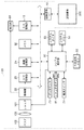
図1は、本発明の実施形態に係るデジタルカメラの機能構成を示すブロック図である。
システム制御部50は、例えばCPUであり、デジタルカメラ100が備える各ブロックの動作を制御する。システム制御部50は、例えば後述する不揮発性メモリ56に記憶されている、デジタルカメラ100の各ブロックの動作プログラムを読み込み、システムメモリ52に展開して実行することにより、各ブロックの動作を制御可能である。不揮発性メモリ56は、書き換え可能な記憶領域であり、デジタルカメラ100の各ブロックの動作プログラムに加え、デジタルカメラ100の各ブロックの動作に必要な各種パラメータ、表示部28に表示させるGUIデータ等を記憶する。なお、本実施形態では、デジタルカメラ100の動作における複数のモードのそれぞれについて、表示部28に表示させるGUIボタンの表示領域における配置(表示位置)情報が、GUIボタン管理テーブルとして、不揮発性メモリ56に記憶されている。GUIボタン管理テーブルには、それぞれのモードで表示されるボタンの種類(組み合わせ)、ボタンの配置位置及びボタン表示領域の座標情報等が記憶されている。システムメモリ52は、プログラムの展開等に用いられる、書き換え可能な一時的な記憶領域であり、デジタルカメラ100の動作の過程において必要な、種々のパラメータ等が保持可能である。
FIG. 1 is a block diagram showing a functional configuration of a digital camera according to an embodiment of the present invention.
The
撮像部22は、CCDやCMOSセンサ等の撮像素子であり、シャッタ101が所定の時間開いた際に、撮像レンズ等の光学系103を介して撮像部22に結像された光学像を光電変換し、得られたアナログ画像信号を出力する。バリア102は、光学系103の汚れや破損を防止するために装着されたものであり、デジタルカメラ100の基本的な撮像動作には関与しないものとする。A/D変換部23は、撮像部22から出力されたアナログ画像信号に対し、A/D変換処理を適用することにより得られたデジタル画像データを、画像処理部24またはメモリ32に出力する。なお、撮像の指示は、ユーザによってシャッタボタン61が操作されたときに行われる。シャッタボタン61は、半押し状態にされた際にSW1信号を出力し、全押し状態にされた際にSW2信号を出力する。システム制御部50は、SW1信号を受信すると被写体に合焦等、被写体の撮像に適した状態に各ブロックを制御し、SW2信号を受信すると記録用の撮像を行うものとする。
The
画像処理部24は、入力されたデータに対し、所定の画素補間や拡大縮小等のリサイズ処理、及び色調変換処理等を適用し、得られた画像データをメモリ32に出力する。また、画像処理部24は、入力されたデジタル画像データを用いて所定の演算処理を行い、得られた演算結果をシステム制御部50に伝送する。システム制御部50は、入力された演算結果に基づいて露光、及び測距制御を行い、TTL(スルー・ザ・レンズ)方式のAF(オートフォーカス)処理、AE(自動露出)処理、AWB(オートホワイトバランス)処理等を行う。
The
メモリ32は、デジタルカメラ100が備える内蔵メモリであり、後述する記録媒体200への画像データの記録の際の一時的な記憶領域であり、A/D変換部23及び画像処理部24から出力された画像データを記憶する。メモリ32は、所定枚数の静止画像等を記憶可能な記憶容量を備え、記録媒体200がデジタルカメラ100に装着されていない場合等のデータの保存領域としても用いることができる。また、メモリ32は後述する表示部28に表示する画像データの展開を行う、ビデオメモリとしての領域を兼ねており、撮像されたデジタル画像データや記録媒体200から読み込んだ画像データ等が展開した後、D/A変換部13に出力する。なお、表示部28にGUIデータを表示する場合にも、メモリ32のビデオメモリにおいて画像合成処理が行われる。
The
D/A変換部13は、表示部28に画像を表示するために、メモリ32から入力されたデジタル画像データに対してD/A変換処理を適用し、得られたアナログ画像信号を表示部28に出力する。記録媒体I/F18はデジタルカメラ100が備えるメモリカードスロット等の、記録媒体200との通信を行うためのインタフェースであり、記録媒体I/F18を介すことで、記録媒体200の着脱の検出やデータの読み書きを可能とする。記録媒体200は、デジタルカメラ100に着脱可能に接続される、例えばメモリカードやHDD等の外部記録装置であり、本実施形態ではデジタルカメラ100で撮像された画像や動画像が記録されるものとする。
The D /
表示部28は、デジタルカメラ100に内蔵されたLCD等の表示装置であり、入力されたアナログ画像信号を表示装置の表示領域に表示する。表示部28は、撮像部22から出力されたアナログ画像信号をスルー表示することにより、電子ビューファインダとして機能し、ユーザに対し記録可能な画像を提示可能である。なお、スルー表示とともにGUIデータを表示する場合は、撮像部22から出力されたアナログ画像信号はデジタル画像データに変換され、メモリ32でGUIデータを重畳表示するように合成処理が適用された後、D/A変換部13から表示部28に表示される。なお、本実施形態のデジタルカメラ100は、表示部28の表示領域上にタッチセンサ70を有し、タッチパネル式ディスプレイとして機能するものとする。具体的には、タッチセンサ70は、ユーザの指やペン等のデバイスによって表示部28上のタッチセンサ70に対して接触入力がなされた場合、例えば接触入力がなされた点を、表示領域上の座標に変換してシステム制御部50に出力する。
The
またシステム制御部50は、タッチセンサ70からの出力信号に基づき、タッチパネルディスプレイ上に対する以下の状態(操作)を認識できる。
タッチダウン:接触入力が無かった状態から新たに接触入力があったこと
タッチオン :接触入力を認識している状態
ムーブ :タッチオンされ、かつ接触したまま入力点が移動していること(ドラッグ等)
タッチアップ:接触入力されていた入力点が所定時間以上認識されず、入力が消失したと判断された瞬間と消失位置座標
フリック :所定速度以上のムーブ直後にタッチアップされたこと(指ではじく等)
タッチオフ :接触入力がなされていない状態
なお、上述の6つの状態認識を用いて、本実施形態のGUIタッチ操作処理について以下に説明するが、状態の名称、及び各処理のトリガーとなる状態の指定は一例を示すものであり、以下に限定されない。
Further, the
Touchdown: New contact input from no contact input Touch-on: Recognized contact input Move: Touch-on and input point moving while touching (drag, etc.)
Touch-up: Input point that has been touched is not recognized for more than a predetermined time, and the moment when it is determined that the input has disappeared and the coordinates of the disappearing position Flick: Touch-up immediately after the move at a predetermined speed or more (flicking with a finger, etc.) )
Touch-off: state in which contact input is not made Note that the GUI touch operation processing of this embodiment will be described below using the above-described six state recognitions, but the designation of the state name and the state that triggers each processing Is an example and is not limited to the following.
このような構成をもつ本実施形態のデジタルカメラ100の、GUIタッチ操作処理について、図2のフローチャートをさらに用いて説明する。なお、本GUIタッチ操作処理は、デジタルカメラ100が起動され、システム制御部50が起動時に行われる所定の処理を実行した後、表示部28に撮像された画像がスルー表示された後に開始されるものとする。しかしながら、本発明の実施はデジタルカメラ100が撮像のために動作している状態に限らず、例えば記録媒体200に記録されている画像を閲覧するために動作している状態であっても適用可能である。
The GUI touch operation processing of the
S201で、システム制御部50は、現在のデジタルカメラ100に設定されているモードを判定し、モードにおいて設定されている、表示部28に表示する機能が割り当てられたGUIのボタンの組み合わせを読み込む。具体的には、システム制御部50はシステムメモリ52に記憶されているGUIボタン管理テーブルを参照し、現在のデジタルカメラ100のモードで表示するボタン及びその表示位置の情報を取得する。そしてシステム制御部50は、表示するボタンのGUIデータをメモリ32に伝送し、表示部28に表示する撮像された画像データに対し重畳させ、画像データをD/A変換部13に出力してD/A変換処理を適用後、表示部28に出力させる。これにより、表示部28には撮像されている被写体像のスルー表示に加え、GUIのボタンが重畳表示される。
In step S <b> 201, the
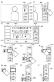
本実施形態のデジタルカメラ100には、例えばオート撮像モードやマニュアル撮像モード、及び閲覧モード等の複数のモードが用意されており、それぞれのモードにおいて実行可能な機能を有するボタンが異なる。例えばデジタルカメラ100がオート撮像モードであった場合、表示部28の表示領域には図4(a)のように、GUIボタン群とその表示枠400が表示される。GUIボタン群には、例えば撮影モード設定ボタン401、ストロボ設定ボタン402、セルフタイマ設定ボタン403、機能設定ボタン404、表示切り替えボタン405が含まれる。ユーザは、これらのボタンを接触入力によって選択することにより、各種のボタンに割り当てられた機能を実行可能である。
The
S202で、システム制御部50は、現在の接触入力の状態(操作)を検出する。具体的には、タッチセンサ70から接触入力がなされた表示領域上の座標情報を受信した場合は、システムメモリ52に受信した座標情報を記憶する。さらに、システム制御部50は、システムメモリ52に記憶されている接触入力がなされた表示領域上の座標情報の履歴情報を参照することにより、現在なされている接触入力の操作を判別する。
In S202, the
接触入力の操作がタッチダウン操作であった場合、システム制御部50は処理をS204に移す(S203)。S204で、システム制御部50は、不揮発性メモリ56に記憶されているGUIボタン管理テーブルを参照し、現在の接触入力の座標情報がボタンの表示領域に含まれるか否かを判断する。システム制御部50は、ボタンの表示領域に接触入力がなされたと判断した場合は処理をS205に移し、ボタンの表示領域以外に接触入力がなされたと判断した場合は処理をS202に戻す。
If the touch input operation is a touch-down operation, the
S205で、システム制御部50は、メモリ32において撮像された画像データに重畳するGUIのボタンのうち、S204で接触入力がなされたと判断されたボタンの表示をハイライト表示させて重畳させる。このとき、システム制御部50は、接触入力がなされたと判断されたボタンの情報を、例えば選択されているボタンの情報としてシステムメモリ52に記憶する。そしてシステム制御部50は、合成された画像データを、D/A変換部13でD/A変換処理を適用させた後、表示部28に表示させる。これにより、ユーザに対して選択されたボタンを識別可能に提示することが可能である。図4(b)では、ユーザによって表示部28の表示領域上に描画されているGUIボタン群のうち、ストロボ設定ボタン402が選択され、ハイライト表示された例を表している。そしてS206で、システム制御部50は、現在選択されたボタンに対して、所定時間経過後にイベントを発生させるためのタイマを、システムタイマ53に設定した後、処理をS202に戻す。
In S205, the
接触入力の操作がムーブ操作であった場合、システム制御部50は処理をS208に移す(S207)。S208で、システム制御部50は、不揮発性メモリ56に記憶されているGUIボタン管理テーブルを参照し、現在の接触入力の座標情報がボタンの表示領域に含まれるか否かを判断する。システム制御部50はボタンの表示領域に接触入力がなされたと判断した場合は処理をS210に移し、ボタンの表示領域以外に接触入力がなされたと判断した場合は処理をS209に移す。
If the touch input operation is a move operation, the
S209で、システム制御部50はシステムメモリ52に記憶されている、選択されているボタンの情報を参照し、選択されているボタンが存在する場合は、メモリ32にハイライト表示させているボタンを、通常の表示方法に切り替えて合成させる。そしてシステム制御部50は、合成された画像データを、D/A変換部13でD/A変換処理を適用させた後、表示部28に表示させる。
In step S209, the
S208でボタンの表示領域に接触入力がなされたと判断した場合、システム制御部50は不揮発性メモリ56に記憶されているGUIボタン管理テーブルを参照し、現在の接触入力の座標情報に存在するボタンの情報を取得する。さらにシステム制御部50は、システムメモリ52に記憶されている選択されているボタンの情報を参照し、現在接触入力がなされたと判断されたボタンと、選択されているボタンが同一であるかを判断する(S210)。即ち、システム制御部50は、ムーブ操作によって、選択されているボタンに変更がないかを判断する。システム制御部50は、選択されているボタンが同一であると判断した場合は処理を後述するS212に移し、選択されているボタンが異なると判断した場合は処理をS205に移す。なお、システムメモリ52に選択されているボタンの情報が存在しない場合、システム制御部50は処理をS205に移す。またシステム制御部50は、S205で新たにハイライト表示を切り替え、S206でタイマ設定を行えばよい。
If it is determined in S208 that a touch input has been made in the button display area, the
接触入力の操作がタッチオン操作であった場合、システム制御部50は処理をS212に移す(S211)。S212で、システム制御部50はシステムタイマ53から、所定時間経過して発生するイベントによる割り込み処理が存在するかを判断する。システム制御部50は、割り込み処理が存在する場合は処理をS213に移し、割り込み処理が発生していない場合は処理をS202に戻す。
If the touch input operation is a touch-on operation, the
S213でシステム制御部50は、ユーザに対して、タッチアップ操作を行うとボタンの位置が変更可能なことを説明するガイダンスのGUIデータを不揮発性メモリ56から取得し、メモリ32に伝送して重畳表示するように合成させて、表示部28に表示させる。即ち、システム制御部50は、GUIボタン群のうち、一つのボタンが選択された状態で、接触入力がなされたまま一定時間経過すると、タッチアップ操作を検出してボタン位置を変更する処理に移行可能な状態となる。そしてシステム制御部50は処理をS202に戻す。
In step S <b> 213, the
接触入力の操作がタッチアップ操作であった場合、システム制御部50は処理をS215に移す(S214)。S215でシステム制御部50は、表示部28にタッチアップ操作を行うとボタンの位置が変更可能なことを説明するガイダンスのGUIデータを重畳表示させているか否かを判断する。システム制御部50は、ガイダンスが表示されていない場合は、システムメモリ52に選択されているボタンの情報を参照する。そして、選択されているボタンの情報が存在する場合は、表示部28に所定の時間、選択されているボタンの機能の説明表示を重畳表示させた後、処理をS216に移し、ボタンに割り当てられた処理を実行する。例えば、図4(b)のようにストロボ設定ボタンが選択されている場合は、撮影時のストロボの挙動を、自動発光、発光禁止、赤目発光、強制発光からユーザに選択させることが可能である。そしてシステム制御部50は処理をS201に戻す。なお、選択されているボタンの情報が存在しない場合は、S216の処理は行わない。
If the touch input operation is a touch-up operation, the
S215でタッチアップ操作を行うとボタンの位置が変更可能なことを説明するガイダンスが表示されている場合、システム制御部50はメモリ32にボタン位置変更可能通知のGUIの合成を停止させ、処理をS217に移す。そしてシステム制御部50は、ユーザに対してGUIボタン群の表示位置を変更させるGUI位置変更処理を実行する。
If the guidance explaining that the button position can be changed when the touch-up operation is performed in S215 is displayed, the
ここで、図3のフローチャートを用いてGUI位置変更処理についてさらに説明する。
S301で、システム制御部50は、不揮発性メモリ56からボタンの表示位置が変更可能な状態であることを表す変更可能通知を取得してメモリ32に伝送し、表示部28において、撮像された画像データに重畳表示されるように合成させる。そしてシステム制御部50は、合成された画像データに対してD/A変換部13でD/A変換処理を適用させ、表示部28の表示領域上に表示させる。このときシステム制御部50は、デジタルカメラ100が有する複数のモードで表示される全てのGUIのボタン、及びボタンが配置可能として定められた所定の表示位置を示す枠も重畳表示させる。
Here, the GUI position changing process will be further described with reference to the flowchart of FIG.
In step S <b> 301, the
図4(c)は、S301で表示部28に表示されるボタンを含むGUIデータを表す。図4(c)において、表示部28にはオート撮像モードで表示されるGUIボタン群及び表示枠400に加え、オート撮像モードでは表示されない露出補正設定ボタン411、表示領域左側の表示枠410、及びボタンの表示位置の変更可能通知420が表示される。このように、全てのモードにおいて表示されるGUIのボタンを、ボタンの表示位置を変更する際にも表示、及び変更可能とすることにより、全てのモードにおいて、同じ機能をもつボタンを、同じ表示位置に表示させることが可能となる。表示枠400及び410はボタンが配置可能のして定められた表示位置を示しており、本実施形態では、ユーザは表示位置を変更したボタンを、表示枠400及び410のいずれかの枠に配置可能である。また、ボタンの表示位置の変更可能通知420には、ボタン表示位置のプリセットパターンから選択することが可能であるプリセット選択ボタン421、及びボタンの表示位置が変更可能な状態を終了するための終了ボタン422が含まれている。
FIG. 4C shows GUI data including buttons displayed on the
S302で、システム制御部50は、現在の接触入力の状態(操作)を検出する。具体的には、タッチセンサ70から接触入力がなされた表示領域上の座標情報を受信した場合は、システムメモリ52に受信した座標情報を記憶する。さらに、システム制御部50は、システムメモリ52に記憶されている接触入力がなされた表示領域上の座標情報の履歴情報を参照することにより、現在なされている接触入力の操作を判別する。
In S302, the
接触入力の操作がタッチダウン操作であった場合、システム制御部50は処理をS304に移す(S303)。S304で、システム制御部50は、不揮発性メモリ56に記憶されているGUIボタン管理テーブルを参照し、現在の接触入力の座標情報がボタンの表示領域に含まれるか否かを判断する(第1の判定)。システム制御部50は、ボタンの表示領域に接触入力がなされたと判断した場合は処理をS305に移し、ボタンの表示領域以外に接触入力がなされたと判断した場合は処理をS308に移す。
If the touch input operation is a touchdown operation, the
S305で、システム制御部50は、接触入力がなされたと判断されたボタンの情報を、例えば選択されているボタンの情報としてシステムメモリ52に記憶するとともに、当該ボタンの移動フラグをONにしてシステムメモリ52に記憶する。このときシステム制御部50は、表示部28に重畳表示させているボタンの表示位置の変更可能通知の表示を中止するために、メモリ32において変更可能通知のGUIデータの合成を中止させる。
In S305, the
S306で、システム制御部50は、表示部28において、選択されたボタンが選択された際に配置されていた表示枠とは異なる、他の表示位置に表示されるよう、メモリ32に選択されたボタンのGUIを合成させる。このとき、システム制御部50は、メモリ32において合成する、選択されたボタンに対して色を変更してもよい(ハイライト表示)。例えば、図4(d)のように、表示されている表示位置が変更可能なボタン群の中から、表示枠400に表示されていたストロボ設定ボタンを選択した場合、選択されたボタンは表示枠400から突出した430に表示される。このとき、ストロボ設定ボタンが表示されていた、表示枠400の領域にはボタンは表示されず、空白領域となる。これによりユーザに対して、選択されたボタンがユーザの指などで視認できなくなることなく、選択されて移動状態となったということを認識させることが可能である。
In S <b> 306, the
S307で、システム制御部50は、現在移動フラグがONに設定されているボタンが、現在表示されている位置でタッチアップされた際に格納される表示枠上の格納領域を、表示枠に対して識別可能に表示する(格納位置表示処理)。具体的には、システム制御部50は、現在移動フラグがONに設定されているボタンの表示位置を参照し、格納位置を算出することにより、表示枠上のどの格納領域にボタンが格納されて表示されるかを判断する。例えば図5のように、表示部28に、ボタンを配置可能な表示枠の中の領域が10箇所存在する場合、それぞれの格納領域に対して、表示領域を左右に2分割、上下に5分割した判定領域が割り当てられる。そして、ユーザの操作によって、移動フラグがONに設定されているボタンが(例えばボタンの中心座標が)、どの判定領域に存在するかを判定して格納領域を決定する。このようにして決定された表示枠上の格納領域は、例えば図4(d)のように、格納候補枠431が表示枠400に重畳表示されることにより識別可能とすればよい。そして、システム制御部50は格納位置を表示した後、処理をS302に戻す。
In step S <b> 307, the
S308で、システム制御部50は、ボタンの表示位置の変更可能通知420上のプリセット選択ボタン421が選択されたか否かを判断する。具体的には、システム制御部50は、接触入力がなされた座標がプリセット選択ボタン421の表示領域内である場合、プリセット選択ボタン421が選択されたと判断する。プリセット選択ボタン421が選択された場合は、システム制御部50は表示位置の変更可能通知420の表示を中止し、S309で表示部28に予め設定されているボタンの表示位置のパターンを複数表示し、ユーザに対して選択させる。予め設定されているボタンの表示位置のパターンは、例えば不揮発性メモリ56に記憶されており、GUIの形で表示部28に重畳表示されて構わない。ユーザによってボタンの表示位置のパターンが選択された後、システム制御部50はボタンの表示位置を、選択されたパターンの表示位置に変更し、処理をS301に戻す。
In S308, the
S308でプリセット選択ボタン421が選択されていない場合、システム制御部50は、ボタンの表示位置の変更可能通知420上の終了ボタン422が選択されたか否かを判断する(S310)。具体的には、システム制御部50は、接触入力がなされた座標が終了ボタン422の表示領域内である場合、終了ボタン422が選択されたと判断する。システム制御部50は、終了ボタン422が選択されたと判断された場合はGUI位置変更処理を完了し、選択されていないと判断された場合は処理をS302に戻す。
When the
接触入力の操作がムーブ操作であり、かつシステムメモリ52に記憶されている、選択されているボタンの移動フラグがONである場合、システム制御部50は処理をS312に移す(第2の判定、S311)。S312で、システム制御部50はムーブ操作の移動量が、ボタンを移動すると判定する移動量以上であるか否かを判断する。具体的には、システム制御部50は、システムメモリ52に記憶されている接触入力がなされた座標の履歴情報から、ムーブ操作の開始座標から、現在接触入力がなされている座標までの移動量を算出する。そしてシステム制御部50は、例えば不揮発性メモリ56に記憶されているボタンを移動すると判定する移動量の情報より、算出されたムーブ操作の移動量が大きい場合、ボタンの表示位置を移動すると判定し、処理をS313に移す。また、ムーブ操作の移動量が、ボタンを移動すると判定する移動量より小さい場合、処理をS302に戻す。
If the contact input operation is a move operation and the movement flag of the selected button stored in the
S313で、システム制御部50は、タッチセンサ70から取得した、現在接触入力がなされている座標に追従させて、ボタンの表示位置を移動する。またS314で、システム制御部50は格納位置表示処理を行い、現在のボタンの表示位置でタッチアップ操作がなされたときに、格納される表示枠の格納領域に、格納候補枠が重畳表示される。
In step S <b> 313, the
本実施形態では、検出されたムーブ操作において、表示領域の垂直方向の移動量が存在する場合、表示位置を移動するボタンは表示枠に沿って、対応する垂直方向の移動量分移動するものとする。図4(e)では、選択された表示位置を移動するボタンである、突出したストロボ設定ボタン430は、ボタンの表示枠400に隣接した状態で、ムーブ操作の垂直移動量の分だけ移動して表示される。そして、ストロボ設定ボタン430の表示位置に合わせて、格納候補枠431が、表示枠400上に重畳表示されている。このようにすることで、垂直方向に表示された表示枠内のGUIボタン群の中でボタンの表示位置を変更する場合、表示枠の横に移動するボタンが表示されるため、ユーザは直感的に格納される表示枠の格納領域を認識することが可能である。
In the present embodiment, in the detected move operation, when there is a vertical movement amount of the display area, the button for moving the display position moves along the display frame by the corresponding vertical movement amount. To do. In FIG. 4E, the protruding
また、表示枠400から突出したストロボ設定ボタン430を、表示枠410上の格納領域に移動させる場合は、例えば次のように操作すればよい。図4(f)のように、ムーブ操作で、接触入力がなされている点がストロボ設定ボタン430の表示領域の、例えば中央に設定された所定の領域に移動した場合、図4(g)のように、ユーザがボタン上に指を接触させたままボタンを移動させることが可能になる。このように操作することで、ユーザは表示枠400に格納されていたボタンを、表示枠410にも格納させることが可能である。
Further, when the
接触入力の操作がタッチアップ操作であり、かつシステムメモリ52に記憶されている、選択されているボタンの移動フラグがONである場合、システム制御部50は処理をS316に移す(S315)。S316で、システム制御部50は移動フラグがONに設定されているボタンの表示位置を参照し、格納位置を算出して、格納位置に隣接する位置に選択されているボタンを移動させて表示部28に表示させる。そしてS317で、システム制御部50は格納位置にボタンを格納させて表示させる。このとき、格納位置として設定された表示枠の格納領域に、別のボタンが表示されていた場合、システム制御部50は次のように処理する。システム制御部50は、選択されているボタンを格納位置に格納するとともに、格納領域に格納されていた別のボタンを、選択されているボタンが格納されていた領域に移動して格納する。
When the contact input operation is a touch-up operation and the movement flag of the selected button stored in the
即ち、タッチアップ操作が検出された際に、表示位置を移動するストロボ設定ボタン430は、図4(h)のように格納される格納領域に隣接する位置に移動する。そして、図4(i)のようにストロボ設定ボタン430が格納領域に格納されるとともに、格納領域に表示されていた表示切り替えボタン432は、ストロボ設定ボタン430が移動される前に格納されていた格納領域に格納される。図のように、それぞれのボタンが入れ替えられて格納される過程を描画することにより、入れ替わったボタン及び、移動したボタンをユーザに認識させることが可能である。
That is, when a touch-up operation is detected, the
このように処理を実行した後、システム制御部50は処理をS301に戻して、ボタンの表示位置の変更可能通知のGUIデータを表示部28に表示させる。なお、検出された接触入力の操作が、タッチダウン、ムーブ、及びタッチアップのいずれでもない場合は、システム制御部50は処理をS302に戻す。
After executing the process in this manner, the
なお、本実施形態において、ボタンの表示位置を変更するために、表示領域を突出したボタンを移動するための操作を、図を用いて例示したが、移動のための操作、及びボタン格納時の動作については上記に限定せず、種々の変形が可能である。 In this embodiment, in order to change the display position of the button, the operation for moving the button protruding from the display area is illustrated by using the drawing, but the operation for moving and storing the button are illustrated. The operation is not limited to the above, and various modifications are possible.
以上説明したように、本実施形態の表示制御装置は、表示装置に表示された、表示位置が変更可能なボタンに接触入力がなされた際に、ボタンの表示されている位置とは異なる他の表示位置に移動して表示することが可能である。具体的には、表示制御装置は、接触入力を検出可能な表示装置の表示を制御可能であり、表示装置の表示領域上に、表示位置が変更可能なボタンを表示する。そして、表示位置が変更可能なボタンに接触入力がなされたか否かを判定し、接触入力がなされた場合、ボタンを、ボタンの表示位置とは異なる他の表示位置に移動して表示させる。このとき、ボタンが表示されていた表示位置には、何も表示されない。 As described above, the display control device according to the present embodiment is different from the position where the button is displayed when a touch input is made to the button displayed on the display device whose display position can be changed. It is possible to move to the display position and display. Specifically, the display control device can control the display of the display device capable of detecting contact input, and displays a button whose display position can be changed on the display area of the display device. Then, it is determined whether or not contact input has been made to the button whose display position can be changed. If contact input has been made, the button is moved to another display position different from the display position of the button and displayed. At this time, nothing is displayed at the display position where the button was displayed.
これにより、接触入力を検出可能な表示装置において、指等の接触入力を用いて表示されているボタンの表示位置を変更する場合に、指等で表示を隠すことなく、表示位置を変更するために選択されたボタンを視認することが可能である。 Thus, in a display device capable of detecting contact input, when changing the display position of a button displayed using contact input of a finger or the like, the display position is changed without hiding the display with the finger or the like It is possible to visually recognize the selected button.
なお、デジタルカメラ100の制御は1つのハードウェアが行ってもよいし、複数のハードウェアが処理を分担することで、装置全体の制御を行ってもよい。
また、本発明をその好適な実施形態に基づいて詳述してきたが、本発明はこれら特定の実施形態に限られるものではなく、この発明の要旨を逸脱しない範囲の様々な形態も本発明に含まれる。さらに、上述した各実施形態は本発明の一実施形態を示すものにすぎず、各実施形態を適宜組み合わせることも可能である。
The
Although the present invention has been described in detail based on the preferred embodiments thereof, the present invention is not limited to these specific embodiments, and various forms without departing from the gist of the present invention are also included in the present invention. included. Furthermore, each embodiment mentioned above shows only one embodiment of this invention, and it is also possible to combine each embodiment suitably.
また、上述した実施形態においては、本発明をデジタルカメラに適用した場合を例にして説明したが、これはこの例に限定されない。すなわち、本発明はパーソナルコンピュータやPDA、携帯電話端末や携帯型の画像ビューワ、プリンタ装置に設けられた印刷画像選択および確認のためのディスプレイ、デジタルフォトフレームなど、タッチパネルを用いた表示制御装置であれば適用可能である。 Further, in the above-described embodiment, the case where the present invention is applied to a digital camera has been described as an example, but this is not limited to this example. That is, the present invention is a display control device using a touch panel, such as a personal computer, a PDA, a mobile phone terminal, a portable image viewer, a display for selecting and confirming a print image provided in a printer, and a digital photo frame. If applicable.
(他の実施形態)
本発明は、以下の処理を実行することによっても実現される。即ち、上述した実施形態の機能を実現するソフトウェア(プログラム)をネットワーク又は各種記録媒体を介してシステム或いは装置に供給し、そのシステム或いは装置のコンピュータ(又はCPUやMPU等)がプログラムコードを読み出して実行する処理である。この場合、そのプログラム、及び該プログラムを記憶した記録媒体は本発明を構成することになる。
(Other embodiments)
The present invention is also realized by executing the following processing. That is, software (program) that realizes the functions of the above-described embodiments is supplied to a system or apparatus via a network or various recording media, and a computer (or CPU, MPU, or the like) of the system or apparatus reads the program code. It is a process to be executed. In this case, the program and the recording medium storing the program constitute the present invention.
Claims (11)
前記表示装置の表示領域上に表示された、表示位置が変更可能なボタンに、接触入力がなされたか否かを判定する第1の判定手段と、を備え、
前記表示制御手段は、前記第1の判定手段で前記ボタンに接触入力がなされたと判定された場合、該ボタンを、該ボタンの表示位置とは異なる他の表示位置に移動して表示させ、前記表示位置は空白領域とするように制御することを特徴とする表示制御装置。 Display control means for controlling display of a display device capable of detecting contact input;
First determining means for determining whether or not contact input has been made on a button whose display position can be changed displayed on the display area of the display device;
The display control means moves the button to another display position different from the display position of the button and displays the button when it is determined by the first determination means that contact input has been made to the button, A display control apparatus, wherein the display position is controlled to be a blank area.
前記表示制御手段は、前記第2の判定手段で前記接触入力が前記ボタンの移動を指示する入力であると判定された場合、前記ボタンを、前記接触入力がなされている位置に対応した表示位置に表示させることを特徴とする請求項1に記載の表示制御装置。 And a second determination means for determining whether or not the contact input is an input for instructing movement of the button after it is determined by the first determination means that the contact input has been made to the button;
In the case where the second determination unit determines that the contact input is an input for instructing movement of the button, the display control unit displays the button at a display position corresponding to the position where the contact input is made. The display control apparatus according to claim 1, further comprising:
前記表示制御手段は、前記第2の判定手段で前記接触入力が前記ボタンの移動を指示する入力であると判定された場合、前記ボタンを、前記接触入力がなされている点の移動に追従して、対応した表示位置に表示させることを特徴とする請求項2に記載の表示制御装置。 The second determination means moves the button when the point where the contact input is made moves more than a predetermined movement amount from the position where the contact input is made to the button while the contact input is made. It is determined that the input is
The display control means follows the movement of the point at which the contact input is made when the second determination means determines that the contact input is an input for instructing movement of the button. The display control device according to claim 2, wherein the display control device displays the image at a corresponding display position.
前記表示制御手段は、前記第1の判定手段で前記ボタンに接触入力がなされたと判定された場合、前記変更可能通知を表示させないことを特徴とする請求項1乃至6のいずれか1項に記載の表示制御装置。 The first determination means performs the determination only while the changeable notification of the display position of the button is displayed,
7. The display control unit according to claim 1, wherein the display control unit does not display the changeable notification when it is determined by the first determination unit that a touch input is made to the button. Display controller.
複数のモードのそれぞれにおいて、前記表示装置の表示領域上に表示するボタンの組み合わせを変更可能であり、
前記変更可能通知を表示させるとともに、前記複数のモードの全ての表示するボタンを表示させることを特徴とする請求項7に記載の表示制御装置。 The display control means includes
In each of the plurality of modes, the combination of buttons displayed on the display area of the display device can be changed,
The display control apparatus according to claim 7, wherein the changeable notification is displayed and buttons for displaying all of the plurality of modes are displayed.
第1の判定手段が、前記表示装置の表示領域上に表示されたボタンに、接触入力がなされたか否かを判定する第1の判定工程と、を備え、
前記表示制御工程において前記表示制御手段は、前記第1の判定手段で前記ボタンに接触入力がなされたと判定された場合、該ボタンを、該ボタンの表示位置とは異なる他の表示位置に移動して表示させることを特徴とする表示制御方法。 A display control step, wherein the display control means controls display of a display device capable of detecting contact input;
A first determination step, comprising: a first determination step of determining whether or not contact input has been made to the button displayed on the display area of the display device;
In the display control step, the display control means moves the button to another display position different from the display position of the button when the first determination means determines that the touch input is made to the button. A display control method characterized in that display is performed.
Priority Applications (1)
| Application Number | Priority Date | Filing Date | Title |
|---|---|---|---|
| JP2010021589A JP2011159180A (en) | 2010-02-02 | 2010-02-02 | Display control apparatus, display control method, program and storage medium |
Applications Claiming Priority (1)
| Application Number | Priority Date | Filing Date | Title |
|---|---|---|---|
| JP2010021589A JP2011159180A (en) | 2010-02-02 | 2010-02-02 | Display control apparatus, display control method, program and storage medium |
Related Child Applications (1)
| Application Number | Title | Priority Date | Filing Date |
|---|---|---|---|
| JP2014139124A Division JP5938445B2 (en) | 2014-07-04 | 2014-07-04 | Display control apparatus, control method, program, and recording medium |
Publications (2)
| Publication Number | Publication Date |
|---|---|
| JP2011159180A true JP2011159180A (en) | 2011-08-18 |
| JP2011159180A5 JP2011159180A5 (en) | 2013-04-11 |
Family
ID=44591061
Family Applications (1)
| Application Number | Title | Priority Date | Filing Date |
|---|---|---|---|
| JP2010021589A Pending JP2011159180A (en) | 2010-02-02 | 2010-02-02 | Display control apparatus, display control method, program and storage medium |
Country Status (1)
| Country | Link |
|---|---|
| JP (1) | JP2011159180A (en) |
Cited By (8)
| Publication number | Priority date | Publication date | Assignee | Title |
|---|---|---|---|---|
| JP2016030459A (en) * | 2014-07-25 | 2016-03-07 | 三菱マヒンドラ農機株式会社 | Work vehicle |
| WO2016103428A1 (en) * | 2014-12-25 | 2016-06-30 | キヤノン株式会社 | Display control device and method for controlling same |
| JP2016129079A (en) * | 2016-04-14 | 2016-07-14 | キヤノン株式会社 | Electronic apparatus and control method of the same |
| US10122926B2 (en) | 2015-03-31 | 2018-11-06 | Canon Kabushiki Kaisha | Electronic apparatus, control method therefor, and storage medium storing program |
| US10165189B2 (en) | 2012-12-27 | 2018-12-25 | Canon Kabushiki Kaisha | Electronic apparatus and a method for controlling the same |
| US10440257B2 (en) | 2015-02-04 | 2019-10-08 | Canon Kabushiki Kaisha | Electronic device, imaging control apparatus and control method thereof |
| EP3624437A1 (en) | 2018-09-11 | 2020-03-18 | Canon Kabushiki Kaisha | Electronic apparatus and method for controlling the same |
| JP2020173522A (en) * | 2019-04-09 | 2020-10-22 | アルパイン株式会社 | Electronic device |
Citations (5)
| Publication number | Priority date | Publication date | Assignee | Title |
|---|---|---|---|---|
| JP2001249768A (en) * | 2000-03-06 | 2001-09-14 | Nec Infrontia Corp | Screen display method for touch panel |
| JP2001356851A (en) * | 2000-06-15 | 2001-12-26 | Sony Corp | Information processor and information processing method and method for purchasing user interface information |
| JP2004064205A (en) * | 2002-07-25 | 2004-02-26 | Fuji Photo Film Co Ltd | Photographing apparatus and operation panel composed of touch panel |
| JP2007226521A (en) * | 2006-02-23 | 2007-09-06 | Matsushita Electric Works Ltd | Indicator |
| WO2009032750A1 (en) * | 2007-09-04 | 2009-03-12 | Apple Inc. | Editing interface |
-
2010
- 2010-02-02 JP JP2010021589A patent/JP2011159180A/en active Pending
Patent Citations (5)
| Publication number | Priority date | Publication date | Assignee | Title |
|---|---|---|---|---|
| JP2001249768A (en) * | 2000-03-06 | 2001-09-14 | Nec Infrontia Corp | Screen display method for touch panel |
| JP2001356851A (en) * | 2000-06-15 | 2001-12-26 | Sony Corp | Information processor and information processing method and method for purchasing user interface information |
| JP2004064205A (en) * | 2002-07-25 | 2004-02-26 | Fuji Photo Film Co Ltd | Photographing apparatus and operation panel composed of touch panel |
| JP2007226521A (en) * | 2006-02-23 | 2007-09-06 | Matsushita Electric Works Ltd | Indicator |
| WO2009032750A1 (en) * | 2007-09-04 | 2009-03-12 | Apple Inc. | Editing interface |
Non-Patent Citations (1)
| Title |
|---|
| JPN6014013964; 林信行,田中拓也: 'iPhone 3GS [アイコンの並べ替え]ホーム画面のアイコンを並べ替えるには' [online] , 20091208, Impress Japan * |
Cited By (15)
| Publication number | Priority date | Publication date | Assignee | Title |
|---|---|---|---|---|
| US10165189B2 (en) | 2012-12-27 | 2018-12-25 | Canon Kabushiki Kaisha | Electronic apparatus and a method for controlling the same |
| JP2016030459A (en) * | 2014-07-25 | 2016-03-07 | 三菱マヒンドラ農機株式会社 | Work vehicle |
| KR20170095968A (en) | 2014-12-25 | 2017-08-23 | 캐논 가부시끼가이샤 | Display control device and method for controlling same |
| CN107111214A (en) * | 2014-12-25 | 2017-08-29 | 佳能株式会社 | Display control apparatus and its control method |
| JPWO2016103428A1 (en) * | 2014-12-25 | 2017-10-19 | キヤノン株式会社 | Display control apparatus and control method thereof |
| KR101861150B1 (en) * | 2014-12-25 | 2018-06-29 | 캐논 가부시끼가이샤 | Display control device and method for controlling same |
| US10158800B2 (en) | 2014-12-25 | 2018-12-18 | Canon Kabushiki Kaisha | Display control device and control method therefor |
| WO2016103428A1 (en) * | 2014-12-25 | 2016-06-30 | キヤノン株式会社 | Display control device and method for controlling same |
| US10440257B2 (en) | 2015-02-04 | 2019-10-08 | Canon Kabushiki Kaisha | Electronic device, imaging control apparatus and control method thereof |
| US10122926B2 (en) | 2015-03-31 | 2018-11-06 | Canon Kabushiki Kaisha | Electronic apparatus, control method therefor, and storage medium storing program |
| JP2016129079A (en) * | 2016-04-14 | 2016-07-14 | キヤノン株式会社 | Electronic apparatus and control method of the same |
| EP3624437A1 (en) | 2018-09-11 | 2020-03-18 | Canon Kabushiki Kaisha | Electronic apparatus and method for controlling the same |
| US11509829B2 (en) | 2018-09-11 | 2022-11-22 | Canon Kabushiki Kaisha | Electronic apparatus and method for controlling the same and storage medium |
| JP2020173522A (en) * | 2019-04-09 | 2020-10-22 | アルパイン株式会社 | Electronic device |
| JP7317439B2 (en) | 2019-04-09 | 2023-07-31 | アルパイン株式会社 | electronic device |
Similar Documents
| Publication | Publication Date | Title |
|---|---|---|
| JP5620947B2 (en) | Electronic device, control method therefor, program, and storage medium | |
| JP6004855B2 (en) | Display control apparatus and control method thereof | |
| JP5451433B2 (en) | Display control device and control method of display control device | |
| JP6833506B2 (en) | Imaging device and its control method | |
| JP2011159180A (en) | Display control apparatus, display control method, program and storage medium | |
| JP6873830B2 (en) | Display control device, its control method and program | |
| JP6647103B2 (en) | Display control device and control method thereof | |
| US20130198689A1 (en) | Display control apparatus and control method thereof | |
| JP5938445B2 (en) | Display control apparatus, control method, program, and recording medium | |
| JP2019075699A (en) | Electronic device and control method of the same | |
| US20210165562A1 (en) | Display control apparatus and control method thereof | |
| JP2018032075A (en) | Display control device and control method thereof | |
| JP6234521B2 (en) | Display control apparatus, display control apparatus control method, and program | |
| JP6198459B2 (en) | Display control device, display control device control method, program, and storage medium | |
| JP6808408B2 (en) | Display control device and its control method | |
| JP2013017088A (en) | Imaging apparatus, control method of the same, control program, and recording medium | |
| JP6407017B2 (en) | Display control apparatus and control method thereof | |
| JP5975813B2 (en) | Imaging apparatus, control method therefor, program, and recording medium | |
| JP5777446B2 (en) | Display control apparatus and control method thereof | |
| JP2012014519A (en) | Display control device | |
| JP6393296B2 (en) | IMAGING DEVICE AND ITS CONTROL METHOD, IMAGING CONTROL DEVICE, PROGRAM, AND STORAGE MEDIUM | |
| JP6525734B2 (en) | Display control device and control method thereof | |
| JP6025878B2 (en) | Display control apparatus and control method thereof | |
| JP2014048382A (en) | Display control device, control method, program, and storage medium | |
| JP5988726B2 (en) | Display control apparatus, control method thereof, and program |
Legal Events
| Date | Code | Title | Description |
|---|---|---|---|
| A621 | Written request for application examination |
Free format text: JAPANESE INTERMEDIATE CODE: A621 Effective date: 20130201 |
|
| A521 | Request for written amendment filed |
Free format text: JAPANESE INTERMEDIATE CODE: A523 Effective date: 20130222 |
|
| A977 | Report on retrieval |
Free format text: JAPANESE INTERMEDIATE CODE: A971007 Effective date: 20130725 |
|
| A131 | Notification of reasons for refusal |
Free format text: JAPANESE INTERMEDIATE CODE: A131 Effective date: 20130805 |
|
| A521 | Request for written amendment filed |
Free format text: JAPANESE INTERMEDIATE CODE: A523 Effective date: 20131004 |
|
| A02 | Decision of refusal |
Free format text: JAPANESE INTERMEDIATE CODE: A02 Effective date: 20140404 |