JP2011129979A - Image processor - Google Patents
Image processor Download PDFInfo
- Publication number
- JP2011129979A JP2011129979A JP2009283841A JP2009283841A JP2011129979A JP 2011129979 A JP2011129979 A JP 2011129979A JP 2009283841 A JP2009283841 A JP 2009283841A JP 2009283841 A JP2009283841 A JP 2009283841A JP 2011129979 A JP2011129979 A JP 2011129979A
- Authority
- JP
- Japan
- Prior art keywords
- scene change
- picture
- reduced
- unit
- frequency component
- Prior art date
- Legal status (The legal status is an assumption and is not a legal conclusion. Google has not performed a legal analysis and makes no representation as to the accuracy of the status listed.)
- Pending
Links
Images


Abstract
Description
本発明は、画像処理技術、具体的には、圧縮された動画像に対してシーンチェンジ検出を行う技術に関する。 The present invention relates to an image processing technique, specifically, a technique for performing scene change detection on a compressed moving image.
圧縮された動画像に対して、シーンの切り替わる箇所を特定するシーンチェンジ検出が様々な目的で行われている。例えば、ビデオ録画装置では、ビデオ編集の開始点として、シーンチェンジの箇所を設定することが多い。また録画したビデオのシーンの検索にシーンチェンジの画像をしばしば用いる。さらに、デジタル放送のストリームに対して、解像度や圧縮率を変えて録画する場合や、トランスコードをする場合などがあり、これらの場合において、シーンチェンジの情報を利用して録画時の符号化を行うことにより画質の向上を図ることができる。なお、「トランスコード」とは、圧縮の符号化方式を変えて録画することを意味し、例えば符号化方式をMPEG−2からH.264に変更して録画することはこれに該当する。説明上の便宜のため、以下、解像度や圧縮率を変えて圧縮することやトランスコードなどを「再圧縮」という。 Scene change detection is performed for various purposes to identify a scene switching point for a compressed moving image. For example, in a video recording apparatus, a scene change location is often set as the starting point of video editing. Also, scene change images are often used to search recorded video scenes. Furthermore, there are cases where the digital broadcast stream is recorded with different resolutions and compression ratios, transcoding, etc. In these cases, encoding at the time of recording is performed using the information of the scene change. This can improve the image quality. Note that “transcoding” means recording by changing the compression encoding method. For example, the encoding method is changed from MPEG-2 to H.264. Recording to change to H.264 corresponds to this. For convenience of explanation, hereinafter, compressing by changing the resolution and compression rate, transcoding and the like are referred to as “recompression”.
シーンチェンジが生じると、現在のピクチャと過去のピクチャとの相関が無くなる。フレーム間動き補償を用いた圧縮方式で圧縮を行う際に、相関の無いフレーム間でフレーム間動き補償を行うのでは、画質劣化を引き起こしかねない問題がある。そのため、上述した再圧縮の際に、シーンチェンジが生じるピクチャを、該ピクチャを符号化する前に検出しておく必要がある。 When a scene change occurs, there is no correlation between the current picture and the past picture. When performing compression by a compression method using interframe motion compensation, performing interframe motion compensation between uncorrelated frames has a problem that may cause image quality degradation. Therefore, it is necessary to detect a picture in which a scene change occurs at the time of the above-described recompression before encoding the picture.
ここで、圧縮された動画像に対してシーンチェンジ検出を行う技術をいくつか説明する。説明に際して、動画像の元の圧縮方式としてMPEG−2を例にする。また、本発明の説明において、特別な説明が無い限り、「ピクチャ」は、動画像の構成単位を意味し、「フレーム」と「フィールド」のいずれも含む。 Here, some techniques for performing scene change detection on a compressed moving image will be described. In the description, MPEG-2 is taken as an example as an original compression method for moving images. In the description of the present invention, unless otherwise specified, “picture” means a structural unit of a moving image, and includes both “frame” and “field”.
MPEG−2では、フレームあるいはフィールド間動き補償と、ブロック毎の直交変換(DCT)とを組み合わせた符号化が採用されている。ブロックは、ピクチャの画面を8画素×8ラインに分割したものである。通常使われている4:2:0フォーマットでは、符号化は、輝度信号(Y)の4ブロックと、2つの色差信号(Cb、Cr)それぞれ1ブロックにより構成されたマクロブロック(MB)単位で行われる。MBは、画面内で符号化するイントラMBと、過去の符号化ピクチャを参照して動き補償の予測値を作成する前方予測MBと、未来の符号化ピクチャを参照して動き補償の予測値を作成する後方予測MBと、過去及び未来の符号化ピクチャを参照して動き補償の予測値を作成する両方向予測MBの4種類がある。またピクチャは、イントラMBしか使えないIピクチャと、イントラMBと前方予測MBのみ使えるPピクチャと、全てのタイプのMBが使えるBピクチャの3種類がある。Bピクチャは、それが参照する未来のIピクチャまたはPピクチャの後に符号化されるため、Bピクチャがある場合には、ストリームにおけるピクチャの並び順と表示順が異なる。また、ストリーム上でIピクチャから始まる0.5〜1秒程度のピクチャ群により、ランダムアクセスや編集の単位としてのGOP(Group Of Pictures)が構成される。 MPEG-2 employs encoding that combines frame or inter-field motion compensation and orthogonal transform (DCT) for each block. A block is a picture screen divided into 8 pixels × 8 lines. In the commonly used 4: 2: 0 format, encoding is performed in units of macroblocks (MB) each composed of 4 blocks of luminance signal (Y) and 1 block of 2 color difference signals (Cb, Cr). Done. The MB includes an intra MB that is encoded in the screen, a forward prediction MB that creates a motion compensation prediction value by referring to a past encoded picture, and a motion compensation prediction value that refers to a future encoded picture. There are four types of backward prediction MBs to be created and bidirectional prediction MBs to create motion compensation prediction values by referring to past and future coded pictures. In addition, there are three types of pictures: an I picture that can use only an intra MB, a P picture that can use only an intra MB and a forward prediction MB, and a B picture that can use all types of MBs. Since a B picture is encoded after a future I picture or P picture to which it refers, if there is a B picture, the arrangement order and display order of the pictures in the stream are different. A group of pictures starting from an I picture on the stream for about 0.5 to 1 second constitutes a GOP (Group Of Pictures) as a unit of random access or editing.
特許文献1には、圧縮された動画像の1ピクチャ毎のデータ量を計数し、計数値と閾値とを比較することにより該ピクチャがシーンチェンジであるか否かを判定する技術が開示されている(特許文献1における請求項7)。
特許文献2には、シーンチェンジである可能性であるピクチャに対して、イントラ符号化マクロブロックの数と、それ以外の予測マクロブロックの数との比率を算出して閾値と比較し、比較の結果に基づいて該ピクチャがシーンチェンジであるか否かを判定する技術が開示されている。 In Patent Document 2, the ratio of the number of intra-coded macroblocks to the number of other predicted macroblocks is calculated for a picture that may be a scene change, and compared with a threshold value. A technique for determining whether or not the picture is a scene change based on the result is disclosed.
特許文献3には、ピクチャの種類別の符号量を求め、求めた符号量に所定の演算を施して2つのピクチャ間の相関を表す特徴量を算出し、閾値との比較によりシーンチェンジを検出する技術が開示されている。
In
シーンチェンジのピクチャは、表示順で直前のピクチャと相関が無いため、フレーム間予測がしにくくなる。そのため、シーンチェンジのピクチャは、符号量が増えたり、予測MBの数の比率が変わったりする。上述した各技術は、この点を利用してシーンチェンジを検出している。 Since the scene change picture has no correlation with the immediately preceding picture in the display order, inter-frame prediction is difficult. Therefore, the code of the scene change picture increases or the ratio of the number of predicted MBs changes. Each technique described above uses this point to detect a scene change.
ここで、図7〜図11を参照して、よく使われる「M=1」タイプと「M=3」タイプのストリームに対して上記技術によるシーンチェンジ検出を説明する。なお、「M=1」タイプのストリームとは、IピクチャとPピクチャのみを有するストリームを意味し、「M=3」タイプのストリームとは、IまたはPピクチャ間に2枚のBピクチャが挟まれるストリームを意味する。また、各図において、「I」、「B」、「P」は、ピクチャの種類(タイプ)を示し、ピクチャタイプの次の数字は、表示順での番号を示す。分かりやすいように、表示する際のピクチャの並び順も示す。なお、図中陰影は、シーンチェンジが起こるピクチャを示す。 Here, with reference to FIGS. 7 to 11, scene change detection by the above technique will be described for the frequently used “M = 1” type and “M = 3” type streams. The “M = 1” type stream means a stream having only I and P pictures, and the “M = 3” type stream means that two B pictures are sandwiched between I or P pictures. Means a stream. In each figure, “I”, “B”, and “P” indicate the type (type) of a picture, and the next number of the picture type indicates a number in display order. For the sake of easy understanding, the arrangement order of pictures at the time of display is also shown. In the figure, the shade indicates a picture in which a scene change occurs.
図7は、「M=1」タイプであり、Pピクチャに続くPピクチャでシーンチェンジが生じた場合のストリームの例を示す。図示のように、該ストリームは、IピクチャとPピクチャからなり、P2に続くP3でシーンチェンジが生じている。 FIG. 7 shows an example of a stream when the scene change occurs in the P picture following the P picture of the “M = 1” type. As shown in the figure, the stream is composed of an I picture and a P picture, and a scene change occurs at P3 following P2.
この場合、P2とP3の相関が低いことから、符号化時にP2を前方参照して動き補償がなされるP3は、イントラMBが多くなり、また前方予測MBでは動きベクトルが大きくなる傾向があり、符号量も大きくなる。このような場合、上述した技術によりP3をシーンチェンジとして検出することができる。 In this case, since the correlation between P2 and P3 is low, P3 in which motion compensation is performed by referring to P2 forward at the time of encoding tends to have a larger intra MB, and a motion vector tends to be larger in the forward prediction MB. The code amount also increases. In such a case, P3 can be detected as a scene change by the technique described above.
図8は、「M=3」タイプであり、Bピクチャに続くPピクチャでシーンチェンジが生じた場合のストリームの例を示す。図示のように、該ストリームは、IまたはPピクチャ間に2枚のBピクチャが挟まれており、I2、B0、B1に続くP5でシーンチェンジが生じている。 FIG. 8 shows an example of a stream when the scene change occurs in the P picture following the B picture of the “M = 3” type. As shown in the figure, in the stream, two B pictures are sandwiched between I or P pictures, and a scene change occurs at P5 following I2, B0, and B1.
この場合、符号化時にI2を前方参照して動き補償がなされるP5は、イントラMBが多くなる。また、I2を前方参照しP5を後方参照して動き補償がなされるB3とB4は、後方予測MBと両方向予測MBが少なくなる。そのため、上述した技術によりP5をシーンチェンジとして検出することができる。 In this case, intra MB increases in P5 in which motion compensation is performed by referring to I2 forward during encoding. Also, B3 and B4, in which motion compensation is performed by referring forward to I2 and backwardly referring to P5, have fewer backward prediction MBs and bidirectional prediction MBs. Therefore, P5 can be detected as a scene change by the technique described above.
図9は、「M=3」タイプであり、Pピクチャに続くBピクチャでシーンチェンジが生じた場合のストリームの例を示す。図示のように、該ストリームは、I2、B0、B1、P5に続くB3でシーンチェンジが生じている。 FIG. 9 shows an example of a stream when the scene change occurs in the B picture following the P picture of the “M = 3” type. As shown in the figure, a scene change occurs in B3 following I2, B0, B1, and P5 in the stream.
この場合、I2を前方参照して動き補償がなされるP5は、イントラMBが多くなる。また、I2を前方参照しP5を後方参照して動き補償がなされるB3とB4は、前方予測MBと両方向予測MBが少なくなる。そのため、上述した技術によりB3をシーンチェンジとして検出することができる。 In this case, intra MB increases in P5 in which motion compensation is performed with reference to I2 forward. Also, B3 and B4, which are motion-compensated with forward reference to I2 and backward reference to P5, have fewer forward prediction MBs and bidirectional prediction MBs. Therefore, B3 can be detected as a scene change by the technique described above.
図10は、「M=3」タイプであり、Bピクチャに続くBピクチャでシーンチェンジが生じた場合のストリームの例を示す。図示のように、該ストリームは、I2、B0、B1、P5、B3に続くB4でシーンチェンジが生じている。 FIG. 10 shows an example of a stream when the scene change occurs in the B picture following the B picture of the “M = 3” type. As shown in the figure, the stream has a scene change at B4 following I2, B0, B1, P5, and B3.
この場合も、I2を前方参照して動き補償がなされるP5は、イントラMBが多くなる。また、I2を前方参照しP5を後方参照して動き補償がなされるB3は、後方予測MBと両方向予測MBが少なくなり、I2を前方参照しP5を後方参照して動き補償がなされるB4は、前方予測MBと両方向予測MBが少なくなる。そのため、上述した技術によりB4をシーンチェンジとして検出することができる。 Also in this case, intra MB increases in P5 in which motion compensation is performed with reference to I2 forward. Further, B3 in which motion compensation is performed with reference to I2 forward and backward reference to P5 has fewer backward prediction MBs and bi-directional prediction MB, and B4 with motion compensation compensated for forward reference with I2 and backward reference to P5. The forward prediction MB and the bi-directional prediction MB are reduced. Therefore, B4 can be detected as a scene change by the technique described above.
図11は、「M=3」タイプであり、Bピクチャに続くIピクチャでシーンチェンジが生じた場合のストリームの例を示す。図示のように、該ストリームは、I2、B0、B1、P5、B3、B4に続くI8でシーンチェンジが生じている。 FIG. 11 shows an example of a stream when the scene change occurs in the I picture following the B picture of the “M = 3” type. As shown in the figure, the stream has a scene change at I8 following I2, B0, B1, P5, B3, and B4.
この場合、P5を前方参照しI8を後方参照して動き補償がなされるB6とB7は、後方予測MBと両方向予測MBが少なくなる。そのため、上述した技術によりI8をシーンチェンジとして検出することができる。 In this case, B6 and B7, in which motion compensation is performed with reference to P5 forward and backward reference to I8, have fewer backward prediction MBs and bidirectional prediction MBs. Therefore, I8 can be detected as a scene change by the technique described above.
特許文献4には、静止画像が類似するか否かを判定するための特徴量の取得技術が開示されている。この技術は、静止画像の縮小画像を生成し、縮小画像に対して周波数解析を行って画像特徴量として直流分および一部の交流分を取得する。また、動画像については、動画像のデータから一部または全部のフレームを取り出してそれぞれの縮小画像を生成し、縮小画像毎に周波数解析を行ってフレーム特徴量として直流分および一部の交流分を取得し、これらのフレーム特徴量を集めて動画像の特徴量とする。
ところで、特許文献1−3の技術では、シーンチェンジが検出できない、または誤検出をしてしまう場合がある。 By the way, with the technique of patent document 1-3, a scene change cannot be detected or it may detect incorrectly.
例えば、図12に示すように、「M=1」タイプのストリームで、Iピクチャ(図中I7)でシーンチェンジが生じた場合に、I7のマクロブロックは元々全てイントラMBであるので、MBの符号化タイプの比率の比較によるシーンチェンジ検出ができない。また、I7の符号量と、前のGOPの先頭のIピクチャの符号量とは大きく異なるとも限らないので、符号量の比較によるシーンチェンジ検出ができない場合がある。 For example, as shown in FIG. 12, when a scene change occurs in an I picture (I7 in the figure) in a stream of “M = 1” type, since all macroblocks of I7 are originally intra MBs, The scene change cannot be detected by comparing the encoding type ratio. In addition, since the code amount of I7 and the code amount of the leading I picture of the previous GOP are not necessarily greatly different, there are cases where scene change detection cannot be performed by comparing the code amounts.
また、図13に示すように、「M=3」タイプのストリームで、編集しやすいようにclosedGOP構成が採用されている場合には、GOPの先頭のIピクチャ(I8)に続くBピクチャ(B6)でシーンチェンジが生じた場合、B6が元々直前のGOPの最後のPピクチャを参照できない制限があるため、MBの符号化タイプの比率の比較によるシーンチェンジ検出ができない。また、図14に示すように、「M=3」タイプのストリームで、シーンチェンジがIピクチャ(I6)で生じ、該Iピクチャに続くピクチャがBピクチャではなくPピクチャ(P9)である場合においても同様である。 Also, as shown in FIG. 13, when a closed GOP configuration is adopted so as to facilitate editing in an “M = 3” type stream, a B picture (B6) following the first I picture (I8) of the GOP ), There is a restriction that B6 cannot originally refer to the last P picture of the immediately preceding GOP, so that it is not possible to detect a scene change by comparing the ratios of MB coding types. In addition, as shown in FIG. 14, in a stream of “M = 3” type, a scene change occurs in an I picture (I6), and a picture following the I picture is not a B picture but a P picture (P9). Is the same.
また、フェードイン、フェードアウト、クロスフェード、ズームなどフレーム間動き補償では予測しにくい動画像では、予測MBの数や動きベクトルのデータ量などは通常と変わってしまう。例えば、イントラMBが多くなったり、Bピクチャでは時間的に遠いピクチャを参照するMBが少なくなったりする。これらの場合、特許文献1−3の技術では、誤検出が生じてしまう恐れがある。 In addition, in a moving image that is difficult to predict by inter-frame motion compensation, such as fade-in, fade-out, cross-fade, and zoom, the number of predicted MBs and the amount of motion vector data vary from normal. For example, the number of intra MBs increases, or the number of MBs that refer to pictures that are distant in time decreases in the B picture. In these cases, there is a possibility that erroneous detection occurs in the technique of Patent Literatures 1-3.
また、特許文献4の技術を動画像のシーンチェンジ検出に利用することが考えられる。例えば、動画像をデコードして静止画像(フレーム)を得、各フレームに対して周波数解析を行って得た直流分と一部の交流分をフレームの特徴量として取得し、フレーム間の特徴量の差分に基づいてシーンチェンジを検出する。
Further, it is conceivable to use the technique of
しかし、上述した再圧縮の場合、各ピクチャの符号化タイプを変えないよう、ストリームにおけるピクチャの並び順(すなわち符号化順)に再圧縮することが望ましいため、再圧縮のためのデコードにより得られた各画像は、通常、表示順ではなく、ストリームにおける並び順すなわち元の符号化順で出力される。これでは、Bピクチャが使われるストリームでのシーンチェンジの検出が困難である。たとえば図6に示すストリームではP5でシーンチェンジが起こるが、符号化順で特徴量を比較すると、B1とP5、P5とB3、B4とI8の3回特徴量の差分が大きくなることが予想される。 However, in the case of the above-described recompression, it is desirable to recompress in the order of pictures in the stream (that is, the encoding order) so as not to change the encoding type of each picture. The images are normally output in the arrangement order in the stream, that is, in the original encoding order, not in the display order. This makes it difficult to detect a scene change in a stream in which a B picture is used. For example, in the stream shown in FIG. 6, a scene change occurs at P5, but when comparing feature quantities in the encoding order, it is expected that the difference between the three feature quantities B1 and P5, P5 and B3, and B4 and I8 will increase. The
本発明の一つの態様は、フレームあるいはフィールド間動き補償を用いた圧縮方式で圧縮された動画像の画像処理装置である。この画像処理装置は、縮小画像生成部と、周波数成分取得部と、シーンチェンジ度算出部を備える。 One aspect of the present invention is an image processing apparatus for moving images compressed by a compression method using motion compensation between frames or fields. The image processing apparatus includes a reduced image generation unit, a frequency component acquisition unit, and a scene change degree calculation unit.
縮小画像生成部は、前記動画像のデータから、該動画像を構成する複数のフレームの縮小画像を符号化順に取得する。 The reduced image generation unit obtains reduced images of a plurality of frames constituting the moving image from the moving image data in the order of encoding.
周波数成分取得部は、縮小画像生成部により得られた複数の縮小画像の周波数成分をそれぞれ抽出する。 The frequency component acquisition unit extracts the frequency components of the plurality of reduced images obtained by the reduced image generation unit.
シーンチェンジ度算出部は、上記複数の縮小画像の周波数成分を表示順に並び替えて、シーンチェンジの可能性の大小を示すシーンチェンジ度として、連続する2つの縮小画像毎に、または連続する2つのGOPの先頭Iピクチャの縮小画像毎に上記差分を求める。 The scene change degree calculation unit rearranges the frequency components of the plurality of reduced images in the order of display, and sets the scene change degree indicating the possibility of a scene change for each of two consecutive reduced images or two consecutive reduced images. The difference is obtained for each reduced image of the first I picture of the GOP.
なお、上記態様の装置を方法やシステムに置き換えて表現したもの、コンピュータを該装置として動作せしめるプログラムなども、本発明の態様としては有効である。 Note that a representation in which the apparatus of the above aspect is replaced with a method or system, a program that causes a computer to operate as the apparatus, and the like are also effective as an aspect of the present invention.
本発明にかかる技術によれば、動画像から確実にシーンチェンジを検出できる。 According to the technique according to the present invention, a scene change can be reliably detected from a moving image.
以下、図面を参照して本発明の実施の形態について説明する。説明の明確化のため、以下の記載及び図面は、適宜、省略、及び簡略化がなされている。また、様々な処理を行う機能ブロックとして図面に記載される各要素は、ハードウェア的には、CPU、メモリ、その他の回路で構成することができ、ソフトウェア的には、メモリにロードされたプログラムなどによって実現される。
<第1の実施の形態>
Embodiments of the present invention will be described below with reference to the drawings. For clarity of explanation, the following description and drawings are omitted and simplified as appropriate. Each element described in the drawings as a functional block for performing various processes can be configured by a CPU, a memory, and other circuits in terms of hardware, and a program loaded in the memory in terms of software. Etc.
<First Embodiment>
図1は、本発明の第1の実施の形態にかかる録画装置100を示す。録画装置100は、動画像ここではデジタル放送のMPEG−2ストリームを録画するものであり、録画に際して、H.264方式で再圧縮を行う。図1に示すように、録画装置100は、録画部110とシーンチェンジ検出部120を有する。
FIG. 1 shows a
録画部110は、MPEG−2デコーダ112とH.264エンコーダ114を備える。MPEG−2デコーダ112は、MPEG−2ストリームをデコードしてH.264エンコーダ114に出力する。H.264エンコーダ114は、MPEG−2デコーダ112から出力された動画像に対してH.264方式で再圧縮を行う。H.264エンコーダ114は、再圧縮に際して、シーンチェンジ検出部120からのシーンチェンジ検出情報を参照する。
The
シーンチェンジ検出部120は、MPEG−2ストリームに対してシーンチェンジ検出を行い、シーンチェンジの箇所(ピクチャ)を示すシーンチェンジ検出情報をH.264エンコーダ114に供する。
The scene
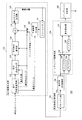
図2は、シーンチェンジ検出部120を示す。シーンチェンジ検出部120は、縮小画像生成部130と、周波数成分取得部150と、シーンチェンジ度算出部160と、シーンチェンジ判定部180を備える。
FIG. 2 shows the scene
縮小画像生成部130は、MPEG−2ストリームを部分的にデコードし、該ストリームが表わす動画像を構成する複数のピクチャの縮小画像を符号化順に取得して周波数成分取得部150に出力する。周波数成分取得部150は、縮小画像生成部130からの各縮小画像の周波数成分をそれぞれ抽出してシーンチェンジ度算出部160に出力する。シーンチェンジ度算出部160は、周波数成分取得部150により得られた各縮小画像の周波数成分を表示順に並び替えて、連続する2つの画像毎に、周波数成分の差分を求める。これらの差分は、シーンチェンジの可能性の大小を示すシーンチェンジ度としてシーンチェンジ度算出部160からシーンチェンジ判定部180に出力される。シーンチェンジ判定部180は、シーンチェンジ度算出部160が算出したシーンチェンジ度を所定の閾値と比較することによりシーンチェンジの有無を判定する。具体的には、シーンチェンジ度が上記閾値以上であれば、シーンチェンジが生じたと判定すると共に、該当箇所を示すシーンチェンジ検出情報をH.264エンコーダ114に出力する。
The reduced
図3に示す具体例を参照して、シーンチェンジ検出部120の各機能ブロックの動作を説明する。
縮小画像生成部130は、部分可変長復号部132と、部分逆量子化部134と、平均成分復元部136と、加算器138と、セレクタ140と、予測画素作成部142、フレームメモリ144、縮小ピクチャ生成部146を備える。なお、縮小画像生成部130は、MPEG−2ストリームが表わす動画像の各ピクチャの低周波成分のみをデコードする点を除き、通常のMPEG−2デコーダと同様の動作をするため、ここでは簡単に説明する。
The operation of each functional block of the scene
The reduced
部分可変長復号部132は、ピクチャヘッダからピクチャ符号化タイプや量子化マトリクスなど、低周波数成分のデコードに必要なデータを復号し、また、MBヘッダ毎にMB符号化タイプ、動きベクトル、量子化幅を復号する。
The partial variable
部分逆量子化部134と平均成分復元部136は、ブロック毎に最初のDCT係数を復号する。具体的には、イントラMBでは、周波数(0,0)成分となるDC係数予測誤差を復号し、イントラMB以外では予測誤差係数の周波数(0,0)成分を復号する。なお、イントラMBの場合、DC係数予測値を用いてDC係数を復号する。
The partial
加算器138は、平均成分復元部136の出力とセレクタ140の出力を加算してブロックの平均成分を得る。セレクタ140は、イントラMBについてイントラ予測値(8bit画像の場合は128)を出力し、イントラMB以外については予測画素作成部142が作成した予測値を出力する。すなわち、加算器138は、イントラMBについて、平均成分復元部136からのDC成分と、セレクタ140からのイントラ予測値を加算して該イントラMBの各ブロックの平均成分を得る。イントラMB以外については、平均成分復元部136からの予測誤差係数の周波数(0,0)成分と、セレクタ140からの、予測画素作成部142が作成した予測値とを加算して該MBの各ブロックの平均成分を得る。
The
予測画素作成部142は、イントラMB以外のMBについて、部分可変長復号部132が得た動きベクトルを1/8に縮小した動きベクトルと、フレームメモリ144に格納された前方参照画像または後方参照画像とを用いて予測値を作成する。ここで動きベクトルを1/8に縮小するのは、8画素×8ラインのブロックを平均成分からなる1画素に縮小するのに合わせるためである。
The prediction
縮小ピクチャ生成部146は、ピクチャ毎に、加算器138から出力された各ブロックの平均成分を集めて縮小画像を生成する。これらは、各ピクチャの縮小画像である。ブロックのサイズはが8画素×8ラインであるので、縮小ピクチャ生成部146が作成した画像の大きさは、完全に復号した場合の1/8×1/8である。例えば、入力されたMPEG−2ストリームの各ピクチャが1920画素×1080ラインであるときに、縮小ピクチャ生成部146から出力された縮小画像は、輝度(Y)は240画素×136ラインであり、色差(Cb、Cr)は120画素×68ラインである。
The reduced
縮小ピクチャ生成部146は、生成した各縮小画像を順次周波数成分取得部150に出力する。また、縮小ピクチャ生成部146は、IピクチャとPピクチャについては、それらの縮小画像をフレームメモリ144にも出力する。これらの縮小画像は、後続のPピクチャまたはBピクチャの前方参照画像または後方参照画像として予測画素作成部142に用いられる。
The reduced
図3に示すように、縮小画像生成部130からの縮小画像の出力順は、MPEG−2ストリームにおける並び順すなわち符号化順と同一である。
As shown in FIG. 3, the output order of the reduced images from the reduced
周波数成分取得部150は、ブロック化部152と順方向DCT変換部154を有し、縮小ピクチャ生成部146からの各縮小画像の周波数成分をそれぞれ抽出してシーンチェンジ度算出部160に供する。
The frequency
ブロック化部152は、縮小画像のY、Cb、Crをそれぞれ8画素×8画素のブロックに縮小して順方向DCT変換部154に出力する。例えば、入力されたMPEG−2ストリームが1920画素×1080ラインの場合には、縮小画像のYを30画素×16ライン単位の領域に分割して各領域の平均値を求め、Cb、Crについては15画素×8ライン単位の領域に分割して各領域の平均値を求める。
The blocking
順方向DCT変換部154は、8×8DCT変換を行って縮小画像毎に、Y、Cb、Crにつきそれぞれ8×8個の変換係数(DCT係数)を求めてシーンチェンジ度算出部160に出力する。すなわち、本実施の形態において、周波数成分取得部150は、DCT係数を周波数成分として取得する。
The forward
図3に示すように、周波数成分取得部150からの周波数成分の出力順も、符号化順である。
As shown in FIG. 3, the output order of frequency components from the frequency
シーンチェンジ度算出部160は、バッファ162、バッファ164、セレクタ166、バッファ168、差分算出部170を備える。
The scene change
バッファ162、バッファ164、セレクタ166は、協働して、周波数成分取得部150から出力された周波数成分を表示順に並べ替えて差分算出部170とバッファ168に出力する。図3に示すように、セレクタ166からは、各周波数成分は、表示順に出力されている。
The
差分算出部170は、セレクタ166から現在出力してきた縮小画像の周波数成分と、バッファ168に格納された1つ前の縮小画像の周波数成分との差分を求めてシーンチェンジ判定部180に出力する。図3に示すように、バッファ168は、セレクタ166が現在出力した縮小画像の周波数成分の1つ前の縮小画像の周波数成分を出力するようになっている。
The
なお、本実施の形態において、差分算出部170は、周波数が低いほど重み付け係数が大きくなるように周波数成分を重み付けした上で、2つの縮小画像間の周波数成分の差分を求める。具体的には、下記の式(1)に従って差分を求める。なお、周波数成分は64成分あるが、高周波成分の重み付け係数を0にして、格納する周波数成分の数を減らすこともできる。
差分=Σw(m,n)*|Fi(m,n)−Fi(m,n)| (1)
但し,Fi(m,n): 縮小画像iの周波数(m,n)成分
Fj(m,n): 縮小画像jの周波数(m,n)成分
w(m,n): 周波数w(m,n)の重み付け係数
In the present embodiment, the
Difference = Σw (m, n) * | Fi (m, n) −Fi (m, n) | (1)
Where Fi (m, n): frequency (m, n) component of the reduced image i
Fj (m, n): Frequency (m, n) component of reduced image j
w (m, n): Weighting factor for frequency w (m, n)
シーンチェンジ判定部180は、シーンチェンジ度算出部160が算出したシーンチェンジ度を閾値と順次比較し、シーンチェンジ度が上記閾値以上であれば、シーンチェンジが生じたと判定すると共に、該当箇所を示すシーンチェンジ検出情報をH.264エンコーダ114に出力する。
The scene
本実施の形態の録画装置100によれば、動画像データから生成した縮小画像の周波数成分を取得して表示順に並び変えることによって、表示順で連続する2つのフレーム間の周波数成分の差分によりシーンチェンジ検出を可能にしたため、確実にシーンチェンジを検出できる。
According to the
図4は、ある1920画素×1080ラインの画像のストリームに対して、ピクチャ毎に求められた各種MBの数を示す。図中横軸は、分かりやすいように、表示順のピクチャ番号を示す。このストリームは、ピクチャ番号3、18、33、48、51がIピクチャの「M=3」タイプである。また、このストリームは、43番ピクチャ〜53番ピクチャあたりまでが白フェードアウトであり、57番のPピクチャでシーンチェンジが生じている。
FIG. 4 shows the number of various MBs obtained for each picture with respect to an image stream of a certain 1920 pixels × 1080 lines. In the figure, the horizontal axis indicates picture numbers in display order for easy understanding. In this stream,
図示のように、フェードアウトの箇所とシーンチェンジが生じた箇所間で、イントラMBの数や、予測MBの数などの差が不明確である。たとえば45番と54番のPピクチャではイントラMBがそれぞれ過半数の約4000個、5400個と多くなり、従来技術ではシーンチェンジとみなされる可能性がある。また52番のBピクチャでも逆方向および両方向MB数が通常より少なく、シーンチェンジとみなされる可能性がある。またこのストリームは17、32番のようにGOPの最終のBピクチャで順方向予測MB及び両方向予測MBが通常より少なくなっており、やはりシーンチェンジとみなされる可能性がある。 As shown in the figure, the difference in the number of intra MBs, the number of predicted MBs, etc. is unclear between the fade-out part and the part where the scene change has occurred. For example, in the 45th and 54th P-pictures, the number of intra MBs increases to approximately 4000 and 5400, which are the majority, respectively, and may be regarded as a scene change in the prior art. In the 52nd B picture, the number of backward and bidirectional MBs is smaller than usual, and there is a possibility of being regarded as a scene change. In addition, this stream has the forward prediction MB and the bidirectional prediction MB less than usual in the last B picture of GOP as in Nos. 17 and 32, and may be regarded as a scene change.
図5は、本実施の形態の録画装置100により同一のストリームに対して処理を行った結果、差分算出部170が得た周波数成分の差分を示す。図から分かるように、シーンチェンジ箇所の差分が、他の箇所(白フェードアウトの箇所を含む)に対して算出した差分より突出した大きさを有する。そのため、シーンチェンジの検出精度が高い。また白フェードアウト部分も他の部分と比較して差分が大きく、識別可能であり、再圧縮の際の符号化情報として利用可能である。
<第2の実施の形態>
FIG. 5 shows the frequency component difference obtained by the
<Second Embodiment>
本発明の第2の実施の形態も録画装置である。この録画装置は、シーンチェンジ検出部が録画装置100のシーンチェンジ検出部120と異なる点を除き、録画装置100と同様の構成を有する。ここでは本第2の実施の形態にかかる録画装置におけるシーンチェンジ検出部220についてのみ説明する。
The second embodiment of the present invention is also a recording apparatus. This recording apparatus has the same configuration as the
図6は、シーンチェンジ検出部220を示す。なお、図6において、図2に示すシーンチェンジ検出部120のものと同一の構成要素に対して同一の符号を付与し、これらの構成要素の説明を省略する。
FIG. 6 shows the scene
図6に示すように、シーンチェンジ検出部220のシーンチェンジ度算出部260は、シーンチェンジ検出部120のシーンチェンジ度算出部160と異なる。また、シーンチェンジ度算出部260は、セレクタ166とバッファ168との間に演算器262が追加された点を除き、シーンチェンジ度算出部160と同様である。
As shown in FIG. 6, the scene change
演算器262は、セレクタ166の出力(現ピクチャの周波数成分「i」)と、バッファ168の出力(過去の周波数成分「i」)が入力され、それらの平均値(周波数成分「i」)を算出してバッファ168に出力するものである。すなわち、演算器262とバッファ168は、セレクタ166から出力された各周波数成分に対する時間方向の無限インパルス応答フィルタを構成する。演算器262とバッファ168により実現される処理は、式(2)に示す。
The
周波数成分[i]=現ピクチャの周波数成分[i]/2+過去の周波数成分[i])/2 (2) Frequency component [i] = frequency component of current picture [i] / 2 + past frequency component [i]) / 2 (2)
第1の実施の形態の録画装置100において、シーンチェンジ度算出部160は、セレクタ166から現在出力された縮小画像の周波数成分(現ピクチャ周波数成分「i」)と、バッファ168に格納された1つ前の縮小画像の周波数成分との差分を求めている。ところでストリームによっては、照明が変化したりして、短時間で明るさや色調が変わることもある。このようなストリームでは、ピクチャ毎の周波数成分の低周波数成分が変動し、録画装置100においてもシーンチェンジを誤検出する可能性がある。本第2の実施の形態の録画装置は、このようなストリームにも対応できるようにしたものであり、そのシーンチェンジ度算出部260において、セレクタ166が出力した各周波数成分に時間方向の無限インパルス応答フィルタをかけてから差分算出部170に出力する。
In the
こうすることにより、直前の1枚のピクチャの周波数成分ではなく、過去のピクチャの周波数成分が加味された周波数成分との差分が求められるため、照明が変化する画像に対してもシーンチェンジ検出の精度を上げることができる。 In this way, the difference between the frequency component of the previous picture and the frequency component of the previous picture is obtained instead of the frequency component of the previous picture. The accuracy can be increased.
以上、実施の形態をもとに本発明を説明した。実施の形態は例示であり、本発明の主旨から逸脱しない限り、上述した実施の形態に対してさまざまな変更、増減を行ってもよい。これらの変更、増減が行われた変形例も本発明の範囲にあることは当業者に理解されるところである。 The present invention has been described above based on the embodiment. The embodiment is an exemplification, and various modifications and changes may be made to the above-described embodiment without departing from the gist of the present invention. It will be understood by those skilled in the art that modifications in which these changes and increases / decreases are also within the scope of the present invention.
例えば、ビデオ録画装置では、録画したビデオのシーンの検索や、ビデオ編集の開始点とするためにシーンチェンジが生じたGOPの検出がなされている。ビデオの編集は、GOP単位で行われることが多いので、必ずしもピクチャ単位で行われるとは限らない。そのため、編集のためのシーンチェンジ検出を行う際に、シーンチェンジ検出部120またはシーンチェンジ検出部220の手法と同様に縮小画像を生成して周波数成分を抽出し、連続する2つのGOPの先頭Iピクチャの縮小画像間で周波数成分の差分を求めて閾値と比較することによりシーンチェンジが生じたGOPの検出を行うことができる。ここでIピクチャを選ぶのは、部分デコードがPピクチャやBピクチャより簡単なためである。
For example, in a video recording apparatus, a GOP in which a scene change has occurred is detected in order to search for a recorded video scene or to start video editing. Since video editing is often performed in GOP units, it is not always performed in picture units. Therefore, when scene change detection for editing is performed, a reduced image is generated and frequency components are extracted in the same manner as the method of the scene
また、ビデオ録画装置では、ストリームを録画しながら別ストリームをデコードして再生する場合や、複数のストリームを録画する場合があり、これらの場合にはMPEG2デコーダの性能制限により、録画するストリームを全てビデオにデコードできない、すなわち再圧縮できないことがある。この場合には、入力ストリームをいったんそのまま記録しておき、後で再圧縮するが、このような場合でも、ビデオ編集のためにあらかじめシーンチェンジ検出ができていると便利である。そのため、入力ストリームの記録時に、シーンチェンジ検出部120の手法と同様にシーンチェンジ検出を行って、シーンチェンジ情報を付属情報としてストリームに付属させるようにすればよい。本発明の方法は、ハードウェア、ソフトウエアのどちらで実現するにしても、MPEG2デコーダよりは必要な処理が少なく、実現しやすいという特徴がある。
The video recording device may decode and reproduce another stream while recording a stream, or may record a plurality of streams. In these cases, all the streams to be recorded are recorded due to performance limitations of the MPEG2 decoder. Sometimes video cannot be decoded, ie not recompressed. In this case, the input stream is recorded once as it is and then recompressed later. Even in such a case, it is convenient if the scene change can be detected in advance for video editing. Therefore, at the time of recording the input stream, scene change detection may be performed in the same manner as the method of the scene
100 録画装置
110 録画部
112 MPEG−2デコーダ
114 H.264エンコーダ
120 シーンチェンジ検出部
130 縮小画像生成部
132 部分可変長復号部
134 部分逆量子化部
136 平均成分復元部
138 加算器
140 セレクタ
142 予測画素作成部
144 フレームメモリ
146 縮小ピクチャ生成部
150 周波数成分取得部
152 ブロック化部
154 順方向DCT変換部
160 シーンチェンジ度算出部
162 バッファ
164 バッファ
166 セレクタ
168 バッファ
170 差分算出部
180 シーンチェンジ判定部
220 シーンチェンジ検出部
260 シーンチェンジ度算出部
262 演算器
100
Claims (6)
該縮小画像生成部により得られた前記複数の縮小画像の周波数成分をそれぞれ抽出する周波数成分取得部と、
前記複数の縮小画像の周波数成分を表示順に並び替えて、シーンチェンジの可能性の大小を示すシーンチェンジ度として、連続する2つの縮小画像毎に、または連続する2つのGOPの先頭Iピクチャの縮小画像毎に、前記周波数成分取得部が取得した周波数成分の差分を求めるシーンチェンジ度算出部とを備えることを特徴とする画像処理装置。 A reduced image generating unit that acquires reduced images of a plurality of pictures constituting the moving image from the moving image data compressed by a compression method using interframe or field motion compensation;
A frequency component acquisition unit that respectively extracts frequency components of the plurality of reduced images obtained by the reduced image generation unit;
The frequency components of the plurality of reduced images are rearranged in the display order, and the scene change degree indicating the magnitude of the possibility of scene change is reduced for each two consecutive reduced images or for the first I picture of two consecutive GOPs. An image processing apparatus comprising: a scene change degree calculation unit that obtains a difference between frequency components acquired by the frequency component acquisition unit for each image.
前記縮小画像生成部は、前記動画像の各ピクチャの直交変換係数を部分的にデコードすることにより前記縮小画像を得ることを特徴とする請求項4に記載の画像処理装置。 The moving picture is encoded with the orthogonal transform coefficient of a block in a picture, or the orthogonal transform coefficient of a prediction error block obtained by performing motion compensation between frames or fields with reference to past and / or future pictures. Compressed with the compression method
The image processing apparatus according to claim 4, wherein the reduced image generation unit obtains the reduced image by partially decoding orthogonal transform coefficients of each picture of the moving image.
Priority Applications (1)
| Application Number | Priority Date | Filing Date | Title |
|---|---|---|---|
| JP2009283841A JP2011129979A (en) | 2009-12-15 | 2009-12-15 | Image processor |
Applications Claiming Priority (1)
| Application Number | Priority Date | Filing Date | Title |
|---|---|---|---|
| JP2009283841A JP2011129979A (en) | 2009-12-15 | 2009-12-15 | Image processor |
Publications (1)
| Publication Number | Publication Date |
|---|---|
| JP2011129979A true JP2011129979A (en) | 2011-06-30 |
Family
ID=44292130
Family Applications (1)
| Application Number | Title | Priority Date | Filing Date |
|---|---|---|---|
| JP2009283841A Pending JP2011129979A (en) | 2009-12-15 | 2009-12-15 | Image processor |
Country Status (1)
| Country | Link |
|---|---|
| JP (1) | JP2011129979A (en) |
Cited By (2)
| Publication number | Priority date | Publication date | Assignee | Title |
|---|---|---|---|---|
| WO2022113430A1 (en) * | 2020-11-27 | 2022-06-02 | シャープ株式会社 | Image processing device, display device, and image processing method |
| WO2024018166A1 (en) * | 2022-07-22 | 2024-01-25 | Blackbird Plc | Computer-implemented methods of blurring a digital image; computer terminals and computer program products |
-
2009
- 2009-12-15 JP JP2009283841A patent/JP2011129979A/en active Pending
Cited By (2)
| Publication number | Priority date | Publication date | Assignee | Title |
|---|---|---|---|---|
| WO2022113430A1 (en) * | 2020-11-27 | 2022-06-02 | シャープ株式会社 | Image processing device, display device, and image processing method |
| WO2024018166A1 (en) * | 2022-07-22 | 2024-01-25 | Blackbird Plc | Computer-implemented methods of blurring a digital image; computer terminals and computer program products |
Similar Documents
| Publication | Publication Date | Title |
|---|---|---|
| JP5242404B2 (en) | Adaptive GOP structure in video streaming | |
| US7068722B2 (en) | Content adaptive video processor using motion compensation | |
| JP3957915B2 (en) | Fade detection device and information encoding device | |
| KR101240119B1 (en) | Inverse telecine techniques | |
| EP1845735A1 (en) | Moving picture encoding method, and apparatus and computer program using the same | |
| JP4875007B2 (en) | Moving picture coding apparatus, moving picture coding method, and moving picture decoding apparatus | |
| US7822123B2 (en) | Efficient repeat padding for hybrid video sequence with arbitrary video resolution | |
| JP2008167449A (en) | Method and apparatus for encoding/decoding image | |
| US7839933B2 (en) | Adaptive vertical macroblock alignment for mixed frame video sequences | |
| US8165217B2 (en) | Image decoding apparatus and method for decoding prediction encoded image data | |
| US20150249829A1 (en) | Method, Apparatus and Computer Program Product for Video Compression | |
| JP5068316B2 (en) | Video encoding | |
| JP2006203598A (en) | Digital image decoder and decoding method | |
| JP2006203597A (en) | Digital image decoder and decoding method | |
| US8503520B2 (en) | Method and apparatus for encoding a flash picture occurring in a video sequence, and for decoding corresponding data for a flash picture | |
| JP2011129979A (en) | Image processor | |
| JP2009218965A (en) | Image processor, imaging device mounted with the same and image reproduction device | |
| JP2008311824A (en) | Image encoding device, and image encoding program | |
| JP2000333180A (en) | Skip macro block inhibit control method, skip macro block inhibit controller and medium recording skip macro block inhibit control program | |
| JP4302093B2 (en) | Moving picture coding apparatus and moving picture coding method | |
| JP3756902B2 (en) | Moving picture decoding apparatus and moving picture decoding method | |
| JP3756900B2 (en) | Moving picture decoding apparatus and moving picture decoding method | |
| JP3756901B2 (en) | Moving picture decoding apparatus and moving picture decoding method | |
| JP4302094B2 (en) | Moving picture decoding apparatus and moving picture decoding method | |
| JP3756899B2 (en) | Moving picture decoding apparatus and moving picture decoding method |