JP2011090311A - Linear prediction voice coder in mixed domain of multimode of closed loop - Google Patents
Linear prediction voice coder in mixed domain of multimode of closed loop Download PDFInfo
- Publication number
- JP2011090311A JP2011090311A JP2010249991A JP2010249991A JP2011090311A JP 2011090311 A JP2011090311 A JP 2011090311A JP 2010249991 A JP2010249991 A JP 2010249991A JP 2010249991 A JP2010249991 A JP 2010249991A JP 2011090311 A JP2011090311 A JP 2011090311A
- Authority
- JP
- Japan
- Prior art keywords
- frame
- speech
- frequency
- encoding
- mode
- Prior art date
- Legal status (The legal status is an assumption and is not a legal conclusion. Google has not performed a legal analysis and makes no representation as to the accuracy of the status listed.)
- Pending
Links
Images


Landscapes
- Compression, Expansion, Code Conversion, And Decoders (AREA)
Abstract
Description
本発明は、概ね音声処理の分野、とくに音声を閉ループのマルチモードの混合領域でコード化するための方法および装置に関する。 The present invention relates generally to the field of speech processing, and more particularly to a method and apparatus for encoding speech in a closed-loop multi-mode mixed domain.
ディジタル技術による音声(voice)の伝送は、とくに長距離のディジタル無線電話の応用において普及してきた。これにより、チャンネル上で送ることができる最少情報量を判断し、一方で再構成された音声の知覚品質を維持することに関心が生まれた。音声を単にサンプリングして、ディジタル形式にすることによって送るとき、従来のアナログ電話の音声品質を実現するには、毎秒64キロビット秒(kbps)のオーダのデータレートが必要である。しかしながら、音声解析を使用し、その後で適切にコード化し、伝送し、受信機において再合成をすることによって、データレートを相当に低減することができる。 The transmission of voice through digital technology has become widespread, especially in long-distance digital radiotelephone applications. This has generated interest in determining the minimum amount of information that can be sent on a channel while maintaining the perceived quality of the reconstructed speech. When voice is simply sampled and sent in digital form, data rates on the order of 64 kilobit seconds per second (kbps) are required to achieve the voice quality of conventional analog telephones. However, the data rate can be significantly reduced by using speech analysis and then properly encoding, transmitting and recombining at the receiver.
人間の音声の生成モデルに関係するパラメータを抽出することによって音声を圧縮する技術を採用したデバイスは、音声コーダと呼ばれている。音声コーダは、入力音声信号を時間のブロック、すなわち解析フレームに分割する。一般的に音声コーダはエンコーダとデコーダとを含む。エンコーダは、入力音声フレームを解析して、一定の関連するパラメータを抽出して、パラメータを二値表現、すなわち1組のビットまたは二値データパケットに量子化する。データパケットは通信チャンネル上で受信機およびデコーダへ送られる。デコーダはデータパケットを処理し、非量子化して(unquantize)パラメータを生成し、非量子化したパラメータを使用して音声フレームを再合成する。 A device that employs a technology for compressing speech by extracting parameters related to a human speech generation model is called a speech coder. The speech coder divides the input speech signal into blocks of time, ie analysis frames. In general, a speech coder includes an encoder and a decoder. The encoder parses the input speech frame, extracts certain relevant parameters, and quantizes the parameters into a binary representation, ie a set of bits or binary data packets. Data packets are sent over a communication channel to a receiver and a decoder. The decoder processes the data packet, unquantizes to generate parameters, and re-synthesizes the speech frame using the unquantized parameters.
音声コーダの機能は、音声が本質的にもっている固有の冗長の全てを取去ることによって、ディジタル化された音声信号を低ビットレートの信号へ圧縮することである。ディジタル圧縮は、入力音声フレームを1組のパラメータで表わし、量子化を採用して、このパラメータを1組のビットで表わすことによって実現される。入力音声フレームが多数のビットNiをもち、音声コーダによって生成されるデータパケットが多数のビットN0をもつとき、音声コーダによって得られる圧縮係数は、Cr=Ni/N0である。デコードされた音声(speech)の高い音声品質(voice quality)を維持し、一方で目標の圧縮係数を得ることが課題とされている。音声コーダの性能は、(1)音声モデル、すなわち上述の解析および合成プロセスの組合せがどのくらい適切に行われるか、および(2)パラメータ量子化プロセスが1フレーム当りN0ビットの目標ビットレートでどのくらい適切に実行されるかに依存する。したがって音声モデルは、各フレームごとの小さい組のパラメータを使用して、音声信号の本質(essence)、すなわち目標の音声品質を得ることを目的としている。 The function of the voice coder is to compress the digitized voice signal into a low bit rate signal by removing all of the inherent redundancy that the voice inherently has. Digital compression is implemented by representing an input speech frame with a set of parameters, employing quantization and representing the parameters with a set of bits. When the input speech frame has a number of bits N i and the data packet generated by the speech coder has a number of bits N 0 , the compression factor obtained by the speech coder is C r = N i / N 0 . The challenge is to maintain the high voice quality of the decoded speech while obtaining the target compression factor. The performance of a speech coder is: (1) how well the speech model, ie the combination of the above analysis and synthesis processes, is performed, and (2) how much the parameter quantization process is at a target bit rate of N 0 bits per frame. Depends on proper execution. The speech model is therefore aimed at obtaining the essence of the speech signal, ie the target speech quality, using a small set of parameters for each frame.
音声コーダは時間領域のコーダ、すなわち音声の小さいセグメント(一般的に5ミリ秒(millisecond, ms)のサブフレーム)を一度にコード化する高度な時間分解処理(time-resolution processing)を採用することによって時間領域の音声波形を得ることを試みる時間領域のコーダとして構成することができる。各サブフレームごとに、この技術において知られている種々のサーチアルゴリズムによって、コードブック空間から高精度の見本(representative)を見付ける。その代わりに、音声コーダは周波数領域のコーダとして構成されていてもよく、1組のパラメータを使用して入力音声フレームの短期間の音声スペクトルを捕らえて(解析)、対応する合成プロセスを採用して、スペクトルパラメータから音声波形を再現することを試みる。パラメータ量子化器は、文献(A Gersho & R.M. Gray, Vector Quantization and Signal Compression (1992))に記載されている既知の量子化技術にしたがって、コードベクトルの記憶されている表現を使用してパラメータを表わすことによってそれらのパラメータを保存する。 Speech coders employ time-domain coders, ie, advanced time-resolution processing that encodes a small segment of speech (typically a millisecond, ms subframe) at a time. Can be configured as a time domain coder attempting to obtain a time domain speech waveform. For each subframe, a high-precision representative is found from the codebook space by various search algorithms known in the art. Instead, the speech coder may be configured as a frequency domain coder, using a set of parameters to capture (analyze) the short-term speech spectrum of the input speech frame and employ a corresponding synthesis process. Then, try to reproduce the speech waveform from the spectral parameters. The parameter quantizer uses a stored representation of the code vector to parameterize according to known quantization techniques described in the literature (A Gersho & RM Gray, Vector Quantization and Signal Compression (1992)). Save those parameters by representing them.
よく知られている時間領域の音声コーダは、CELP(Code Excited Linear Predictive)コーダであり、これはL.B. Rabiner & R.W. Schaferによる文献(Digital Processing of Speech Signals 396-453 (1978))に記載されており、ここでは参考文献として全体的にこれを取り上げている。CELPコーダでは、線形予測(linear prediction, LP)解析によって、短期間のフォルマントフィルタの係数を見付け、音声信号における短期間の相関関係、すなわち冗長を取去る。短期間の予測フィルタを入力音声フレームに適用して、LPの残余信号(residue signal)を生成し、このLPの残余信号をさらに長期間の予測フィルタパラメータおよび次の確率コードブックでモデル化して、量子化する。したがってCELPのコード化は、時間領域の音声波形をコード化するタスクを、LPの短期間のフィルタ係数をコード化するタスクおよびLPの残余をコード化するタスクの別々のタスクへ分ける。時間領域のコード化は、固定レート(すなわち、各フレームごとに、同数のビットN0を使用するレート)で、または可変レート(すなわち、異なるビットレートが異なるタイプのフレームの内容に対して使用されるレート)で実行することができる。可変レートのコーダは、目標の品質を得るのに適したレベルまでコーデックパラメータをコード化するのに必要なビット量のみを使用することを試みる。例示的な可変レートのCELPのコーダは米国特許第5,414,796号に記載されており、これは本発明の譲受人に譲渡され、ここでは参考文献として全体的に取り上げている。 A well-known time domain speech coder is the Code Excited Linear Predictive (CELP) coder, which is described in the literature by LB Rabiner & RW Schafer (Digital Processing of Speech Signals 396-453 (1978)). This is a general reference here. The CELP coder finds short-term formant filter coefficients by linear prediction (LP) analysis, and removes short-term correlations, ie, redundancy, in the speech signal. A short-term prediction filter is applied to the input speech frame to generate an LP residual signal, which is modeled with a longer-term prediction filter parameter and the following probability codebook: Quantize. Thus, CELP coding divides the task of coding the time-domain speech waveform into separate tasks: the task of coding the short-term filter coefficients of LP and the task of coding the remainder of LP. Time domain coding is used at a fixed rate (ie, a rate that uses the same number of bits N 0 for each frame) or at a variable rate (ie, different bit rates for different types of frame content). At a rate). A variable rate coder attempts to use only the amount of bits necessary to code the codec parameters to a level suitable to achieve the target quality. An exemplary variable rate CELP coder is described in US Pat. No. 5,414,796, which is assigned to the assignee of the present invention and is generally incorporated herein by reference.
CELPコーダのような時間領域のコーダは、通常は、フレームごとに多数のビットN0に依存して、時間領域の音声波形の精度を保持する。このようなコーダは、通常はフレーム当りのビット数N0が比較的に多いとき(例えば、8キロビット秒以上)、優れた音声品質を伝える。しかしながら低ビットレート(4キロビット秒以下)では、時間領域のコーダは、使用可能なビット数が制限されているために、高品質で丈夫な性能を維持しない。低ビットレートではコードブック空間が制限されているので、従来の時間領域のコーダには備えられている波形を整合する能力を取去って、より高レートの市販のアプリケーションにおいてこのようなコーダを実行するのに成功した。 Time domain coders, such as CELP coders, typically rely on a number of bits N 0 per frame to maintain the accuracy of the time domain speech waveform. Such a coder usually conveys excellent voice quality when the number of bits N 0 per frame is relatively high (eg, 8 kilobit seconds or more). However, at low bit rates (below 4 kilobit seconds), time domain coders do not maintain high quality and robust performance due to the limited number of available bits. Because the codebook space is limited at low bit rates, it removes the ability to match the waveforms provided by traditional time domain coders and runs such coders in higher rate commercial applications. Succeeded to do.
現在、研究に対する関心および活発な商業上の要求が急激に高まり、中程度から低いビットレート(すなわち、2.4ないし4キロビット秒の範囲およびそれ以下)で動作する高品質の音声コーダを発展させた。応用分野には、無線電話通信、衛星通信、インターネット電話通信、種々のマルチメディアおよび音声ストリーミングアプリケーション、音声メール、並びに他の音声保存システムを含む。駆動力については、大きい容量が必要とされ、かつパケットが失われた情況下での丈夫な性能が要求されている。種々の最近の音声のコード化を標準化する努力は、低レートの音声コード化アルゴリズムの研究および発展を推進する別の直接的な駆動力に当てられている。低レートの音声コーダは、許容可能な適用バンド幅ごとに、より多くのチャンネル、すなわちユーザを生成し、低レートの音声コーダを適切なチャンネルコーディングの追加の層と結合して、コーダの全体的なビット予定値(bit budget)の仕様に適合させ、チャンネルを誤った情況のもとでも丈夫な性能を発揮させることができる。 Currently, research interest and active commercial demands have increased rapidly, developing high quality speech coders that operate at moderate to low bit rates (ie, in the 2.4 to 4 kilobit second range and below). It was. Applications include wireless telephony, satellite communications, internet telephony, various multimedia and voice streaming applications, voice mail, and other voice storage systems. With respect to driving force, a large capacity is required, and robust performance is required under circumstances where packets are lost. The efforts to standardize various recent speech coding are devoted to another direct driving force that drives the research and development of low-rate speech coding algorithms. A low-rate speech coder generates more channels, or users, for each acceptable application bandwidth, and combines the low-rate speech coder with an additional layer of appropriate channel coding to make the overall coder It can be adapted to the specifications of the correct bit budget, and the channel can be made robust even under the wrong circumstances.
より低いビットレートでコード化するために、音声のスペクトル、すなわち周波数領域でコード化する種々の方法が開発され、この方法では音声信号は、時間にしたがって漸進的に変化するスペクトル(time-varying evolution of spectra)として解析される。例えば、R.J. McAulay & T.F. Quatieriによる文献(Sinusoidal Coding, in Speech Coding and Synthesis ch. 4 (W.B. Kleijin & K.K. Paliwal eds., 1995)参照。スペクトルコーダは、時間にしたがって変化する音声波形を精密にまねるのではなく、1組のスペクトルパラメータを使用して、音声の各入力フレームの短期間の音声スペクトルをモデル化、すなわち予測することを目的とする。スペクトルパラメータはコード化され、音声の出力フレームはデコードされたパラメータを使用して生成される。生成された合成された音声は、元の入力音声波形と整合しないが、同様の知覚品質を与える。この技術においてよく知られている周波数領域コーダの例には、マルチバンド励起コーダ(multiband excitation coder, MBE)、シヌソイド変換コーダ(sinusoidal transform coder, STC)、高調波コーダ(harmonic coder, HC)を含む。このような周波数領域のコーダは、低ビットレートで使用可能な少数のビットで正確に量子化できるコンパクトな組のパラメータをもつ高品質のパラメータモデルを与える。 In order to code at lower bit rates, various methods of coding the speech spectrum, ie in the frequency domain, have been developed, in which the speech signal is a time-varying evolution spectrum. of spectra). For example, see RJ McAulay & TF Quatieri's document (Sinusoidal Coding, in Speech Coding and Synthesis ch. 4 (WB Kleijin & KK Paliwal eds., 1995). Rather, it aims to model or predict the short-term speech spectrum of each input frame of speech using a set of spectral parameters, where the spectral parameters are coded and the speech output frame is decoded. The generated synthesized speech does not match the original input speech waveform, but provides similar perceptual quality.Examples of frequency domain coders well known in the art Includes multiband excitation coder (MBE), sinusoidal transform coder (STC), harmonic coder harmonic coder, including HC). coder of such frequency range, give a high-quality parametric model of having a compact set of parameters that can be accurately quantized with fewer bits available at low bit rates.
それにも関わらず、低ビットレートのコード化は、制限されたコード化分解能、すなわち制限されたコードブック空間に重大な制約を加えて、単一のコード化機構の効果を制限し、コーダが、等しい精度の種々の背景条件のもとで、種々のタイプの音声セグメントを表わすことができないようにしている。例えば、従来の低ビットレートの周波数領域のコーダは、音声フレームの位相情報を送らない。その代わりに、位相情報は、ランダムな人工的に生成された初期位相値および線形補間技術(linear interpolation technique)を使用することによって再構成される。例えば、H.Yang、他による文献(Quadratic Phase Interpolation for Voiced Speech Synthesis in the MBE Model, in 29 Electronic Letters 856-57 (May 1993))参照。位相情報は人工的に生成されるので、シヌソイドの振幅は量子化−非量子化プロセスによって完全に保持されるときでも、周波数領域のコーダによって生成される出力音声は元の入力音声と整合しない(例えば、大半のパルスは同期しない)。したがって、周波数領域のコーダでは、例えば信号対雑音比(signal-to-noise ratio, SNR)または知覚のSNRのような、閉ループの性能尺度(performance measure)を採用することが難しいことが分かった。 Nevertheless, low bit rate coding adds significant constraints to limited coding resolution, i.e., limited codebook space, limiting the effectiveness of a single coding mechanism, Various types of speech segments cannot be represented under various background conditions of equal precision. For example, conventional low bit rate frequency domain coders do not send audio frame phase information. Instead, the phase information is reconstructed by using random artificially generated initial phase values and a linear interpolation technique. See, for example, H. Yang et al. (Quadratic Phase Interpolation for Voiced Speech Synthesis in the MBE Model, in 29 Electronic Letters 856-57 (May 1993)). Since the phase information is artificially generated, the output speech produced by the frequency domain coder does not match the original input speech even when the sinusoid amplitude is fully preserved by the quantization-dequantization process ( For example, most pulses are not synchronized). Thus, it has been found difficult for frequency domain coders to employ closed-loop performance measures, such as signal-to-noise ratio (SNR) or perceptual SNR.
開ループのモード決定プロセスに関連して低レートの音声のコード化を行なうために、マルチモードコード化技術が採用された。1つのこのようなマルチモードコード化技術は、Amitava Das、他による文献(Multimode and Variable-Rate Coding of Speech, in Speech Coding and Synthesis ch. 7 (W.B. Kleijin & K.K. Paliwal eds., 1995))に記載されている。従来のマルチモードコーダは異なるモード、すなわちコード化−デコード化アルゴリズムを、異なるタイプの入力音声フレームへ適用する。各モード、すなわちコード化−デコード化プロセスは、最も効率的なやり方で、例えば、有声音音声、無声音音声、または背景ノイズ(非音声(nonspeech))のような一定のタイプの音声セグメントを表わすために特化される。外部の開ループのモード決定機構は、入力音声フレームを検査して、何れのモードをフレームに適用するかに関して判断する。通常は、開ループのモード決定は、入力フレームから多数のパラメータを抽出して、一定の時間およびスペクトルの特性に関するパラメータを評価して、この評価に対するモード決定に基づくことによって行なわれる。したがってモード決定は、出力音声の抽出状態、すなわち出力音声が音声品質または他の性能尺度に関して入力音声にどのくらい近くなるかを前もって知ることなく行われる。 Multi-mode coding techniques have been employed to perform low rate speech coding in connection with the open loop mode decision process. One such multimode coding technique is described in Amitava Das, et al. (Multimode and Variable-Rate Coding of Speech, in Speech Coding and Synthesis ch. 7 (WB Kleijin & KK Paliwal eds., 1995)). Has been. Conventional multi-mode coders apply different modes, ie encoding-decoding algorithms, to different types of input speech frames. Each mode, ie the encoding-decoding process, represents a certain type of speech segment such as voiced speech, unvoiced speech, or background noise (nonspeech) in the most efficient manner. Specialized in. An external open loop mode decision mechanism examines the input speech frame to determine which mode to apply to the frame. Typically, open loop mode determination is performed by extracting a number of parameters from the input frame, evaluating parameters related to certain time and spectral characteristics, and based on the mode determination for this evaluation. Therefore, the mode decision is made without knowing in advance how the output speech is extracted, i.e., how close the output speech is to the input speech with respect to speech quality or other performance measure.
上述に基づいて、位相情報をより精密に推定する低ビットレートの周波数領域のコーダを用意することが望ましい。マルチモードの混合領域のコーダを用意して、フレームの音声内容に基づいて、一定の音声フレームを時間領域でコード化し、他の音声フレームを周波数領域でコード化することがさらに好都合である。閉ループのコード化モード決定機構にしたがって、一定の音声フレームを時間領域でコード化して、他の音声フレームを周波数領域でコード化することができる混合領域のコーダを用意することが、なおいっそう望ましい。したがって、コーダによって生成される出力音声と、コーダへ入力される元の音声との時間の同期性を保証する、閉ループのマルチモードの混合領域の音声コーダが必要とされている。 Based on the above, it is desirable to provide a low bit rate frequency domain coder that more accurately estimates phase information. It is further advantageous to provide a multi-mode mixed domain coder that codes certain speech frames in the time domain and other speech frames in the frequency domain based on the speech content of the frame. It is even more desirable to have a mixed domain coder that can code certain speech frames in the time domain and code other speech frames in the frequency domain according to a closed loop coding mode determination mechanism. Therefore, there is a need for a closed-loop, multi-mode mixed domain speech coder that ensures time synchrony between the output speech generated by the coder and the original speech input to the coder.
本発明は、コーダによって生成される出力音声と、コーダへ入力される元の音声との時間の同期性を保証する、閉ループのマルチモードの混合領域の音声コーダに関する。したがって、本発明の1つの態様では、マルチモードの混合領域の音声プロセッサが、少なくとも1つの時間領域コード化モードおよび少なくとも1つの周波数領域コード化モードをもつコーダと、コーダに接続され、かつ音声プロセッサによって処理されるフレーム内容に基づいてコーダのコード化モードを選択するように構成されている閉ループのモード選択デバイスとを含むことが好都合である。 The present invention relates to a closed-loop multimode mixed domain speech coder that ensures time synchrony between the output speech generated by the coder and the original speech input to the coder. Accordingly, in one aspect of the present invention, a multi-mode mixed domain speech processor is connected to a coder having at least one time domain coding mode and at least one frequency domain coding mode, and the speech processor. And a closed-loop mode selection device configured to select a coding mode of the coder based on the frame content processed by.
本発明の別の態様では、フレームを処理する方法は、各連続する入力フレームへ開ループのコード化モード選択プロセスを適用して、入力フレームの音声内容に基づいて時間領域コード化モードか、または周波数領域コード化モードの何れかを選択するステップと、入力フレームの音声内容が定常状態の有声音の音声を示すときは、入力フレームを周波数領域でコード化するステップと、入力フレームの音声内容が定常状態の有声音の音声以外のものを示すときは、入力フレームを時間領域でコード化するステップと、周波数領域でコード化されたフレームと入力フレームとを比較して、性能尺度を求めるステップと、性能尺度が所定の閾値より低いときは入力フレームを時間領域でコード化するステップとを含むことが好都合である。 In another aspect of the present invention, a method of processing a frame applies a open-loop coding mode selection process to each successive input frame to select a time domain coding mode based on the audio content of the input frame, or Selecting one of the frequency domain coding modes, and when the audio content of the input frame indicates a voiced voice in a steady state, the step of encoding the input frame in the frequency domain, and the audio content of the input frame When indicating something other than steady-state voiced speech, encoding the input frame in the time domain, comparing the frequency-coded frame with the input frame, and determining a performance measure; Advantageously, encoding the input frame in the time domain when the performance measure is below a predetermined threshold.
本発明の別の態様では、マルチモードの混合領域の音声プロセッサは、開ループのコード化モード選択プロセスを入力フレームへ適用して、入力フレームの音声内容に基づいて、時間領域コード化モードか、または周波数領域コード化モードの何れかを選択する手段と、入力フレームの音声内容が定常状態の有声音の音声を示すときは、入力フレームを周波数領域でコード化する手段と、入力フレームの音声内容が定常状態の有声音の音声以外のものを示すときは、入力フレームを時間領域でコード化する手段と、周波数領域でコード化されたフレームと入力フレームとを比較して、性能尺度を求める手段と、性能尺度が所定の閾値より低いときは、入力フレームを時間領域でコード化する手段とを含むことが好都合である。 In another aspect of the present invention, the multi-mode mixed domain speech processor applies an open loop coding mode selection process to the input frame to determine whether the time domain coding mode is based on the speech content of the input frame, or Or means for selecting one of the frequency domain coding modes, and means for encoding the input frame in the frequency domain when the voice content of the input frame indicates a voiced voice in a steady state, and the voice content of the input frame Means that the input frame is coded in the time domain and the frame coded in the frequency domain and the input frame are compared to obtain a performance measure And means for encoding the input frame in the time domain when the performance measure is below a predetermined threshold.
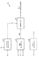
図1では、第1のエンコーダ10は、ディジタル形式の音声サンプルs(n)を受信し、サンプルs(n)をコード化して、伝送媒体12、すなわち通信チャンネル12上で第1のデコーダ14へ送る。デコーダ14はコード化された音声サンプルをデコードし、出力された音声信号SSYNTH(n)を合成する。反対方向で伝送するには、第2のエンコーダ16がディジタル形式の音声サンプルs(n)をコード化し、それを通信チャンネル18上で送る。第2のデコーダ20はコード化された音声サンプルを受信し、デコードし、合成された出力音声信号SSYNTH(n)を生成する。
In FIG. 1, a
音声サンプルs(n)は、この技術において知られている種々の方法、例えばパルスコード変調(pulse code modulation, PMC)、コンパンドされたμ法、すなわちA法(companded μ-law, or A-law)を含む方法にしたがって、ディジタル形式にされて量子化された音声信号を表わしている。この技術において知られているように、音声サンプルs(n)は、各々が所定数のディジタル形式の音声サンプルs(n)を含む入力データのフレームへ編成される。例示的な実施形態では、8キロヘルツのサンプリングレートが採用され、各20ミリ秒のフレームは160サンプルを含んでいる。別途記載する実施形態では、データ伝送レートはフレームごとに8キロビット秒(フルレート)から4キロビット秒(2分の1レート)、2キロビット秒(4分の1レート)、1キロビット秒(8分の1レート)へ変化することが好都合である。その代わりに、他のデータレートを使用してもよい。ここで使用されているように、“フルレート(full rate)”または“高レート(high rate)”という用語は、通常は、8キロビット秒以上のデータレートを指し、“2分の1レート”または“低レート”という用語は、通常は、4キロビット秒以下のデータレートを指す。比較的に少ない音声情報を含むフレームに対して、より低いビットレートを選択的に採用できるので、データ伝送レートを変化させることが好都合である。当業者によって理解されるように、他のサンプリングレート、フレームサイズ、およびデータ伝送レートを使用してもよい。 The audio sample s (n) can be obtained by various methods known in the art, such as pulse code modulation (PMC), the compounded μ-method, ie the A-law (companded μ-law, or A-law). ) Represents a speech signal that has been digitized and quantized according to a method including: As is known in the art, speech samples s (n) are organized into frames of input data, each containing a predetermined number of digitally formatted speech samples s (n). In the exemplary embodiment, a sampling rate of 8 kilohertz is employed and each 20 millisecond frame includes 160 samples. In the separately described embodiment, the data transmission rate is from 8 kilobit seconds (full rate) to 4 kilobit seconds (half rate), 2 kilobit seconds (quarter rate), 1 kilobit second (8 minutes) per frame. It is convenient to change to 1 rate). Instead, other data rates may be used. As used herein, the term “full rate” or “high rate” usually refers to a data rate of 8 kilobit seconds or more, “half rate” or The term “low rate” usually refers to a data rate of 4 kilobit seconds or less. It is advantageous to change the data transmission rate because a lower bit rate can be selectively employed for frames containing relatively little audio information. Other sampling rates, frame sizes, and data transmission rates may be used, as will be appreciated by those skilled in the art.
第1のエンコーダ10および第2のデコーダ20は共に第1の音声コーダ、すなわち音声コーデックを含む。同様に、第2のエンコーダ16および第1のデコーダ14は共に第2の音声コーダを含む。音声コーダはディジタル信号プロセッサ(digital signal processor, DSP)、特定用途向け集積回路(application-specific integrated circuit, ASIC)、離散的ゲート論理(discrete gate logic)、ファームウエア、または従来のプログラマブルソフトウエアモジュールおよびマイクロプロセッサで構成されていてもよいことが分かるであろう。ソフトウエアモジュールは、RAMメモリ、フラッシュメモリ、レジスタ、またはこの技術において知られている他の形態の書き込み可能な記憶媒体内にある。その代わりに、従来のプロセッサ、制御装置、または状態機械をマイクロプロセッサと置換してもよい。音声のコード化のために特別に設計されたASICの例は、本発明の譲受人に譲渡され、かつここでは参考文献として全面的に取り上げている米国特許第5,727,123号、および1994年2月16日に出願され、本発明の譲受人に譲渡され、かつここでは参考文献として全面的に取り上げている米国特許出願第08/197,417号(発明の名称:VOCODER ASIC)に記載されている。
Both the
1つの実施形態にしたがって、図2に示されているように、音声コーダ内で使用できるマルチモードの混合領域の線形予測(mixed-domain linear prediction, MDLP)エンコーダ100は、モード決定モジュール102、ピッチ推定モジュール104、線形予測(linear prediction, LP)解析モジュール106、LP解析フィルタ108、LP量子化モジュール110、およびMDLP残余エンコーダ112を含む。入力音声フレームs(n)は、モード決定モジュール102、ピッチ推定モジュール104、LP解析モジュール106、およびLP解析フィルタ108へ供給される。モード決定モジュール102は、各入力音声フレームs(n)の周期性および他の抽出パラメータ、例えばエネルギー、スペクトルチルト、ゼロ交差レート、などに基づいて、モード指標IMおよびモードMを生成する。周期性にしたがって音声フレームを分類する種々の方法は、米国特許出願第08/815,354号(発明の名称:METHOD AND APPARATUS FOR PERFORMING REDUCED RATE VARIABLE RATE VOCODING)に記載されており、これは1997年3月11日に出願され、本発明の譲受人に譲渡され、ここでは参考文献として全面的に取り上げている。このような方法は、米国電気通信工業会の業界暫定標準(Telecommunication Industry Association Industry Interim Standards)のTIA/EIA IS-127およびTIA/EIA IS-733にも採用されている。

MDLP残余エンコーダ112を除いて、図2のエンコーダ100および図3のデコーダ200の種々のモジュールの動作および構成はこの技術において知られており、上述の米国特許第5,414,796号およびLB. Rabiner & R.W. Schaferによる文献(Digital Processing of Speech Signals 396-453 (1978))に記載されている。
Except for the MDLP residual encoder 112, the operation and configuration of the various modules of the
1つの実施形態にしたがって、MDLPエンコーダ(図示されていない)は、図4のフローチャートに示したステップを実行する。MDLPエンコーダは、図2のMDLP残余エンコーダ112であってもよい。ステップ300では、MDLPエンコーダは、モードMがフルレート(full rate, FR)であるか、4分の1レート(quarter rate, QR)であるか、または8分の1レート(eighth rate, ER)であるかを検査する。モードMがFR、QR、またはERであるときは、MDLPエンコーダはステップ302へ進む。ステップ302では、MDLPエンコーダは対応するレート(Mの値に依存して−FR,QR、またはER)を残余指標IRへ適用する。時間領域のコード化は、FRモードでは高精度で高レートのコード化であり、かつCELPのコード化であることが好都合であるが、この時間領域のコード化は、LPの残余フレーム、またはその代わりに音声フレームへ適用される。次にフレームは(ディジタル対アナログ変換および変調を含む別の信号処理の後で)送られる。1つの実施形態では、フレームは、予測誤差を表わすLP残余フレームである。代わりの実施形態では、フレームは、音声サンプルを表わす音声フレームである。
According to one embodiment, an MDLP encoder (not shown) performs the steps shown in the flowchart of FIG. The MDLP encoder may be the MDLP residual encoder 112 of FIG. In
他方で、ステップ300では、モードMがFR、QR、またはERでなかったとき(すなわち、モードMが2分の1レート(half rate, HR)であるとき)、MDLPエンコーダはステップ304へ進む。ステップ304では、スペクトルのコード化、好ましくは高調波のコード化を2分の1のレートでLP残余、またはその代わりに音声信号へ適用する。次にMDLPエンコーダはステップ306へ進む。ステップ306では、コード化された音声をデコードして、それを元の入力フレームと比較することによって、ひずみ尺度Dを得る。次にMDLPエンコーダは、ステップ308へ進む。ステップ308では、ひずみ尺度Dは所定の閾値Tと比較される。ひずみ尺度Dが閾値Tよりも大きいときは、2分の1レートのスペクトル的にコード化されたフレームについて、対応する量子化されたパラメータが変調されて、送られる。他方で、ひずみ尺度Dが閾値T以下であるときは、MDLPエンコーダはステップ310へ進む。ステップ310では、デコードされたフレームは、この時間領域においてフルレートで再びコード化される。従来の高レートで高精度のコード化アルゴリズム、例えば好ましくはCELPのコード化を使用してもよい。次に、フレームと関係するFRモードの量子化されたパラメータが変調されて、送られる。
On the other hand, at
図5のフローチャートに示したように、次に1つの実施形態にしたがって閉ループのマルチモードのMDLPの音声コーダは、音声サンプルを処理して送る1組のステップにしたがう。ステップ400では、音声コーダは、連続するフレーム内の音声信号のディジタルサンプルを受信する。所与のフレームを受信すると、音声コーダはステップ402へ進む。ステップ402では、音声コーダはフレームのエネルギーを検出する。エネルギーはフレームの音声活動(speech activity)の尺度である。音声検出は、ディジタル形式の音声サンプルの振幅の平方を加算して、生成されたエネルギーを閾値と比較することによって行なわれる。1つの実施形態では、背景ノイズの変化レベルに基づいて閾値を採用する。例示的な可変閾値の音声活動検出器は、上述の米国特許第5,414,796号に記載されている。若干の無声音の音声は非常に低いエネルギーのサンプルであり、誤って背景ノイズとしてコード化されてしまうことがある。このようなことが発生するのを防ぐために、上述の米国特許第5,414,796号に記載されているように、低エネルギーサンプルのスペクトルのチルトを使用して、無声音の音声を背景ノイズと区別する。
As shown in the flowchart of FIG. 5, a closed-loop multi-mode MDLP speech coder then follows a set of steps for processing and sending speech samples according to one embodiment. In
フレームのエネルギーを検出した後で、音声コーダはステップ404へ進む。ステップ404では、音声コーダは、音声情報を含んでいるかについてフレームを分類するのに、検出されたフレームエネルギーが十分であるかどうかを判断する。検出されたフレームエネルギーが所定の閾値レベルよりも低いときは、音声コーダはステップ406へ進む。ステップ406では、音声コーダは背景ノイズ(すなわち、非音声、または黙音)としてフレームをコード化する。1つの実施形態では、背景ノイズのフレームは、8分の1レート、すなわち1キロビット秒でコード化される時間領域である。ステップ404では、検出されたフレームのエネルギーが所定の閾値レベル以上であるとき、フレームは音声として分類され、音声コーダはステップ408へ進む。
After detecting the energy of the frame, the speech coder proceeds to step 404. In step 404, the speech coder determines whether the detected frame energy is sufficient to classify the frame as containing speech information. If the detected frame energy is below a predetermined threshold level, the speech coder proceeds to step 406. In
ステップ408では、音声コーダは、フレームが周期的であるかどうかを判断する。周期性を判断する種々の既知の方法には、例えばゼロ交差の使用および正規化された自動相関関数(normalized autocorrelation function, NACF)の使用を含む。とくに、ゼロ交差およびNACFを使用して、周期性を検出することは、米国出願第08/815,354号(発明の名称:METHOD AND APPARATUS FOR PERFORMING REDUCED RATE VARIABLE RATE VOCODING)に記載されており、これは1997年3月11日に出願され、本発明の譲受人に譲渡され、ここでは参考文献として全面的に取り上げている。さらに加えて、無声音の音声から有声音の音声を区別するのに使用される上述の方法は、米国電気通信工業会の業界暫定標準(Telecommunication Industry Association Industry Interim Standards)のTIA/EIA IS-127およびTIA/EIA IS-733に採用されている。ステップ408においてフレームが周期的でないと判断されるとき、音声コーダはステップ410へ進む。ステップ410では、音声コーダは、フレームを無声音の音声としてコード化する。1つの実施形態では、無声音の音声フレームは、4分の1レート、すなわち2キロビット秒でコード化される時間領域である。ステップ408では、フレームが周期的であると判断されるとき、音声コーダはステップ412へ進む。
In
ステップ412では、音声コーダは、例えば上述の米国特許出願第08/815,354号に記載されているように、この技術において知られている周期性検出方法を使用して、フレームが十分に周期的であるかどうかを判断する。フレームが十分に周期性でないと判断されるときは、音声コーダはステップ414へ進む。ステップ414では、フレームは遷移音声(transition speech)(すなわち、無声音の音声から有声音の音声への遷移)として時間領域でコード化される。1つの実施形態では、遷移音声フレームはフルレート、すなわち8キロビット秒で時間領域でコード化される。
In
音声コーダは、ステップ412においてフレームが十分に周期的であると判断すると、ステップ416へ進む。ステップ416では、音声コーダは有声音の音声としてフレームをコード化する。1つの実施形態では、有声音の音声フレームは、とくに2分の1レート、すなわち4キロビット秒でスペクトル的にコード化される。図7を参照して別途記載するように、有声音の音声フレームは、高調波のコーダでスペクトル的にコード化されることが好都合である。その代わりに、他のスペクトルコーダは、この技術において知られているように、例えばシヌソイド変換コーダ(sinusoidal transmission coder)またはマルチバンド励起コーダ(multiband excitation coder)として使用できることが好都合である。次に音声コーダはステップ418へ進む。ステップ418では、音声コーダはコード化された有声音の音声フレームをデコードする。次に音声コーダはステップ420へ進む。ステップ420では、デコードされた有声音の音声フレームを、このフレームの対応する入力音声サンプルと比較して、合成された音声のひずみ尺度を得て、2分の1レートの有声音音声のスペクトルコード化モデルが許容限度内で動作しているかどうかを判断する。次に音声コーダはステップ422へ進む。
If the voice coder determines in
ステップ422では、音声コーダは、デコードされた有声音の音声フレームと、このフレームに対応する入力音声フレームとの誤差が所定の閾値より小さいかどうかを判断する。1つの実施形態では、この判断は、図6を参照して別途記載するやり方で行われる。コード化のひずみが所定の閾値よりも低いときは、音声コーダはステップ426へ進む。ステップ426では、音声コーダは、ステップ416のパラメータを使用して、フレームを有声音の音声として送る。ステップ422では、コード化のひずみが所定の閾値以上であるときは、音声コーダはステップ414へ進み、ステップ400において受信したディジタル形式の音声サンプルのフレームを遷移音声としてフルレートで時間領域でコード化する。
In
ステップ400ないし410は開ループのコード化決定モードを含むことに注目すべきである。他方で、ステップ412ないし426は閉ループのコード化決定モードを含む。 Note that steps 400 through 410 include an open loop coding decision mode. On the other hand, steps 412 to 426 include a closed loop coding decision mode.
1つの実施形態では、図6に示したように、閉ループのマルチモードのMDLPの音声コーダはアナログ対ディジタルコンバータ(analog-to-digital converter, A/D)500を含み、A/D500はフレームバッファ502に接続され、フレームバッファ502は制御プロセッサ504に接続される。エネルギー計算器506、有声音音声の検出器508、背景ノイズエンコーダ510、高レートの時間領域エンコーダ512、および低レートのスペクトルエンコーダ514は制御プロセッサ504へ接続される。スペクトルデコーダ516はスペクトルエンコーダ514に接続され、誤差計算器518はスペクトルデコーダ516および制御プロセッサ504へ接続される。閾値比較器520は、誤差計算器518および制御プロセッサ504へ接続される。バッファ522はスペクトルエンコーダ514、スペクトルデコーダ516、および閾値比較器520へ接続される。
In one embodiment, as shown in FIG. 6, the closed-loop multi-mode MDLP speech coder includes an analog-to-digital converter (A / D) 500, where the A /
図6の実施形態では、音声コーダの構成要素は、音声コーダ内にファームウエアまたは他のソフトウエア駆動モジュールとして構成されていることが好都合であり、音声コーダ自身はDSPまたはASIC内にあることが好都合である。当業者には、音声コーダの構成要素は、多数の他の既知のやり方で同様に適切に構成できることが分かるであろう。制御プロセッサ504はマイクロプロセッサであることが好都合であるが、制御装置、状態機械、または離散的論理と共に構成されていてもよい。
In the embodiment of FIG. 6, the components of the voice coder are conveniently configured as firmware or other software-driven modules within the voice coder, and the voice coder itself may be within a DSP or ASIC. Convenient. Those skilled in the art will appreciate that the components of the speech coder can be similarly configured in a number of other known ways as well. The
図6のマルチモードのコーダでは、音声信号はA/D500へ供給される。A/D500はアナログ信号をディジタル形式の音声サンプルS(n)へ変換する。ディジタル形式の音声サンプルは、フレームバッファ502へ供給される。制御プロセッサ504は、フレームバッファ502からディジタル形式の音声サンプルを得て、それらをエネルギー計算器506へ供給する。エネルギー計算器506は、次の式にしたがって音声サンプルのエネルギーEを計算する:
なお、フレームは20ミリ秒長であり、サンプリングレートは8キロヘルツである。計算されたエネルギーEは制御プロセッサ504へ送られる。
The frame is 20 milliseconds long and the sampling rate is 8 kilohertz. The calculated energy E is sent to the
制御プロセッサ504は、計算された音声エネルギーを音声活動(speech activity)の閾値と比較する。計算されたエネルギーが音声活動の閾値よりも小さいときは、制御プロセッサ504はディジタル形式の音声サンプルをフレームバッファ502から背景ノイズエンコーダ510へ送る。背景ノイズエンコーダ510は、背景ノイズの推定値を保持するために必要な最少数のビットを使用して、フレームをコード化する。
The
計算されたエネルギーが音声活動の閾値以上であるときは、制御プロセッサ504はディジタル形式の音声サンプルをフレームバッファ502から有声音音声の検出器508へ方向付ける。有声音音声の検出器508は、音声フレームの周期性が、低ビットレートのスペクトルのコード化を使用して効率的なコード化を可能にするかどうかを判断する。音声フレーム内の周期性のレベルを判断する方法は、この技術においてよく知られており、例えば正規化された自動相関関数(normalized autocorrelation function, NACF)およびゼロ交差の使用を含む。これらの方法および他の方法は、上述の米国特許出願第08/815,354号に記載されている。
When the calculated energy is greater than or equal to the voice activity threshold, the
有声音音声の検出器508は、スペクトルエンコーダ514が効率的にコード化するのに十分な周期性をもつ音声を音声フレームが含んでいるかどうかを示す信号を制御プロセッサ504へ供給する。有声音音声の検出器508が、音声フレームが十分な周期性を欠いていると判断するとき、制御プロセッサ504はディジタル形式の音声サンプルを高レートのエンコーダ512へ方向付け、エンコーダ512は所定の最大データレートで音声を時間領域でコード化する。1つの実施形態では、所定の最大データレートは8キロビット秒であり、高レートのエンコーダ512はCELPのコーダである。
有声音音声の検出器508が最初に、音声信号が、スペクトルエンコーダ514が効率的にコード化するのに十分な周期性をもつと判断するとき、制御プロセッサ504は、フレームバッファ502からスペクトルエンコーダ514へディジタル形式の音声サンプルを方向付ける。例示的なスペクトルエンコーダは、図7を参照して別途詳しく記載する。
計算されたMSEが許容範囲内であるときは、閾値比較器520は信号をバッファ522へ供給し、スペクトル的にコード化されたデータは音声コーダから出力される。他方で、MSEが許容限界内でないときは、閾値の比較器520は信号を制御プロセッサ504へ送り、制御プロセッサ504はディジタル形式のサンプルをフレームバッファ502から高レートの時間領域のエンコーダ512へ方向付ける。時間領域のエンコーダ512は、所定の最大レートでフレームをコード化し、バッファ522の内容は捨てられる。
When the calculated MSE is within an acceptable range, the threshold comparator 520 provides a signal to the
図6の実施形態では、採用されたスペクトルのコード化のタイプは高調波のコード化であり、これについては図7を参照して別途記載するが、代わりの実施形態では、シヌソイド変換のコード化またはマルチバンド励起のコード化のような、スペクトルのコード化のタイプであってもよい。マルチバンド励起のコード化の使用は、米国特許第5,195,166号に記載されており、シヌソイド変換のコード化の使用は、例えば米国特許第4,865,068号に記載されている。 In the embodiment of FIG. 6, the type of spectral encoding employed is harmonic encoding, which will be described separately with reference to FIG. 7, but in an alternative embodiment, encoding of the sinusoid transform Or it may be a type of spectral coding, such as multi-band excitation coding. The use of multiband excitation coding is described in US Pat. No. 5,195,166, and the use of sinusoidal transform coding is described, for example, in US Pat. No. 4,865,068.
遷移フレーム、および位相ひずみ閾値が周期性パラメータ以下である有声音フレームでは、図6のマルチモードコーダはフルレート、すなわち8キロビット秒で、高レートの時間領域のコーダ512によって、CELPのコード化を採用することが好都合である。その代わりに、このようなフレームに対して、他の既知の形態の高レートの時間領域のコード化を使用してもよい。したがって、遷移フレーム(および十分に周期的でない有声音フレーム)は高い精度でコード化され、入力および出力における波形は適切に整合し、位相情報は適切に保持される。1つの実施形態では、マルチモードコーダは、閾値比較器520の判断と無関係に、閾値が周期性の尺度を越えている所定数の連続する有声音フレームを処理した後で、各フレームごとに2分の1レートのスペクトルのコード化からフルレートのCELPのコード化へスイッチする。
For transitional frames and voiced frames whose phase distortion threshold is less than or equal to the periodicity parameter, the multimode coder of FIG. 6 employs CELP coding with a high rate
制御プロセッサ504に関連して、エネルギー計算器506および有声音音声の検出器508は開ループのコード化決定を含むことに注意すべきである。対照的に、制御プロセッサ504に関連して、スペクトルエンコーダ514、スペクトルデコーダ516、誤差計算器518、閾値比較器520、およびバッファ522は閉ループのコード化決定を含む。
It should be noted that in connection with
図7を参照して記載した1つの実施形態では、スペクトルのコード化、好ましくは高調波のコード化を使用して、低ビットレートで十分に周期的な有声音フレームをコード化する。スペクトルコーダは、一般的に、周波数領域内の各音声フレームをモデル化してコード化することによって知覚的に重要なやり方で音声スペクトル特性の時間にしたがう漸進的変化(time-evolution)を保持することを試みるアルゴリズムとして規定される。このようなアルゴリズムの本質的な部分では、(1)スペクトルの解析またはパラメータの推定、(2)パラメータの量子化、(3)出力された音声波形とデコードされたパラメータとの合成を行う。したがって、1組のスペクトルパラメータをもつ短期間の音声スペクトルの重要な特性を保持し、デコードされたスペクトルパラメータを使用して、出力音声を合成することを目的とする。通常は、出力音声は、シヌソイドの重み付けされた和として合成される。シヌソイドの振幅、周波数、および位相は、解析中に推定されるスペクトルパラメータである。 In one embodiment described with reference to FIG. 7, spectral encoding, preferably harmonic encoding, is used to encode a sufficiently periodic voiced sound frame at a low bit rate. Spectral coders generally maintain time-evolution over time of speech spectral characteristics in a perceptually important manner by modeling and coding each speech frame in the frequency domain. Specified as an algorithm that tries to The essential parts of such an algorithm are (1) spectrum analysis or parameter estimation, (2) parameter quantization, and (3) synthesis of the output speech waveform and decoded parameters. Accordingly, it is intended to preserve the important characteristics of the short-term speech spectrum with a set of spectral parameters and to synthesize the output speech using the decoded spectral parameters. Normally, the output speech is synthesized as a weighted sum of sinusoids. The sinusoid amplitude, frequency, and phase are spectral parameters estimated during analysis.
“合成による解析”はCELPのコード化においてよく知られた技術であるが、この技術はスペクトルのコード化には利用されていない。合成による解析がスペクトルコーダに適用されない主な理由は、初期位相の情報の損失によって、音声モデルが知覚の観点から適切に機能していても、合成された音声の平均二乗エネルギー(mean square energy, MSE)が高いからである。したがって、初期位相を正確に生成すると、音声サンプルと再構成された音声とを直接に比較して、音声モデルが音声フレームを正確にコード化しているかどうかを判断できるといった別の長所がある。 “Analysis by synthesis” is a well-known technique in CELP coding, but this technique has not been used for spectral coding. The main reason that synthesis analysis does not apply to spectrum coders is that the loss of the initial phase information causes the mean square energy, even if the speech model is functioning properly from a perceptual point of view. This is because MSE) is high. Thus, generating the initial phase correctly has another advantage in that it can directly compare the speech samples and the reconstructed speech to determine whether the speech model accurately encodes the speech frame.
スペクトルのコード化では、出力された音声フレームは次に示すように合成することができる: S[n]=Sv[n]+Suv[n],n=1,2,...,N,なお、Nは1フレーム当りのサンプル数であり、SvおよびSuvは、それぞれ有声音成分および無声音成分である。シヌソイド和合成プロセス(sum-of-sinusoid synthesis process)は次の式に示すように有声音成分を生成する:
振幅、周波数、および位相パラメータは、スペクトル解析プロセスによって入力フレームの短期間のスペクトルから推定される。無声音成分は、単一のシヌソイド和合成において有声音部分と一緒に生成されるか、または専用の無声音合成プロセスによって別々に計算され、Svへ再び加えられる。 Amplitude, frequency, and phase parameters are estimated from the short-term spectrum of the input frame by a spectral analysis process. Unvoiced components, either generated along with the voiced part in a single sinusoid sum synthetic or computed separately by a dedicated unvoiced synthesis process is added back to S v.
図7の実施形態では、高調波コーダと呼ばれる特定のタイプのスペクトルコーダを使用して、低ビットレートで十分に周期的な有声音フレームをスペクトル的にコード化する。高調波のコーダは、シヌソイド和としてフレームを特徴付け、フレームの小さいセグメントを解析する。シヌソイド和の中の各シヌソイドは、フレームのピッチF0の整数倍の周波数をもつ。代わりの実施形態では、高調波のコーダ以外の特定のタイプのスペクトルコーダを使用し、各フレームに対するシヌソイド周波数は、0ないし2πの1組の実数から得られる。図7の実施形態では、和の中の各シヌソイドの振幅および位相が選択されることが好都合であり、その結果、図8のグラフによって示したように、和は1期間において信号と最良に整合する。高調波のコーダは一般的に外部の分類を採用し、各入力音声フレームは有声音または無声音として表示する。有声音フレームでは、シヌソイドの周波数は推定されたピッチ(F0)の高調波に制限され、すなわちfk=kF0である。無声音の音声では、短期間のスペクトルのピークを使用して、シヌソイドを判断する。次の式に示すように、振幅および位相が補間されて、フレームにおいて漸進的変化をまねる:
シヌソイドごとに送られるパラメータは振幅および周波数である。位相は送られないが、その代わりに、例えば準位相モデル(quadratic phase model)、または位相の従来の多項式表現を含むいくつかの既知の技術にしたがってモデル化される。 The parameters sent for each sinusoid are amplitude and frequency. The phase is not sent, but instead is modeled according to several known techniques including, for example, a quadratic phase model, or a conventional polynomial representation of the phase.
図7に示されているように、高調波コーダはピッチ抽出器600を含み、ピッチ抽出器600はウインドウ処理論理602へ接続され、ウインドウ処理論理602は離散フーリエ変換(Discrete Fourier Transform, DFT)、および高調波解析論理604へ接続される。入力として音声サンプルS(n)を受信するピッチ抽出器600はは、DFTおよび高調波解析論理604へも接続される。DFTおよび高調波解析論理604は、残余エンコーダ606へ接続される。ピッチ抽出器600、DFTおよび高調波解析論理604、並びに残余エンコーダ606は、パラメータ量子化器608へそれぞれ接続される。パラメータ量子化器608はチャンネルエンコーダ610へ接続され、チャンネルエンコーダ610は送信機612へ接続される。送信機612は、例えば、符号分割多重アクセス(code division multiple access, CDMA)のような標準の無線周波数(radio-frequency, RF)のインターフェイスによって空中インターフェイス(over-the-air interface)上で、受信機614へ接続される。受信機614はチャンネルデコーダ616へ接続され、チャンネルデコーダ616は非量子化器618へ接続される。非量子化器618はシヌソイド和音声合成器620へ接続される。シヌソイド和音声合成器620へさらに接続されるのは位相推定器622であり、位相推定器622は入力として前フレーム情報を受信する。シヌソイド和音声合成器620は合成された音声出力SSYNTH(n)を生成するように構成されている。
As shown in FIG. 7, the harmonic coder includes a
ピッチ抽出器600、ウインドウ処理論理602、DTFおよび高調波解析論理604、残余エンコーダ606、パラメータ量子化器608、チャンネルエンコーダ610、チャンネルデコーダ616、非量子化器618、シヌソイド和音声合成器620、並びに位相推定器622は、例えばファームウエアまたはソフトウエアモジュールを含む、当業者によく知られている種々の異なるやり方で構成することができる。送信機612および受信機614は、当業者には知られている対応する標準のRFの構成要素で実行されていてもよい。
図7の高調波コーダでは、入力サンプルS(n)はピッチ抽出器600によって受信され、ピッチ抽出器600はピッチ周波数情報F0を抽出する。次にサンプルは、ウインドウ処理論理602によって適切なウインドウ処理関数によって乗算され、音声フレームの小さいセグメントの解析を可能にしている。ピッチ抽出器600によって供給されるピッチ情報を使用して、DFTおよび高調波解析論理604はサンプルのDFTを計算して、複合のスペクトル点を生成し、この複合のスペクトル点から、図8のグラフによって示されているように、高調波の振幅AIを抽出し、なお図8において、Lは高調波の合計数を示している。DFTは残余エンコーダ606へ供給され、残余エンコーダ606は音声情報(voicing information)Vcを抽出する。
The harmonic coder of FIG. 7, input samples S (n) is received by the
Vcパラメータは、図8に示されているように、周波数軸上の点を示し、Vcがより高くなると、スペクトルは無声音の音声信号の特性を示し、最早高調波ではなくなることに注意すべきである。対照的に、点Vcより低くなると、スペクトルは高調波であり、有声音の音声の特性を示す。 The V c parameter indicates a point on the frequency axis as shown in FIG. 8, and note that as V c becomes higher, the spectrum is characteristic of an unvoiced speech signal and is no longer a harmonic. Should. In contrast, below the point V c , the spectrum is harmonic and exhibits voiced voice characteristics.
AI,F0,およびVcの成分は、パラメータ量子化器608へ供給され、パラメータ量子化器608では情報を量子化する。量子化された情報はパケットの形態でチャンネルエンコーダ610へ供給され、チャンネルエンコーダ610では、例えばハーフレート、すなわち4キロビット秒のような低ビットレートでパケットを量子化する。パケットは送信機612へ供給され、送信機612はパケットを変調して、生成された信号を受信機614へ空中で(over the air)送る。受信機614は信号を受信して、復調して、コード化されたパケットをチャンネルデコーダ616へ送る。チャンネルデコーダ616はパケットをデコードして、デコードされたパケットを非量子化器618へ供給する。非量子化器618は情報を非量子化する。情報はシヌソイド和音声合成器620へ供給される。
The components of A I , F 0 , and V c are supplied to the
シヌソイド和音声合成器620は、S[n]についての上述の式にしたがって短期間の音声スペクトルをモデル化する複数のシヌソイドのモデリングを合成するように構成されている。シヌソイドfkの周波数は、基本周波数F0の倍数または高調波であり、準周期的な(すなわち、遷移の)有声音の音声セグメントに対するピッチの周期性をもつ周波数である。
The sinusoidal
さらに加えて、シヌソイド和の音声合成器620は位相推定器622から位相情報を受信する。位相推定器622は前フレームの情報、すなわち直前フレームについてのAI,F0,およびVcのパラメータを受信する。位相推定器622は、前フレームの再構成されたNのサンプルも受信し、なおNはフレーム長(すなわち、Nは1フレーム当りのサンプル数)である。位相推定器622は、前フレームの情報に基づいて、フレームの初期位相を判断する。初期位相の判断は、シヌソイド和の音声合成器620へ供給される。現在のフレームに関する情報と、過去のフレーム情報に基いて位相推定器622によって行なわれた初期位相の計算とを基にして、シヌソイド和音声合成器620は上述のように音声フレームを生成する。
In addition, the sinusoidal
既に記載したように、高調波のコーダは、前フレームの情報を使用して、位相がフレームからフレームへ線形に変化することを予測することによって、音声フレームを合成、すなわち再構成する。上述の合成モデルは、一般的に準位相モデルと呼ばれており、このような合成モデルでは、係数B3(k)は、現在の有声音フレームの初期位相が合成されていることを表わしている。位相を判断するとき、従来の高調波のコーダは初期位相をゼロに設定するか、または初期位相値をランダムに、あるいは疑似ランダム生成方法を使用して生成する。位相をより正確に予測するために、位相推定器622は、直前のフレームが有声音の音声フレーム(すなわち、十分に周期的なフレーム)であるか、または遷移音声フレームであるかに依存して、初期位相を判断するための2つの可能な方法の一方を使用する。前フレームが有声音の音声フレームであったときは、このフレームの推定された最終位相値は、現在のフレームの初期位相値として使用される。他方で、前フレームが遷移フレームとして分類されたときは、現在のフレームの初期位相値は、前フレームのスペクトルから得られ、これは前フレームのデコーダ出力のDFTを行なうことによって得られる。したがって位相推定器622は、(遷移フレームである前フレームがフルレートで処理されたので)既に使用可能である正確な位相情報を使用できる。
As already described, the harmonic coder uses the previous frame information to synthesize or reconstruct the speech frame by predicting that the phase will change linearly from frame to frame. The above synthesis model is generally called a quasi-phase model, and in such a synthesis model, the coefficient B 3 (k) indicates that the initial phase of the current voiced sound frame is synthesized. Yes. When determining the phase, a conventional harmonic coder sets the initial phase to zero, or generates the initial phase value randomly or using a pseudo-random generation method. To more accurately predict the phase, the
1つの実施形態では、閉ループのマルチモードのMDLPの音声コーダは、図9のフローチャート内に示されている音声処理ステップにしたがう。音声コーダは、最も適切なコード化モードを選択することによって、各入力音声フレームのLPの残余をコード化する。一定のモードは時間領域内でLPの残余、すなわち音声の残余をコード化し、一方で他のモードは周波数領域内でLPの残余、すなわち音声の残余を表わす。モードの組には、遷移フレームに対するフルレートの時間領域(Tモード);有声音フレームに対する2分の1レートの周波数領域(Vモード);無声音フレームに対する4分の1レートの時間領域(Uモード);およびノイズフレームに対する8分の1レートの時間領域(Nモード)がある。 In one embodiment, a closed loop multi-mode MDLP speech coder follows the speech processing steps shown in the flowchart of FIG. The speech coder encodes the LP remainder of each input speech frame by selecting the most appropriate coding mode. Certain modes encode LP residuals, i.e. speech residuals, in the time domain, while other modes represent LP residuals, i.e. speech residuals, in the frequency domain. Mode set includes full rate time domain for transition frames (T mode); half rate frequency domain for voiced frames (V mode); quarter rate time domain for unvoiced frames (U mode) And there is a 1/8 rate time domain (N mode) for noise frames.
当業者には、図9に示したステップにしたがうことによって、音声信号または対応するLPの残余がコード化されることが分かるであろう。ノイズ、無声音、遷移、および有声音の音声の波形特性は、図10aのグラフにおいて時間関数として参照することができる。ノイズ、無声音、遷移、および有声音のLPの残余の波形特性は、図10bのグラフにおいて時間関数として参照することができる。 Those skilled in the art will appreciate that following the steps shown in FIG. 9 encodes the speech signal or the corresponding LP residue. The waveform characteristics of noise, unvoiced sounds, transitions, and voiced sounds can be referenced as a function of time in the graph of FIG. 10a. The residual waveform characteristics of the noise, unvoiced, transition, and voiced LPs can be referenced as a function of time in the graph of FIG. 10b.
ステップ700では、4つのモード(T、V、U,またはN)の何れか1つに関して、開ループのモード決定を行って、入力音声の残余S(n)へ適用する。Tモードが適用されるときは、ステップ702では、時間領域においてTモード、すなわちフルレートで音声の残余が処理される。Uモードが適用されるときは、ステップ704で、時間領域においてUモード、すなわち4分の1レートで音声の残余が処理される。Nモードが適用されるときは、ステップ706では、時間領域においてNモード、すなわち8分の1レートで音声の残余が処理される。Vモードが適用されるときは、ステップ708では、周波数領域においてVモードで、すなわち2分の1レートで音声の残余が処理される。
In
ステップ710では、ステップ708でコード化された音声がデコードされ、入力音声の残余S(n)と比較され、性能尺度Dが計算される。ステップ712では、性能尺度Dが所定の閾値Tと比較される。性能尺度Dが閾値T以上であるときは、ステップ714では、ステップ708においてスペクトル的にコード化された音声の残余は送信を許可される。他方では、性能尺度Dが閾値Tよりも小さいときは、ステップ716では、入力音声の残余S(n)はTモードで処理される。別の実施形態では、性能尺度は計算されず、閾値は規定されない。その代わりに、所定数の音声残余フレームがVモードで処理された後で、次のフレームはTモードで処理される。
In
図9に示した決定のステップでは、高ビットレートのTモードを必要なときだけ使用して、より低いビットレートのVモードで有声音の音声セグメントの周期性を活用することができ、一方でVモードが適切に実行されないときは、フルレートにスイッチすることによって品質の低下を防ぐことが好都合である。したがって、フルレートの音声品質に近づく非常に高い音声品質を、フルレートよりも相当に低い平均レートで生成することができる。さらに、選択された性能尺度および選ばれた閾値によって、目標の音声品質を制御することができる。 In the decision step shown in FIG. 9, the high bit rate T mode can be used only when needed to take advantage of the periodicity of voiced speech segments in the lower bit rate V mode, while When V mode is not performed properly, it is advantageous to prevent quality degradation by switching to full rate. Thus, very high voice quality approaching full rate voice quality can be generated at an average rate substantially lower than the full rate. Furthermore, the target voice quality can be controlled by the selected performance measure and the selected threshold.
Tモードへの“更新”は、モデル位相追跡を入力音声の位相追跡の近くに維持することによって、後でVモードを適用する動作を向上することができる。Vモードの性能が不適切であるときは、ステップ710および712の閉ループの性能検査はTモードへスイッチし、初期位相値を“リフレッシュ”して、モデルの位相追跡を元の入力音声位相追跡に再び近付けることによって、次のVモードの処理の性能を向上することができる。例えば、図11aないしcのグラフに示したように、開始から5番目のフレームは、使用されているPSNRのひずみ尺度によって証明されているように、Vモードで適切に働かない。その結果、閉ループの決定および更新がないときは、モデル化された位相追跡は元の入力音声位相追跡から相当に外れ、図11cに示したように、PSNRを相当に劣化する。さらに、Vモードで処理される次のフレームの性能は劣化する。しかしながら、閉ループの決定のもとでは、5番目のフレームは、図11aに示したように、Tモードの処理へスイッチされる。5番目のフレームの性能は、図11bに示したように、PSNRにおける向上によって証明されているように、更新によって相当に向上する。さらに加えて、Vモードのもとで処理される次のフレームの性能も向上する。
“Updating” to the T mode can improve the operation of applying the V mode later by keeping the model phase tracking close to the phase tracking of the input speech. When the V-mode performance is inadequate, the closed-loop performance check in
図9に示した決定のステップでは、非常に正確な初期位相推定値を与えることによって、Vモードの表現品質を向上し、生成されたVモードの合成された音声の残余信号は元の入力音声の残余S(n)と正確に時間的に整合することを保証する。最初のVモードで処理された音声の残余セグメントにおける初期位相は、次に示すやり方で直前のデコードされたフレームから求められる。各高調波では、前フレームがVモードで処理されたときは、初期位相は前フレームの推定された最終位相に等しく設定される。各高調波では、前フレームがTモードで処理されたときは、初期位相は前フレームの実際の高調波の位相に等しく設定される。前フレームの実際の高調波の位相は、全ての前フレームを使用して過去のデコードされた残余のDFTをとることによって求められる。その代わりに、前フレームの実際の高調波の位相は、前フレームの種々のピッチ期間を処理することによって、ピッチが同期するやり方で、過去のデコードされたフレームのDFTをとることによって求められる。 The decision step shown in FIG. 9 improves the V-mode representation quality by giving a very accurate initial phase estimate, and the generated V-mode synthesized speech residual signal is the original input speech. It is guaranteed to be exactly in time alignment with the remaining S (n). The initial phase in the remaining segment of speech processed in the first V mode is determined from the previous decoded frame in the following manner. At each harmonic, when the previous frame is processed in V mode, the initial phase is set equal to the estimated final phase of the previous frame. For each harmonic, when the previous frame is processed in T mode, the initial phase is set equal to the phase of the actual harmonic of the previous frame. The phase of the actual harmonics of the previous frame is determined by taking the past decoded residual DFT using all previous frames. Instead, the phase of the actual harmonics of the previous frame is determined by taking the DFT of the previous decoded frame in a pitch-synchronized manner by processing the various pitch periods of the previous frame.
本明細書では、斬新な閉ループのマルチモードの混合領域の線形予測(mixed-domain linear prediction, MDLP)の音声コーダを記載した。当業者には、ここに開示した実施形態に関係して記載した種々の例示的な論理ブロックおよびアルゴリズムのステップが、ディジタル信号プロセッサ(digital signal processor, DSP)、特定用途向け集積回路(application specific integrated circuit, ASIC)、離散的ゲートまたはトランジスタ論理、例えばレジスタおよびFIFOのような離散的ハードウエア構成要素、1組のファームウエア命令を実行するプロセッサ、または従来のプログラマブルソフトウエアモジュールおよびプロセッサで構成または実行できることが分かるであろう。プロセッサは、マイクロプロセッサであることが好都合であるが、その代わりに従来のプロセッサ、制御装置、マイクロプロセッサ、または状態機械であってもよい。ソフトウエアモジュールは、RAMメモリ、フラッシュメモリ、レジスタ、またはこの技術において知られている他の形態の書き込み可能な記憶媒体内にあってもよい。当業者にはさらに、上述の記述全体で参照したデータ、命令、コマンド、情報、信号、ビット、符号、およびチップが、電圧、電流、電磁波、磁界または磁粒、光の範囲または粒子(optical field or particles)、あるいはその組み合わせによって都合よく表わされることが分かるであろう。 The present description describes a novel closed-loop multi-mode mixed-domain linear prediction (MDLP) speech coder. Those skilled in the art will recognize that the various exemplary logic blocks and algorithm steps described in connection with the embodiments disclosed herein are digital signal processors (DSPs), application specific integrated circuits. circuit, ASIC), discrete gate or transistor logic, eg, discrete hardware components such as registers and FIFOs, a processor that executes a set of firmware instructions, or a conventional programmable software module and processor. You will see that you can. The processor is conveniently a microprocessor, but may alternatively be a conventional processor, controller, microprocessor, or state machine. The software modules may be in RAM memory, flash memory, registers, or other forms of writable storage media known in the art. Those skilled in the art will further understand that the data, instructions, commands, information, signals, bits, symbols, and chips referred to throughout the above description are voltage, current, electromagnetic, magnetic or magnetic particles, optical ranges or particles. or particles), or a combination thereof, will be conveniently represented.
本明細書では、本発明の好ましい実施形態を示し、記載した。しかしながら、当業者の一人には、ここに記載した実施形態に対して、本発明の意図または技術的範囲から逸脱せずに多数の変更を加えられることが分かるであろう。したがって、本発明は、特許請求項にしたがうことを除いて制限されない。 Herein, preferred embodiments of the present invention have been shown and described. However, one of ordinary skill in the art appreciates that many modifications can be made to the embodiments described herein without departing from the spirit or scope of the invention. Accordingly, the invention is not limited except as according to the claims.
Claims (26)
コーダに接続され、かつ音声プロセッサによって処理されるフレーム内容に基づいてコーダのコード化モードを選択するように構成されている閉ループのモード選択デバイスとを含むマルチモードの混合領域の音声プロセッサ。 A coder having at least one time domain coding mode and at least one frequency domain coding mode;
A multi-mode mixed domain speech processor, comprising: a closed-loop mode selection device connected to the coder and configured to select a coding mode of the coder based on frame content processed by the speech processor.
開ループのコード化モード選択プロセスを各連続する入力フレームへ適用して、入力フレームの音声内容に基づいて、時間領域コード化モードか、または周波数領域コード化モードの何れかを選択するステップと、
入力フレームの音声内容が定常状態の有声音の音声を示すときは、入力フレームを周波数領域でコード化するステップと、
入力フレームの音声内容が定常状態の有声音の音声以外のものを示すときは、入力フレームを時間領域でコード化するステップと、
周波数領域でコード化されたフレームと入力フレームとを比較して、性能尺度を求めるステップと、
性能尺度が所定の閾値よりも低いときは、入力フレームを時間領域でコード化するステップとを含むフレームを処理する方法。 A method of processing a frame,
Applying an open-loop coding mode selection process to each successive input frame to select either a time-domain coding mode or a frequency-domain coding mode based on the audio content of the input frame;
Encoding the input frame in the frequency domain when the audio content of the input frame indicates a voiced voice in a steady state;
Encoding the input frame in the time domain when the audio content of the input frame indicates something other than steady-state voiced speech;
Comparing the frequency-coded frame with the input frame to determine a performance measure;
Encoding the input frame in the time domain when the performance measure is below a predetermined threshold.
開ループのコード化モード選択プロセスを入力フレームへ適用して、入力フレームの音声内容に基づいて、時間領域コード化モードか、または周波数領域コード化モードの何れかを選択する手段と、
入力フレームの音声内容が定常状態の有声音の音声を示すときは、入力フレームを周波数領域でコード化する手段と、
入力フレームの音声内容が定常状態の有声音の音声以外のものを示すときは、入力フレームを時間領域でコード化する手段と、
周波数領域でコード化されたフレームと入力フレームとを比較して、性能尺度を求める手段と、
性能尺度が所定の閾値よりも低いときは、入力フレームを時間領域でコード化する手段とを含むマルチモードの混合領域の音声プロセッサ。 A multi-mode mixed-domain audio processor,
Means for applying an open-loop coding mode selection process to the input frame to select either a time-domain coding mode or a frequency-domain coding mode based on the audio content of the input frame;
Means for encoding the input frame in the frequency domain when the audio content of the input frame indicates a voiced voice in a steady state;
Means for encoding the input frame in the time domain when the audio content of the input frame indicates something other than a steady-state voiced sound;
Means for comparing a frame coded in the frequency domain with an input frame to obtain a performance measure;
A multi-mode mixed domain speech processor including means for encoding the input frame in the time domain when the performance measure is below a predetermined threshold.
Priority Applications (1)
| Application Number | Priority Date | Filing Date | Title |
|---|---|---|---|
| JP2010249991A JP2011090311A (en) | 2010-11-08 | 2010-11-08 | Linear prediction voice coder in mixed domain of multimode of closed loop |
Applications Claiming Priority (1)
| Application Number | Priority Date | Filing Date | Title |
|---|---|---|---|
| JP2010249991A JP2011090311A (en) | 2010-11-08 | 2010-11-08 | Linear prediction voice coder in mixed domain of multimode of closed loop |
Related Parent Applications (1)
| Application Number | Title | Priority Date | Filing Date |
|---|---|---|---|
| JP2001564148A Division JP4907826B2 (en) | 2000-02-29 | 2000-02-29 | Closed-loop multimode mixed-domain linear predictive speech coder |
Publications (2)
| Publication Number | Publication Date |
|---|---|
| JP2011090311A true JP2011090311A (en) | 2011-05-06 |
| JP2011090311A5 JP2011090311A5 (en) | 2011-06-16 |
Family
ID=44108560
Family Applications (1)
| Application Number | Title | Priority Date | Filing Date |
|---|---|---|---|
| JP2010249991A Pending JP2011090311A (en) | 2010-11-08 | 2010-11-08 | Linear prediction voice coder in mixed domain of multimode of closed loop |
Country Status (1)
| Country | Link |
|---|---|
| JP (1) | JP2011090311A (en) |
Cited By (1)
| Publication number | Priority date | Publication date | Assignee | Title |
|---|---|---|---|---|
| CN112735452A (en) * | 2020-12-31 | 2021-04-30 | 北京百瑞互联技术有限公司 | Coding method, device, storage medium and equipment for realizing ultra-low coding rate |
-
2010
- 2010-11-08 JP JP2010249991A patent/JP2011090311A/en active Pending
Cited By (2)
| Publication number | Priority date | Publication date | Assignee | Title |
|---|---|---|---|---|
| CN112735452A (en) * | 2020-12-31 | 2021-04-30 | 北京百瑞互联技术有限公司 | Coding method, device, storage medium and equipment for realizing ultra-low coding rate |
| CN112735452B (en) * | 2020-12-31 | 2023-03-21 | 北京百瑞互联技术有限公司 | Coding method, device, storage medium and equipment for realizing ultra-low coding rate |
Similar Documents
| Publication | Publication Date | Title |
|---|---|---|
| JP4907826B2 (en) | Closed-loop multimode mixed-domain linear predictive speech coder | |
| US6640209B1 (en) | Closed-loop multimode mixed-domain linear prediction (MDLP) speech coder | |
| US6584438B1 (en) | Frame erasure compensation method in a variable rate speech coder | |
| KR100895589B1 (en) | Method and apparatus for robust speech classification | |
| EP1279167B1 (en) | Method and apparatus for predictively quantizing voiced speech | |
| US8990074B2 (en) | Noise-robust speech coding mode classification | |
| US8346544B2 (en) | Selection of encoding modes and/or encoding rates for speech compression with closed loop re-decision | |
| US8090573B2 (en) | Selection of encoding modes and/or encoding rates for speech compression with open loop re-decision | |
| KR100827896B1 (en) | A predictive speech coder using coding scheme selection patterns to reduce sensitivity to frame errors | |
| KR100700857B1 (en) | Multipulse interpolative coding of transition speech frames | |
| US7085712B2 (en) | Method and apparatus for subsampling phase spectrum information | |
| US6449592B1 (en) | Method and apparatus for tracking the phase of a quasi-periodic signal | |
| JP4567289B2 (en) | Method and apparatus for tracking the phase of a quasi-periodic signal | |
| JP2011090311A (en) | Linear prediction voice coder in mixed domain of multimode of closed loop |
Legal Events
| Date | Code | Title | Description |
|---|---|---|---|
| A521 | Request for written amendment filed |
Free format text: JAPANESE INTERMEDIATE CODE: A523 Effective date: 20110411 |
|
| A131 | Notification of reasons for refusal |
Free format text: JAPANESE INTERMEDIATE CODE: A131 Effective date: 20120619 |
|
| A601 | Written request for extension of time |
Free format text: JAPANESE INTERMEDIATE CODE: A601 Effective date: 20120919 |
|
| A602 | Written permission of extension of time |
Free format text: JAPANESE INTERMEDIATE CODE: A602 Effective date: 20120924 |
|
| A521 | Request for written amendment filed |
Free format text: JAPANESE INTERMEDIATE CODE: A523 Effective date: 20121016 |
|
| A131 | Notification of reasons for refusal |
Free format text: JAPANESE INTERMEDIATE CODE: A131 Effective date: 20121211 |
|
| A601 | Written request for extension of time |
Free format text: JAPANESE INTERMEDIATE CODE: A601 Effective date: 20130311 |
|
| A602 | Written permission of extension of time |
Free format text: JAPANESE INTERMEDIATE CODE: A602 Effective date: 20130314 |
|
| A02 | Decision of refusal |
Free format text: JAPANESE INTERMEDIATE CODE: A02 Effective date: 20130611 |