JP2011050892A - Coating apparatus and coating method - Google Patents

Coating apparatus and coating method Download PDF

Info

Publication number
JP2011050892A
JP2011050892A JP2009203576A JP2009203576A JP2011050892A JP 2011050892 A JP2011050892 A JP 2011050892A JP 2009203576 A JP2009203576 A JP 2009203576A JP 2009203576 A JP2009203576 A JP 2009203576A JP 2011050892 A JP2011050892 A JP 2011050892A
Authority
JP
Japan
Prior art keywords
coating
absorber
discharge
liquid
ejection
Prior art date
Legal status (The legal status is an assumption and is not a legal conclusion. Google has not performed a legal analysis and makes no representation as to the accuracy of the status listed.)
Pending
Application number
JP2009203576A
Other languages
Japanese (ja)
Other versions
JP2011050892A5 (en
Inventor
Akihiro Shigeyama
昭宏 重山
Masayuki Tobiuchi
昌之 飛内
Susumu Murakami
享 村上
Current Assignee (The listed assignees may be inaccurate. Google has not performed a legal analysis and makes no representation or warranty as to the accuracy of the list.)
Shibaura Mechatronics Corp
Original Assignee
Shibaura Mechatronics Corp
Priority date (The priority date is an assumption and is not a legal conclusion. Google has not performed a legal analysis and makes no representation as to the accuracy of the date listed.)
Filing date
Publication date
Application filed by Shibaura Mechatronics Corp filed Critical Shibaura Mechatronics Corp
Priority to JP2009203576A priority Critical patent/JP2011050892A/en
Publication of JP2011050892A publication Critical patent/JP2011050892A/en
Publication of JP2011050892A5 publication Critical patent/JP2011050892A5/ja
Pending legal-status Critical Current

Links

Images

Landscapes

  • Coating Apparatus (AREA)
  • Optical Filters (AREA)
  • Application Of Or Painting With Fluid Materials (AREA)

Abstract

<P>PROBLEM TO BE SOLVED: To provide a coating apparatus and a coating method suppressing the occurrence of abnormal ejection due to the drying of coating liquid attached to an ejection surface of a coating head. <P>SOLUTION: The coating apparatus 1 includes: a stage 2 on which an object to be coated is loaded; a coating head 3 which has an ejection surface M1 in which ejection holes for ejecting droplets are formed and which ejects coating liquid from the ejection holes toward the object to be coated on the stage 2; a moving mechanism 7 which relatively moves the stage 2 and the coating head 3 in the face direction of the stage 2; and an ejection stabilizing device 6 which includes a liquid-absorbing absorption body 11 having a contact surface M2 coming in contact with the ejection surface M1 of the coating head 3 and wets the whole surface of the contact surface M2 of the absorption body 11 and brings the wet contact surface M2 into contact with the ejection surface M1 of the coating head 3 to wet the whole surface of the ejection surface M1 of the coating head 3. <P>COPYRIGHT: (C)2011,JPO&INPIT

Description

本発明は、塗布対象物に液滴を吐出して塗布する塗布装置及び塗布方法に関する。   The present invention relates to a coating apparatus and a coating method for coating a coating target by discharging droplets.

塗布装置は、表示装置や半導体装置を製造する場合などに用いられ、カラーフィルタを形成する場合、あるいは、ガラス基板や半導体ウェハなどの基板上に配向膜やレジストなどの機能性薄膜を形成する場合などに用いられている。   The coating device is used when manufacturing a display device or a semiconductor device, and when forming a color filter or when forming a functional thin film such as an alignment film or a resist on a substrate such as a glass substrate or a semiconductor wafer. It is used for etc.

この塗布装置は、基板などの塗布対象物に向けて塗布液を複数の吐出孔(ノズル)からそれぞれ液滴として吐出(噴射)する塗布ヘッドを備えている。各吐出孔は塗布ヘッドの吐出面(オリフィス面)に直線状に並べられて形成されている。このような塗布装置は、ステージ上の塗布対象物と塗布ヘッドとを相対移動させながら、塗布ヘッドにより塗布対象物の塗布面に複数の液滴を順次着弾させて塗布する(例えば、特許文献1参照)。   This coating apparatus includes a coating head that discharges (sprays) a coating liquid as droplets from a plurality of discharge holes (nozzles) toward a coating target such as a substrate. Each ejection hole is formed in a straight line on the ejection surface (orifice surface) of the coating head. In such a coating apparatus, a plurality of droplets are sequentially landed on the coating surface of the coating object by the coating head while relatively moving the coating object on the stage and the coating head (for example, Patent Document 1). reference).

特開2003−230858号公報Japanese Patent Laid-Open No. 2003-230858

しかしながら、前述の塗布装置では、塗布ヘッドの吐出孔付近に付着した塗布液が乾燥して凝固物となると、その凝固物に起因して吐出曲がりなどの吐出異常が発生してしまう。また、塗布ヘッドの吐出面において吐出孔から離れた位置に塗布液が付着した場合でも、その塗布液が乾燥して凝固物となると、その凝固物がワイピング(拭き動作)により塗布ヘッドの吐出孔付近に移動することがあるため、その凝固物に起因して吐出曲がりなどの吐出異常が発生してしまう。   However, in the above-described coating apparatus, when the coating liquid adhering to the vicinity of the ejection hole of the coating head is dried and becomes a solidified product, ejection abnormalities such as a discharge bend occur due to the solidified material. Even when the coating liquid adheres to a position away from the ejection holes on the ejection surface of the coating head, if the coating liquid dries and becomes a solidified product, the solidified product is wiped (wiping operation) and the ejection holes of the coating head are removed. Since it may move to the vicinity, discharge abnormalities, such as a discharge bending, will generate | occur | produce due to the solidified substance.

したがって、塗布ヘッドの吐出面における液乾燥を防止することは重要であり、その液乾燥の防止を目的として、塗布ヘッドの吐出面の表面を濡らすことが行われているが、その濡れ状態を吐出面の全面で均一に維持することは難しい。この吐出面の表面の濡れ状態は液の吐出性に大きな影響を与えるため、濡れ状態が均一とならず液乾燥が発生した場合には、吐出異常が発生してしまう。   Therefore, it is important to prevent liquid drying on the discharge surface of the coating head, and the surface of the discharge surface of the coating head is wetted to prevent liquid drying. It is difficult to keep the entire surface uniform. Since the wet state of the surface of the discharge surface has a great influence on the liquid discharge performance, abnormal discharge occurs when the wet state is not uniform and liquid drying occurs.

本発明は上記に鑑みてなされたものであり、その目的は、塗布ヘッドの吐出面に付着した塗布液の乾燥に起因する吐出異常の発生を抑止することができる塗布装置及び塗布方法を提供することである。   The present invention has been made in view of the above, and an object of the present invention is to provide a coating apparatus and a coating method capable of suppressing the occurrence of abnormal discharge due to drying of the coating liquid adhering to the ejection surface of the coating head. That is.

本発明の実施の形態に係る第1の特徴は、塗布装置において、塗布対象物が載置されるステージと、液滴を吐出するための吐出孔が形成された吐出面を有し、ステージ上の塗布対象物に向けて吐出孔から塗布液を液滴として吐出する塗布ヘッドと、ステージと塗布ヘッドとをステージの面方向に相対移動させる移動機構と、塗布ヘッドの吐出面に接触する接触面を有する吸液性の吸収体を有し、吸収体の接触面の全面を濡らし、濡れた接触面と塗布ヘッドの吐出面とを接触させて塗布ヘッドの吐出面の全面を濡らす吐出安定装置とを備えることである。   A first feature according to an embodiment of the present invention is that a coating apparatus includes a stage on which a coating target is placed and a discharge surface on which discharge holes for discharging droplets are formed. A coating head that discharges the coating liquid as droplets from the discharge hole toward the coating object, a moving mechanism that relatively moves the stage and the coating head in the surface direction of the stage, and a contact surface that contacts the discharge surface of the coating head A discharge stabilizer that wets the entire contact surface of the absorber and wets the entire discharge surface of the coating head by contacting the wet contact surface and the discharge surface of the coating head. It is to provide.

本発明の実施の形態に係る第2の特徴は、塗布対象物が載置されるステージと、液滴を吐出するための吐出孔が形成された吐出面を有しステージ上の塗布対象物に向けて吐出孔から塗布液を液滴として吐出する塗布ヘッドと、ステージと塗布ヘッドとをステージの面方向に相対移動させる移動機構とを用いて、ステージ上の塗布対象物に塗布液を塗布する塗布方法であって、塗布ヘッドの吐出面に接触する接触面を有する吸液性の吸収体を用いて、吸収体の接触面の全面を濡らし、濡れた接触面と塗布ヘッドの吐出面とを接触させて塗布ヘッドの吐出面の全面を濡らすことである。   The second feature according to the embodiment of the present invention is that the application target on the stage has a stage on which the application target is placed and a discharge surface on which discharge holes for discharging droplets are formed. The coating liquid is applied to the coating object on the stage using a coating head that discharges the coating liquid as droplets from the discharge hole and a moving mechanism that relatively moves the stage and the coating head in the surface direction of the stage. A coating method, using a liquid absorbent absorber having a contact surface that contacts the ejection surface of the coating head, wets the entire contact surface of the absorber, and the wet contact surface and the ejection surface of the coating head It is to wet the entire discharge surface of the coating head by bringing it into contact.

本発明によれば、塗布ヘッドの吐出面に付着した塗布液の乾燥に起因する吐出異常の発生を抑止することができる。   According to the present invention, it is possible to suppress the occurrence of ejection abnormality due to the drying of the coating liquid adhering to the ejection surface of the coating head.

本発明の第1の実施の形態に係る塗布装置の概略構成を示す模式図である。It is a schematic diagram which shows schematic structure of the coating device which concerns on the 1st Embodiment of this invention. 図1のA1−A1線断面図である。FIG. 2 is a cross-sectional view taken along line A1-A1 of FIG. 図2のA2−A2線断面図である。FIG. 3 is a cross-sectional view taken along line A2-A2 of FIG. 図1に示す塗布装置が備える塗布ヘッドの吐出面と吐出安定装置の吸収体との相対サイズを説明するための説明図である。It is explanatory drawing for demonstrating the relative size of the discharge surface of the coating head with which the coating device shown in FIG. 1 is provided, and the absorber of a discharge stabilization apparatus. 図1に示す塗布装置が備える吐出安定装置が行う濡らし動作の流れを説明するための第1工程の模式図である。It is a schematic diagram of the 1st process for demonstrating the flow of the wetting operation | movement which the discharge stabilizer provided in the coating device shown in FIG. 1 performs. 第2工程の模式図である。It is a schematic diagram of a 2nd process. 第3工程の模式図である。It is a schematic diagram of a 3rd process. 第4工程の模式図である。It is a schematic diagram of a 4th process. 図1に示す塗布装置が行う塗布処理の流れを示すフローチャートである。It is a flowchart which shows the flow of the coating process which the coating device shown in FIG. 1 performs. 本発明の第2の実施の形態に係る塗布装置が備える吐出安定装置の一部の概略構成を示す斜視図である。It is a perspective view which shows the one part schematic structure of the discharge stabilization apparatus with which the coating device which concerns on the 2nd Embodiment of this invention is provided.

(第1の実施の形態)
本発明の第1の実施の形態について図1ないし図9を参照して説明する。
(First embodiment)
A first embodiment of the present invention will be described with reference to FIGS.

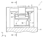
図1ないし図3に示すように、本発明の第1の実施の形態に係る塗布装置1は、塗布対象物である基板Kが水平状態(図1中、X軸方向とそれに直交するY軸方向に沿う状態)で載置されるステージ2と、そのステージ2上の基板Kに向けて塗布液を液滴として吐出する塗布ヘッド3と、その塗布ヘッド3をX軸方向に移動させるX軸移動機構4と、塗布ヘッド3をX軸移動機構4と共に支持する支持部材5と、塗布ヘッド3の吐出を安定させる吐出安定装置6と、ステージ2及び吐出安定装置6をY軸方向に個別に移動させるY軸移動機構7と、支持部材5及びY軸移動機構7を支持する架台8と、各部を制御する制御部9とを備えている。   As shown in FIGS. 1 to 3, the coating apparatus 1 according to the first embodiment of the present invention is such that the substrate K as a coating target is in a horizontal state (in FIG. 1, the X axis direction and the Y axis perpendicular thereto) Stage 2 placed in a state along the direction), a coating head 3 that discharges the coating liquid as droplets toward the substrate K on the stage 2, and an X-axis that moves the coating head 3 in the X-axis direction. The moving mechanism 4, the support member 5 that supports the coating head 3 together with the X-axis moving mechanism 4, the discharge stabilizing device 6 that stabilizes the discharge of the coating head 3, and the stage 2 and the discharge stabilizing device 6 are individually provided in the Y-axis direction. A Y-axis moving mechanism 7 to be moved, a support member 5 and a gantry 8 that supports the Y-axis moving mechanism 7, and a control unit 9 that controls each part are provided.

ステージ2は、ガラス基板などの基板Kが載置される移動テーブルであり、Y軸移動機構7を介して架台8の上面に設けられている。このステージ2には、基板Kが自重により載置されるが、これに限るものではなく、例えば、その基板Kを保持するため、静電チャックや吸着チャック等の機構を設けるようにしても良い。   The stage 2 is a moving table on which a substrate K such as a glass substrate is placed, and is provided on the upper surface of the gantry 8 via the Y-axis moving mechanism 7. The substrate K is placed on the stage 2 by its own weight. However, the present invention is not limited to this. For example, in order to hold the substrate K, a mechanism such as an electrostatic chuck or an adsorption chuck may be provided. .

塗布ヘッド3は、支持部材5にX軸移動機構4を介してステージ2上に配設されており、インクなどの塗布液を液滴として吐出する吐出ヘッドである。なお、塗布液は、その塗布液を収容する液体タンクからチューブなどの配管を介して供給される。この塗布液は、基板K上に残留物として残留する溶質と、その溶質を溶解(分散)させる溶媒とにより構成された溶液である。例えば、基板K上に配向膜やレジストなどの機能性薄膜を形成する場合には、塗布液としてポリイミド(PI)溶液が用いられる。   The coating head 3 is a discharge head that is disposed on the stage 2 via the X-axis moving mechanism 4 on the support member 5 and discharges a coating liquid such as ink as droplets. In addition, a coating liquid is supplied through piping, such as a tube, from the liquid tank which accommodates the coating liquid. This coating solution is a solution composed of a solute that remains as a residue on the substrate K and a solvent that dissolves (disperses) the solute. For example, when a functional thin film such as an alignment film or a resist is formed on the substrate K, a polyimide (PI) solution is used as the coating solution.

この塗布ヘッド3は、液滴を吐出するための複数の吐出孔(オリフィス)3aを有し(図4参照)、それらの吐出孔3aにそれぞれ対応する複数の圧電素子を内蔵している。塗布ヘッド3は制御部9に電気的に接続されており、その駆動が制御部9により制御され、各圧電素子に対する駆動電圧の印加に応じて各吐出孔3aから液滴を吐出する。各吐出孔3aは、所定のピッチ(間隔)で直線状に一列や二列に並べられ(図4では、二列)、塗布ヘッド3の吐出面(オリフィス面)M1に形成されている。例えば、吐出孔3aの数は数十個から数百個程度であり、吐出孔3aの直径は数μmから数十μm程度であり、さらに、吐出孔3aのピッチは数十μmから数百μm程度である。   The coating head 3 has a plurality of ejection holes (orifices) 3a for ejecting droplets (see FIG. 4), and incorporates a plurality of piezoelectric elements respectively corresponding to the ejection holes 3a. The coating head 3 is electrically connected to the control unit 9, and its driving is controlled by the control unit 9, and droplets are ejected from each ejection hole 3 a in response to application of a driving voltage to each piezoelectric element. Each discharge hole 3a is arranged in a line or two lines in a straight line at a predetermined pitch (interval) (two lines in FIG. 4), and is formed on the discharge surface (orifice surface) M1 of the coating head 3. For example, the number of discharge holes 3a is about several tens to several hundreds, the diameter of the discharge holes 3a is about several μm to several tens of μm, and the pitch of the discharge holes 3a is several tens μm to several hundreds of μm. Degree.

X軸移動機構4は、支持部材5に設けられており、塗布ヘッド3をステージ2上の基板Kの塗布面に沿うX軸方向に移動させる移動機構である。このX軸移動機構4は制御部9に電気的に接続されており、その駆動が制御部9により制御される。X軸移動機構4としては、例えば、サーボモータを駆動源とする送りねじ機構やリニアモータを駆動源とする移動機構などが用いられる。   The X-axis movement mechanism 4 is provided on the support member 5 and is a movement mechanism that moves the coating head 3 in the X-axis direction along the coating surface of the substrate K on the stage 2. The X-axis moving mechanism 4 is electrically connected to the control unit 9 and its driving is controlled by the control unit 9. As the X-axis moving mechanism 4, for example, a feed screw mechanism using a servo motor as a driving source, a moving mechanism using a linear motor as a driving source, or the like is used.

支持部材5は、X軸方向に長尺な門型の形状に形成されており、ステージ2及びY軸移動機構7を跨ぐように架台8の上面に設けられている。この支持部材5の梁部はX軸方向に平行にステージ2の載置面に対して水平にされ、支持部材5の脚部は架台8に固定されている。   The support member 5 is formed in a gate shape that is long in the X-axis direction, and is provided on the upper surface of the gantry 8 so as to straddle the stage 2 and the Y-axis moving mechanism 7. The beam portion of the support member 5 is parallel to the X-axis direction and is horizontal to the mounting surface of the stage 2, and the leg portion of the support member 5 is fixed to the gantry 8.

吐出安定装置6は、吐出安定槽6aと、その吐出安定槽6aをZ軸方向に移動させる槽移動機構6bとを備えている。この吐出安定装置6はY軸移動機構7を介して架台8の上面に設けられており、Y軸方向に移動可能に形成されている。   The discharge stabilizing device 6 includes a discharge stabilizing tank 6a and a tank moving mechanism 6b that moves the discharge stabilizing tank 6a in the Z-axis direction. The discharge stabilizing device 6 is provided on the upper surface of the gantry 8 via the Y-axis moving mechanism 7 and is formed to be movable in the Y-axis direction.

吐出安定槽6aは、図3に示すように、塗布ヘッド3のダミー吐出動作(フラッシング動作)により吐出された液滴を受け取る受け皿として機能する第1容器H1と、塗布液に対する吸液性を有する吸収体11を収容する第2容器H2とを有している。この吐出安定槽6aは、塗布ヘッド3の移動方向であるX軸方向に長く(図2参照)、上方が開口する箱形状に形成されており、その吐出安定槽6aがX軸方向に伸びる仕切板により仕切られることにより、第1容器H1及び第2容器H2が形成されている。   As shown in FIG. 3, the discharge stabilization tank 6 a has a first container H <b> 1 that functions as a receiving tray that receives droplets discharged by a dummy discharge operation (flushing operation) of the application head 3, and has a liquid absorption property for the application liquid. It has the 2nd container H2 which accommodates the absorber 11. FIG. The discharge stabilization tank 6a is long in the X-axis direction, which is the moving direction of the coating head 3 (see FIG. 2), and is formed in a box shape that opens upward, and the discharge stabilization tank 6a extends in the X-axis direction. The first container H1 and the second container H2 are formed by being partitioned by the plate.

第2容器H2には、吸収体11を保持する保持部材12がX軸方向に沿わされて回転軸13により回転可能に設けられている。保持部材12は角柱状に形成されており、この保持部材12には回転軸13が固定されている。回転軸13には、駆動源となるモータなどの回転駆動部が接続されている。この回転駆動部は制御部9に電気的に接続されており、その駆動が制御部9により制御される。   In the second container H2, a holding member 12 that holds the absorber 11 is provided along the X-axis direction so as to be rotatable by the rotary shaft 13. The holding member 12 is formed in a prismatic shape, and a rotating shaft 13 is fixed to the holding member 12. The rotary shaft 13 is connected to a rotary drive unit such as a motor serving as a drive source. The rotation drive unit is electrically connected to the control unit 9, and the drive is controlled by the control unit 9.

槽移動機構6bは、Y軸方向に移動可能にY軸移動機構7上に設けられている。この槽移動機構6bは、吐出安定槽6aをZ軸方向に移動可能に支持し、塗布ヘッド3に対して吐出安定槽6aをZ軸方向に接離させるZ軸移動機構であり、言い換えると、塗布ヘッド3の吐出面M1に対して吐出安定槽6a内の吸収体11をZ軸方向に接離させる吸収体移動機構である。この槽移動機構6bは制御部9に電気的に接続されており、その駆動が制御部9により制御される。槽移動機構6bとしては、例えば、シリンダやサーボモータを駆動源とする送りねじ機構などが用いられる。   The tank moving mechanism 6b is provided on the Y-axis moving mechanism 7 so as to be movable in the Y-axis direction. The tank moving mechanism 6b is a Z-axis moving mechanism that supports the discharge stabilizing tank 6a so as to be movable in the Z-axis direction and moves the discharge stabilizing tank 6a in and out of the coating head 3 in the Z-axis direction. This is an absorber moving mechanism that makes the absorber 11 in the discharge stabilizing tank 6a contact and separate in the Z-axis direction with respect to the discharge surface M1 of the coating head 3. The tank moving mechanism 6 b is electrically connected to the control unit 9, and its driving is controlled by the control unit 9. As the tank moving mechanism 6b, for example, a feed screw mechanism using a cylinder or a servo motor as a drive source is used.

Y軸移動機構7は、ステージ2及び吐出安定装置6をY軸方向に案内して個別に移動させる移動機構であり、架台8の上面に固定されて設けられている。このY軸移動機構7は制御部9に電気的に接続されており、その駆動が制御部9により制御される。Y軸移動機構7としては、例えば、サーボモータを駆動源とする送りねじ機構やリニアモータを駆動源とする移動機構などが用いられる。   The Y-axis moving mechanism 7 is a moving mechanism that guides the stage 2 and the discharge stabilizing device 6 in the Y-axis direction and moves them individually, and is fixed to the upper surface of the gantry 8. The Y-axis moving mechanism 7 is electrically connected to the control unit 9 and its driving is controlled by the control unit 9. As the Y-axis moving mechanism 7, for example, a feed screw mechanism using a servo motor as a driving source, a moving mechanism using a linear motor as a driving source, or the like is used.

架台8は、床面上に設置され、支持部材5やY軸移動機構7などを床面から所定の高さ位置に支持する支持台である。架台8の上面は平面に形成されており、この架台8の上面に支持部材5やY軸移動機構7などが載置されている。また、架台8の内部には、制御部9が設けられている。   The gantry 8 is a support base that is installed on the floor surface and supports the support member 5, the Y-axis movement mechanism 7, and the like at a predetermined height position from the floor surface. The upper surface of the gantry 8 is formed into a flat surface, and the support member 5 and the Y-axis moving mechanism 7 are placed on the upper surface of the gantry 8. A control unit 9 is provided inside the gantry 8.

制御部9は、各部を集中的に制御するマイクロコンピュータと、塗布に関する塗布情報や各種のプログラムなどを記憶する記憶部と、操作者からの操作を受け付ける操作部とを備えている。塗布情報は、ドットパターンなどの所定の塗布パターン、塗布ヘッド3の吐出周波数及び基板Kの移動速度に関する情報などを含んでいる。この塗布情報は、操作部に対する入力操作やデータ通信、あるいは携帯可能な記憶装置の媒介により記憶部に予め記憶されている。なお、記憶部としては、メモリやハードディスクドライブ(HDD)などが用いられる。   The control unit 9 includes a microcomputer that centrally controls each unit, a storage unit that stores application information and various programs related to application, and an operation unit that receives operations from an operator. The application information includes a predetermined application pattern such as a dot pattern, information on the ejection frequency of the application head 3 and the moving speed of the substrate K, and the like. This application information is stored in advance in the storage unit through an input operation to the operation unit, data communication, or mediation of a portable storage device. Note that a memory, a hard disk drive (HDD), or the like is used as the storage unit.

この制御部9は、塗布動作を行う場合、塗布情報に基づいて塗布ヘッド3及びY軸移動機構7を制御し、また、吐出安定動作を行う場合、吐出安定装置6及びY軸移動機構7を制御する。ここで、塗布動作は基板Kに液滴を塗布する動作であり、吐出安定動作はダミー吐出動作(フラッシング動作)やワイピング動作(拭き動作)などである。   The controller 9 controls the coating head 3 and the Y-axis moving mechanism 7 based on the coating information when performing the coating operation, and controls the ejection stabilizing device 6 and the Y-axis moving mechanism 7 when performing the stable discharging operation. Control. Here, the application operation is an operation for applying droplets to the substrate K, and the ejection stabilization operation is a dummy ejection operation (flushing operation), a wiping operation (wiping operation), or the like.

次いで、前述の吸収体11について詳しく説明する。   Next, the aforementioned absorber 11 will be described in detail.

図4に示すように、吸収体11の接触面M2は、塗布ヘッド3の吐出面M1とほぼ同じ大きさに形成されている。接触面M2のX軸方向の幅と吐出面M1のX軸方向の幅はほぼ同じ長さL1であり、接触面M2のY軸方向の幅と吐出面M1のY軸方向の幅はほぼ同じ長さL2である。なお、接触面M2とは、吸収体11が槽移動機構6bにより上昇した場合に、塗布ヘッド3の吐出面M1に接触する面(吸収体11の表面)である。   As shown in FIG. 4, the contact surface M <b> 2 of the absorber 11 is formed to have substantially the same size as the ejection surface M <b> 1 of the coating head 3. The width of the contact surface M2 in the X-axis direction and the width of the discharge surface M1 in the X-axis direction are substantially the same length L1, and the width of the contact surface M2 in the Y-axis direction and the width of the discharge surface M1 in the Y-axis direction are substantially the same. The length is L2. The contact surface M2 is a surface that contacts the ejection surface M1 of the coating head 3 (the surface of the absorber 11) when the absorber 11 is raised by the tank moving mechanism 6b.

ここで、通常、塗布ヘッド3の構造上、吐出孔3aがX軸方向あるいはY軸方向に並ぶ幅、すなわちX軸方向の吐出幅は吐出面M1のX軸方向の幅L1より小さい長さL1aとなり、Y軸方向の吐出幅は吐出面M1のY軸方向の幅L2より小さい長さL2aとなる。このため、塗布ヘッド3のX軸方向及びY幅方向における両端には、吐出孔3aがない領域が存在することになり、特に、その領域はY軸方向の両端に比べX軸方向の両端で大きくなる。   Here, normally, due to the structure of the coating head 3, the width in which the discharge holes 3a are arranged in the X-axis direction or the Y-axis direction, that is, the discharge width in the X-axis direction is a length L1a that is smaller than the width L1 in the X-axis direction of the discharge surface M1. Thus, the discharge width in the Y-axis direction is a length L2a that is smaller than the width L2 in the Y-axis direction of the discharge surface M1. For this reason, there are regions where the ejection holes 3a are not present at both ends in the X-axis direction and the Y-width direction of the coating head 3, and in particular, these regions are at both ends in the X-axis direction compared to both ends in the Y-axis direction. growing.

この吸収体11は、塗布液により濡れた状態で、槽移動機構6bによりZ軸方向に移動して塗布ヘッド3の吐出面M1に接触し、その吐出面M1に接触しながらY軸移動機構7によりY軸方向に移動することにより、塗布ヘッド3の吐出面M1を適度に濡らす。このとき、吸収体11の接触面M2は、全面にわたって塗布液を吸収している状態である。吸収体11としては、用いる塗布液に対する吸液性が考慮され、例えば、繊維部材や多孔質部材などが用いられる。   The absorbent body 11 is wetted by the coating liquid and is moved in the Z-axis direction by the tank moving mechanism 6b to come into contact with the ejection surface M1 of the coating head 3, and the Y-axis movement mechanism 7 while contacting the ejection surface M1. By moving in the Y-axis direction, the discharge surface M1 of the coating head 3 is appropriately wetted. At this time, the contact surface M2 of the absorber 11 is in a state of absorbing the coating liquid over the entire surface. As the absorbent body 11, liquid absorbability with respect to the coating liquid to be used is considered, and for example, a fiber member or a porous member is used.

なお、塗布液は、塗布ヘッド3により吸収体11の接触面M2の全面に供給される。すなわち、塗布ヘッド3は吸収体11から所定距離だけ離間し、その状態で吸収体11の接触面M2に向けて各吐出孔3aから液滴を吐出し、吸収体11の接触面M2に着弾させる。その着弾した液滴である塗布液がその接触面M2から吸収体11により吸い込まれて蓄えられる。   The coating liquid is supplied to the entire contact surface M2 of the absorber 11 by the coating head 3. That is, the coating head 3 is separated from the absorber 11 by a predetermined distance, and in this state, droplets are ejected from the ejection holes 3a toward the contact surface M2 of the absorber 11 and land on the contact surface M2 of the absorber 11. . The coating liquid as the landed droplets is sucked and stored by the absorber 11 from the contact surface M2.

この吸収体11に対する塗布ヘッド3の吐出動作(濡らし動作)においては、吸収体11のX軸方向の幅L1と塗布ヘッド3のX軸方向の吐出幅L1aとの関係、さらに、吸収体11のY軸方向の幅L2と塗布ヘッド3のY軸方向の吐出幅L2aとの関係から、塗布ヘッド3と吸収体11とを相対移動すると良い。   In the discharge operation (wetting operation) of the coating head 3 with respect to the absorber 11, the relationship between the width L1 of the absorber 11 in the X-axis direction and the discharge width L1a of the coating head 3 in the X-axis direction, From the relationship between the width L2 in the Y-axis direction and the discharge width L2a in the Y-axis direction of the coating head 3, the coating head 3 and the absorber 11 may be relatively moved.

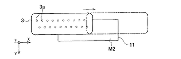
例えば、図5に示すように、塗布ヘッド3は、その吐出面M1が四分の一程度吸収体11の接触面M2に対向した状態(吐出孔3aの半分程度が吸収体11に対向した状態、すなわち、上列の吐出孔3aが接触面M2の上端部に対向し吐出孔3aの列の右端部が接触面の中央部に位置する状態)から、X軸移動機構4によりX軸方向の図中矢印の右方向に移動しつつ、各吐出孔3aから液滴を順次吐出し、図中の二点鎖線の位置(吐出孔3aの列の左端部が接触面の中央部に達する位置)まで移動する。   For example, as shown in FIG. 5, the coating head 3 has a state in which the discharge surface M1 faces the contact surface M2 of the absorber 11 by about a quarter (a state in which about half of the discharge holes 3a face the absorber 11). That is, from the state in which the upper row of discharge holes 3a faces the upper end of the contact surface M2 and the right end of the row of discharge holes 3a is located at the center of the contact surface, the X axis moving mechanism 4 While moving in the right direction of the arrow in the figure, the droplets are sequentially ejected from each ejection hole 3a, and the position of the two-dot chain line in the figure (position where the left end of the row of ejection holes 3a reaches the center of the contact surface) Move up.

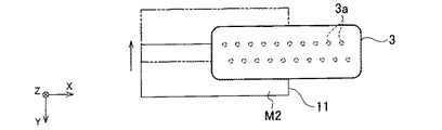
次に、図6に示すように、吸収体11は、その接触面M2が四分の一程度塗布ヘッド3の吐出面M1に対向した状態で(吐出孔3aの半分程度が吸収体11に対向した状態すなわち、上列の吐出孔3aが接触面M2の上端部に対向し吐出孔3aの列の左端部が接触面の中央部に位置する状態)から、Y軸移動機構7による吐出安定装置6の移動によりY軸方向の図中矢印の上方向に移動し、図中の二点鎖線の位置(下列の吐出孔3aが接触面の下端部に対向する位置)まで移動する。このとき、塗布ヘッド3は、各吐出孔3aから液滴を順次吐出する。 Next, as shown in FIG. 6, the absorber 11 has the contact surface M <b> 2 opposed to the ejection surface M <b> 1 of the coating head 3 (about half of the ejection holes 3 a faces the absorber 11). ( I.e., a state where the upper row of discharge holes 3a faces the upper end of the contact surface M2 and the left end of the row of discharge holes 3a is located at the center of the contact surface), As the device 6 moves, it moves upward in the direction of the arrow in the Y-axis direction and moves to the position of the two-dot chain line in the drawing (the position where the lower row of the discharge holes 3a faces the lower end of the contact surface). At this time, the coating head 3 sequentially discharges droplets from the respective discharge holes 3a.

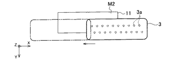
次いで、図7に示すように、塗布ヘッド3は、その吐出面M1が四分の一程度吸収体11の接触面M2に対向した状態で(吐出孔3aの半分程度が吸収体11に対向した状態、すなわち、下列の吐出孔3aが接触面M2の下端部に対向し吐出孔3aの列の左端部が接触面の中央部に位置する状態)から、X軸移動機構4によりX軸方向の図中矢印の左方向に移動しつつ、各吐出孔3aから液滴を順次吐出し、図中の二点鎖線の位置(吐出孔3aの列の右端部が接触面の中央部に達する位置)まで移動する。   Next, as shown in FIG. 7, the coating head 3 has the ejection surface M <b> 1 opposed to the contact surface M <b> 2 of the absorber 11 by about a quarter (about half of the ejection holes 3 a opposed to the absorber 11. State, that is, a state in which the lower row of the discharge holes 3a is opposed to the lower end of the contact surface M2 and the left end of the row of the discharge holes 3a is located at the center of the contact surface) While moving to the left of the arrow in the figure, droplets are sequentially ejected from each ejection hole 3a, and the position of the two-dot chain line in the figure (position where the right end of the row of ejection holes 3a reaches the center of the contact surface) Move up.

最後に、図8に示すように、吸収体11は、その接触面M2が四分の一程度塗布ヘッド3の吐出面M1に対向した状態で(吐出孔3aの半分程度が吸収体11に対向した状態、すなわち、下列の吐出孔3aが接触面M2の下端部に対向し吐出孔3aの列の右端部が接触面の中央部に位置する状態)から、Y軸移動機構7による吐出安定装置6の移動によりY軸方向の図中矢印の下方向に移動し、図中の二点鎖線の位置(上列の吐出孔3aが接触面の上端部に対向する位置)まで移動する。このとき、塗布ヘッド3は、各吐出孔3aから液滴を順次吐出する。   Finally, as shown in FIG. 8, the absorber 11 has the contact surface M <b> 2 opposed to the ejection surface M <b> 1 of the coating head 3 (about half of the ejection holes 3 a faces the absorber 11). A state where the discharge holes 3a in the lower row face the lower end portion of the contact surface M2 and the right end portion of the row of the discharge holes 3a is located at the center portion of the contact surface)). 6 moves downward in the direction of the arrow in the Y-axis direction to the position of the two-dot chain line in the drawing (the position where the upper row of discharge holes 3a faces the upper end of the contact surface). At this time, the coating head 3 sequentially discharges droplets from the respective discharge holes 3a.

上述の図5ないし図8の動作における塗布ヘッド3と吸収体11との相対移動中、塗布ヘッド3の各吐出孔3aからは、吸収体11の接触面M2に所望の濡れ状態を得るために予め設定された1滴当たりの吐出量と単位時間当たりの吐出回数で、液滴が吐出される。なお、塗布ヘッド3と吸収体11との相対移動方向を切り換えるとき、両者の相対移動が一時的に停止するので、この停止期間中は各吐出孔3aからの塗布液の吐出を停止させても良いし、相対移動中よりも少ない吐出量や吐出回数としても良い。   In order to obtain a desired wet state on the contact surface M2 of the absorber 11 from each discharge hole 3a of the coating head 3 during the relative movement between the coating head 3 and the absorber 11 in the operation of FIGS. Droplets are ejected at a preset ejection amount per droplet and the number of ejections per unit time. Note that when the relative movement direction of the coating head 3 and the absorber 11 is switched, the relative movement of both of them temporarily stops. Therefore, even if the discharge of the coating liquid from each discharge hole 3a is stopped during this stop period. It is good, and it is good also as discharge amount and discharge frequency smaller than during relative movement.

このようにして、塗布ヘッド3及び吸収体11は相対移動しつつ、塗布ヘッド3は各吐出孔3aから液滴を順次吐出し続けることによって、塗布液が吸収体11の接触面M2の全面に供給される。これにより、吸収体11の接触面M2は均一に塗布液により濡れた状態となる。その後、均一な濡れ状態の吸収体11により塗布ヘッド3の吐出面M1がワイピングされる。   In this way, the coating head 3 and the absorber 11 move relative to each other, and the coating head 3 continuously discharges droplets from the respective discharge holes 3a, so that the coating liquid is applied to the entire contact surface M2 of the absorber 11. Supplied. Thereby, the contact surface M2 of the absorber 11 is uniformly wetted by the coating liquid. Thereafter, the ejection surface M1 of the coating head 3 is wiped by the absorbent body 11 in a uniform wet state.

次に、前述の塗布装置1が行う塗布動作(吐出安定動作を含む)について説明する。なお、塗布装置1の制御部9が各種のプログラムに基づいて塗布処理(吐出安定処理を含む)を実行する。   Next, a coating operation (including a discharge stable operation) performed by the above-described coating apparatus 1 will be described. In addition, the control part 9 of the coating device 1 performs a coating process (including a discharge stabilization process) based on various programs.

図9に示すように、まず、プリウエット処理(ステップS0)が実行され、上述の動作によって吸収体11が均一な濡れ状態とされる。次いで、基板Kがステージ2上に搬入されたか否かが判断され(ステップS1)、基板Kがステージ2上に搬入されていないと判断した場合には(ステップS1のNO)、所定のダミー運転吐出時間が経過したか否かが判断され(ステップS2)、所定のダミー運転吐出時間が経過していないと判断された場合には(ステップS2のNO)、処理がステップS1に戻される。   As shown in FIG. 9, first, a prewetting process (step S0) is performed, and the absorber 11 is brought into a uniform wet state by the above-described operation. Next, it is determined whether or not the substrate K has been loaded onto the stage 2 (step S1). If it is determined that the substrate K has not been loaded onto the stage 2 (NO in step S1), a predetermined dummy operation is performed. It is determined whether or not the discharge time has elapsed (step S2). If it is determined that the predetermined dummy operation discharge time has not elapsed (NO in step S2), the process returns to step S1.

所定のダミー運転吐出時間が経過したと判断された場合には(ステップS2のYES)、追加プリウエット時間が経過したか否かが判断される(ステップS3)。追加プリウエット時間が経過したと判断された場合には(ステップS3のYES)、吸収体11を濡らす追加プリウエットが行われ(ステップS4)、追加プリウエット時間が経過していないと判断された場合には(ステップS3のNO)、ダミー吐出が行われる(ステップS5)。その後、塗布ヘッド3の吐出面M1を濡らすワイピングが行われ(ステップS6)、処理がステップS1に戻される。なお、ダミー運転吐出時間及び追加プリウエット時間は予め記憶部に記憶されており、例えば、ダミー運転吐出時間は1分程度であり、追加プリウエット時間は10分程度である。   If it is determined that the predetermined dummy operation discharge time has elapsed (YES in step S2), it is determined whether or not an additional prewetting time has elapsed (step S3). When it is determined that the additional prewetting time has elapsed (YES in step S3), an additional prewetting for wetting the absorber 11 is performed (step S4), and it is determined that the additional prewetting time has not elapsed. In this case (NO in step S3), dummy ejection is performed (step S5). Thereafter, wiping to wet the ejection surface M1 of the coating head 3 is performed (step S6), and the process returns to step S1. The dummy operation discharge time and the additional prewetting time are stored in advance in the storage unit. For example, the dummy operation discharge time is about 1 minute and the additional prewetting time is about 10 minutes.

ここで、追加プリウエットを行う場合には、まず、吐出安定装置6がY軸移動機構7により第2容器H2内の吸収体11が塗布ヘッド3に対向するプリウエット位置まで移動し、その後、プリウエット位置に存在する吸収体11に向けて塗布ヘッド3が各吐出孔3aから液滴を吐出する。このとき、前述で説明したように(図5ないし図8参照)、塗布ヘッド3及び吸収体11は相対移動し、塗布ヘッド3は各吐出孔3aから液滴を順次吐出し続け、塗布液を吸収体11の接触面M2の全面に供給する。これにより、吸収体11の接触面M2は均一に塗布液により濡れた状態となる。なお、ステージ2はY軸移動機構7により追加プリウエットを妨げない退避位置まで移動して待機している。   Here, when performing additional prewetting, first, the discharge stabilizing device 6 is moved to the prewetting position where the absorber 11 in the second container H2 faces the coating head 3 by the Y-axis moving mechanism 7, and then, The coating head 3 ejects droplets from the respective ejection holes 3a toward the absorber 11 existing at the pre-wet position. At this time, as described above (see FIGS. 5 to 8), the coating head 3 and the absorber 11 move relative to each other, and the coating head 3 sequentially discharges the droplets sequentially from the respective discharge holes 3a to apply the coating liquid. It supplies to the whole contact surface M2 of the absorber 11. FIG. Thereby, the contact surface M2 of the absorber 11 is uniformly wetted by the coating liquid. The stage 2 is moved to a retreat position that does not interfere with the additional pre-wet by the Y-axis moving mechanism 7 and is on standby.

この追加プリウエット時における、各吐出孔3aから吐出させる液滴の1滴当たりの吐出量と単位時間当たりの吐出回数は、ステップS0におけるプリウエットと同じでも良いが、吸収体11が濡れた状態であることを考慮して、ステップS0におけるプリウエットよりも1滴あたりの吐出量や単位時間当たりの吐出回数を少なく設定しても良い。   In this additional pre-wetting, the discharge amount per droplet of the droplets discharged from each discharge hole 3a and the number of discharges per unit time may be the same as those in step S0, but the absorber 11 is wet. In view of this, the discharge amount per droplet and the number of discharges per unit time may be set smaller than the pre-wet in step S0.

一方、ダミー吐出を行う場合には、まず、吐出安定装置6がY軸移動機構7により第1容器H1が塗布ヘッド3に対向するダミー吐出位置まで移動し、その後、ダミー吐出位置に存在する第1容器H1に向けて塗布ヘッド3が各吐出孔3aから液滴を吐出する。これにより、吐出孔3a内で変質した塗布液や吐出孔3aに付着した付着物(凝固物や異物など)が取り除かれるので、吐出異常の発生が防止される。なお、ステージ2はY軸移動機構7によりダミー吐出を妨げない退避位置まで移動して待機している。   On the other hand, when performing the dummy discharge, first, the discharge stabilizing device 6 is moved to the dummy discharge position where the first container H1 faces the coating head 3 by the Y-axis moving mechanism 7, and then the first position existing at the dummy discharge position. The coating head 3 ejects droplets from the respective ejection holes 3a toward one container H1. As a result, the coating liquid that has deteriorated in the discharge hole 3a and the deposits (solidified matter, foreign matter, etc.) adhering to the discharge hole 3a are removed, thereby preventing the occurrence of abnormal discharge. Note that the stage 2 is moved to a retracted position by the Y-axis moving mechanism 7 so as not to disturb the dummy discharge and is on standby.

また、ワイピングを行う場合には、まず、吐出安定装置6がY軸移動機構7により第2容器H2内の吸収体11が塗布ヘッド3に対向するワイピング位置まで移動し、その後、槽移動機構6bにより第2容器H2内の吸収体11が塗布ヘッド3の吐出面M1に接触する接触位置までZ軸方向に移動し、吸収体11の接触面M2が塗布ヘッド3の吐出面M1に接触する。このとき、吸収体11は前述のプリウエットや追加プリウエットによりその接触面M2の全面が良好に濡れた状態になっている。その後、吐出安定装置6は、吸収体11の接触面M2を塗布ヘッド3の吐出面M1に接触させつつ、Y軸移動機構7によりY軸方向に移動し、吸収体11により塗布ヘッド3の吐出面M1の全面を払拭すると共に均一に濡らす。   When wiping is performed, first, the discharge stabilizing device 6 is moved to the wiping position where the absorber 11 in the second container H2 faces the coating head 3 by the Y-axis moving mechanism 7, and then the tank moving mechanism 6b. As a result, the absorber 11 in the second container H2 moves in the Z-axis direction to a contact position where the absorber 11 contacts the ejection surface M1 of the coating head 3, and the contact surface M2 of the absorber 11 contacts the ejection surface M1 of the coating head 3. At this time, the entire surface of the contact surface M2 of the absorber 11 is satisfactorily wetted by the above-described prewetting or additional prewetting. Thereafter, the discharge stabilizing device 6 moves in the Y-axis direction by the Y-axis moving mechanism 7 while bringing the contact surface M2 of the absorber 11 into contact with the discharge surface M1 of the coating head 3, and discharges the coating head 3 by the absorber 11. Wipe the entire surface M1 and wet it uniformly.

前述のステップS1において、基板Kがステージ2上に搬入されたと判断した場合には(ステップS1のYES)、塗布ヘッド3の吐出面M1を濡らす前述と同様のワイピングが行われ(ステップS7)、吐出異常の発生などを確認する吐出確認(吐出検査)があるか否か(吐出確認を行う否か)が判断される(ステップS8)。吐出確認があると判断された場合には(ステップS8のYES)、吐出確認が行われ(ステップS9)、吐出確認がないと判断された場合には(ステップS8のNO)、例えば1分程度のダミー吐出が行われる(ステップS10)。なお、吐出確認の有り無しは操作部に対する操作者の入力操作により予め設定されている。   If it is determined in step S1 that the substrate K has been loaded onto the stage 2 (YES in step S1), wiping similar to that described above is performed to wet the ejection surface M1 of the coating head 3 (step S7). It is determined whether or not there is a discharge confirmation (discharge inspection) for confirming the occurrence of a discharge abnormality or not (whether or not the discharge confirmation is performed) (step S8). When it is determined that there is discharge confirmation (YES in step S8), discharge confirmation is performed (step S9). When it is determined that there is no discharge confirmation (NO in step S8), for example, about 1 minute. Dummy discharge is performed (step S10). The presence / absence of discharge confirmation is set in advance by an operator's input operation to the operation unit.

その後、塗布が行われる(ステップS11)。所定の基板枚数分の塗布が完了したか否かが判断され(ステップS12)、所定の基板枚数分の塗布が完了していないと判断された場合には(ステップS12のNO)、処理がステップS1に戻され、所定の基板枚数分の塗布が完了したと判断された場合には(ステップS12のYES)、処理が終了する。   Then, application | coating is performed (step S11). It is determined whether or not the application for the predetermined number of substrates has been completed (step S12), and if it is determined that the application for the predetermined number of substrates has not been completed (NO in step S12), the process proceeds to step S12. Returning to S1, if it is determined that the application for the predetermined number of substrates has been completed (YES in step S12), the process ends.

ここで、塗布を行う場合、制御部9は、塗布情報に基づいてX軸移動機構4及びY軸移動機構7を制御し、塗布ヘッド3を基板Kの塗布面に対向する塗布開始位置に移動させる。なお、吐出安定装置6はY軸移動機構7により塗布を妨げない退避位置まで移動して待機している。その後、制御部9は、塗布情報に基づいて、X軸移動機構4及びY軸移動機構7に加え、塗布ヘッド3を制御し、ステージ2上の基板Kと塗布ヘッド3とを相対移動させ、塗布ヘッド3の各吐出孔3aから液滴を吐出させてステージ2上の基板Kに塗布液を塗布する。   Here, when performing coating, the control unit 9 controls the X-axis moving mechanism 4 and the Y-axis moving mechanism 7 based on the coating information, and moves the coating head 3 to the coating start position facing the coating surface of the substrate K. Let In addition, the discharge stabilizing device 6 is moved to a retreat position where the application is not hindered by the Y-axis moving mechanism 7 and is on standby. Thereafter, the control unit 9 controls the coating head 3 in addition to the X-axis moving mechanism 4 and the Y-axis moving mechanism 7 based on the coating information, and relatively moves the substrate K on the stage 2 and the coating head 3, A droplet is ejected from each ejection hole 3 a of the coating head 3 to apply the coating liquid to the substrate K on the stage 2.

以上説明したように、本発明の第1の実施の形態によれば、吸液性を有する吸収体11の接触面M2の全面を濡らし、この吸収体11で塗布ヘッド3の吐出面M1をワイピングするので、吐出面11に付着した余分な塗布液を除去することができ、しかも、濡れた接触面M2を塗布ヘッド3の吐出面M1に接触させて塗布ヘッド3の吐出面M1の全面を濡らすことによって、その塗布ヘッド3の吐出面M1の全面を容易に均一な濡れ状態にすることが可能になる。これにより、塗布ヘッド3の吐出面M1では、余分な塗布液が除去されるとともに、その全域には溶媒雰囲気が形成されることから、塗布ヘッド3の吐出孔3a付近に付着した塗布液が乾燥して凝固物となることや、塗布ヘッド3の吐出面M1において吐出孔3aから離れた位置に付着した塗布液などが乾燥して凝固物となることなどが防止されるので、吐出面M1に付着した塗布液の乾燥に起因して吐出曲がりなどの吐出異常が発生することを抑止することができる。   As described above, according to the first embodiment of the present invention, the entire contact surface M2 of the absorbent body 11 having liquid absorbency is wetted, and the ejection surface M1 of the coating head 3 is wiped with this absorbent body 11. Therefore, it is possible to remove excess coating liquid adhering to the ejection surface 11 and to wet the entire ejection surface M1 of the coating head 3 by bringing the wet contact surface M2 into contact with the ejection surface M1 of the coating head 3. As a result, the entire ejection surface M1 of the coating head 3 can be easily brought into a uniform wet state. As a result, excess coating liquid is removed from the ejection surface M1 of the coating head 3 and a solvent atmosphere is formed in the entire area, so that the coating liquid adhering to the vicinity of the ejection holes 3a of the coating head 3 is dried. Thus, it is prevented that the solidified product is formed, and the coating liquid or the like adhering to a position away from the discharge hole 3a on the discharge surface M1 of the coating head 3 is dried to be a solidified product. It is possible to suppress occurrence of discharge abnormality such as discharge bending due to drying of the applied coating liquid.

特に、塗布ヘッド3及び吸収体11を相対移動させながら、塗布ヘッド3の各吐出孔3aから液滴を順次吐出し続け、吸収体11の接触面M2の全面に塗布液を供給することによって、吸収体11の接触面M2を均一に塗布液により濡れた状態とすることが可能になるので、その吸収体11を用いて塗布ヘッド3の吐出面M1の全面を均一に確実に濡らすことができる。   In particular, while moving the coating head 3 and the absorber 11 relative to each other, the liquid droplets are successively discharged from the discharge holes 3a of the coating head 3 and the coating liquid is supplied to the entire contact surface M2 of the absorber 11, Since the contact surface M2 of the absorber 11 can be uniformly wetted by the coating liquid, the entire surface of the ejection surface M1 of the coating head 3 can be uniformly and reliably wetted using the absorber 11. .

(第2の実施の形態)
本発明の第2の実施の形態について図10を参照して説明する。
(Second Embodiment)
A second embodiment of the present invention will be described with reference to FIG.

本発明の第2の実施の形態は第1の実施の形態と基本的に同じである。したがって、第2の実施の形態では、第1の実施の形態と異なる部分について説明し、第2の実施の形態で説明した部分と同じ部分の説明を省略する。   The second embodiment of the present invention is basically the same as the first embodiment. Therefore, in the second embodiment, parts different from the first embodiment will be described, and description of the same parts as those described in the second embodiment will be omitted.

図10に示すように、保持部材12は、吸収体11に供給する液体を流すための液体流路21を内蔵している。この液体流路21は、チューブやパイプなどの配管22を介して供給部23に接続されている。   As shown in FIG. 10, the holding member 12 has a built-in liquid channel 21 for flowing the liquid supplied to the absorber 11. The liquid flow path 21 is connected to a supply unit 23 via a pipe 22 such as a tube or a pipe.

液体流路21は保持部材12の内部で四本の流路に分岐している。四本の流路は、吸収体11の接触面M2を四分割し、各接触面M2に対応する四つの領域の中央に個別に接続されている。これにより、吸収体11の全体に均一に液体が供給されるので、その接触面M2の全面が均一に濡れることになる。また、配管22は、保持部材12の液体流路21と供給部23とを接続する接続経路として機能する。   The liquid channel 21 is branched into four channels inside the holding member 12. The four flow paths divide the contact surface M2 of the absorber 11 into four parts, and are individually connected to the centers of the four regions corresponding to the contact surfaces M2. Thereby, since the liquid is uniformly supplied to the entire absorber 11, the entire contact surface M2 is uniformly wetted. The pipe 22 functions as a connection path that connects the liquid flow path 21 of the holding member 12 and the supply unit 23.

なお、ここでは、液体流路21を保持部材12内で四本に分岐させているが、これに限るものではなく、例えば、六本に分岐させるようにしても良く、その数は制限されない。また、配管22を一本としているが、これに限るものではなく、例えば、四本設けるようにしても良い。この場合には、各接触面M2に対応する四つの領域に個別に連通する四本の液体流路を設け、それらの液体流路に四本の配管を接続する。   Here, the liquid flow path 21 is branched into four in the holding member 12, but is not limited to this. For example, the liquid flow path 21 may be branched into six, and the number is not limited. Moreover, although the piping 22 is made into one, it is not restricted to this, For example, you may make it provide four. In this case, four liquid flow paths individually communicating with four regions corresponding to the contact surfaces M2 are provided, and four pipes are connected to the liquid flow paths.

供給部23は、液体を貯留する貯留部やポンプ、流量調整弁などを備えている。貯留部は着脱可能に形成されており、その貯留部を変更することによって液体の種類を変更することが可能となる。この供給部23は制御部9に電気的に接続されており、その駆動が制御部9により制御され、吸収体11に配管22及び液体流路21を介して液体を供給する。液体としては、例えば、塗布ヘッド3が用いる塗布液と同じ液体として、PI(ポリイミド)液やNMP(N−メチル−2−ピロリドン)液などが用いられ、あるいは、その塗布液に応じた溶媒などが用いられる。   The supply unit 23 includes a storage unit that stores liquid, a pump, a flow rate adjustment valve, and the like. The storage part is formed so as to be detachable, and the type of liquid can be changed by changing the storage part. The supply unit 23 is electrically connected to the control unit 9, and the driving thereof is controlled by the control unit 9, and supplies the liquid to the absorber 11 through the pipe 22 and the liquid flow path 21. As the liquid, for example, a PI (polyimide) liquid, an NMP (N-methyl-2-pyrrolidone) liquid, or the like is used as the same liquid as the coating liquid used by the coating head 3, or a solvent according to the coating liquid. Is used.

制御部9は、吸収体11の接触面M2の全面が濡れるための所定時間だけ吸収体11に液体を供給するようにポンプや流量調整弁などを制御する。これ以外の制御としては、例えば、吸収体11の接触面M2の全面が濡れた状態を維持するようにポンプや流量調整弁などを制御したり、吸収体11の接触面M2の濡れ状態を検出する濡れ検出部を設け、検出した濡れ状態に応じて、吸収体11の接触面M2の全面が濡れた状態を維持するようにポンプや流量調整弁などを制御したりする。   The control unit 9 controls a pump, a flow rate adjusting valve, and the like so as to supply liquid to the absorber 11 for a predetermined time for the entire contact surface M2 of the absorber 11 to get wet. As other controls, for example, a pump, a flow rate adjusting valve, or the like is controlled so that the entire contact surface M2 of the absorber 11 is kept wet, or the wet state of the contact surface M2 of the absorber 11 is detected. A wetting detection unit is provided, and the pump, the flow rate adjusting valve, and the like are controlled so as to maintain the entire wetted contact surface M2 of the absorber 11 in accordance with the detected wet state.

ここで、濡れ検出部としては、例えば、反射型のレーザセンサなどが用いられる。すなわち、吸収体11の接触面は、濡れ具合(吸水量)に応じてレーザ光の反射率が変化する(吸水量が多いほど液体によるレーザ光の反射量が多くなるので反射率が高くなる)から、吸収体11の良好な濡れ状態におけるレーザセンサの出力値を予め測定して設定しておき、レーザセンサによる出力値が設定した出力値の許容値内となるようにプリウエットや追加プリウエットを実行するようにすれば良い。   Here, as the wetting detection unit, for example, a reflection type laser sensor or the like is used. That is, on the contact surface of the absorber 11, the reflectance of the laser light changes according to the wetness (amount of water absorption) (the greater the amount of water absorption, the greater the amount of reflection of the laser light by the liquid, so the reflectance increases). Thus, the output value of the laser sensor when the absorber 11 is in a good wet state is measured and set in advance, and the pre-wet and the additional pre-wet so that the output value by the laser sensor is within the allowable value of the set output value. Should be executed.

以上説明したように、本発明の第2の実施の形態によれば、第1の実施の形態と同様の効果を得ることができる。さらに、吸収体11に液体を供給する供給部23を吐出安定装置6に設け、その供給部23により吸収体11の接触面M2の全面に液体を供給することによって、吸収体11の接触面M2を均一に液体により濡れた状態とすることが可能になるので、その吸収体11を用いて塗布ヘッド3の吐出面M1の全面を均一に確実に濡らすことができる。   As described above, according to the second embodiment of the present invention, the same effect as in the first embodiment can be obtained. Further, a supply unit 23 for supplying liquid to the absorber 11 is provided in the discharge stabilizing device 6, and the liquid is supplied to the entire contact surface M 2 of the absorber 11 by the supply unit 23, whereby the contact surface M 2 of the absorber 11. Since the absorbent 11 can be used to uniformly wet the entire surface of the ejection surface M1 of the coating head 3.

なお、第2の実施の形態において、吸収体11の接触面M2を濡れた状態に維持する追加プレウエットの実行の要否を、レーザセンサを用いて判定するものとして説明したが、第1の実施の形態と同様に、経過時間に基づいて判定するようにしても良い。また、上述の第1の実施の形態において、追加プレウエットの実行の要否を、レーザセンサを用いて判定するようにしても良い。   In the second embodiment, the necessity of executing an additional prewet for maintaining the contact surface M2 of the absorber 11 in a wet state has been described as being determined using a laser sensor. Similar to the embodiment, the determination may be made based on the elapsed time. In the first embodiment described above, it may be determined using a laser sensor whether or not the additional pre-wetting is necessary.

(他の実施の形態)
なお、本発明は、前述の実施の形態に限るものではなく、その要旨を逸脱しない範囲において種々変更可能である。例えば、前述の実施の形態に示される全構成要素から幾つかの構成要素を削除しても良い。さらに、異なる実施の形態に亘る構成要素を適宜組み合わせても良い。また、前述の実施の形態においては、各種の数値を挙げているが、それらの数値は例示であり、限定されるものではない。
(Other embodiments)
The present invention is not limited to the above-described embodiment, and various modifications can be made without departing from the scope of the invention. For example, some components may be deleted from all the components shown in the above-described embodiment. Furthermore, you may combine the component covering different embodiment suitably. Moreover, in the above-mentioned embodiment, although various numerical values are mentioned, those numerical values are illustrations and are not limited.

前述の実施の形態においては、一つの塗布ヘッド3を設けているが、これに限るものではなく、例えば、基板Kの移動方向に直交するX軸方向に基板Kの幅全体を網羅するように複数の塗布ヘッド3を並べて設けるようにしても良く、あるいは、X軸方向に基板Kの幅全体より短く複数の塗布ヘッド3を並べて設けるようにしても良い。塗布ヘッド3を複数設けた場合には、塗布ヘッド3の台数分だけ吸収体11をX軸方向に並べて回転軸13に設けても良いし、あるいは、塗布ヘッド3と吸収体11とをX軸方向に相対移動させて一つの吸収体11を複数の塗布ヘッド3で共用するようにしても良い。   In the above-described embodiment, the single coating head 3 is provided. However, the present invention is not limited to this. For example, the entire width of the substrate K is covered in the X-axis direction orthogonal to the moving direction of the substrate K. A plurality of coating heads 3 may be provided side by side, or a plurality of coating heads 3 may be provided side by side shorter than the entire width of the substrate K in the X-axis direction. When a plurality of coating heads 3 are provided, absorbers 11 corresponding to the number of coating heads 3 may be arranged on the rotation shaft 13 in the X-axis direction, or the coating head 3 and the absorber 11 may be provided on the X-axis. One absorber 11 may be shared by a plurality of coating heads 3 by relative movement in the direction.

また、前述の実施の形態においては、ステージ2及び吐出安定装置6を個別にY軸方向に移動させる一つのY軸移動機構7を設けているが、これに限るものではなく、二つのY軸移動機構を設け、ステージ2及び吐出安定装置6を個別にY軸方向に移動させるようにしても良い。   In the above-described embodiment, one Y-axis moving mechanism 7 for individually moving the stage 2 and the discharge stabilizing device 6 in the Y-axis direction is provided. However, the present invention is not limited to this. A moving mechanism may be provided so that the stage 2 and the discharge stabilizing device 6 are individually moved in the Y-axis direction.

また、前述の実施の形態においては、保持部材12の一面に吸収体11を設けているが、これに限るものではなく、例えば、保持部材12における回転軸13の回転方向に並ぶ全面に吸収体11を設けるようにしても良く、あるいは、保持部材12を吸収材料により形成して吸収体11として用いるようにしても良い。これらの場合には、一面の吸収体11が汚れたり、破損したりした場合など、回転軸13を回転させることによって新たな吸収体11を用いることが可能となる。   In the above-described embodiment, the absorbent body 11 is provided on one surface of the holding member 12. However, the present invention is not limited to this. For example, the absorbent body is disposed on the entire surface of the holding member 12 aligned with the rotation direction of the rotation shaft 13. 11 may be provided, or the holding member 12 may be formed of an absorbent material and used as the absorbent body 11. In these cases, the new absorber 11 can be used by rotating the rotating shaft 13 such as when the absorber 11 on one surface is soiled or damaged.

1 塗布装置
2 ステージ
3 塗布ヘッド
3a 吐出孔
6 吐出安定装置
7 移動機構
11 吸収体
23 供給部
K 塗布対象物(基板)
M1 吐出面
M2 接触面
DESCRIPTION OF SYMBOLS 1 Application | coating apparatus 2 Stage 3 Application | coating head 3a Ejection hole 6 Ejection stabilization apparatus 7 Moving mechanism 11 Absorber 23 Supply part K Application | coating target object (board | substrate)
M1 discharge surface M2 contact surface

Claims (8)

塗布対象物が載置されるステージと、
液滴を吐出するための吐出孔が形成された吐出面を有し、前記ステージ上の前記塗布対象物に向けて前記吐出孔から塗布液を液滴として吐出する塗布ヘッドと、
前記ステージと前記塗布ヘッドとを前記ステージの面方向に相対移動させる移動機構と、
前記塗布ヘッドの前記吐出面に接触する接触面を有する吸液性の吸収体を有し、前記吸収体の前記接触面の全面を濡らし、濡れた前記接触面と前記塗布ヘッドの前記吐出面とを接触させて前記塗布ヘッドの前記吐出面の全面を濡らす吐出安定装置と、
を備えることを特徴とする塗布装置。
A stage on which the application object is placed;
An application head that has an ejection surface in which ejection holes for ejecting liquid droplets are formed, and ejects the coating liquid as droplets from the ejection holes toward the application object on the stage;
A moving mechanism for relatively moving the stage and the coating head in the surface direction of the stage;
A liquid-absorbing absorber having a contact surface in contact with the ejection surface of the coating head; wets the entire contact surface of the absorber; and the wet contact surface and the ejection surface of the coating head A discharge stabilizer for bringing the entire surface of the discharge surface of the coating head into contact with the discharge stabilizer,
A coating apparatus comprising:
前記吐出安定装置は、前記塗布ヘッドにより前記吸収体の前記接触面の全面に前記塗布液を供給することを特徴とする請求項1記載の塗布装置。   The coating apparatus according to claim 1, wherein the discharge stabilizing device supplies the coating liquid to the entire contact surface of the absorber by the coating head. 前記吐出安定装置は、前記吸収体に液体を供給する供給部を有し、前記供給部により前記吸収体の前記接触面の全面に前記液体を供給することを特徴とする請求項1記載の塗布装置。   The coating according to claim 1, wherein the discharge stabilizing device includes a supply unit that supplies a liquid to the absorber, and the liquid is supplied to the entire contact surface of the absorber by the supply unit. apparatus. 前記吐出安定装置は、前記塗布ヘッド及び前記吸収体を前記吐出面の面方向に相対移動させつつ、前記塗布ヘッドにより前記吸収体の前記接触面の全面に前記塗布液を供給することを特徴とする請求項2記載の塗布装置。   The ejection stabilization device supplies the coating liquid to the entire contact surface of the absorber by the coating head while relatively moving the coating head and the absorber in the surface direction of the ejection surface. The coating apparatus according to claim 2. 塗布対象物が載置されるステージと、液滴を吐出するための吐出孔が形成された吐出面を有し前記ステージ上の前記塗布対象物に向けて前記吐出孔から塗布液を液滴として吐出する塗布ヘッドと、前記ステージと前記塗布ヘッドとを前記ステージの面方向に相対移動させる移動機構とを用いて、前記ステージ上の前記塗布対象物に前記塗布液を塗布する塗布方法であって、
前記塗布ヘッドの前記吐出面に接触する接触面を有する吸液性の吸収体を用いて、前記吸収体の前記接触面の全面を濡らし、濡れた前記接触面と前記塗布ヘッドの前記吐出面とを接触させて前記塗布ヘッドの前記吐出面の全面を濡らすことを特徴とする塗布方法。
A stage on which a coating object is placed and a discharge surface in which a discharge hole for discharging a droplet is formed, and the coating liquid is formed as a droplet from the discharge hole toward the coating object on the stage. An application method for applying the application liquid onto the application object on the stage by using an application head for discharging, and a moving mechanism for relatively moving the stage and the application head in the surface direction of the stage. ,
Using a liquid absorbent absorber having a contact surface in contact with the ejection surface of the coating head, the entire surface of the contact surface of the absorber is wetted, and the wet contact surface and the ejection surface of the coating head A coating method, wherein the entire surface of the ejection surface of the coating head is wetted by contacting the surface.
前記塗布ヘッドにより前記吸収体の前記接触面の全面に前記塗布液を供給することを特徴とする請求項5記載の塗布方法。   6. The coating method according to claim 5, wherein the coating liquid is supplied to the entire contact surface of the absorber by the coating head. 前記吸収体に液体を供給する供給部により前記吸収体の前記接触面の全面に前記液体を供給することを特徴とする請求項5記載の塗布方法。   The coating method according to claim 5, wherein the liquid is supplied to the entire contact surface of the absorber by a supply unit that supplies the liquid to the absorber. 前記塗布ヘッド及び前記吸収体を前記吐出面の面方向に相対移動させつつ、前記塗布ヘッドにより前記吸収体の前記接触面の全面に前記塗布液を供給することを特徴とする請求項6記載の塗布方法。   The said coating liquid is supplied to the whole surface of the said contact surface of the said absorber by the said coating head, moving the said coating head and the said absorber relatively in the surface direction of the said discharge surface. Application method.
JP2009203576A 2009-09-03 2009-09-03 Coating apparatus and coating method Pending JP2011050892A (en)

Priority Applications (1)

Application Number Priority Date Filing Date Title
JP2009203576A JP2011050892A (en) 2009-09-03 2009-09-03 Coating apparatus and coating method

Applications Claiming Priority (1)

Application Number Priority Date Filing Date Title
JP2009203576A JP2011050892A (en) 2009-09-03 2009-09-03 Coating apparatus and coating method

Publications (2)

Publication Number Publication Date
JP2011050892A true JP2011050892A (en) 2011-03-17
JP2011050892A5 JP2011050892A5 (en) 2012-10-18

Family

ID=43940484

Family Applications (1)

Application Number Title Priority Date Filing Date
JP2009203576A Pending JP2011050892A (en) 2009-09-03 2009-09-03 Coating apparatus and coating method

Country Status (1)

Country Link
JP (1) JP2011050892A (en)

Cited By (1)

* Cited by examiner, † Cited by third party
Publication number Priority date Publication date Assignee Title
CN108580174A (en) * 2018-06-30 2018-09-28 中国科学院上海硅酸盐研究所 The coating process and device of perovskite light-absorption layer in a kind of perovskite solar cell

Citations (6)

* Cited by examiner, † Cited by third party
Publication number Priority date Publication date Assignee Title
JPH03258553A (en) * 1990-03-08 1991-11-18 Canon Inc Ink jet recorder
JPH04357043A (en) * 1991-06-04 1992-12-10 Seiko Epson Corp Ink jet recording head
JPH06965A (en) * 1992-06-18 1994-01-11 Fuji Electric Co Ltd Cleaning device for ink jet reocording head
JPH08230201A (en) * 1995-01-31 1996-09-10 Hewlett Packard Co <Hp> Method and device for maintaining ink jet print head
JP2002160378A (en) * 2000-11-24 2002-06-04 Fuji Xerox Co Ltd Apparatus for preventing drying-up of ink, storing container for ink jet recording head, ink jet recorder, and sealing liquid supply method
JP2007326291A (en) * 2006-06-08 2007-12-20 Seiko Epson Corp Maintenance method for ink-jet device

Patent Citations (6)

* Cited by examiner, † Cited by third party
Publication number Priority date Publication date Assignee Title
JPH03258553A (en) * 1990-03-08 1991-11-18 Canon Inc Ink jet recorder
JPH04357043A (en) * 1991-06-04 1992-12-10 Seiko Epson Corp Ink jet recording head
JPH06965A (en) * 1992-06-18 1994-01-11 Fuji Electric Co Ltd Cleaning device for ink jet reocording head
JPH08230201A (en) * 1995-01-31 1996-09-10 Hewlett Packard Co <Hp> Method and device for maintaining ink jet print head
JP2002160378A (en) * 2000-11-24 2002-06-04 Fuji Xerox Co Ltd Apparatus for preventing drying-up of ink, storing container for ink jet recording head, ink jet recorder, and sealing liquid supply method
JP2007326291A (en) * 2006-06-08 2007-12-20 Seiko Epson Corp Maintenance method for ink-jet device

Cited By (1)

* Cited by examiner, † Cited by third party
Publication number Priority date Publication date Assignee Title
CN108580174A (en) * 2018-06-30 2018-09-28 中国科学院上海硅酸盐研究所 The coating process and device of perovskite light-absorption layer in a kind of perovskite solar cell

Similar Documents

Publication Publication Date Title
JP4708726B2 (en) Cleaning unit, coating apparatus and method having the same
US9343339B2 (en) Coating method and coating apparatus
JP5997112B2 (en) Cleaning device
KR20060124583A (en) Coating method and coating apparatus
JP2008539077A (en) Print head maintenance station
CN100510879C (en) Apparatus and method for coating polyimide layer
US8042914B2 (en) Jetting error detector, droplet jetting applicator and display device manufacturing method
TW201700307A (en) Apparatus for ink drying prevention capable of preventing ink from drying in the nozzle even when the solvent or the like evaporates with the passage of time
US20070256709A1 (en) Methods and apparatus for operating an inkjet printing system
KR101981059B1 (en) Air bubbling nozzle cleaning apparatus, and inkjet print head maintenance system having the same
JP2011050892A (en) Coating apparatus and coating method
JP5578377B2 (en) Substrate processing apparatus and method
JP4830329B2 (en) Slit nozzle cleaning method and slit coater
JP2010181674A (en) Deposition method of alignment layer
JP6821272B2 (en) Cleaning equipment and inkjet coating equipment
KR101570164B1 (en) Head cleaning unit and apparatus for treating substrate including the same
JP2011255309A (en) Coating apparatus
KR20150141457A (en) Head cleaning unit and substrate treating apparatus including the same
KR20150076861A (en) Head cleaning unit and apparatus for treating substrate including the same
JP2010184214A (en) Film forming method
KR101598139B1 (en) Head cleaning unit, head cleaning method and substrate treating apparatus including head cleaning unit
KR102178802B1 (en) Ink-jet head unit and coating method thereof
JP5442402B2 (en) Liquid coating method and liquid coating apparatus
JP2007313448A (en) Film forming device and method
JP2020146599A (en) Inkjet head cleaning device

Legal Events

Date Code Title Description
A521 Written amendment

Free format text: JAPANESE INTERMEDIATE CODE: A523

Effective date: 20120903

A621 Written request for application examination

Free format text: JAPANESE INTERMEDIATE CODE: A621

Effective date: 20120903

A977 Report on retrieval

Free format text: JAPANESE INTERMEDIATE CODE: A971007

Effective date: 20131127

A131 Notification of reasons for refusal

Free format text: JAPANESE INTERMEDIATE CODE: A131

Effective date: 20131203

A521 Written amendment

Free format text: JAPANESE INTERMEDIATE CODE: A523

Effective date: 20140203

A02 Decision of refusal

Free format text: JAPANESE INTERMEDIATE CODE: A02

Effective date: 20140715