JP2011046292A - Motorcycle meter unit - Google Patents
Motorcycle meter unit Download PDFInfo
- Publication number
- JP2011046292A JP2011046292A JP2009196733A JP2009196733A JP2011046292A JP 2011046292 A JP2011046292 A JP 2011046292A JP 2009196733 A JP2009196733 A JP 2009196733A JP 2009196733 A JP2009196733 A JP 2009196733A JP 2011046292 A JP2011046292 A JP 2011046292A
- Authority
- JP
- Japan
- Prior art keywords
- emblem
- dial
- meter unit
- cover
- motorcycle
- Prior art date
- Legal status (The legal status is an assumption and is not a legal conclusion. Google has not performed a legal analysis and makes no representation as to the accuracy of the status listed.)
- Granted
Links
- 238000005192 partition Methods 0.000 claims 1
- 230000001678 irradiating effect Effects 0.000 abstract 1
- 239000000758 substrate Substances 0.000 description 13
- 239000000498 cooling water Substances 0.000 description 7
- 230000002093 peripheral effect Effects 0.000 description 7
- 230000008878 coupling Effects 0.000 description 5
- 238000010168 coupling process Methods 0.000 description 5
- 238000005859 coupling reaction Methods 0.000 description 5
- 239000000446 fuel Substances 0.000 description 5
- 230000005856 abnormality Effects 0.000 description 4
- 239000000853 adhesive Substances 0.000 description 3
- 230000001070 adhesive effect Effects 0.000 description 3
- 210000000078 claw Anatomy 0.000 description 3
- 239000012790 adhesive layer Substances 0.000 description 2
- 239000003638 chemical reducing agent Substances 0.000 description 2
- 238000002485 combustion reaction Methods 0.000 description 2
- 238000012790 confirmation Methods 0.000 description 2
- 239000002826 coolant Substances 0.000 description 2
- 238000001514 detection method Methods 0.000 description 2
- XAGFODPZIPBFFR-UHFFFAOYSA-N aluminium Chemical compound [Al] XAGFODPZIPBFFR-UHFFFAOYSA-N 0.000 description 1
- 229910052782 aluminium Inorganic materials 0.000 description 1
- 230000005540 biological transmission Effects 0.000 description 1
- 239000002828 fuel tank Substances 0.000 description 1
- 239000010410 layer Substances 0.000 description 1
- 230000013011 mating Effects 0.000 description 1
- 239000000203 mixture Substances 0.000 description 1
- 238000012986 modification Methods 0.000 description 1
- 230000004048 modification Effects 0.000 description 1
- 238000000465 moulding Methods 0.000 description 1
- 230000003287 optical effect Effects 0.000 description 1
- 230000000149 penetrating effect Effects 0.000 description 1
- 238000010079 rubber tapping Methods 0.000 description 1
- 239000007858 starting material Substances 0.000 description 1
- 239000012780 transparent material Substances 0.000 description 1
- 238000007740 vapor deposition Methods 0.000 description 1
Images


Abstract
Description
本発明は、自動二輪車のメータユニットに関するものであり、特に、計器の文字板に設けられるエンブレムを備えた自動二輪車のメータユニットに関する。 The present invention relates to a motorcycle meter unit, and more particularly to a motorcycle meter unit having an emblem provided on a dial of a meter.
自動二輪車等の鞍乗り型車両では、製造者や車種名等をあらわす文字や図形等からなる標章(以下、「エンブレム」という)が車体に貼り付けられることがあり、また、エンブレムがメータユニットの表示面つまり文字板の上に設けられることも多い。例えば、特許文献1には、エンブレムを設けたメータユニットを有する自動二輪車が開示されている。
In saddle-ride type vehicles such as motorcycles, a mark (hereinafter referred to as “emblem”) consisting of letters and figures representing the manufacturer and the model name may be affixed to the vehicle body, and the emblem is a meter unit. It is often provided on the display surface, that is, the dial. For example,
エンブレムをメータユニット内に設ける場合、従来は、文字板上に直接貼り付けられることがあるが、この場合、エンブレムが、その厚さ分だけ文字板上に突出することになるので、良好な外観を呈しているとはいえない。さらに、平らな文字板上にエンブレムを正しい向きや位置を維持して貼り付けることは困難である。また、文字板からエンブレムを突出させないように、文字板に開口を設けてエンブレムを嵌め込むことも考えられるが、文字板の背後に設けられる計器類の表示灯の光が開口部から外部に漏れるというおそれがある。 When the emblem is installed in the meter unit, it is sometimes pasted directly on the dial. In this case, the emblem projects on the dial by the thickness of the emblem. It cannot be said that it is presenting. Furthermore, it is difficult to attach the emblem while maintaining the correct orientation and position on a flat dial. In addition, it is conceivable that the emblem is fitted by providing an opening in the dial so that the emblem does not protrude from the dial, but the light of the indicator lamp of the instrument provided behind the dial leaks outside from the opening. There is a risk.
本発明の目的は、エンブレムを文字板上に突出させないようにして外観を良好にし、かつ文字板上の非所望の位置に表示灯の光が漏れないようにすることができる自動二輪車のメータユニットを提供することにある。 SUMMARY OF THE INVENTION An object of the present invention is to provide a motorcycle meter unit capable of improving the appearance by preventing the emblem from projecting on the dial and preventing the light from the indicator light from leaking to an undesired position on the dial. Is to provide.
前記目的を達成するための本発明は、文字板と、文字板の裏面側から文字板を照射する光源と、該光源の光照射範囲を区画するインナケースとを有する自動二輪車のメータユニットにおいて、前記インナケースには、前記光照射範囲外で文字板の裏面に対向するエンブレム支持面が形成され、前記文字板には、前記エンブレム支持面に支持されるエンブレムの外側面に対向する縁を有する開口が設けられている点に第1の特徴がある。 In order to achieve the above object, the present invention provides a meter unit of a motorcycle having a dial, a light source that irradiates the dial from the back side of the dial, and an inner case that defines a light irradiation range of the light source. The inner case is formed with an emblem support surface that faces the back surface of the dial plate outside the light irradiation range, and the dial plate has an edge that faces the outer surface of the emblem supported by the emblem support surface. The first feature is that an opening is provided.
また、本発明は、前記エンブレム支持面が、前記文字板から裏面側に離れたエンブレム支持凹部の底部であり、該底部から立ち上がって、前記底部とともに前記支持凹部を形成している側壁の上端が、前記文字板の裏面に当接されている点に第2の特徴がある。 Further, in the present invention, the emblem support surface is a bottom portion of an emblem support concave portion separated from the dial on the back surface side, and an upper end of a side wall that rises from the bottom portion and forms the support concave portion together with the bottom portion. The second feature is that the dial is in contact with the back surface of the dial.
また、本発明は、前記エンブレム支持凹部は、前記エンブレム支持面に支持されるエンブレムの表面が、文字板の表面と面一となるように寸法設定されている点に第3の特徴がある。 According to a third aspect of the present invention, the emblem support recess is dimensioned so that the surface of the emblem supported by the emblem support surface is flush with the surface of the dial.
また、本発明は、前記エンブレム支持面が、エンブレムの裏面よりも大きく形成されている点に第4の特徴がある。 In addition, the present invention has a fourth feature in that the emblem support surface is formed larger than the back surface of the emblem.
また、本発明は、前記文字板の下方に前記光源を配置した回路基板を備え、前記エンブレム支持部の下部には、前記回路基板上に当接する縦部材が設けられている点に第5の特徴がある。 According to a fifth aspect of the present invention, there is provided a circuit board in which the light source is arranged below the dial, and a vertical member that contacts the circuit board is provided below the emblem support portion. There are features.
さらに、本発明は、前記文字板が、円形の表示領域を備え、前記インナケースが、前記表示領域のうち、表示に使用しない一部分を除く範囲に前記光源の照射範囲を区画し、前記一部分に前記エンブレム支持面が形成されている点に第6の特徴がある。 Further, according to the present invention, the dial includes a circular display area, and the inner case divides an irradiation range of the light source into a range excluding a part of the display area that is not used for display. A sixth feature is that the emblem support surface is formed.
第1の特徴を有する本発明によれば、文字板に形成された開口にエンブレムを嵌め込むことができるので、エンブレムを文字板から突出しないように取り付けることができ、外観が良好になる。また、エンブレムの取り付けに際し、文字板の開口をガイド面としてエンブレムの位置決めが容易になる。また、既存のインナケースによってエンブレムを支持させるので、部品点数を増加させるのを防止できる。さらに、光源の照射範囲の外側でエンブレムを支持するので、光源からの光が文字板の開口から漏れるのを防ぐことができる。 According to the present invention having the first feature, since the emblem can be fitted into the opening formed in the dial, the emblem can be attached so as not to protrude from the dial, and the appearance is improved. Further, when the emblem is attached, the emblem can be easily positioned using the opening of the dial as a guide surface. Further, since the emblem is supported by the existing inner case, it is possible to prevent an increase in the number of parts. Furthermore, since the emblem is supported outside the irradiation range of the light source, it is possible to prevent light from the light source from leaking from the opening of the dial.
また、第2の特徴を有する本発明によれば、エンブレムを凹部によって確保できるし、位置決めもより一層容易になる。凹部の上端部を文字板に当接するようにしたので、開口部とエンブレムとの間に隙間があっても、文字板下の内部が外部から見通せるようなことは防止でき、外観が良くなる。さらに凹部の上端面を文字板に当接させているので文字板の開口からの光の漏れをより確実に防ぐことができる。 Further, according to the present invention having the second feature, the emblem can be secured by the concave portion, and positioning is further facilitated. Since the upper end portion of the recess is in contact with the dial, even if there is a gap between the opening and the emblem, the inside under the dial can be prevented from being seen from the outside, and the appearance is improved. Furthermore, since the upper end surface of the recess is brought into contact with the dial, light leakage from the opening of the dial can be prevented more reliably.
また、第3の特徴を有する本発明によれば、エンブレムの表面と文字板の表面とが連続した面をなすようになるので、文字板とエンブレムとが一体化した外観を提供することができる。 In addition, according to the present invention having the third feature, since the surface of the emblem and the surface of the dial plate form a continuous surface, an appearance in which the dial plate and the emblem are integrated can be provided. .
また、第4の特徴を有する本発明によれば、エンブレム支持凹部の底部をエンブレムの裏面つまり貼り付け面より大きく形成しているので、エンブレムの接着面を最大限とすることができる。 Further, according to the present invention having the fourth feature, since the bottom of the emblem support recess is formed larger than the back surface of the emblem, that is, the pasting surface, the adhesive surface of the emblem can be maximized.
また、第5の特徴を有する本発明によれば、凹部の上端部を文字板に、下端部を回路基板に当接させたので、エンブレムを強固に支持することができるとともに、文字板と回路基板の強度も高めることができる。また、縦部材による遮光性も良くなる。 Further, according to the present invention having the fifth feature, since the upper end of the recess is brought into contact with the dial and the lower end is brought into contact with the circuit board, the emblem can be firmly supported, and the dial and the circuit The strength of the substrate can also be increased. Moreover, the light shielding property by the vertical member is improved.
また、第6の特徴を有する本発明によれば、表示領域のうち、表示に使用しない部分、つまり文字板のうち空いている領域にエンブレムを配置することで、メータユニットを大型化させずにエンブレムを設けることができる。特に、エンブレムはインナケースによって十分な遮光性が確保されているので、エンブレムと光源とを接近させて配置することができ、メータユニットをより一層小型化できる。 Further, according to the present invention having the sixth feature, the emblem is arranged in a portion of the display area that is not used for display, that is, an empty area of the dial plate, so that the meter unit is not increased in size. An emblem can be provided. In particular, since the emblem has a sufficient light shielding property by the inner case, the emblem and the light source can be arranged close to each other, and the meter unit can be further miniaturized.
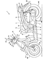
以下、図面を参照して本発明の一実施形態を説明する。図2は、本発明の一実施形態に係るメータユニットを有するスクータ型自動二輪車の左側面図である。なお、以下の説明では、特に記載しない限り、前後左右等の向きは、車両における向きと同一とする。 Hereinafter, an embodiment of the present invention will be described with reference to the drawings. FIG. 2 is a left side view of a scooter type motorcycle having a meter unit according to an embodiment of the present invention. In the following description, unless otherwise specified, the directions such as front and rear, left and right are the same as those in the vehicle.
図2において、自動二輪車1の車体フレームは、メインフレーム2とシートレール3とを有する。メインフレーム2は車体前部に位置するヘッドパイプ5に先端部を接合され、略垂直に下方に延びている縦部分21と、該縦部分21から水平に延びている水平部分22と、水平部分22から上後方に延びる斜め部分23とからなる側面視U字形状の部材である。このメインフレーム2の斜め部分23にシートレール3の前端が接合される。
In FIG. 2, the body frame of the
ヘッドパイプ5は下端部にフロントフォーク6が結合されたステアリング軸7aを旋回自在に支持し、フロントフォーク6の下端部には前輪WFが軸支され、ステアリング軸7aの上端部にはバーハンドル7が取付けられる。ハンドル7の両端にはグリップ7bが取り付けられる。メインフレーム2の後部にはエンジン8を前部に備えたパワーユニット9の前部を枢軸10で上下揺動自在に支持させ、パワーユニット9の後部はシートレール3から懸架させたリアクッション11に連結される。
The head pipe 5 rotatably supports a
パワーユニット9は、エンジン8の出力を変速および減速する周知の構成を有する図示しない変速機および減速機を備え、減速機の出力軸(図示せず)には後輪WRが取り付けられる。シートレール3上には乗員シートおよび同乗者シートを一体に形成したタンデムシート12が載せられる。タンデムシート12の下方には燃料タンク13を配置すると共にヘルメット14を収納することができる収納ボックス15を配置する。
The power unit 9 includes a transmission and a speed reducer (not shown) having a known configuration for shifting and decelerating the output of the
バーハンドル7は、左右端のグリップ部分を除いてハンドルカバー16で周囲を覆われる。ハンドルカバー16は、詳細を後述する前カバー17および後カバー18からなり、前カバー17にはヘッドライト20が組み込まれ、後カバー18にはメータユニット(後述)が組み込まれる。ハンドルカバー16の前カバー17にはヘッドライト20を装着するためのヘッドライト開口を有し、後カバー18には、メータユニットを装着するためのメータユニット開口が形成される。
The bar handle 7 is covered with a
メータユニットおよびヘッドライト20の両側(両サイド)には、前カバー17および後カバー18とは別体で形成された左右1対のサブカバー19が設けられる。つまり、前カバー17、後カバー18およびサブカバー19は、互いに別部品である。サブカバー19は、互いに車体前後に分離して配置されるメータユニットとヘッドライト20とに前後端が隣接するように前カバー17から後カバー18に亘る範囲で延在する部品である。
A pair of left and
前カバー17の左右両端には、ミラー24が配置され、ヘッドライト20およびメータユニットの上辺に接するメータバイザ25の上には、ウィンドスクリーン26が配置される。このウィンドスクリーン26は、サブカバー19を上下に貫通して設けられる左右1対のウィンドスクリーンステー(図6、7を参照して後述)に取り付けられる。
ヘッドパイプ5およびメインフレーム2の一部を囲むフロントカバー27およびレッグシールド28が設けられ、メインフレーム2の残部を囲むステップフロア29およびアンダカバー31が設けられる。また、シートレール3を囲む車体サイドカバー32および車体リヤカバー33が設けられる。
A
フロントフォーク6には、ブレーキキャリパ30が設けられる。前輪WFの上側にはフロントフェンダ34が設けられ、後輪WRの上側にはリヤフェンダ36が設けられる。パワーユニット9の上方には、エンジン8に導入される空気を清浄にするエアクリーナ37が配置される。
A
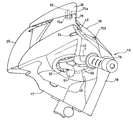
次に、自動二輪車の要部つまりハンドル周りを、図面を参照して詳述する。図1はハンドルカバー16を含む自動二輪車1の要部上面図、図3は同正面斜視図、図4は同後方斜視図、図5は同左側面図である。これらの図において、同符号は同一部分を示す。ハンドルカバー16は、前カバー17および後カバー18からなり、ハンドルカバー16には、サブカバー19、ヘッドライト20、メータユニット38およびメータバイザ25が装着される。前カバー17の後端部と後カバー18の前端部とは突き合わされて境界線40を形成している(図1、図5参照)。
Next, the main part of the motorcycle, that is, the periphery of the handle will be described in detail with reference to the drawings. 1 is a top view of the main part of the
また、図1に示すように、サブカバー19は、左右外側面が前カバー17および後カバー18に面し、前端面がヘッドライト20の左右上端面に対向する。一方、左右内側面はメータバイザ25の側面に面し、後端面がメータユニット38の左右前端面に対向している。つまり、サブカバー19は、前後カバー17、18並びにヘッドライト20、メータユニット38およびメータバイザ25に隣接して配置されている。
As shown in FIG. 1, the sub-cover 19 has the left and right outer surfaces facing the
すなわち、ハンドルカバー16を構成する前カバー17および後カバー18並びにヘッドライト20、メータユニット38およびメータバイザ25等、互いに別体の部品を、これらのすべてと隣接するサブカバー19を設けることによって、一つのまとまりを生じさせている。特に、サブカバー19の前後をヘッドライト20およびメータユニット19に対面当接させることにより、車体の前後方向で離間して配置されているこれら二つの部品に一体感をもたせることができる。
That is, the
前カバー17および後カバー18の境界線40は、前カバー17の前傾面と後カバー18の後傾面とが会合して頂部(もしくは稜線)をなしており、サブカバー19も、この頂部を跨ぐように側面視で頂部を有した山形をなしている(図5参照)。
The
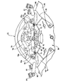
図4において、後カバー18の左側部分には、上方から順にディマースイッチ41、ホーンスイッチ42、および方向指示スイッチ43が設けられる。また、後カバー18の右側部分には、上部にエンジン停止スイッチ44、下部にスタータスイッチ45がそれぞれ設けられる。これらスイッチ41〜45は、後カバー18に形成される開口からスイッチの操作部が後方つまりシート12に座る乗員側に臨むように取り付けられる。
In FIG. 4, a
図1には、前記スイッチ41〜45を取り付ける前のハンドルカバー16を示しており、後カバー18に形成されたスイッチ41〜45の装着用開口のうち、ディマースイッチ41用の開口46、ホーンスイッチ42用の開口47、エンジン停止スイッチ44用の開口48が見られる。後カバー18には、ブレーキオイルにブレーキオイルを供給するマスターシリンダ(図示しない)のオイル量確認用開口49、49が設けられる。
FIG. 1 shows the
後カバー18の左右側面には、バーハンドル7が貫通して左右両側にグリップ部分が張り出せるようにハンドル用の開口50が形成される(図4参照)。バーハンドル7のグリップ部分には、それぞれグリップ7b、7bが取り付けられる(図3参照)。
On the left and right side surfaces of the
また、前カバー17の左右側面には、図3、図5に示すように、ブレーキレバー51が貫通して左右両側に張り出せるようにブレーキレバー用の開口52が形成される。さらに、前カバー17の後部には、ミラー24を支持するミラーステー53が貫通可能な開口54が形成される。この開口は境界線40側に開いたU字型をなしている。
Further, as shown in FIGS. 3 and 5, an
後カバー18は、図1、図4に示すように後方部(図中下部)が狭く、前方部(図中上部)方向に向けて左右方向幅が拡大されたV字型縁55を有し、後述するブリッジ72(図6参照)の縁とともにメータユニット装着用の開口を形成している。そして、このV字型縁55に後面(図中下側面)が沿うようにメータユニット38が配置される。
As shown in FIGS. 1 and 4, the
図3において、ヘッドライト20は、上縁がメータバイザ25およびサブカバー19の前縁に対面当接し、さらに左右および下方が前カバー17に対面当接している。ヘッドライト20は、リフレクタ56を備え、リフレクタ56の焦点位置にはバルブ57を配置している。ヘッドライト20の前面はレンズ58で覆われる。
In FIG. 3, the
前カバー17および後カバー18には、両者を互いに結合する際に使用されるボスや、両者をそれぞれヘッドライト20やメータユニット38に結合する際に使用されるボス等が形成される。
The
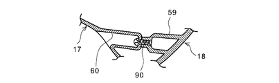
ハンドルカバー16の下端寄りは、ステアリング軸7aを取り囲むように筒状体になっている。図4において、前記ハンドルカバー16の筒状体の後半分を形成する後カバー18の下端寄りには、前カバー17側に突出するボス59が形成されている。そして、図3に示すように、前カバー17には、後カバー18の前記ボス59に対向する位置に、後カバー18に向けて止めねじが貫通可能な孔を有する凹部60が形成される。
Near the lower end of the
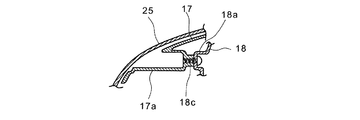
前カバー17の、ヘッドライト20の左右には、後カバー18側に突出するボス63が形成される。このボス63には、ヘッドライト20から左右に張り出すブラケット(図示せず)を後カバー18側から通すことができる止めねじ(図示せず)がねじ込まれる。また、前カバー17には、後カバー18側に突出するボス17aが形成され、このボス17aは、後カバー18から前カバー17側に突出するボス18a(後述)の先端部が対向する。また、前カバー17には、ヘッドライト20の上部に形成されるブラケット79の孔を通すことができる止めねじがねじ込まれるボス67が形成される。
図4において、後カバー18には、メータユニット38の後方側壁に対応する位置に、メータ38側に突出するボス61が形成される。このボス61には、メータユニット38に形成されるステー38A(図10に関して後述)の孔にメータユニット38側から通すことができる止めねじがねじ込まれる。さらに、後カバー18には、オイル量確認開口49に隣接して、前カバー17側に突出するボス62が形成される。このボス62は、後カバー18をバーハンドル7に結合するために設けられる(結合態様は図7に関して後述)。
In FIG. 4, the
メータバイザ25は、2本の止めねじ66によって後カバー18に取り付けられる。図3に示すように、後カバー18には、止めねじ66がねじ込まれるねじ孔を有するステー77が左右一対設けられる(図3、図6参照)。
The
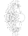
図6は、メータバイザ25および前カバー17を取り外した状態を示すハンドルカバー16の後方斜視図、図7は、後カバー18の要部内側を示す斜視図であり、図1〜5と同符号は同一部分を示す。図1、図5、および図6において、サブカバー19はメータバイザ25に面する側に張り出したステー19aを有しており、前カバー17および後カバー18に面する側には、下向きに張り出した垂下爪19b、19c、および19dを有している。ステー19aは孔64を有しており、この孔64には、図5に示すように下方から止めねじ65を通し、この止めねじ65をメータバイザ25に設けられたボス25aにねじ込んで、サブカバー19をメータバイザ25に結合する。前カバー17の、サブカバー19の左右外側に面する縁には、前記垂下爪19b、19cを上方から差し込める位置に、図示しない2つの溝が形成され、後カバー18の縁には前記垂下爪19dを上方から差し込める位置に、図示しない1つの溝が形成される。したがって、メータバイザ25とサブカバー19とが一体化されたアセンブリは、前記垂下爪19b、19c、19dを、それぞれに対応する前ケース17および後ケース18の溝に上方から差し込むことで、このアセンブリは前ケース17および後ケース18に係合させられる。
6 is a rear perspective view of the
図6において、メータユニット38の上部には、インジケータ表示部68が設けられる。インジケータ表示部68は、左右方向に1列に配置された方向指示表示部69、70、および方向指示表示部69、70の間に配置されるヘッドライト20の点灯状態表示部71を備える。
In FIG. 6, an
後カバー18の一部分はメータユニット38の左右から中央部に延びてインジケータ表示部68の前方を横切るブリッジ72を有しており、このブリッジ72は、該ブリッジ72をメータユニット38の下ケース106のステー73(図12に関して後述)に結合するために使用されるボス74が前方に突出して形成される。ブリッジ72は、ボス74を貫通して前記ステー73にねじ込まれる止めねじ75を通す孔76と、メータバイザ25をブリッジ72に結合するため2個所に設けられ、止めねじ(図10参照)が貫通可能な孔付きのボス18aとを備える。
A portion of the
ボス18a、18aのさらに左右外側には、ステー77、77が立設されている。このステー77は、メータバイザ25を後カバー18に前記止めねじ66、66(図4参照)で取り付けるためのねじ孔を有している。
Stays 77 and 77 are erected on the left and right outer sides of the
ヘッドライト20の一部を形成するヘッドライトハウジング78には、該ハウジング78をメータバイザ25に取り付けるためのブラケット79が突出している。また、サブカバー19には、ウィンドスクリーン26を支持するウィンドスクリーンステー80がそれぞれ貫通して設けられる。ウィンドスクリーンステー80は、前方に向けて4個所にウィンドスクリーン26を取り付ける留め具81を有している。
A
図7において、バーハンドル7には、前方に向けてブラケット82が接合されており、該ブラケット82には、さらに上方に伸びて別のブラケット83が接合されている。サブカバー19を貫通しているウィンドスクリーンステー80の下端部にはブラケット84が接合されており、このブラケット84をハンドル側のブラケット82にボルト結合することによって、ウィンドスクリーン26をバーハンドル7に結合させる。符号85はブラケット84側から挿入されるボルト、符号86はブラケット82の下面に接合されているナットである。
In FIG. 7, a
ブラケット83は、後カバー18に形成されているボス62の前端面に対向しており、ブラケット83を通して止めねじ87をボス62にねじ込むことにより、後カバー18をバーハンドル7に結合される。符号88は方向指示スイッチ43のための取付孔である。また、符号89は、ステアリング軸7aにバーハンドル7を連結するための連結部材である。
The
図8は、前カバー17のボス63の断面図である。ボス63には、止めねじ(タッピングねじ)をねじ込む孔63aが形成されている。
FIG. 8 is a cross-sectional view of the
図9は、前カバー17に形成される凹部60の断面図であり、後カバー18のボス59を併せて示す。前カバー17の凹部60の底部には止めねじ90が貫通可能な孔が形成されており、一方、後カバー18に形成されているボス59には、この止めねじ90をねじ込むねじ孔が形成される。したがって、前カバー17側から止めねじ90を挿入して後カバー18のボス59にねじ込むことにより、前カバー17と後カバー18とを結合することができる。
FIG. 9 is a cross-sectional view of the
図10は、前カバー17のボス17aと後カバーのボス18aとの対向部の断面図である。図10において、メータバイザ25で覆われた前カバー17の部分には、ボス17aが後カバー18側に突出している。このボス17aの先端は、後カバー18の側に形成されたボス18aの先端に対向している。後カバー18側のボス18aには止めねじ18cが貫通する孔が形成され、前カバー17側のボス17aには、止めねじ18cがねじ込まれるねじ孔が形成される。この構成により、止めねじ18cを後カバー18側からボス18aを通してボス17aのねじ孔にねじ込み、前カバー17と後カバー18とを結合することができる。
FIG. 10 is a cross-sectional view of the facing portion between the
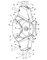
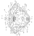
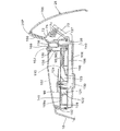
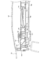
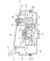
次に、メータユニット38およびメータバイザ25を詳述する。図11はメータユニット38の正面図、図12はメータユニット38の底面図、図13は図11のA−A矢視断面図、図14は図11のB−B矢視断面図、図15は図11のC−C矢視断面図、図16は図11のD−D矢視断面図、図17は図11のE−E矢視断面図である。
Next, the
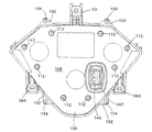
図11において、正面視で外径が略逆三角形に形成されるメータユニット38は、計器部91と、計器部91の前方に位置するインジケータ表示部68とからなる。計器部91には、速度計92、残燃料計93、冷却水温計94、走行距離計95、および時計96を含む。速度計92はメータユニット40の中央後方寄り(図11では下寄り)、残燃料計93はメータユニット38の右前方寄り(図11では右上寄り)、冷却水温計94はメータユニット38の左前方寄り(図11では左上寄り)、走行距離計95および時計96は残燃料計93および冷却水温計94のほぼ中間部に、それぞれ配置される。
In FIG. 11, the
したがって、メータユニット38は、全体的に速度計92が配置される後方部で左右幅が狭く、複数の計器が左右方向に整列されている前方部で左右幅が広い逆三角形をなしており、特に、計器部91は、残燃料計93と冷却水温計94の指針を旋回可能にするため、左右前方(図11では左右上方)に張り出させた領域38a、38bを有する変形逆三角形となっている。そして、領域38aおよび30bの間、つまり張り出し部間に、インジケータ表示部68が設けられる。
Accordingly, the
計器部91には、計器の他、オイル異常インジケータ97、およびABSインジケータ98、およびイモビライザインジケータ99が設けられる。また、メータユニット38の上面の左側には、走行距離計95にトリップ表示をさせるための操作部100が設けられ、右側には、時計設定用の操作部101が設けられる。
In addition to the instrument, the
メータユニット38のケースは上ケース102および下ケース(後述)からなり、操作部100、101は、上ケース102のうち、左右縁から速度計92側に張り出した部分103、104に設けられるゴム製の部品である。また、上ケース102はインジケータ表示部68を形成するための張り出し部分105を有している。張り出し部分103、104および105は、メータユニット38の側部から内側に向けて張り出している水平部(図11に表されている部分103、104)と、この水平部103、104から下方、つまり文字板110上に垂下している見返し部134を有する。水平部つまり張り出し部分103、104および105は、見返し部134を含めてメータユニット38の計器部91を覆う透明レンズ107とは異なり、不透明部材で形成される。
The case of the
メータユニット38のレンズ107の周囲は、図11における上部(つまり車体前方側部分)が張り出し部分105に隣接しているとともに、左右および下部に、レンズ107上面から1段下がった段差面107aを有しており、ハンドルカバー16(前カバー17、後カバー18)の縁部がこの段差面107aに重なるように構成されている。
In the periphery of the
なお、メータユニット38の下ケース106の側部には、一対のステー38Aが設けられる。このステー38Aは、後カバー18のボス62(図4参照)に対向し、ステー38A側から通すことができる止めねじ(図示せず)をボス62にねじ込んでメータユニット38を後カバー18に固定する際に利用される。
A pair of
メータユニットの構成を、断面図を参照してさらに説明する。図13〜16において、メータユニット38のケースは上ケース102、下ケース106およびレンズ107からなる。レンズ107と上ケース102とは互いにインサート成形によって接合される。下ケース106の前上方(図13では右上側)には、ステー73が張り出しており、このステー73を後カバー18のブリッジ72に形成されたボス74を貫通させる止めねじ75を使って結合する。こうして、メータユニット38は、このステー73と前記ステー38Aとを後カバー18に止めねじで結合して後カバー18(ブリッジ72)に保持させる。
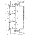
The configuration of the meter unit will be further described with reference to a sectional view. 13 to 16, the case of the
レンズ107は上ケース102に嵌合され、上ケース102と下ケース106との間の空間には、回路基板(以下、単に「基板」という)108、インナケース109、文字板110が設けられる。
The
基板108は、下ケース106から上方に向けて突出しているリブ111上に保持され(図15、図16参照)、複数の止めねじ112によって下ケース106に取り付けられる。なお、止めねじ112は、下ケース106および基板108を貫通し、インナケース109にねじ込まれている。これによって、基板108とインナケース109は下ケース106に共締めされる。全ての止めねじ112をメータ38の裏面側に配置でき、しかも基板108およびインナケース109を共締めができるので、組み立て性がよい。すなわち、上ケース102と下ケース106の締め付けも含めて、全ての止めねじ112、154をメータ裏面側から締め付けられるので、両面からねじ止めする場合のようにメータユニット38を反転させる手間を省略することができる。なお、文字板110は、上方から止めねじ113を使ってインナケース109に取り付けられる。
The
基板108の上には、文字板110に光を裏面から照射して文字板110上の表示を明りょうにするLED(発光ダイオード)114、115、116、117、118、119、120、および121が設けられる。
On the
図15において、LED114は、速度計92の外周部を照射するものであり、インナケース109に形成される導光路123で限定される領域に光を照射する。また、LED115は、速度計92の内周(つまり速度計指針124の中心部)に光を照射するものであり、インナケース109によって囲まれた導光路125で限定される領域に光を照射する。このようにLED114および115によって速度計92の表示領域が文字板1110の裏面から照射される。
In FIG. 15, the
図15において、基板108の裏面には、基板108上の部品に外部電源から給電したり、スイッチ132等の検知信号を出力したりするための端子145が設けられたソケット146が設けられる。ソケット146は、下ケース106に形成されたソケット用開口147を貫通しており、図示しないプラグと結合可能になっている。
In FIG. 15, a
図14、16において、LED116は、冷却水温計94の外周部を照射するものであり、インナケース109によって囲まれた導光路126で限定される領域に光を照射する。また、LED117は、冷却水温計94の内周(つまり冷却水温計指針127の中心部)に光を照射するものであり、インナケース109に形成される導光路128で限定される領域に光を照射する。
14 and 16, the
図14において、LED118は、オイル異常インジケータを照射するものであり、インナケース109によって囲まれた導光路129を通って文字板110に形成されたオイル異常表示用の透明部(図11に記載したオイル異常インジケータ)97を裏面から照明する。また、LED119は、走行距離計95および時計96のバックライトである。さらに、LED120は、文字板110上のABSインジケータ98を裏面から照明する。
In FIG. 14, an
図13において、LED121は、インナケース109によって囲まれた導光路122を通って文字板110上のイモビライザインジケータ99を裏面から照明する。
In FIG. 13, the
速度計92および冷却水温計94は、駆動部130、131および駆動部130、131でそれぞれ回動される指針124、127からなる。残燃料計93も同様の駆動部および指針を有する。
The
図15、図16において、基板108には、速度計92にトリップ表示をさせる操作を検知するスイッチ132が設けられる。スイッチ132の検知部上には、インナケース109で上下動自在に保持されたロッド133が設けられ、このロッド133の上には、前記操作部100の下端が位置している。この構成により、操作部100を上方から押圧操作すると、操作部100は下方に変位してロッド133が押され、この動作でスイッチ132がオン動作する。図示しないが、同様のスイッチやロッドが、時計96の設定を行う操作部101に対応して設けられる。
15 and 16, the
操作部100が設けられている上ケース102の張り出し部分103は、見返し部(つまり垂直壁)134を有しており、この垂直壁134があることによって、スイッチ132の操作部、つまり操作部100の下部分やロッド133およびロッド133を支持するインナケース109の部分等がレンズ107を通して外部から見えないようにして外観の煩雑さを回避している。
The overhanging
前記ロッド133を支持するインナケース109の部分は文字板110を上下に貫通する孔を有している。この孔は、文字板110の領域内に操作子100、101等を配置しやすいように、外周側から内側に向けて形成した切り欠き部であってもよい。
The portion of the
また、垂直壁134によって速度計92が設けられた領域と冷却水温計94が設けられた領域38bとを明りょうに区画することができる。操作部101が設けられる上ケース102の張り出し部分104やインジケータ表示部68にも、同様に見返し部が設けられ、垂直壁34と同様の機能を有する。
Moreover, the area | region in which the
張り出し部分103および張り出し部分104の前縁103a、103bおよび後縁103b、104bは、後カバー18に形成された屈曲面を示す線170、171や172、173と連続して、メータユニット38と後カバー18との連続性を感じさせる特有の外観を呈している(図4参照)。
The
上ケース102の、張り出し部分105には、垂直壁135と、さらに内側の垂直壁136とが設けられ、これら垂直壁135、136および上ケース102の外壁137で囲まれた領域にインジケータ表示部68が形成される。つまり、張り出し部分105の水平部には、3つの開口部158、159、160(図13では160のみ図示、残りは図17参照))にそれぞれレンズ138が嵌め込まれ、レンズ138の下方には、基板108とは別個に、基板108より上位にLED基板140が設けられ、該基板140上にLED139が装着される。
The overhanging
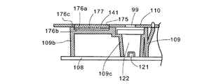
なお、図11、図13に示すように、インナケース109には、速度計92やイモビライザインジケータ99より後方(図11では下側、図13では左側)位置にエンブレム141が設けられる。エンブレム141は、インナケース109の上部に形成されたエンブレム支持凹部176の底面に支持させ、接着等によって接合される。文字板110には、エンブレム支持凹部176にエンブレム141を取り付けるための開口が設けられる。文字板110の開口およびエンブレム141の取り付け態様は、図19、20を参照して後述する。
11 and 13, the
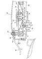
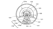
図19は、速度計92の下部および下部に隣接する領域におけるインナケース109の平面図、図20は、図19のG−G矢視図である。図19、図20において、インナケース109は速度計92の中心部を照射する導光路125と、速度計92の指針124の旋回領域つまり速度計192の表示領域124aにLED114の光を導く導光路123と、イモビライザインジケータ99(文字板110に形成した透明部)にLED121の光を導く導光路122とを形成している。
FIG. 19 is a plan view of the
インナケース109は、導光路122の後方(図19では下方)にあって、導光路122や123から隔離されたエンブレム支持凹部176を有する。エンブレム支持凹部176はエンブレム支持面である底部176aと、底部176aから立ち上がる側壁176bと、側壁176bの上端面176cとからなる。導光路122および123から底部176aを隔離する上端面176cは、指針124側から外周側に向けて拡がる略扇型ないしは略三角形をなす。つまり、底部176aは、略扇型ないしは略三角形をなし、エンブレム141の裏面つまり貼り付け面より大きい面積を有する。
The
文字板110に設けられたエンブレム用の開口(文字板開口)175は、エンブレム141の外周形状に沿った内周縁を有する略矩形の開口であり、エンブレム141が、この開口175内を通ることができるように、エンブレム141の外周面との隙間が設定される。エンブレム141は、文字板110の開口175を通して、底部176aに落とし込む。この際、エンブレム141の裏面には接着剤層(または両面接着剤付きテープ)177を介在させる。エンブレム141の厚さは、接着剤177の層も考慮して、表面が文字板110の表面と面一となるように設定したものを使用する。エンブレム141は透明材料で形成され、裏面側にはアルミ蒸着等によりエンブレム141の文字、図形等が形成される。
An emblem opening (dial plate opening) 175 provided in the
文字板110をインナケース109に取り付けた状態では、エンブレム支持凹部176の上端面176cが、文字板110の裏面に密着する。したがって、イモビライザインジケータ99用のLED121の光がエンブレム141側に漏れ出さない。また、エンブレム141の取り付けの際には、文字板110をインナケース109に取り付けた後、文字板110の開口175を通してエンブレム141をエンブレム支持凹部176の底部176aに貼り付けることができる。また、エンブレム141の位置決めは、エンブレム支持凹部176の側壁176bまたは文字板開口175を利用して容易に行うことができる。
In a state where the
なお、図20に示すように、エンブレム支持凹部176を形成するインナケース109は、前記側壁部176bから下方に延出して回路基板108に至る縦部材109bを有し、この縦部材109bは、導光路122を形成する部分と109cとともに、エンブレム支持凹部176および回路基板108を補強する。
As shown in FIG. 20, the
このように、図19、図20に示した実施形態では、速度計192の表示領域124aのうち、表示に使用しない部分、つまり文字板110のうち、指針124が駆動される範囲(範囲124b)以外の空いている領域にエンブレム141を配置することで、メータユニット38を大型化させずにエンブレム141を設けることができる。特に、エンブレム141はインナケース109によって光源であるLED121に対して十分な遮光性が確保されているので、エンブレム141とLED121とを接近させて配置することができ、メータユニット38をより一層小型化できる。
As described above, in the embodiment shown in FIGS. 19 and 20, a portion of the
図17において、インジケータ表示部68を構成するLED基板140は、止めねじ142によって下ケース106に固定される。レンズ138およびLED139は、方向指示用およびヘッドライト点灯表示用にそれぞれ設けられる。上ケース102には、方向指示用およびヘッドライト点灯表示用の区画を限定するための垂直壁143が複数設けられる。そして、レンズ138の上方に対向する部分を除いてインジケータ表示部68を覆うように開口部158、159、160を有するメータバイザ25が装着される。つまり、開口部158、159は、方向指示表示部69、70を見通せるように、開口部160は点灯状態表示部71を見通せるように、各表示部69〜71に対応して設けられる。
In FIG. 17, the
図13〜図17において、上ケース102と下ケース106との合わせ部は、例えば、図16を参照すると、上ケース102の下縁に形成された減厚部148と、減厚部148を両面から挟むように下ケース106の上縁に形成された溝149と、溝149の底部に収められ、組み立てられた状態では溝149の底部に向けて減厚部148で押圧されるシール150とからなる。
13 to 17, for example, referring to FIG. 16, the mating portion of the
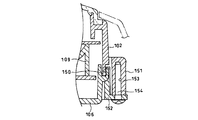
図18は、図11のF−F矢視断面図であり、上ケースおよび下ケースの結合部を示す。図18において、上ケース102から外周に張り出して下ケース106側に延長されたボス151が形成され、下ケース106には上縁から下に延びて、かつその下端部が外側に水平に張り出したブラケット152が形成される。ボス151の下端面はブラケット152の水平張り出し部の上面に対向している。ボス151には、上下に延びたねじ孔153が形成され、ブラケット152の、水平張り出し部には止めねじ154が上下に貫通可能な孔が形成される。この構成により、ブラケット152の、水平張り出し部を下から上に向けて通される止めねじ154が、ボス151のねじ孔153にねじ込まれると、上ケース102と下ケース106はシール150を介して密閉状態で互いに組み立てられる。なお、水平張り出し部を含むブラケット152と止めねじ154は図12にも記載されている。
18 is a cross-sectional view taken along the line F-F in FIG. 11 and shows a coupling portion between the upper case and the lower case. In FIG. 18, a
本発明を、具体的な実施形態を参照して説明したが、本発明はこの実施形態に限定されることなく、当業者は、特許請求の範囲を逸脱しない範囲で変形または応用することができる。例えば、エンブレムの形状は矩形板状のものに限らず、他の形状、例えば、他の多角形や円形の板であってもよい。また、文字板を照射する光源はLEDに限らず、電球であってもよい。また、自動二輪車は、内燃エンジン駆動形式の車両にかぎらず、内燃エンジンと電動モータとを混成使用したハイブリッド型車両や電動車両などのバーハンドルにも同様に適用できる。 Although the present invention has been described with reference to a specific embodiment, the present invention is not limited to this embodiment, and those skilled in the art can make modifications or applications without departing from the scope of the claims. . For example, the shape of the emblem is not limited to a rectangular plate shape, but may be other shapes, for example, other polygonal or circular plates. Moreover, the light source which irradiates a dial plate is not restricted to LED, A light bulb may be sufficient. Further, the motorcycle is not limited to the internal combustion engine drive type vehicle, but can be similarly applied to a bar handle of a hybrid vehicle or an electric vehicle using a mixture of the internal combustion engine and an electric motor.
1…自動二輪車、 7…バーハンドル、 9…パワーユニット、 16…ハンドルカバー、 17…前カバー、 18…後カバー、 20…ヘッドライト、 25…メータバイザ、 26…ウィンドスクリーン、 38…メータユニット、 56…リフレクタ、 109…インナステー、 110…文字板、 141…エンブレム、 175…文字板開口、 176…エンブレム支持凹部、 177…接着剤層
DESCRIPTION OF
Claims (6)
前記インナケース(109)には、前記光照射範囲外で文字板(110)の裏面に対向するエンブレム支持面(176a)が形成され、
前記文字板(110)には、前記エンブレム支持面(176a)に支持されるエンブレムの外側面に対向する縁を有する開口(175)が設けられていることを特徴とする自動二輪車のメータユニット。 Automatic which has dial (110), light source (114-121) which irradiates dial (110) from the back side of dial (110), and inner case (109) which divides the light irradiation range of the light source In the meter unit of a motorcycle,
The inner case (109) is formed with an emblem support surface (176a) facing the back surface of the dial (110) outside the light irradiation range,
The meter unit of the motorcycle, wherein the dial (110) is provided with an opening (175) having an edge facing an outer surface of the emblem supported by the emblem support surface (176a).
前記エンブレム支持部(176)の下部には、前記回路基板(108)上に当接する縦部材(109b)が設けられていることを特徴とする請求項1〜4のいずれかに記載の自動二輪車のメータユニット。 A circuit board (108) in which the light sources (114 to 121) are arranged below the dial (110);
The motorcycle according to any one of claims 1 to 4, wherein a vertical member (109b) that abuts on the circuit board (108) is provided below the emblem support portion (176). Meter unit.
前記インナケース(109)が、前記表示領域(124a)のうち、表示に使用しない一部分を除く範囲に前記光源の(114〜121)照射範囲を区画し、前記一部分に前記エンブレム支持面(176a)が形成されていることを特徴とする請求項1〜5のいずれかに記載の自動二輪車のメータユニット。 The dial (110) includes a circular display area (124a),
The inner case (109) partitions the (114 to 121) irradiation range of the light source in a range excluding a part not used for display in the display area (124a), and the emblem support surface (176a) is formed in the part. The motorcycle meter unit according to claim 1, wherein the meter unit is formed.
Priority Applications (1)
| Application Number | Priority Date | Filing Date | Title |
|---|---|---|---|
| JP2009196733A JP5393349B2 (en) | 2009-08-27 | 2009-08-27 | Motorcycle meter unit |
Applications Claiming Priority (1)
| Application Number | Priority Date | Filing Date | Title |
|---|---|---|---|
| JP2009196733A JP5393349B2 (en) | 2009-08-27 | 2009-08-27 | Motorcycle meter unit |
Publications (2)
| Publication Number | Publication Date |
|---|---|
| JP2011046292A true JP2011046292A (en) | 2011-03-10 |
| JP5393349B2 JP5393349B2 (en) | 2014-01-22 |
Family
ID=43833067
Family Applications (1)
| Application Number | Title | Priority Date | Filing Date |
|---|---|---|---|
| JP2009196733A Expired - Fee Related JP5393349B2 (en) | 2009-08-27 | 2009-08-27 | Motorcycle meter unit |
Country Status (1)
| Country | Link |
|---|---|
| JP (1) | JP5393349B2 (en) |
Cited By (3)
| Publication number | Priority date | Publication date | Assignee | Title |
|---|---|---|---|---|
| JP2013095178A (en) * | 2011-10-28 | 2013-05-20 | Nippon Seiki Co Ltd | Display device |
| JP2015225780A (en) * | 2014-05-28 | 2015-12-14 | 日本精機株式会社 | Switching apparatus |
| JP2020050217A (en) * | 2018-09-27 | 2020-04-02 | 本田技研工業株式会社 | Saddle-type vehicle |
Citations (12)
| Publication number | Priority date | Publication date | Assignee | Title |
|---|---|---|---|---|
| JPH0574967U (en) * | 1992-03-19 | 1993-10-12 | 矢崎総業株式会社 | Instrument lamp cover structure |
| JP2004161151A (en) * | 2002-11-14 | 2004-06-10 | Yns:Kk | Light leakage reducing structure of instrument panel for vehicle |
| JP2007041404A (en) * | 2005-08-04 | 2007-02-15 | Denso Corp | Display device |
| JP2007256003A (en) * | 2006-03-22 | 2007-10-04 | Honda Motor Co Ltd | Instrument display device |
| JP2008203024A (en) * | 2007-02-19 | 2008-09-04 | Nippon Seiki Co Ltd | Display device for vehicle |
| JP2008275378A (en) * | 2007-04-26 | 2008-11-13 | Nippon Seiki Co Ltd | Double molding and anti-fogging agent film formation method of the double molding |
| JP2009068858A (en) * | 2007-09-10 | 2009-04-02 | Denso Corp | Display apparatus |
| JP2009073262A (en) * | 2007-09-19 | 2009-04-09 | Honda Motor Co Ltd | Meter arrangement structure of motorcycle |
| JP2009085664A (en) * | 2007-09-28 | 2009-04-23 | Nippon Seiki Co Ltd | Instrument |
| JP2009151251A (en) * | 2007-12-24 | 2009-07-09 | Denso Corp | Display device |
| JP2009241620A (en) * | 2008-03-28 | 2009-10-22 | Honda Motor Co Ltd | Vehicle speed meter for motorcycle |
| JP2010271557A (en) * | 2009-05-22 | 2010-12-02 | Nippon Seiki Co Ltd | Display device |
-
2009
- 2009-08-27 JP JP2009196733A patent/JP5393349B2/en not_active Expired - Fee Related
Patent Citations (12)
| Publication number | Priority date | Publication date | Assignee | Title |
|---|---|---|---|---|
| JPH0574967U (en) * | 1992-03-19 | 1993-10-12 | 矢崎総業株式会社 | Instrument lamp cover structure |
| JP2004161151A (en) * | 2002-11-14 | 2004-06-10 | Yns:Kk | Light leakage reducing structure of instrument panel for vehicle |
| JP2007041404A (en) * | 2005-08-04 | 2007-02-15 | Denso Corp | Display device |
| JP2007256003A (en) * | 2006-03-22 | 2007-10-04 | Honda Motor Co Ltd | Instrument display device |
| JP2008203024A (en) * | 2007-02-19 | 2008-09-04 | Nippon Seiki Co Ltd | Display device for vehicle |
| JP2008275378A (en) * | 2007-04-26 | 2008-11-13 | Nippon Seiki Co Ltd | Double molding and anti-fogging agent film formation method of the double molding |
| JP2009068858A (en) * | 2007-09-10 | 2009-04-02 | Denso Corp | Display apparatus |
| JP2009073262A (en) * | 2007-09-19 | 2009-04-09 | Honda Motor Co Ltd | Meter arrangement structure of motorcycle |
| JP2009085664A (en) * | 2007-09-28 | 2009-04-23 | Nippon Seiki Co Ltd | Instrument |
| JP2009151251A (en) * | 2007-12-24 | 2009-07-09 | Denso Corp | Display device |
| JP2009241620A (en) * | 2008-03-28 | 2009-10-22 | Honda Motor Co Ltd | Vehicle speed meter for motorcycle |
| JP2010271557A (en) * | 2009-05-22 | 2010-12-02 | Nippon Seiki Co Ltd | Display device |
Cited By (3)
| Publication number | Priority date | Publication date | Assignee | Title |
|---|---|---|---|---|
| JP2013095178A (en) * | 2011-10-28 | 2013-05-20 | Nippon Seiki Co Ltd | Display device |
| JP2015225780A (en) * | 2014-05-28 | 2015-12-14 | 日本精機株式会社 | Switching apparatus |
| JP2020050217A (en) * | 2018-09-27 | 2020-04-02 | 本田技研工業株式会社 | Saddle-type vehicle |
Also Published As
| Publication number | Publication date |
|---|---|
| JP5393349B2 (en) | 2014-01-22 |
Similar Documents
| Publication | Publication Date | Title |
|---|---|---|
| JP5335617B2 (en) | Motorcycle | |
| JP5543665B2 (en) | Vehicle lighting equipment | |
| JP2007269143A (en) | Tail lamp device for vehicle and motorcycle furnished with tail lamp device | |
| JP4630780B2 (en) | Arrangement structure of scooter type vehicles | |
| JP5460182B2 (en) | Motorcycle meter unit | |
| JP2007253836A (en) | Vehicle lamp and motorcycle with vehicle lamp | |
| JP2009166791A (en) | Straddle type vehicle | |
| JP5393349B2 (en) | Motorcycle meter unit | |
| JP2006103361A (en) | Meter device of motorcycle | |
| JP5486175B2 (en) | Taillight device | |
| JP4936316B2 (en) | Waterproof structure for vehicle meter panels | |
| JP5945556B2 (en) | Meter device | |
| JP4994059B2 (en) | Vehicle lighting | |
| JP2015227105A (en) | Mirror device with turn indicator light and saddle-riding type vehicle with the same | |
| JP2013154657A (en) | Vehicular tail light device | |
| JPH07291165A (en) | Integral type electric equipment unit for small-sized vehicle | |
| WO2018180432A1 (en) | Lighting device for saddle-type vehicle | |
| JP4994055B2 (en) | Meter structure | |
| KR101207196B1 (en) | Motorcycle and lamp for vehicle therefor | |
| TWI495590B (en) | Saddle riding type vehicle | |
| JP6426675B2 (en) | Vehicle lighting device | |
| JP6381081B2 (en) | Vehicle lighting equipment | |
| JP5235179B2 (en) | Vehicle lighting | |
| JP5238644B2 (en) | Motorcycle | |
| JP2012101573A (en) | Head lamp device of motorcycle |
Legal Events
| Date | Code | Title | Description |
|---|---|---|---|
| A621 | Written request for application examination |
Free format text: JAPANESE INTERMEDIATE CODE: A621 Effective date: 20111124 |
|
| A521 | Request for written amendment filed |
Free format text: JAPANESE INTERMEDIATE CODE: A523 Effective date: 20120518 |
|
| A977 | Report on retrieval |
Free format text: JAPANESE INTERMEDIATE CODE: A971007 Effective date: 20130513 |
|
| A131 | Notification of reasons for refusal |
Free format text: JAPANESE INTERMEDIATE CODE: A131 Effective date: 20130522 |
|
| A521 | Request for written amendment filed |
Free format text: JAPANESE INTERMEDIATE CODE: A523 Effective date: 20130717 |
|
| TRDD | Decision of grant or rejection written | ||
| A01 | Written decision to grant a patent or to grant a registration (utility model) |
Free format text: JAPANESE INTERMEDIATE CODE: A01 Effective date: 20131009 |
|
| A61 | First payment of annual fees (during grant procedure) |
Free format text: JAPANESE INTERMEDIATE CODE: A61 Effective date: 20131015 |
|
| R150 | Certificate of patent or registration of utility model |
Ref document number: 5393349 Country of ref document: JP Free format text: JAPANESE INTERMEDIATE CODE: R150 Free format text: JAPANESE INTERMEDIATE CODE: R150 |
|
| LAPS | Cancellation because of no payment of annual fees |