JP2011035712A - Image processing device, image processing method and stereoscopic image display device - Google Patents
Image processing device, image processing method and stereoscopic image display device Download PDFInfo
- Publication number
- JP2011035712A JP2011035712A JP2009180646A JP2009180646A JP2011035712A JP 2011035712 A JP2011035712 A JP 2011035712A JP 2009180646 A JP2009180646 A JP 2009180646A JP 2009180646 A JP2009180646 A JP 2009180646A JP 2011035712 A JP2011035712 A JP 2011035712A
- Authority
- JP
- Japan
- Prior art keywords
- parallax
- information
- adjustment
- parallax adjustment
- image processing
- Prior art date
- Legal status (The legal status is an assumption and is not a legal conclusion. Google has not performed a legal analysis and makes no representation as to the accuracy of the status listed.)
- Pending
Links
Images


Landscapes
- Control Of Indicators Other Than Cathode Ray Tubes (AREA)
- Controls And Circuits For Display Device (AREA)
- Testing, Inspecting, Measuring Of Stereoscopic Televisions And Televisions (AREA)
Abstract
Description
本発明は、立体映像をなす一対の画像を入力し、前記一対の画像を補正した画像を生成する画像処理装置に関するものであり、観察者にとって好適な立体映像を得ることを目的としたものである。 The present invention relates to an image processing apparatus that inputs a pair of images forming a stereoscopic image and generates an image obtained by correcting the pair of images, and aims to obtain a stereoscopic image suitable for an observer. is there.
近年、観察者が擬似的に奥行き感を得るための画像表示技術として、両眼視差を利用した立体画像表示技術が多く提案されている。これは、3次元空間を左眼で見た映像と右眼で見た映像をそれぞれ観察者の左右眼に見せることによって、擬似的に奥行き感を誘発する技術である。 In recent years, many stereoscopic image display techniques using binocular parallax have been proposed as image display techniques for an observer to obtain a pseudo-depth feeling. This is a technique for inducing a sense of depth in a pseudo manner by showing an image viewed with the left eye and an image viewed with the right eye to the left and right eyes of an observer, respectively.
観察者の左右眼に異なる映像を見せるための技術として、左眼用画像と右眼用画像を時間的に交互に切り替えてディスプレイに表示すると同時に、画像が切り替わるタイミングに同期して左右それぞれの視界を閉じる眼鏡を用いて左右の視界を時間的に分離する方式や、ディスプレイの前面にディスプレイに表示された画像の表示角を制限するバリアやレンズを用いることで左右眼それぞれに分離して左眼用画像と右眼用画像を見せる方式など、様々な方式が提案されている。 As a technique for showing different images to the left and right eyes of the observer, the left eye image and the right eye image are alternately switched in time and displayed on the display, and at the same time, the left and right fields of view are synchronized with the timing of the image switching. The left eye can be separated into the left and right eyes by separating the left and right fields of view temporally using glasses, or by using a barrier or lens that limits the display angle of the image displayed on the front of the display. Various schemes have been proposed, such as a scheme for displaying a commercial image and a right-eye image.
このような立体画像表示装置においては、観察者が注視している物体が飛び出した点に目の輻輳角を合わせながら、ディスプレイ表面にピントを合わせるという不整合により、飛び出し量が大きすぎると目の疲れを誘発するという問題点がある。また、観察者とディスプレイの表示面との距離や観察者の個人差によって、観察者にとって好適な奥行き感が異なる。 In such a stereoscopic image display device, if the amount of popping out is too large due to the mismatch of focusing on the display surface while adjusting the convergence angle of the eye to the point where the object being watched by the observer pops out, There is a problem of inducing fatigue. Moreover, the depth feeling suitable for the observer varies depending on the distance between the observer and the display surface of the display and the individual differences of the observer.
この問題に対して、特許文献1では、観察者の頭の位置を検出し、検出した頭の位置に応じて遮光部の移動制御を行うことによって観察者にとって最適な立体視を行わせる技術が開示されている。
In order to solve this problem,
また、特許文献2では、立体画像表示時間が所定時間を越えた場合に、立体画像の視差を変更することによって観察者の眼を保護する技術が開示されている。
しかしながら、特許文献1に開示された技術では、観察者の眼の位置に応じた精度の高い光学系の制御が必要とされるため、コストの増大を引き起こす。また、特許文献2に開示された技術では、画像データ全体の水平方向の相対位置を変更することによって視差を小さくして観察者の眼を保護するため、画面全体の立体感を増す、あるいは減らすという変更ができない。また、入力画像にディスプレイ面より手前に表示される画素とディスプレイ面より奥に表示される画素が混在する場合、画像データ全体の視差の絶対値を小さくすることができず、観察者の眼を適切に保護することができない。
However, the technique disclosed in
この発明は、上述のような課題を解消するためになされたもので、入力された画像の一対の画像の視差を、観察者とディスプレイ表面との距離や観察者の個人差によらず、好適な奥行き感の視差に変更して立体画像を表示することを目的とする。 The present invention has been made to solve the above-described problems, and is suitable for the parallax of a pair of images of an input image regardless of the distance between the observer and the display surface or individual differences of the observer. An object is to display a stereoscopic image by changing to a parallax with a sense of depth.
本発明に係わる画像処理装置は、立体映像をなす一対の画像を入力し、前記一対の画像の視差を検出して視差情報を出力する視差情報検出部と、観察者の指示による視差調整情報に基づいて前記視差情報を変更することによって調整後視差情報を生成する視差調整部と、前記調整後視差情報に基づいて、前記一対の画像の視差を変更した新たな一対の画像を生成する画像生成部とを備えることを特徴とする。 An image processing apparatus according to the present invention receives a pair of images forming a stereoscopic image, detects a parallax between the pair of images and outputs parallax information, and parallax adjustment information according to an instruction from an observer. A parallax adjustment unit that generates post-adjustment parallax information by changing the parallax information, and image generation that generates a new pair of images in which the parallax of the pair of images is changed based on the post-adjustment parallax information And a section.
本発明によれば、入力された一対の画像の視差を、観察者の指示による視差調整情報に基づいて視差を変更した一対の画像を生成して表示するようにしたので、観察者とディスプレイ表面との距離や観察者の個人差によらず、観察者にとって好適な奥行き感の立体画像を表示することができる。 According to the present invention, the parallax between the input pair of images is generated and displayed based on the parallax adjustment information instructed by the observer so that the parallax is changed. 3D images with a sense of depth suitable for the viewer can be displayed regardless of the distance between the viewer and the individual difference of the viewer.
実施の形態1.
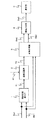
図1は、本発明の実施の形態1に係る立体画像表示装置の構成を示す図である。実施の形態1に係る立体画像表示装置は、視差情報検出部1と、視差調整部2と、画像生成部3と、画像合成部4と、表示部5を備える。
FIG. 1 is a diagram showing a configuration of a stereoscopic image display apparatus according to
入力左眼用画像データDa1と入力右眼用画像データDb1が視差情報検出部1に入力される。視差情報検出部1は、入力左眼用画像データDa1と入力右眼用画像データDb1を比較して画素ごとに視差を検出し視差情報T1を出力する。視差調整部2は、視差調整情報S1に基づいて前記視差情報T1の値を変更し、調整後視差情報T2を出力する。画像生成部3は、入力左眼用画像データDa1と入力右眼用画像データDb1と調整後視差情報T2に基づいて調整左眼用画像データDa2と調整右眼用画像データDb2を生成し出力する。画像合成部4は、調整左眼用画像データDa2と調整右眼用画像データDb2に基づいて合成画像データDa3を生成し出力する。表示部5は、合成画像データDa3に基づいて表示動作を行う。
The input left-eye image data Da1 and the input right-eye image data Db1 are input to the parallax
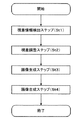
図2は、図1に示す画像処理装置の動作を示すフローチャートである。視差情報検出ステップ(St1)においては、視差情報検出部1により、入力左眼用画像データDa1と入力右眼用画像データDb1を比較して画素ごとに視差が検出され、視差情報T1が出力される。視差調整ステップ(St2)においては、視差調整部2により、視差調整情報S1に基づいて前記視差情報T1の値が変更され、調整後視差情報T2が出力される。画像生成ステップ(St3)においては、画像生成部3により、調整後視差情報T2に基づいて入力左眼用画像データDa1と入力右眼用画像データDb1が変更され、調整左眼用画像データDa2と調整右眼用画像データDb2が出力される。画像合成ステップ(St4)においては、画像合成部4により、調整左眼用画像データDa2と調整右眼用画像データDb2に基づいて合成画像データDa3が生成され、出力される。以上、St1〜St4の各ステップの動作が、入力左眼用画像データDa1と入力右眼用画像データDb1に対し1フレーム毎に行われる。
FIG. 2 is a flowchart showing the operation of the image processing apparatus shown in FIG. In the parallax information detection step (St1), the parallax
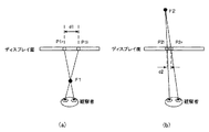
ここで、視差情報検出部1の詳細な動作を説明する。図3は、左眼用画像と右眼用画像の視差と観察者が感じる奥行き感の関係を示すものであり、左眼用画像は観察者の左眼のみに、右眼用画像は観察者の右眼のみに見えるように制御されているものとする。図3には、ディスプレイ面上に表示された左眼用画像の画素と右眼用画像の画素が図示されており、それぞれ左眼用画像の画素をP1l、P2l、右眼用画像の画素をP1r、P2rとする。ディスプレイ面上に表示されたP1lとP1r、及びP2lとP2rにはそれぞれ同じ物体を表示した画素が存在しており、観察者には空間中の点F1、及びF2に物体が存在するように見える。
Here, a detailed operation of the parallax
同じ物体を表示した左眼用画像の画素の水平座標と右眼用画像の画素の水平座標の差分が視差であり、図3(a)では、d1=X(P1l)−X(P1r)、図3(b)ではd2=X(P2l)−X(P2r)と表すことができる。X(P1l)は、P1rの水平座標であり、その他の画素についても同様に表記している。図3(a)では、視差d1は正の値となり、この場合、観察者が注視している画素はディスプレイ面より手前のF1の位置に感じられる。逆に、図3(b)では、視差d2は負の値となり、この場合、観察者が注視している画素はディスプレイ面より奥のF2の位置に感じられる。このように、ここでは、視差は符号付きの値とし、視差が正となる画素はディスプレイ面より手前に、視差が負となる画素はディスプレイ面より奥に表示されることを意味する。 The difference between the horizontal coordinate of the pixel of the left eye image and the horizontal coordinate of the pixel of the right eye image displaying the same object is parallax, and in FIG. 3A, d1 = X (P1l) −X (P1r), In FIG. 3B, it can be expressed as d2 = X (P2l) -X (P2r). X (P1l) is the horizontal coordinate of P1r, and the other pixels are similarly described. In FIG. 3A, the parallax d1 has a positive value, and in this case, the pixel being watched by the observer is felt at the position of F1 in front of the display surface. On the other hand, in FIG. 3B, the parallax d2 has a negative value, and in this case, the pixel being watched by the observer is felt at the position of F2 behind the display surface. Thus, here, the parallax is a signed value, which means that pixels with a positive parallax are displayed in front of the display surface, and pixels with a negative parallax are displayed in the back of the display surface.
視差情報検出部1は、左眼用画像と右眼用画像を比較し、左眼用画像と右眼用画像で同じ物体を表示している画素を検出し、それらの画素の水平座標の差分を計算することで視差を算出する。同じ物体を表示している画素の検出方法としては、例えばブロックマッチングなどの手法を用いることができる。検出した視差は視差情報T1として出力される。
The parallax
次に、視差調整部2の動作を説明する。視差調整部2は、視差調整情報S1に基づいて視差情報検出部1から出力された視差情報T1を変更し、調整後視差情報T2を出力する。
Next, the operation of the
視差調整部2の視差調整方法の一例を説明する。視差調整部2は、前記視差調整情報S1に含まれる視差調整係数C1と視差調整オフセットOS1に従って、下記の式(1)によって調整後視差情報T2を生成する。
T2(x、y)=T1(x、y)×C1+OS1 ・・・・・(1)
T1(x、y)は、水平座標=x、垂直座標=yでの視差情報を、T2(x、y)は、水平座標=x、垂直座標=yでの調整後視差情報を示す。
An example of the parallax adjustment method of the
T2 (x, y) = T1 (x, y) × C1 + OS1 (1)
T1 (x, y) indicates parallax information with horizontal coordinates = x and vertical coordinates = y, and T2 (x, y) indicates post-adjustment parallax information with horizontal coordinates = x and vertical coordinates = y.
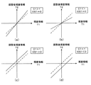
図4は、視差情報T1と調整後視差情報T2の関係を示している。横軸が視差情報T1、縦軸が調整後視差情報T2であり、視差調整係数C1と視差調整オフセットOS1の値別にグラフを示している。また、図4(a)〜(d)に示した破線は視差調整を行わない場合の値であり、実線は各図の右上に示された視差調整情報で視差調整を行った場合の値である。上記式(1)でOS1=0とすると、C1>1の場合には(図4(a))、視差の絶対値が大きくなる。視差の絶対値が大きくなると、ディスプレイ面より手前に感じられていた画素はより手前に、ディスプレイ面より奥に感じられていた画素はより奥に感じられるようになる。つまり、全ての画素がディスプレイ面から離れるように感じられ、画面全体の奥行き感が増す。C1<1の場合には(図4(b))、視差の絶対値が小さくなる。視差の絶対値が小さくなると、ディスプレイ面より手前に感じられていた画素はより奥に、ディスプレイ面より奥に感じられていた画素はより手前に感じられるようになる。つまり、全ての画素がディスプレイ面に近づくように感じられ、画面全体の奥行き感が減る。 FIG. 4 shows the relationship between the parallax information T1 and the adjusted parallax information T2. The horizontal axis is the parallax information T1, the vertical axis is the adjusted parallax information T2, and the graph is shown for each value of the parallax adjustment coefficient C1 and the parallax adjustment offset OS1. Also, the broken lines shown in FIGS. 4A to 4D are values when the parallax adjustment is not performed, and the solid lines are values when the parallax adjustment is performed using the parallax adjustment information shown in the upper right of each figure. is there. If OS1 = 0 in the above equation (1), the absolute value of the parallax increases when C1> 1 (FIG. 4A). As the absolute value of the parallax increases, the pixels that are felt in front of the display surface are felt closer to the front, and the pixels that are felt behind the display surface are felt further back. That is, all the pixels are felt away from the display surface, increasing the depth of the entire screen. In the case of C1 <1 (FIG. 4B), the absolute value of the parallax becomes small. When the absolute value of the parallax is reduced, the pixels that are felt in front of the display surface are felt more deeply, and the pixels that are felt behind the display surface are felt further forward. That is, it is felt that all the pixels are close to the display surface, and the depth feeling of the entire screen is reduced.
また、式(1)において、C1=1とすると、OS1>0の場合には(図4(c))、視差は大きくなる。視差が大きくなると、ディスプレイ面より手前に感じられていた画素と奥に感じられていた画素の両方がより手前に感じられるようになる。つまり、画面全体が手前に飛び出してくるように感じられる。OS1<0の場合には(図4(d))、視差は小さくなる。視差が小さくなると、ディスプレイ面より手前に感じられていた画素と奥に感じられていた画素の両方がより奥に感じられるようになる。つまり、画面全体が奥に引っ込むように感じられる。 In the formula (1), if C1 = 1, the parallax increases when OS1> 0 (FIG. 4C). When the parallax increases, both the pixels that are felt in front of the display surface and the pixels that are felt in the back are felt in front. In other words, it feels like the entire screen pops out. When OS1 <0 (FIG. 4D), the parallax becomes small. When the parallax is reduced, both the pixels that are felt in front of the display surface and the pixels that are felt in the back are felt in the back. In other words, it feels like the entire screen is retracted.
このように、視差調整部2では、視差調整係数C1と視差調整オフセットOS1の二つの視差調整情報に基づいて視差情報T1を変更することで、観察者が感じる奥行き感を変更する。また、図4では、視差調整係数C1、および視差調整オフセットOS1の4通りの組み合わせの例を示したが、これらの組み合わせに限るものではない。
As described above, the
次に、画像生成部3の動作を説明する。画像生成部3は、視差調整部2から出力された調整後視差情報T2に基づいて、入力左眼用画像Da1と入力右眼用画像Db1を変更する。図5は、視差の調整量と奥行き感の変化の関係を示すものであり、図5(a)は図3(a)と同様である。図5(b)は、画像生成部3によって調整された後のスクリーン上に示される画素と観察者が感じる物体の位置を示している。図5(a)に示されたディスプレイ面上に表示された左眼用画像の画素P1lと右眼用画像の画素P1rの視差d1が、視差調整部2の処理によって、d1´に変更されたとすると、画像生成部3は、図5(b)に示すように、視差がd1´になるように左眼用画像の画素P1l´と右眼用画像の画素P1r´を生成する。図5に示すように、調整後視差情報T2によって左眼用画像と右眼用画像を変更することによって、観察者には空間中の点F1´に物体があるように感じられる。すなわち、ΔFだけ物体が奥に移動したように感じられる。
Next, the operation of the
上記のように、画像生成部3は、画素ごとに視差調整情報T2、及び入力左眼用画像Da1と入力右眼用画像Db1に基づいて新たな左眼用画像と右眼用画像を生成し、調整左眼用画像Da2と調整右眼用画像Db2を出力する。
As described above, the
次に、画像合成部4の動作を説明する。画像合成部6は、表示部5の立体画像表示方法に合わせて、調整左眼用画像データDa2と調整右眼用画像データDb2を合成し、合成画像データDa3を出力する。立体表示を可能にする表示部5の方式としては、空間的に異なる座標に左眼用画像と右眼用画像を表示する方式や、時間的に異なるフレームに左眼用画像と右眼用画像を表示する方式などがあるが、画像合成部6は、表示部5の表示方式に応じて両眼の画像を合成する。
Next, the operation of the image composition unit 4 will be described. The image composition unit 6 synthesizes the adjusted left-eye image data Da2 and the adjusted right-eye image data Db2 in accordance with the stereoscopic image display method of the
このように、入力左眼用画像と入力右眼用画像から視差情報を検出し、検出した視差情報と視差調整情報に基づいて入力左眼用画像と入力右眼用画像を変更することによって、画面全体の奥行き感を増加させる、あるいは減少させることができるため、観察者にとって最適な奥行き感の立体画像を表示することができる。 Thus, by detecting the parallax information from the input left-eye image and the input right-eye image, and changing the input left-eye image and the input right-eye image based on the detected parallax information and the parallax adjustment information, Since the depth feeling of the entire screen can be increased or decreased, it is possible to display a stereoscopic image having a depth feeling that is optimal for the observer.
また、入力左眼用画像と入力右眼用画像から視差情報を検出し、検出した視差情報と視差調整情報に基づいて入力左眼用画像と入力右眼用画像を変更することによって、画面全体の奥行き感を増加させる、あるいは減少させることができるため、精度の高い光学系の制御を必要とせず、コストの増大を引き起こさない。 In addition, by detecting the parallax information from the input left-eye image and the input right-eye image, and changing the input left-eye image and the input right-eye image based on the detected parallax information and the parallax adjustment information, the entire screen Therefore, it is not necessary to control the optical system with high accuracy and the cost is not increased.
ここで、視差調整部2の視差調整方法の別の動作例を説明する。図4では、視差調整係数C1と視差調整オフセットOS1に従って、前記式(1)によって調整後視差情報T2を生成する例を示したが、視差調整部2では、前記視差情報の正負によって、異なる視差調整係数、および視差調整オフセットを用いて調整後視差情報T2を生成しても良い。
Here, another operation example of the parallax adjustment method of the
この動作例の場合、前記視差調整部2は、正側の視差調整係数C1と正側の視差調整オフセットOS1、および負側の視差調整係数C2と負側の視差調整オフセットOS2に従って、下記の式(2)によって調整後視差情報T2を生成する。
T2(x、y)=T1(x、y)×C1+OS1 (T1(x、y)>=0)
T2(x、y)=T1(x、y)×C2+OS2 (T1(x、y)<0)
・・・・・・・・・・(2)
T1(x、y)は、水平座標=x、垂直座標=yでの視差情報、T2(x、y)は、水平座標=x、垂直座標=yでの調整後視差情報を示す。
In the case of this operation example, the
T2 (x, y) = T1 (x, y) × C1 + OS1 (T1 (x, y)> = 0)
T2 (x, y) = T1 (x, y) × C2 + OS2 (T1 (x, y) <0)
(2)
T1 (x, y) indicates parallax information with horizontal coordinates = x and vertical coordinates = y, and T2 (x, y) indicates post-adjustment parallax information with horizontal coordinates = x and vertical coordinates = y.
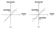
図6は、この動作例の場合の視差情報T1と調整後視差情報T2の関係の一例を示しており、グラフ軸、および実線と破線の意味は図4と同様である。図6(a)は、上記式(1)において、C1<1、OS1=0、C2=1、OS2=0とした場合の視差情報と調整後視差情報の関係を示している。この場合、視差情報が正、つまりディスプレイ面より手前に感じられていた画素が、より奥に移動しディスプレイ面に近づくように感じられる。視差情報が負、つまりディスプレイ面より奥に感じられていた画素は変化しない。また、図6(b)は、上記式(1)において、C1=1、OS1=0、C2>1、OS2=0とした場合の視差情報と調整後視差情報の関係を示している。この場合、視差情報が負、つまりディスプレイ面より奥に感じられていた画素が、より奥に移動しディスプレイ面から遠ざかるように感じられる。視差情報が正、つまりディスプレイ面より手前に感じられていた画素は変化しない。 FIG. 6 shows an example of the relationship between the parallax information T1 and the adjusted parallax information T2 in the case of this operation example, and the meanings of the graph axes and the solid and broken lines are the same as those in FIG. FIG. 6A shows the relationship between the parallax information and the adjusted parallax information when C1 <1, OS1 = 0, C2 = 1, and OS2 = 0 in the above formula (1). In this case, it is felt that the parallax information is positive, that is, the pixel that was felt in front of the display surface moves further back and approaches the display surface. Pixels in which the parallax information is negative, that is, the pixels felt behind the display surface do not change. FIG. 6B shows the relationship between the parallax information and the adjusted parallax information when C1 = 1, OS1 = 0, C2> 1, and OS2 = 0 in the above equation (1). In this case, it is felt that the parallax information is negative, that is, the pixels that were felt behind the display surface move further away from the display surface. The pixel that the parallax information is positive, that is, the pixel that was felt in front of the display surface does not change.
このように、視差調整部2では、正側の視差調整係数C1と正側の視差調整オフセットOS1、および負側の視差調整係数C2と負側の視差調整オフセットOS2の四つの視差調整情報に基づいて視差情報T1を変更することで、ディスプレイ面より手前に感じられていた画素とディスプレイ面より奥に感じられていた画素の奥行き感を独立に調整することが可能である。また、図6では、正側の視差調整係数C1、正側の視差調整オフセットOS1、および負側の視差調整係数C2、負側の視差調整オフセットOS2の2通りの組み合わせの例を示したが、これらの組み合わせに限るものではない。
Thus, the
このように、入力左眼用画像と入力右眼用画像から視差情報を検出し、検出した視差情報の正負によって異なる視差調整情報に基づいて入力左眼用画像と入力右眼用画像を変更することによって、ディスプレイ面より手前に感じられていた画素とディスプレイ面より奥に感じられていた画素を独立して調整することができるため、観察者にとって最適な奥行き感の立体画像を表示することができる。 As described above, the parallax information is detected from the input left-eye image and the input right-eye image, and the input left-eye image and the input right-eye image are changed based on the parallax adjustment information that differs depending on whether the detected parallax information is positive or negative. Therefore, it is possible to independently adjust the pixel that was felt in front of the display surface and the pixel that was felt in the back of the display surface, so that it is possible to display a stereoscopic image with a sense of depth optimal for the observer it can.
次に、視差調整部2の視差調整方法のさらに別の動作例を説明する。図6では、前記視差情報の正負符号によって、異なる視差調整係数と視差調整オフセットを用いて調整後視差情報T2を生成する例を示したが、視差調整部2では、前記視差情報に予め定められた閾値より大きい視差情報が含まれる場合に、対応する画素の視差が前記閾値を超えないように制限した調整後視差情報T2を生成しても良い。
Next, still another operation example of the parallax adjustment method of the
この動作例の場合、前記視差調整部2は、予め定められた閾値H1に従って、下記の式(3)によって調整後視差情報T2を生成する。
T2(x、y)=H1 (T1(x、y)>=H1)
T2(x、y)=T1(x、y) (T1(x、y)<H1) ・・・(3)
T1(x、y)は、水平座標=x、垂直座標=yでの視差情報、T2(x、y)は、水平座標=x、垂直座標=yでの調整後視差情報を示す。
In the case of this operation example, the
T2 (x, y) = H1 (T1 (x, y)> = H1)
T2 (x, y) = T1 (x, y) (T1 (x, y) <H1) (3)
T1 (x, y) indicates parallax information with horizontal coordinates = x and vertical coordinates = y, and T2 (x, y) indicates post-adjustment parallax information with horizontal coordinates = x and vertical coordinates = y.
また、正側の閾値H1と負側の閾値H2を予め定めておき、下記の式(4)によって調整後視差情報T2を生成してもよい。
T2(x、y)=H1 (T1(x、y)>=0かつT1(x、y)>=H1)
T2(x、y)=T1(x、y)(T1(x、y)>=0かつT1(x、y)<H1)
T2(x、y)=T1(x、y)(T1(x、y)<0かつT1(x、y)<H2)
T2(x、y)=H2 (T1(x、y)<0かつT1(x、y)<=H2)
・・・・・・・(4)
T1(x、y)は、水平座標=x、垂直座標=yでの視差情報、T2(x、y)は、水平座標=x、垂直座標=yでの調整後視差情報を示す。
Alternatively, the positive-side threshold value H1 and the negative-side threshold value H2 may be determined in advance, and the adjusted parallax information T2 may be generated by the following equation (4).
T2 (x, y) = H1 (T1 (x, y)> = 0 and T1 (x, y)> = H1)
T2 (x, y) = T1 (x, y) (T1 (x, y)> = 0 and T1 (x, y) <H1)
T2 (x, y) = T1 (x, y) (T1 (x, y) <0 and T1 (x, y) <H2)
T2 (x, y) = H2 (T1 (x, y) <0 and T1 (x, y) <= H2)
.... (4)
T1 (x, y) indicates parallax information with horizontal coordinates = x and vertical coordinates = y, and T2 (x, y) indicates post-adjustment parallax information with horizontal coordinates = x and vertical coordinates = y.
図7は、この場合の動作例での視差情報T1と調整後視差情報T2の関係の一例を示しており、グラフ軸、および実線と破線の意味は図4と同様である。図7(a)は、上記式(3)のように、正側の閾値H1による視差の制限のみを有効にした例である。この場合、ディスプレイ面より手前に感じられていた画素のうち、飛び出し量が一定値より大きい画素の飛び出し量を制限するように動作する。また、図7(b)は、上記式(4)のように、正側の閾値H1と負側の閾値H2による視差の制限を有効にした例である。この場合、ディスプレイ面より手前に感じられていた画素のうち、飛び出し量が一定値より大きい画素の飛び出し量を制限することに加え、引っ込み量が一定値より大きい画素の引っ込み量を制限するように動作する。 FIG. 7 shows an example of the relationship between the parallax information T1 and the adjusted parallax information T2 in the operation example in this case, and the meanings of the graph axes and the solid and broken lines are the same as those in FIG. FIG. 7A shows an example in which only the parallax restriction by the positive threshold H1 is validated as in the above equation (3). In this case, the operation is performed so as to limit the pop-out amount of a pixel whose pop-out amount is larger than a certain value among the pixels felt in front of the display surface. FIG. 7B is an example in which the parallax restriction by the positive threshold H1 and the negative threshold H2 is made effective as in the above equation (4). In this case, in addition to limiting the pop-out amount of pixels whose pop-out amount is larger than a certain value among the pixels felt in front of the display surface, the pull-in amount of pixels whose retraction amount is larger than the predetermined value is limited. Operate.
なお、この動作例では、正側の閾値H1と負側の閾値H2の2通りの組み合わせの例を示したが、これらの組み合わせに限るものではなく、例えば、負側の閾値H2による視差の制限のみを有効にするなどしてもよい。また、前記視差調整係数や前記視差調整オフセットと前記正側の閾値H1、および負側の閾値H2を併用して視差を調整することも可能である。 In this operation example, two examples of combinations of the positive threshold value H1 and the negative threshold value H2 are shown. However, the present invention is not limited to these combinations. For example, the parallax is limited by the negative threshold value H2. You may enable only. It is also possible to adjust the parallax by using the parallax adjustment coefficient or the parallax adjustment offset together with the positive threshold value H1 and the negative threshold value H2.
このように、入力左眼用画像と入力右眼用画像から視差情報を検出し、検出した視差情報の大きさを閾値によって制限することによって得られた視差調整情報に基づいて入力左眼用画像と入力右眼用画像を変更することによって、一定値より大きい飛び出し量、あるいは引っ込み量を制限することができるため、観察者にとって眼の負担となりやすい過度な視差を制限することによって最適な奥行き感の立体画像を表示することができる。 In this way, the input left-eye image based on the parallax adjustment information obtained by detecting the parallax information from the input left-eye image and the input right-eye image and limiting the size of the detected parallax information with the threshold value. By changing the input image for the right eye, it is possible to limit the amount of protrusion or retraction greater than a certain value. 3D images can be displayed.
実施の形態2.
図8は、本発明の実施の形態2に係る立体画像表示装置の構成を示す図である。実施の形態2に係る立体画像表示装置は、視差情報検出部1と、画像生成部3と、画像合成部4と、表示部5と、視差調整情報生成部10と、視差調整部11を備える。ここで、視差情報検出部1と、画像生成部3と、画像合成部4と、表示部5は前述した実施の形態1の立体画像表示装置と同じ動作をするため、ここでは説明を省略する。
FIG. 8 is a diagram showing a configuration of a stereoscopic image display apparatus according to
図9は、図8に示す画像処理装置の動作を示すフローチャートである。視差調整情報生成ステップ(St5)においては、視差調整情報生成部10により、視差情報検出部1から出力された視差情報T1を調整するための視差調整情報S2が生成される。その他のステップは、前述した実施の形態1の各ステップと同じ動作をするため、ここでは説明を省略する。
FIG. 9 is a flowchart showing the operation of the image processing apparatus shown in FIG. In the parallax adjustment information generation step (St5), the parallax adjustment
図10は、視差調整情報生成部10の内部構成を示す図である。視差調整情報生成部10は、奥行調整情報入力部100と、グラフィカルユーザインターフェース生成部101と、視差調整情報出力部102を備える。
FIG. 10 is a diagram illustrating an internal configuration of the parallax adjustment
奥行調整情報入力部100は、例えば観察者がリモコンを操作することにより入力された制御信号に基づいて視差調整入力情報S10を出力する。グラフィカルユーザインターフェース生成部101は、視差調整入力情報S10に従って表示部5にグラフィカルユーザインターフェースを表示するためのグラフィカルユーザインターフェース情報S11を生成する。視差調整情報出力部102は、視差調整入力情報S10に基づいて前記視差情報検出部1から出力された前記視差情報T1を調整するための視差調整情報S2を生成する。
The depth adjustment
図11は、視差調整情報生成部の動作を示すフローチャートである。視差調整情報入力ステップ(St10)においては、観察者の操作に基づいて視差調整入力情報S10が出力される。グラフィカルユーザインターフェース生成ステップ(St11)においては、視差調整入力情報S10に従って表示部5にグラフィカルユーザインターフェースを表示するためのグラフィカルユーザインターフェース情報S11が生成される。視差調整情報出力ステップ(St12)においては、視差調整入力情報S10に基づいて前記視差情報検出部1から出力された前記視差情報T1を調整するための視差調整情報S2が生成される。
FIG. 11 is a flowchart illustrating the operation of the parallax adjustment information generation unit. In the parallax adjustment information input step (St10), the parallax adjustment input information S10 is output based on the operation of the observer. In the graphical user interface generation step (St11), graphical user interface information S11 for displaying the graphical user interface on the
次に、前記視差調整情報生成部10が生成するグラフィカルユーザインターフェースの一例を説明する。図12には、表示ディスプレイ20と、グラフィカルユーザインターフェース21が示されている。図12に示すように、グラフィカルユーザインターフェースはスライドバーの形状をしており、例えば観察者がリモコンを操作してスライドバーの選択部分を左右に動かすことによって前記視差調整情報S2が前記視差調整情報生成部10に入力される。
Next, an example of a graphical user interface generated by the parallax adjustment
図12の例では、図12(a)に示すように、観察者の操作によってグラフィカルユーザインターフェース21がスライドバーの中央が選択された状態になった場合、前記視差調整情報生成部10は、前記視差情報T1を変更しないような前記視差調整情報S2を生成する。また、図12(b)に示すように、観察者の操作によってグラフィカルユーザインターフェース21がスライドバーの左側が選択された状態になった場合、前記視差調整情報生成部10は、視差の絶対値が小さくなるような前記視差調整情報S2を生成する。
In the example of FIG. 12, as illustrated in FIG. 12A, when the
図13には、図12と同様に表示ディスプレイ20と、グラフィカルユーザインターフェース21が示されている。図13(b)に示すように、観察者の操作によってグラフィカルユーザインターフェース20がスライドバーの左端が選択された状態になった場合、前記視差調整情報生成部10は、視差が0になるような前記視差調整情報S2を生成する。
FIG. 13 shows a
前記グラフィカルユーザインターフェース21は、前記正側の視差調整係数C1、正側の前記視差調整オフセットOS1、前記負側の視差調整係数C2、前記負側の視差調整オフセットOS2、前記正側の閾値H1、前記負側の閾値H2をそれぞれ独立に操作できるように、それぞれの値に対応したスライドバーを別々に表示してもよいし、一つのスライドバーを表示し、スライドバーが示す値に基づいて、前記視差調整情報生成部が前記正側の視差調整係数C1、正側の前記視差調整オフセットOS1、前記負側の視差調整係数C2、前記負側の視差調整オフセットOS2、前記正側の閾値H1、前記負側の閾値H2の値を決定してもよい。なお、前記グラフィカルユーザインターフェース21の形状は、スライドバー状であればよく、図12に示した形状や表示位置、または表示文字に限定するものではない。
The
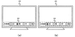
次に、グラフィカルユーザインターフェースのさらに別の例を説明する。図14には、表示ディスプレイ20と、グラフィカルユーザインターフェース22が示されている。図14に示すように、グラフィカルユーザインターフェースは観察者に弱、中、強の中から一つを選ばせる選択肢の形状をしており、観察者が選択肢の中から一つを選択することによって前記視差調整情報S2が前記視差調整情報生成部10に入力される。
Next, still another example of the graphical user interface will be described. FIG. 14 shows a
図14の例では、図14(a)に示すように、観察者の操作によってグラフィカルユーザインターフェース22が中央の選択肢が選択された状態になった場合、前記視差調整情報生成部10は、前記視差情報T1を変更しないような前記視差調整情報S2を生成する。また、図14(b)に示すように、観察者の操作によってグラフィカルユーザインターフェース22が左側の選択肢が選択された状態になった場合、前記視差調整情報生成部10は、視差の絶対値が小さくなるような前記視差調整情報S2を生成する。
In the example of FIG. 14, as illustrated in FIG. 14A, when the
図15にグラフィカルユーザインターフェースのさらに別の例を示す。図15の例では、図14の例で示した選択しに加え、視差を0にする選択肢が追加されたグラフィカルユーザインターフェース23が示されている。図15(b)に示すように、観察者の操作によってグラフィカルユーザインターフェース22が視差を0にする選択肢が選択された状態になった場合、前記視差調整情報生成部10は、視差が0になるような前記視差調整情報S2を生成する。
FIG. 15 shows still another example of the graphical user interface. In the example of FIG. 15, in addition to the selection shown in the example of FIG. 14, a graphical user interface 23 to which an option for setting the parallax to 0 is added is shown. As illustrated in FIG. 15B, when the option to set the parallax to 0 is selected by the
前記グラフィカルユーザインターフェースは、前記正側の視差調整係数C1、正側の前記視差調整オフセットOS1、前記負側の視差調整係数C2、前記負側の視差調整オフセットOS2、前記正側の閾値H1、前記負側の閾値H2をそれぞれ独立に操作できるように、それぞれの値に対応した選択肢を別々に表示してもよいし、一つの選択肢を表示し、選択肢が示す値に基づいて、前記視差調整情報生成部が予め定められた手順に従って前記正側の視差調整係数C1、正側の前記視差調整オフセットOS1、前記負側の視差調整係数C2、前記負側の視差調整オフセットOS2、前記正側の閾値H1、前記負側の閾値H2の値を決定してもよい。なお、前記グラフィカルユーザインターフェースは、選択肢の形状であればよく、図14に示した形状や選択肢数や表示位置、および表示文字に限定するものではない。 The graphical user interface includes the positive parallax adjustment coefficient C1, the positive parallax adjustment offset OS1, the negative parallax adjustment coefficient C2, the negative parallax adjustment offset OS2, the positive threshold H1, The options corresponding to the respective values may be displayed separately so that the negative threshold value H2 can be operated independently, or one option is displayed, and the parallax adjustment information is displayed based on the value indicated by the option. According to a predetermined procedure by the generation unit, the positive-side parallax adjustment coefficient C1, the positive-side parallax adjustment offset OS1, the negative-side parallax adjustment coefficient C2, the negative-side parallax adjustment offset OS2, and the positive-side threshold value H1 and the negative threshold value H2 may be determined. The graphical user interface is not limited to the shape, the number of options, the display position, and the display characters shown in FIG.
このように、入力左眼用画像と入力右眼用画像から視差情報を検出し、検出した視差情報と観察者がグラフィカルユーザインターフェースを操作することによって決定される視差調整情報に基づいて入力左眼用画像と入力右眼用画像を変更することによって、画面全体の奥行き感を増加させる、あるいは減少させることができるため、観察者自らの操作によって、直感的に観察者が最も好ましいと感じる奥行き感の立体画像を表示することができる。 As described above, the parallax information is detected from the input left-eye image and the input right-eye image, and the input left eye is based on the detected parallax information and the parallax adjustment information determined by the observer operating the graphical user interface. The depth feeling of the entire screen can be increased or decreased by changing the image for the right eye and the image for the input right eye. 3D images can be displayed.
1 視差情報検出部、 2 視差調整部、 3 画像生成部、 4 画像合成部、 5 表示部、 10 視差調整情報生成部、 11 視差調整部、 20 表示ディスプレイ、 21 グラフィカルユーザインターフェース、 22 グラフィカルユーザインターフェース、 23 グラフィカルユーザインターフェース、 100 奥行調整情報入力部、 101 グラフィカルユーザインターフェース生成部、 102 視差調整情報出力部。
DESCRIPTION OF
Claims (17)
視差調整情報に基づいて前記視差情報を変更することによって調整後視差情報を生成する視差調整部と、
前記調整後視差情報に基づいて、前記一対の画像の視差を変更した新たな一対の画像を生成する画像生成部を備えることを特徴とする画像処理装置。 A parallax information detection unit that inputs a pair of images forming a stereoscopic video, detects parallax of the pair of images, and outputs parallax information;
A parallax adjustment unit that generates post-adjustment parallax information by changing the parallax information based on parallax adjustment information;
An image processing apparatus comprising: an image generation unit configured to generate a new pair of images in which parallax between the pair of images is changed based on the adjusted parallax information.
前記一対の画像を入力し、当該一対の画像の視差を検出して視差情報を出力する視差情報検出ステップと、
視差調整情報に基づいて前記視差情報を変更することによって調整後視差情報を生成する視差調整ステップと、
前記調整後視差情報に基づいて、前記一対の画像の視差を変更した新たな一対の画像を生成する画像生成ステップを備えることを特徴とする画像処理方法。 In an image processing method for inputting a pair of images forming a stereoscopic image and generating an image obtained by correcting the pair of images,
A parallax information detection step of inputting the pair of images, detecting parallax of the pair of images and outputting parallax information;
A parallax adjustment step of generating adjusted parallax information by changing the parallax information based on parallax adjustment information; and
An image processing method comprising: an image generation step of generating a new pair of images in which the parallax of the pair of images is changed based on the adjusted parallax information.
観察者がグラフィカルユーザインターフェースを操作した結果に基づいて視差調整情報を生成することを特徴とする請求項15に記載の画像処理方法。 A parallax adjustment information generation step, wherein the parallax adjustment information generation step includes a graphical user interface generation step of generating a signal for displaying a graphical user interface; and an observer performing a parallax adjustment operation through the graphical user interface A parallax adjustment information input step,
The image processing method according to claim 15, wherein the parallax adjustment information is generated based on a result of an observer operating a graphical user interface.
Priority Applications (1)
| Application Number | Priority Date | Filing Date | Title |
|---|---|---|---|
| JP2009180646A JP2011035712A (en) | 2009-08-03 | 2009-08-03 | Image processing device, image processing method and stereoscopic image display device |
Applications Claiming Priority (1)
| Application Number | Priority Date | Filing Date | Title |
|---|---|---|---|
| JP2009180646A JP2011035712A (en) | 2009-08-03 | 2009-08-03 | Image processing device, image processing method and stereoscopic image display device |
Publications (2)
| Publication Number | Publication Date |
|---|---|
| JP2011035712A true JP2011035712A (en) | 2011-02-17 |
| JP2011035712A5 JP2011035712A5 (en) | 2012-08-30 |
Family
ID=43764331
Family Applications (1)
| Application Number | Title | Priority Date | Filing Date |
|---|---|---|---|
| JP2009180646A Pending JP2011035712A (en) | 2009-08-03 | 2009-08-03 | Image processing device, image processing method and stereoscopic image display device |
Country Status (1)
| Country | Link |
|---|---|
| JP (1) | JP2011035712A (en) |
Cited By (13)
| Publication number | Priority date | Publication date | Assignee | Title |
|---|---|---|---|---|
| JP2011176823A (en) * | 2010-01-28 | 2011-09-08 | Toshiba Corp | Image processing apparatus, 3d display apparatus, and image processing method |
| JP2012204852A (en) * | 2011-03-23 | 2012-10-22 | Sony Corp | Image processing apparatus and method, and program |
| WO2013128847A1 (en) * | 2012-03-02 | 2013-09-06 | パナソニック株式会社 | Parallax adjustment device, three-dimensional image generator, and parallax adjustment method |
| CN103903591A (en) * | 2012-12-25 | 2014-07-02 | 扬智科技股份有限公司 | Picture adjustment method, device and display device |
| JP2014526823A (en) * | 2011-09-08 | 2014-10-06 | クゥアルコム・インコーポレイテッド | Method and apparatus for improved cropping of stereoscopic image pairs |
| JP2015039075A (en) * | 2011-05-31 | 2015-02-26 | 株式会社東芝 | Stereoscopic image display device, and stereoscopic image display method |
| JP2015041788A (en) * | 2013-08-20 | 2015-03-02 | 日産自動車株式会社 | Two-dimensional and three-dimensional display apparatus |
| JP2015041789A (en) * | 2013-08-20 | 2015-03-02 | 日産自動車株式会社 | Two-dimensional and three-dimensional display apparatus |
| US9094657B2 (en) | 2011-09-22 | 2015-07-28 | Kabushiki Kaisha Toshiba | Electronic apparatus and method |
| JP2015186100A (en) * | 2014-03-25 | 2015-10-22 | 株式会社Jvcケンウッド | Stereoscopic image generation device, stereoscopic image generation method and stereoscopic image generation program |
| JP2015186099A (en) * | 2014-03-25 | 2015-10-22 | 株式会社Jvcケンウッド | Stereoscopic image generation device, stereoscopic image generation method and stereoscopic image generation program |
| CN105469773A (en) * | 2014-09-03 | 2016-04-06 | 富泰华工业(深圳)有限公司 | Display screen brightness adjusting method and system |
| JP2017041887A (en) * | 2012-03-30 | 2017-02-23 | 富士フイルム株式会社 | Image processing system, imaging apparatus, image processing method and program |
Citations (5)
| Publication number | Priority date | Publication date | Assignee | Title |
|---|---|---|---|---|
| JPH09271043A (en) * | 1996-03-29 | 1997-10-14 | Olympus Optical Co Ltd | Stereoscopic image display device |
| JPH1127703A (en) * | 1997-06-30 | 1999-01-29 | Canon Inc | Display device and its control method |
| JP2000092576A (en) * | 1998-09-08 | 2000-03-31 | Fujita Corp | Remote monitoring system |
| JP2004129186A (en) * | 2002-07-31 | 2004-04-22 | Sharp Corp | Device and program for processing stereoscopic image data, and recording medium |
| JP2005073013A (en) * | 2003-08-26 | 2005-03-17 | Sharp Corp | Device and method for stereo image display, program for making computer execute the method, and recording medium recording the program |
-
2009
- 2009-08-03 JP JP2009180646A patent/JP2011035712A/en active Pending
Patent Citations (5)
| Publication number | Priority date | Publication date | Assignee | Title |
|---|---|---|---|---|
| JPH09271043A (en) * | 1996-03-29 | 1997-10-14 | Olympus Optical Co Ltd | Stereoscopic image display device |
| JPH1127703A (en) * | 1997-06-30 | 1999-01-29 | Canon Inc | Display device and its control method |
| JP2000092576A (en) * | 1998-09-08 | 2000-03-31 | Fujita Corp | Remote monitoring system |
| JP2004129186A (en) * | 2002-07-31 | 2004-04-22 | Sharp Corp | Device and program for processing stereoscopic image data, and recording medium |
| JP2005073013A (en) * | 2003-08-26 | 2005-03-17 | Sharp Corp | Device and method for stereo image display, program for making computer execute the method, and recording medium recording the program |
Cited By (16)
| Publication number | Priority date | Publication date | Assignee | Title |
|---|---|---|---|---|
| JP2011176822A (en) * | 2010-01-28 | 2011-09-08 | Toshiba Corp | Image processing apparatus, 3d display apparatus, and image processing method |
| JP2011176823A (en) * | 2010-01-28 | 2011-09-08 | Toshiba Corp | Image processing apparatus, 3d display apparatus, and image processing method |
| JP2012204852A (en) * | 2011-03-23 | 2012-10-22 | Sony Corp | Image processing apparatus and method, and program |
| JP2015039075A (en) * | 2011-05-31 | 2015-02-26 | 株式会社東芝 | Stereoscopic image display device, and stereoscopic image display method |
| US9560334B2 (en) | 2011-09-08 | 2017-01-31 | Qualcomm Incorporated | Methods and apparatus for improved cropping of a stereoscopic image pair |
| JP2014526823A (en) * | 2011-09-08 | 2014-10-06 | クゥアルコム・インコーポレイテッド | Method and apparatus for improved cropping of stereoscopic image pairs |
| US9094657B2 (en) | 2011-09-22 | 2015-07-28 | Kabushiki Kaisha Toshiba | Electronic apparatus and method |
| WO2013128847A1 (en) * | 2012-03-02 | 2013-09-06 | パナソニック株式会社 | Parallax adjustment device, three-dimensional image generator, and parallax adjustment method |
| US20140055579A1 (en) * | 2012-03-02 | 2014-02-27 | Panasonic Corporation | Parallax adjustment device, three-dimensional image generation device, and method of adjusting parallax amount |
| JP2017041887A (en) * | 2012-03-30 | 2017-02-23 | 富士フイルム株式会社 | Image processing system, imaging apparatus, image processing method and program |
| CN103903591A (en) * | 2012-12-25 | 2014-07-02 | 扬智科技股份有限公司 | Picture adjustment method, device and display device |
| JP2015041788A (en) * | 2013-08-20 | 2015-03-02 | 日産自動車株式会社 | Two-dimensional and three-dimensional display apparatus |
| JP2015041789A (en) * | 2013-08-20 | 2015-03-02 | 日産自動車株式会社 | Two-dimensional and three-dimensional display apparatus |
| JP2015186099A (en) * | 2014-03-25 | 2015-10-22 | 株式会社Jvcケンウッド | Stereoscopic image generation device, stereoscopic image generation method and stereoscopic image generation program |
| JP2015186100A (en) * | 2014-03-25 | 2015-10-22 | 株式会社Jvcケンウッド | Stereoscopic image generation device, stereoscopic image generation method and stereoscopic image generation program |
| CN105469773A (en) * | 2014-09-03 | 2016-04-06 | 富泰华工业(深圳)有限公司 | Display screen brightness adjusting method and system |
Similar Documents
| Publication | Publication Date | Title |
|---|---|---|
| JP2011035712A (en) | Image processing device, image processing method and stereoscopic image display device | |
| US8963913B2 (en) | Stereoscopic image display and method of adjusting stereoscopic image thereof | |
| US9204140B2 (en) | Display device and display method | |
| KR101380517B1 (en) | Multi-view autostereoscopic image display and method of controlling optimal viewing distance | |
| TW201405483A (en) | Image data processing method and stereoscopic image display using the same | |
| JP5545036B2 (en) | Image processing apparatus, image processing method, and image display apparatus | |
| JP2011164202A (en) | Image display device, image display system, and image display method | |
| US9167237B2 (en) | Method and apparatus for providing 3-dimensional image | |
| JP5521608B2 (en) | Image processing apparatus, image processing method, and program | |
| US11582441B2 (en) | Head mounted display apparatus | |
| WO2011111349A1 (en) | 3d video display device and parallax adjustment method | |
| US20170257614A1 (en) | Three-dimensional auto-focusing display method and system thereof | |
| JP6089383B2 (en) | Image processing apparatus, image processing method, and program | |
| JP5528162B2 (en) | Image processing apparatus and image processing method | |
| KR101172507B1 (en) | Apparatus and Method for Providing 3D Image Adjusted by Viewpoint | |
| US9330487B2 (en) | Apparatus and method for processing 3D images through adjustment of depth and viewing angle | |
| JP2011223126A (en) | Three-dimensional video display apparatus and three-dimensional video display method | |
| KR102293837B1 (en) | 3D display device and driving method thereof | |
| WO2014199127A1 (en) | Stereoscopic image generation with asymmetric level of sharpness | |
| JP2012133179A (en) | Stereoscopic device and control method of stereoscopic device | |
| KR102143944B1 (en) | Method of adjusting three-dimensional effect and stereoscopic image display using the same | |
| KR102135914B1 (en) | Image data processing method and multi-view autostereoscopic image display using the same | |
| JP5627798B2 (en) | Image processing apparatus, image processing method, image processing program, image display apparatus, and image display method | |
| JP2013218051A (en) | Image processing device, image processing method and stereoscopic image display apparatus | |
| JP2013187654A (en) | Video processor and video processing method |
Legal Events
| Date | Code | Title | Description |
|---|---|---|---|
| A521 | Request for written amendment filed |
Free format text: JAPANESE INTERMEDIATE CODE: A523 Effective date: 20120706 |
|
| A621 | Written request for application examination |
Free format text: JAPANESE INTERMEDIATE CODE: A621 Effective date: 20120706 |
|
| A977 | Report on retrieval |
Free format text: JAPANESE INTERMEDIATE CODE: A971007 Effective date: 20130516 |
|
| A131 | Notification of reasons for refusal |
Free format text: JAPANESE INTERMEDIATE CODE: A131 Effective date: 20130528 |
|
| A02 | Decision of refusal |
Free format text: JAPANESE INTERMEDIATE CODE: A02 Effective date: 20131001 |