JP2011028351A - Remote code reader system, host computer for the same, code reader, code collection processing method, computer program, and recording medium with the same recorded - Google Patents
Remote code reader system, host computer for the same, code reader, code collection processing method, computer program, and recording medium with the same recorded Download PDFInfo
- Publication number
- JP2011028351A JP2011028351A JP2009170818A JP2009170818A JP2011028351A JP 2011028351 A JP2011028351 A JP 2011028351A JP 2009170818 A JP2009170818 A JP 2009170818A JP 2009170818 A JP2009170818 A JP 2009170818A JP 2011028351 A JP2011028351 A JP 2011028351A
- Authority
- JP
- Japan
- Prior art keywords
- code
- identification information
- decoding
- function
- code reader
- Prior art date
- Legal status (The legal status is an assumption and is not a legal conclusion. Google has not performed a legal analysis and makes no representation as to the accuracy of the status listed.)
- Pending
Links
Images


Classifications
-
- G—PHYSICS
- G07—CHECKING-DEVICES
- G07C—TIME OR ATTENDANCE REGISTERS; REGISTERING OR INDICATING THE WORKING OF MACHINES; GENERATING RANDOM NUMBERS; VOTING OR LOTTERY APPARATUS; ARRANGEMENTS, SYSTEMS OR APPARATUS FOR CHECKING NOT PROVIDED FOR ELSEWHERE
- G07C9/00—Individual registration on entry or exit
- G07C9/20—Individual registration on entry or exit involving the use of a pass
- G07C9/28—Individual registration on entry or exit involving the use of a pass the pass enabling tracking or indicating presence
-
- G—PHYSICS
- G06—COMPUTING; CALCULATING OR COUNTING
- G06Q—INFORMATION AND COMMUNICATION TECHNOLOGY [ICT] SPECIALLY ADAPTED FOR ADMINISTRATIVE, COMMERCIAL, FINANCIAL, MANAGERIAL OR SUPERVISORY PURPOSES; SYSTEMS OR METHODS SPECIALLY ADAPTED FOR ADMINISTRATIVE, COMMERCIAL, FINANCIAL, MANAGERIAL OR SUPERVISORY PURPOSES, NOT OTHERWISE PROVIDED FOR
- G06Q50/00—Systems or methods specially adapted for specific business sectors, e.g. utilities or tourism
- G06Q50/10—Services
Landscapes
- Business, Economics & Management (AREA)
- Tourism & Hospitality (AREA)
- Physics & Mathematics (AREA)
- General Physics & Mathematics (AREA)
- Marketing (AREA)
- Economics (AREA)
- General Health & Medical Sciences (AREA)
- Human Resources & Organizations (AREA)
- Health & Medical Sciences (AREA)
- Primary Health Care (AREA)
- Strategic Management (AREA)
- General Business, Economics & Management (AREA)
- Engineering & Computer Science (AREA)
- Theoretical Computer Science (AREA)
- Information Transfer Between Computers (AREA)
- Management, Administration, Business Operations System, And Electronic Commerce (AREA)
Abstract
Description
本発明は、コードリーダが読み込んだコード(例えばバーコード)をネットワークを介して収集及び処理するリモートコードリーダシステム及びその関連技術に関する。 The present invention relates to a remote code reader system that collects and processes codes (for example, barcodes) read by a code reader via a network and related technology.
特許文献1には、バーコードリーダを用いた情報収集システムが開示されている。このバーコードリーダは、当該バーコードリーダを特定する識別データをバーコードデータに付加して、PCに送出する。そして、PCは、通信回線網を介して、これらのデータをホストコンピュータに送信する。 Patent Document 1 discloses an information collection system using a barcode reader. This bar code reader adds identification data for specifying the bar code reader to the bar code data and sends it to the PC. Then, the PC transmits these data to the host computer via the communication line network.
この場合、バーコードリーダの識別データがバーコードデータと共に、ホストコンピュータに与えられる。そして、ホストコンピュータは、バーコードリーダの識別データに関連付けて、そのユーザの個人情報を管理する。 In this case, the identification data of the barcode reader is given to the host computer together with the barcode data. Then, the host computer manages the personal information of the user in association with the identification data of the barcode reader.
このように、一般に、バーコードリーダの識別データは、ユーザの個人情報を管理するために利用される。しかし、本発明者は、バーコードリーダ等のクライアントの識別情報の新たな利用に着目した。 As described above, generally, the identification data of the barcode reader is used for managing the personal information of the user. However, the present inventor has paid attention to new use of identification information of a client such as a barcode reader.
そこで、本発明の目的は、クライアントに割り当てられた固有の識別情報を、機能を選択するために利用して、コードリーダが読み込んだコード及び/又はそのデコード結果を、適切な機能に与えることができるリモートコードリーダシステム及びその関連技術を提供することである。 Therefore, an object of the present invention is to use the unique identification information assigned to the client to select a function, and to give the code read by the code reader and / or the decoding result thereof to an appropriate function. It is to provide a remote code reader system and related technology.
本発明の第1の観点によると、リモートコードリーダシステムは、コードを読み込むコードリーダと、ネットワークに接続されたサーバと、を備え、前記コードリーダを含むクライアントに固有の識別情報、及び、前記コードリーダが読み込んだ前記コードは、前記ネットワークに接続された端末を介して、前記サーバに送信され、前記サーバは、受信した前記識別情報をデコードして、当該識別情報に適合する機能を選択するデコード手段と、前記コード、又は、前記コード及び前記識別情報を、選択した前記機能に処理させるために、当該機能に与える提供手段と、を含む。 According to a first aspect of the present invention, a remote code reader system includes a code reader for reading a code and a server connected to a network, and identification information unique to a client including the code reader, and the code The code read by the reader is transmitted to the server via a terminal connected to the network, and the server decodes the received identification information and selects a function that matches the identification information. And means for providing the code or the code and the identification information to the selected function in order to cause the selected function to process the code.
この構成によれば、クライアントの識別情報(例えば、コードリーダの識別情報、ユーザの識別情報、端末の識別情報、若しくは、端末にインストールされたソフトウェアの識別情報、又は、それらの二以上の組合せ)を、機能(例えば、本サーバにインストールされたCGI、他のサーバ、あるいは、それにインストールされたCGI)を選択するために利用して、コードリーダが読み込んだコードを、適切な機能に与えることができる。その結果、クライアントに応じた適切な機能が起動され、当該機能は、受け取ったコードに応じた情報処理を実行できる。 According to this configuration, identification information of a client (for example, identification information of a code reader, identification information of a user, identification information of a terminal, identification information of software installed on a terminal, or a combination of two or more thereof) Can be used to select a function (eg, CGI installed on this server, another server, or CGI installed on it) and the code read by the code reader can be given to the appropriate function it can. As a result, an appropriate function corresponding to the client is activated, and the function can execute information processing according to the received code.
このリモートコードリーダシステムにおいて、前記デコード手段は、前記識別情報及び前記コードをデコードして、当該識別情報及び当該コードに適合する機能を選択する。 In this remote code reader system, the decoding means decodes the identification information and the code, and selects a function conforming to the identification information and the code.
本発明の第2の観点によると、リモートコードリーダシステムは、コードを読み込むコードリーダと、ネットワークに接続されたサーバと、を備え、前記コードリーダを含むクライアントに固有の識別情報、及び、前記コードリーダが読み込んだ前記コードは、前記ネットワークに接続された端末を介して、前記サーバに送信され、前記サーバは、第1所定アルゴリズムに従って、受信した前記識別情報をデコードして、当該識別情報に適合する機能を選択する第1デコード手段と、第2所定アルゴリズムに従って、受信した前記コードをデコードする第2デコード手段と、前記コード、前記識別情報、及び、前記第2デコード手段によるデコードの結果のうち、少なくともデコードの結果を、選択した前記機能に処理させるために、当該機能に与える提供手段と、を含む。 According to a second aspect of the present invention, a remote code reader system includes a code reader for reading a code and a server connected to a network, and identification information unique to a client including the code reader, and the code The code read by the reader is transmitted to the server via a terminal connected to the network, and the server decodes the received identification information according to a first predetermined algorithm and conforms to the identification information. A first decoding means for selecting a function to be performed, a second decoding means for decoding the received code according to a second predetermined algorithm, the code, the identification information, and a result of decoding by the second decoding means In order for at least the decoding result to be processed by the selected function, Including a providing means for providing a.
この構成によれば、クライアント(例えば、コードリーダの識別情報、ユーザの識別情報、端末の識別情報、若しくは、端末にインストールされたソフトウェアの識別情報、又は、それらの二以上の組合せ)の識別情報を、機能(例えば、本サーバにインストールされたCGI、他のサーバ、あるいは、それにインストールされたCGI)を選択するために利用して、コードのデコード結果を、適切な機能に与えることができる。その結果、クライアントに応じた適切な機能が起動され、当該機能は、受け取ったデコード結果に応じた情報処理を実行できる。 According to this configuration, identification information of a client (for example, identification information of a code reader, identification information of a user, identification information of a terminal, identification information of software installed in a terminal, or a combination of two or more thereof) Can be used to select a function (e.g., CGI installed on the server, another server, or CGI installed on the server), and the decoding result of the code can be given to an appropriate function. As a result, an appropriate function corresponding to the client is activated, and the function can execute information processing according to the received decoding result.
このリモートコードリーダシステムにおいて、前記第1デコード手段は、前記第1所定アルゴリズムに従って、前記識別情報及び前記コードをデコードして、当該識別情報及び当該コードに適合する機能を選択する。 In this remote code reader system, the first decoding means decodes the identification information and the code in accordance with the first predetermined algorithm, and selects a function conforming to the identification information and the code.
上記リモートコードリーダシステムにおいて、前記第2デコード手段は、前記第2所定アルゴリズムに従って、前記識別情報及び前記コードをデコードする。 In the remote code reader system, the second decoding means decodes the identification information and the code according to the second predetermined algorithm.
上記第1及び第2の観点によるリモートコードリーダシステムにおいて、前記クライアントの前記識別情報は、前記コードリーダの識別情報、前記端末の識別情報、ユーザの識別情報、若しくは、前記端末にインストールされたソフトウェアの識別情報、または、それらの二以上の組合せである。 In the remote code reader system according to the first and second aspects, the identification information of the client includes the identification information of the code reader, the identification information of the terminal, the identification information of the user, or software installed in the terminal Identification information, or a combination of two or more thereof.
本発明の第3の観点によると、リモートコードリーダシステムは、コードを読み込むコードリーダと、ネットワークに接続されたサーバと、を備え、前記コードリーダが読み込んだ前記コードは、前記ネットワークに接続された端末を介して、前記サーバに送信され、前記サーバは、受信した前記コードをデコードして、当該コードに適合する機能を選択するデコード手段と、前記コードを、選択した前記機能に処理させるために、当該機能に与える提供手段と、を含む。 According to a third aspect of the present invention, a remote code reader system includes a code reader for reading a code and a server connected to a network, and the code read by the code reader is connected to the network. The terminal is transmitted to the server via a terminal, and the server decodes the received code and selects a function that matches the code, and causes the selected function to process the code. Providing means for providing the function.
この構成によれば、コードリーダが読み込んだコードを、機能(例えば、本サーバにインストールされたCGI、他のサーバ、あるいは、それにインストールされたCGI)を選択するために利用して、当該コードを、適切な機能に与えることができる。その結果、コードに応じた適切な機能が起動され、当該機能は、受け取ったコードに応じた情報処理を実行できる。 According to this configuration, the code read by the code reader is used to select a function (for example, CGI installed in the server, another server, or CGI installed in the server), and the code is used. Can be given to the appropriate function. As a result, an appropriate function corresponding to the code is activated, and the function can execute information processing corresponding to the received code.
本発明の第4の観点によると、リモートコードリーダシステムは、コードを読み込むコードリーダと、ネットワークに接続されたサーバと、を備え、前記コードリーダが読み込んだ前記コードは、前記ネットワークに接続された端末を介して、前記サーバに送信され、前記サーバは、第1所定アルゴリズムに従って、前記コードをデコードして、当該コードに適合する機能を選択する第1デコード手段と、第2所定アルゴリズムに従って、前記コードをデコードする第2デコード手段と、前記コード、及び、前記第2デコード手段によるデコードの結果のうち、少なくともデコードの結果を、選択した前記機能に処理させるために、当該機能に与える提供手段と、を含む。 According to a fourth aspect of the present invention, a remote code reader system includes a code reader for reading a code and a server connected to a network, and the code read by the code reader is connected to the network. Transmitted to the server via a terminal, and the server decodes the code according to a first predetermined algorithm and selects a function that matches the code, and according to a second predetermined algorithm, the Second decoding means for decoding a code; and providing means for providing the selected function with at least the decoding result of the code and the decoding result obtained by the second decoding means. ,including.
この構成によれば、コードリーダが読み込んだコードを、機能(例えば、本サーバにインストールされたCGI、他のサーバ、あるいは、それにインストールされたCGI)を選択するために利用して、当該コードのデコード結果を、適切な機能に与えることができる。その結果、コードに応じた適切な機能が起動され、当該機能は、受け取ったデコード結果に応じた情報処理を実行できる。 According to this configuration, the code read by the code reader is used to select a function (for example, CGI installed in the server, another server, or CGI installed in the server), and the code is read. The decoding result can be given to an appropriate function. As a result, an appropriate function corresponding to the code is activated, and the function can execute information processing corresponding to the received decoding result.
上記第1〜第4の観点によるリモートコードリーダシステムにおいて、前記機能は、動的にサービスを提供する機能である。 In the remote code reader system according to the first to fourth aspects, the function is a function of dynamically providing a service.
上記第1〜第4の観点によるリモートコードリーダシステムにおいて、前記コードは、一次元コード、二次元コード、又は、ICタグに格納されたコードである。例えば、前記一次元コードは一次元バーコードであり、前記二次元コードはQRコード又はドットパターンで表されたコードであり、前記ICタグはRFIDタグである。 In the remote code reader system according to the first to fourth aspects, the code is a one-dimensional code, a two-dimensional code, or a code stored in an IC tag. For example, the one-dimensional code is a one-dimensional barcode, the two-dimensional code is a code represented by a QR code or a dot pattern, and the IC tag is an RFID tag.
本発明の第5の観点によると、ホストコンピュータは、上記第1〜第4の観点によるリモートコードリーダシステムのホストコンピュータである。 According to a fifth aspect of the present invention, the host computer is a host computer of the remote code reader system according to the first to fourth aspects.
本発明の第6の観点によると、コードリーダは、上記第1〜第4の観点によるリモートコードリーダシステムのコードリーダである。 According to a sixth aspect of the present invention, a code reader is a code reader of the remote code reader system according to the first to fourth aspects.
本発明の第7の観点によると、コード収集処理方法は、コードを読み込むコードリーダを含むクライアントに固有の識別情報、及び、前記コードリーダが読み込んだ前記コードを、前記コードリーダ及びネットワークに接続された端末を介して、受信するステップと、受信した前記識別情報をデコードして、当該識別情報に適合する機能を選択するステップと、前記コード、又は、前記コード及び前記識別情報を、選択した前記機能に処理させるために、当該機能に与えるステップと、を含む。 According to a seventh aspect of the present invention, in the code collection processing method, identification information unique to a client including a code reader for reading a code, and the code read by the code reader are connected to the code reader and a network. Receiving the received information via the terminal, decoding the received identification information, selecting a function that matches the identification information, and selecting the code or the code and the identification information. Giving to the function to cause the function to process.
この構成によれば、上記第1の観点によるリモートコードリーダシステムと同様の効果を奏する。 According to this configuration, the same effects as those of the remote code reader system according to the first aspect can be obtained.
本発明の第8の観点によると、コード収集処理方法は、コードを読み込むコードリーダを含むクライアントに固有の識別情報、及び、前記コードリーダが読み込んだ前記コードを、前記コードリーダ及びネットワークに接続された端末を介して、受信するステップと、第1所定アルゴリズムに従って、受信した前記識別情報をデコードして、当該識別情報に適合する機能を選択するステップと、第2所定アルゴリズムに従って、受信した前記コードをデコードするステップと、前記コード、前記識別情報、及び、前記第2所定アルゴリズムによるデコードの結果のうち、少なくともデコードの結果を、選択した前記機能に処理させるために、当該機能に与えるステップと、を含む。 According to an eighth aspect of the present invention, in the code collection processing method, identification information unique to a client including a code reader that reads a code and the code read by the code reader are connected to the code reader and a network. Receiving through the terminal, decoding the received identification information according to a first predetermined algorithm, selecting a function that matches the identification information, and receiving the code according to a second predetermined algorithm And at least the decoding result of the code, the identification information, and the result of decoding by the second predetermined algorithm is given to the function so as to be processed by the selected function, including.
この構成によれば、上記第2の観点によるリモートコードリーダシステムと同様の効果を奏する。 According to this configuration, the same effects as those of the remote code reader system according to the second aspect can be obtained.
本発明の第9の観点によると、コード収集処理方法は、コードを読み込むコードリーダが読み込んだ前記コードを、前記コードリーダ及びネットワークに接続された端末を介して、受信するステップと、受信した前記コードをデコードして、当該コードに適合する機能を選択するステップと、前記コードを、選択した前記機能に処理させるために、当該機能に与えるステップと、を含む。 According to a ninth aspect of the present invention, in the code collection processing method, the code read by the code reader that reads the code is received via the code reader and a terminal connected to the network, and the received code Decoding a code to select a function that conforms to the code; and providing the function to the function to cause the selected function to process the code.
この構成によれば、上記第3の観点によるリモートコードリーダシステムと同様の効果を奏する。 According to this configuration, the same advantages as those of the remote code reader system according to the third aspect are achieved.
本発明の第10の観点によると、コード収集処理方法は、コードを読み込むコードリーダが読み込んだ前記コードを、前記コードリーダ及びネットワークに接続された端末を介して、受信するステップと、第1所定アルゴリズムに従って、前記コードをデコードして、当該コードに適合する機能を選択するステップと、第2所定アルゴリズムに従って、前記コードをデコードするステップと、前記コード、及び、前記第2所定アルゴリズムによるデコードの結果のうち、少なくともデコードの結果を、選択した前記機能に処理させるために、当該機能に与えるステップと、を含む。 According to a tenth aspect of the present invention, the code collection processing method includes the step of receiving the code read by the code reader that reads the code via the code reader and a terminal connected to the network, and a first predetermined A step of decoding the code according to an algorithm and selecting a function conforming to the code; a step of decoding the code according to a second predetermined algorithm; and a result of decoding by the code and the second predetermined algorithm And a step of giving at least the decoding result to the selected function in order to cause the selected function to process it.
この構成によれば、上記第4の観点によるリモートコードリーダシステムと同様の効果を奏する。 According to this configuration, the same effects as those of the remote code reader system according to the fourth aspect are achieved.
本発明の第11の観点によると、コンピュータプログラムは、上記第7〜第10の観点によるコード収集処理方法をコンピュータに実行させるためのコンピュータプログラムである。 According to an eleventh aspect of the present invention, a computer program is a computer program for causing a computer to execute the code collection processing method according to the seventh to tenth aspects.
本発明の第12の観点によると、記録媒体は、上記第7〜第10の観点によるコード収集処理方法をコンピュータに実行させるためのコンピュータプログラムを記録したコンピュータ読取り可能な記録媒体である。 According to a twelfth aspect of the present invention, a recording medium is a computer-readable recording medium recording a computer program for causing a computer to execute the code collection processing method according to the seventh to tenth aspects.
なお、記録媒体には、例えば、フレキシブルディスク、ハードディスク、磁気テープ、光磁気ディスク、CD(CD−ROM、Video−CDを含む)、DVD(DVD−Video、DVD−ROM、DVD−RAMを含む)、ROMカートリッジ、バッテリバックアップ付きのRAMメモリカートリッジ、フラッシュメモリカートリッジ、不揮発性RAMカートリッジ等を含む。 The recording medium is, for example, a flexible disk, hard disk, magnetic tape, magneto-optical disk, CD (including CD-ROM, Video-CD), DVD (including DVD-Video, DVD-ROM, DVD-RAM). ROM cartridge, RAM memory cartridge with battery backup, flash memory cartridge, non-volatile RAM cartridge, and the like.
以下、本発明の実施の形態について、図面を参照しながら説明する。なお、図中、同一または相当部分については同一の参照符号を付してその説明を援用する。 Hereinafter, embodiments of the present invention will be described with reference to the drawings. In the drawings, the same or corresponding parts are denoted by the same reference numerals, and the description thereof is incorporated.
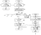
図1は、本発明の実施の形態によるリモートバーコードリーダシステムの全体構成を示す図である。図1を参照して、このリモートバーコードリーダシステムは、ホストコンピュータ(「センタサーバ」と呼ぶこともある。)7及び複数のバーコードリーダ1(図1では、1つのバーコードリーダ1のみを記載)を備える。なお、これらのバーコードリーダ1は、本システム専用である。 FIG. 1 is a diagram showing an overall configuration of a remote barcode reader system according to an embodiment of the present invention. Referring to FIG. 1, this remote barcode reader system includes a host computer (sometimes referred to as a “center server”) 7 and a plurality of barcode readers 1 (in FIG. 1, only one barcode reader 1 is used). Description). These bar code readers 1 are dedicated to this system.
ここで、バーコードとは、バーコード情報及びバーコードパターンを包括した表現であって、これらを厳密に区別する必要のないときは、単にバーコードなる用語を使用する。別の観点から、バーコードとは、物(物品・不動産などの有体物、情報(映像、音声、プログラム、データを含む。)・サービスなどの無体物、商品、人・動物などの生物を含む。)、その他の何らかの手段により識別可能なものに割り当てられたコードのことである。 Here, the bar code is a comprehensive expression of bar code information and a bar code pattern, and when it is not necessary to strictly distinguish these, the term bar code is simply used. From another point of view, the barcode includes intangibles such as objects (tangibles such as goods and real estate, information (including video, audio, programs, and data) and services), living things such as goods, people and animals. ), A code assigned to something that can be identified by some other means.
バーコード情報とは、数字、文字、及び記号等のキャラクタ列を意味する。バーコードパターンとは、バーコード情報を黒色バーと白色スペースとの組み合わせにより表現したパターンを意味する。なお、バーコード、バーコード情報、及びバーコードパターンには、同じ参照符合「13」を付する。 Bar code information means character strings such as numbers, letters, and symbols. The barcode pattern means a pattern in which barcode information is expressed by a combination of a black bar and a white space. The same reference symbol “13” is attached to the barcode, barcode information, and barcode pattern.
さて、バーコードリーダ1は、バーコードパターン13をスキャンして、バーコードパターン13のデコード結果、つまり、バーコード情報13と、当該バーコードリーダ1に固有に割り当てられた識別情報(以下、「ペンID」と呼ぶ。)と、を端末3に送信する。
The barcode reader 1 scans the
端末3は、バーコードリーダ1から受信したペンID及びバーコード情報13を、ネットワーク(例えば、インターネット、LAN等)5を介して、ホストコンピュータ7に送信する。
The
ホストコンピュータ7は、所定のアルゴリズムに従って、受信したペンIDをデコードし、当該ペンIDに適合するCGI(Common Gateway Interface)9−m(mは整数)を選択する。なお、図中、「M」は、CGIの総数から1を減算した値である。そして、ホストコンピュータ7は、選択したCGI9−mに、受信したバーコード情報13を送信する。なお、CGI9−mは、ネットワーク9上に配置することもできるし、ホストコンピュータ7に配置することもできる。
The
バーコード情報13を受け取ったCGI9−mは、そのバーコード情報13に応じた情報処理を実行する。この場合の具体的な処理は、CGI9−mの運営事業者等が任意かつ自由に企画設計するものであり、本リモートバーコードリーダシステムの関与するところではない。
The CGI 9-m that has received the
次に、図1のバーコードリーダ1について具体例を挙げながら詳細に説明する。 Next, the barcode reader 1 of FIG. 1 will be described in detail with specific examples.
図2(a)は、図1のバーコードリーダ1の一例を示す外観斜視図である。図2(b)は、図2(a)のバーコードリーダ1の電気的構成を示す図である。図2(c)は、図2(b)のMCU23に内蔵されたROM27に格納されたプログラム及びデータの概念図である。
FIG. 2A is an external perspective view showing an example of the barcode reader 1 of FIG. FIG. 2B is a diagram showing an electrical configuration of the barcode reader 1 shown in FIG. FIG. 2C is a conceptual diagram of programs and data stored in the
図2(a)を参照して、このバーコードリーダ1は、ペン型のバーコードリーダである。図2(b)を参照して、バーコードリーダ1は、スキャナ21、MCU23及び通信装置25を有する。スキャナ21は、バーコードパターン13を光学的に読み込み、バーとスペースを電気信号に変換する(スキャン)。スキャナ21からの、バーコードパターン13に応じた電気信号は、MCU23に与えられる。
Referring to FIG. 2A, the barcode reader 1 is a pen-type barcode reader. With reference to FIG. 2B, the barcode reader 1 includes a
MCU23は、CPU(図示せず)、RAM(図示せず)、A/Dコンバータ、及び図2(c)に示すROM27等を内蔵している。ROM27には、制御プログラム33、キーボードデータ形式のホストコンピュータ7のアドレス(ホストアドレスと呼ぶこともある。)35、キーボードデータ形式の端末3へのコマンド37、キーボードデータ形式の識別情報(ペンID)39、並びにその他必要なプログラム及びデータが格納される。なお、例えば、アドレス35は、ホストコンピュータ7のURL(Uniform Resource Locator)である。
The
コマンド37は、端末3に対して、ブラウザを起動し、アドレス35が示すホストコンピュータ7へアクセスすることを指示するコマンドである。例えば、OS(Operating System)がWindows(登録商標)の場合、Windows98以降において、コマンド37は、キーボードのGUI(Graphical User Interface)キー+Rキーに相当するキーボードデータである。このコマンド37により、Windowsでは、ブラウザ(Internet Explorer)が起動する。つまり、このコマンド37は、OSであるWindowsにおいて予め用意されているものである。なお、WindowsのGUIキーは、通称、Windowsキーと呼ばれるものである。Windowsのようにシェアが大きいOSに対するコマンド37をバーコードリーダ1に格納し出力するので、簡易に、つまり、バーコードリーダ1を端末3に接続するだけで、大部分の端末3を本システムのために利用できる。このため、バーコードリーダ1は、複数のコマンドを予め格納し、端末3ごとにOSを認識して、そのOSに応じたコマンドを選択して使用するといった処理が不要になる。
The
ペンID39は、バーコードリーダ1を識別するために割り当てられたユニークなコードである。
The
MCU23は、制御プログラム33を実行する。それによって、MCU23は、バーコードパターン13に応じた電気信号を解読して、バーコード情報13を取得する。そして、MCU23は、キーボードデータ形式に変換したバーコード情報13、並びに、ROM27に格納されたキーボードデータ形式のコマンド37、ホストアドレス35、及びペンID39を、通信装置25に与える。
The
通信装置25は、例えば、USBコントローラ等であり、MCU23から受け取ったキーボードデータ形式の出力用データ(コマンド37、ホストアドレス35、バーコード情報13、及びペンID39)を端末3に送信する。すると、端末3は、受信したコマンド37に応答して、受信したホストアドレス35に基づき、受信したバーコード情報13及びペンID39をネットワーク5を介してホストコンピュータ7へ送信する。
The
図3は、図2(b)のMCU23が行う処理の流れの一例を示すフローチャートである。図3を参照して、ステップS51にて、バーコードリーダ1のMCU23は、ユーザの操作に応答して、バーコードパターン13をスキャンする。ステップS53にて、MCU23は、周知のバーコード解読手法に基づいて、バーコードパターン13を解読し、バーコード情報13を取得する。ステップS55にて、MCU23は、バーコード情報13(例えば、「4560256580016」)、ホストアドレス35(例えば、「www.ssd.co.jp」)、及びペンID39(例えば、「15555」)から、出力用データ(例えば、「www.ssd.co.jp/?bc=4560256580016&sn=15555」)を作成する。
FIG. 3 is a flowchart showing an example of the flow of processing performed by the
ステップS57にて、MCU23は、現在のモードを確認し、第1モードであればステップS59に進み、第2モードであればステップS63に進む。第1モードは、端末3に本システムのためのミドルウェアがインストールされていない場合、又は、インストールされていても起動していない場合のモードである。第2モードは、端末3に本システムのためのミドルウェアがインストールされ起動している場合のモードである。
In step S57, the
なお、バーコードリーダ1のデフォルトのモードは、第1モードである。後述のように、端末3でミドルウェアが起動している場合に、そのミドルウェアによって、第2モードに切り替えられる。
Note that the default mode of the barcode reader 1 is the first mode. As described later, when middleware is activated in the
さて、第1モードでは、ステップS59にて、MCU23は、ステップS55で作成した出力用データにコマンド37を付加する。そして、ステップS61にて、MCU23は、コマンド37を付加した出力用データを、キーボードデータとして、第1インタフェースから端末3へ送信する。第1インタフェースは、第1モードのときの端末3とのインタフェースである。
In the first mode, in step S59, the
一方、第2モードでは、ステップS63にて、MCU23は、ステップS55で作成した出力用データを、キーボードデータとして、第2インタフェースから端末3へ送信する。第2インタフェースは、第2モードのときの端末3とのインタフェースである。
On the other hand, in the second mode, in step S63, the
次に、バーコードリーダ1から出力用データを受信した端末3での処理を説明する。
Next, processing in the
図4(a)は、図3のステップS61からデータを受信した端末3による処理の流れの一例を示すフローチャートである。図4(a)を参照して、図3のステップS61でMCU23が出力用データを送信すると、ステップS81にて、端末3の汎用キーボードドライバは、その出力用データをバーコードリーダ1の第1モードのインタフェースから受信する。そして、ステップS83にて、端末3のOSは、受信した出力用データに含まれるコマンド37によって、受信した出力用データに含まれるホストアドレス35、ペンID39及びバーコード13を引数として、端末3のブラウザを起動する。すると、ステップS85にて、起動したブラウザは、受け取ったホストアドレス35に基づき、ホストコンピュータ7にアクセスして、ペンID39及びバーコード13をホストコンピュータ7に送信する。
FIG. 4A is a flowchart illustrating an example of the flow of processing by the
さて、図4(b)は、図3のステップS63からデータを受信した端末3による処理の流れの一例を示すフローチャートである。なお、ミドルウェアは起動しているものとする。図4(b)を参照して、図3のステップS63でMCU23が出力用データを送信すると、ステップS91にて、端末3のHID(Human Interface Device)準拠ドライバは、その出力用データをバーコードリーダ1の第2モードのインタフェースから受信する。そして、ステップS93にて、端末3のミドルウェアは、HID準拠ドライバから出力用データを受信する。ステップS95にて、ミドルウェアは、受信した出力用データに含まれるホストアドレス35、ペンID39及びバーコード13を引数として、端末3のブラウザを起動する。すると、ステップS97にて、起動したブラウザは、受け取ったホストアドレス35に基づき、ホストコンピュータ7にアクセスして、ペンID39及びバーコード13をホストコンピュータ7に送信する。
FIG. 4B is a flowchart showing an example of the flow of processing by the
なお、上記例において、バーコードリーダ1が送信するホストアドレス35には、プロトコル「http://」が付加されていないので、図4(a)及び図4(b)の処理では、端末3のブラウザが、これをホストアドレス35に付加する。また、図4(a)及び図4(b)において、ブラウザが既に起動している場合は、起動は行われない。
In the above example, since the protocol “http: //” is not added to the
次に、端末3にインストールされたミドルウェアの処理をもう少し詳しく説明する。
Next, middleware processing installed in the
図5は、ミドルウェアによる処理の流れの一例を示すフローチャートである。なお、ミドルウェアが既に起動しているものとする。図5を参照して、端末3が起動すると、ステップS121にて、ミドルウェアは、HID準拠ドライバがバーコードリーダ1を検出したか否かを確認し、検出していない場合ステップS121に戻り、検出した場合ステップS123に進む。 FIG. 5 is a flowchart illustrating an example of the flow of processing by the middleware. It is assumed that the middleware has already started. Referring to FIG. 5, when terminal 3 is activated, in step S121, the middleware checks whether or not the HID-compliant driver has detected bar code reader 1, and if not detected, returns to step S121 to detect If so, the process proceeds to step S123.
ステップS123にて、ミドルウェアは、HID準拠ドライバを介して、バーコードリーダ1のモードを第2モードに切り替える。なお、バーコードリーダ1のデフォルトのモードは、第1モードである。ステップS125にて、ミドルウェアは、HID準拠ドライバがバーコードリーダ1の第2モードのインタフェースからデータを受信したか否か確認し、受信していない場合ステップS125に戻り、受信した場合ステップS127に進む。ステップS127にて、ミドルウェアは、HID準拠ドライバから、受信データを受け取る。そして、ステップS129にて、受信データに含まれるホストアドレス35、ペンID39、及びバーコード13を引数として、ブラウザを起動する。そして、図4(b)のステップS97の処理が実行される。
In step S123, the middleware switches the mode of the barcode reader 1 to the second mode via the HID-compliant driver. Note that the default mode of the barcode reader 1 is the first mode. In step S125, the middleware confirms whether or not the HID-compliant driver has received data from the second mode interface of the barcode reader 1. If not, the middleware returns to step S125, and if received, proceeds to step S127. . In step S127, the middleware receives received data from the HID-compliant driver. In step S129, the browser is activated with the
なお、ステップS123で第2モードに切り替えられた後は、第2モードが保持され、電源オフや再起動されない限り、それ以降、ステップS121及びS123の処理は実行されない。ただし、ミドルウェアは、それが終了する場合、HID準拠ドライバを介して、バーコードリーダ1を第1モードに設定する。そして、ミドルウェアが再び起動されると、図5の処理が実行される。 In addition, after switching to the 2nd mode by step S123, the 2nd mode is hold | maintained and the process of step S121 and S123 is not performed after that unless the power supply is turned off and it restarts. However, when the middleware ends, the middleware sets the barcode reader 1 to the first mode via the HID-compliant driver. Then, when the middleware is activated again, the process of FIG. 5 is executed.
次に、図1のホストコンピュータ7について具体例を挙げながら詳細に説明する。
Next, the
図6(a)は、図1のホストコンピュータ7の電気的構成を示す図である。図6(b)は、図1のホストコンピュータ7の記憶領域81の構成を示す概念図である。
FIG. 6A is a diagram showing an electrical configuration of the
図6(a)を参照して、ホストコンピュータ7は、CPU(中央演算処理装置)51、メインメモリ53、チップセット55、GPU(グラフィックスプロセシングユニット)57、SPU(サウンドプロセシングユニット)59、HDD(ハードディスクドライブ)61、ドライブ63、及び通信部65を含む。
Referring to FIG. 6A, the
CPU51は、HDD61に格納されたコンピュータプログラムを実行して各種演算を行う。メインメモリ53は、CPU51から直接読み書きが行われる高速のメモリである。GPU57は、グラフィックス処理を実行し、モニタ67に映像信号を与える。SPU59は、サウンド処理を実行し、スピーカ69に音声信号を与える。HDD61は、OSやアプリケーションソフトウェア等のコンピュータプログラム並びにこれらが用いるデータを書き込むために用いる補助記憶装置である。ドライブ63は、リムーバル記録媒体75からデータを読み込んだり、書き込んだりする装置である。通信部65は、ネットワーク9への接続を司るLANカードやUSBコントローラなどを含み(図示せず)、通信を制御する。
The
CPU51、GPU57、SPU59、HDD61、ドライブ63、通信部65、キーボード71、及びマウス73といった機能ユニットは、チップセット55に接続される。チップセット55は、これに接続される機能ユニット間のデータの受け渡しを管理する。
Functional units such as the
なお、図1の端末3の電気的構成は、図4(a)のホストコンピュータ7の電気的構成と同様であり、説明を省略する。
The electrical configuration of the
さて、図6(b)を参照して、ホストコンピュータ7のHDD61の記憶領域81は、プログラム格納部83及びデータベース11を備えている。
Now, referring to FIG. 6B, the
データベース11は、ペンIDとCGIとを関連付けたものであり、ペンIDから、それに関連付けられたCGIを読み出すことができる。例えば、各バーコードリーダ1に割り当てるCGI9−mを予め決めて、データベース11を作成し、それから、バーコードリーダ1を配布ないしは販売する。また、例えば、初回のアクセス時に、ユーザが、端末3を介して、ホストコンピュータ7が提供する所定のWEBサイトから、所望のCGI9−mを選択し、それから、端末3からのペンIDとユーザが選択したCGI9−mとをデータベース11に登録する。
The
プログラム格納部83は、通信制御部85、第1デコーダ87、及び第2デコーダ89−0,…,89−m,…,89−Mを含む。第2デコーダ89−0,…,89−m,…,89−Mは、それぞれ、CGI9−0,…,9−m,…,9−Mに対応して起動される。
The
これらの各機能部は、HDD61にインストールされたコンピュータソフトウエアプログラム若しくは1つのプログラム中のサブルーチンである。これらのプログラムは、リムーバル記録媒体75に格納され、これから、ホストコンピュータ7にインストールされる。これらの各機能部は、次のフローチャートを用いて説明される。
Each of these functional units is a computer software program installed in the
図7は、図1の端末3とホストコンピュータ7とCGI9−mとの間の通信手順の一例を示す図である。図7を参照して、ステップS1にて、端末3は、バーコードリーダ1から受け取ったペンID39及びバーコード13をホストコンピュータ7へ送信する(詳細は図4(a)及び図4(b)参照)。
FIG. 7 is a diagram illustrating an example of a communication procedure among the
すると、ステップS31にて、ホストコンピュータ7の通信制御部85は、バーコード13及びペンID39を受信する。そして、ステップS33にて、ホストコンピュータ7の第1デコーダ87は、第1所定アルゴリズム(本実施の形態ではペンID39に基づきデータベース11を検索するためのアルゴリズム)に従って、ペンID39をデコードして、バーコードリーダ1に適合するCGI9−mを選択する。即ち、第1デコーダ87は、受信したペンID39から、データベース11を検索し、当該ペンID39に関連付けられたCGI9−mの情報を取得する。
Then, in step S31, the
ステップS35にて、第1デコーダ87は、選択したCGI−mに対応する第2デコーダ89−mに、受信したバーコード13を渡す。すると、第2デコーダ89−mは、選択されたCGI9−mに対応する第2所定アルゴリズムに従って処理を実行する。
In step S35, the
例えば、選択したCGIがCGI9−0の場合、ステップS35にて、第1デコーダ87は、バーコード13を、第2デコーダ89−0に渡す。すると、ステップS37にて、第2デコーダ89−0は、受け取ったバーコード13をそのまま、通信制御部85を介して、選択されたCGI9−0に送信する。この場合、第2所定アルゴリズムは、バーコード13をそのままCGI9−0に送信するためのアルゴリズムである。
For example, if the selected CGI is CGI 9-0, the
すると、ステップS101−0にて、CGI9−0は、通信制御部85からバーコード13を受信する。そして、ステップS103−0にて、CGI9−0は、バーコード13に応じた処理を実行する。
Then, the CGI 9-0 receives the
また、例えば、選択したCGIがCGI9−1の場合、ステップS35にて、第1デコーダ87は、バーコード13を、第2デコーダ89−1に渡す。すると、ステップS39にて、第2デコーダ89−1は、CGI9−1に対応する第2所定アルゴリズムに従って、受け取ったバーコード13をデコードする。この場合、第2所定アルゴリズムは、対応するCGI9−1に応じて設計ないしは提供される。そして、ステップS41にて、第2デコーダ89−1は、バーコード13のデコード結果を、通信制御部85を介して、CGI9−1に送信する。
For example, when the selected CGI is CGI9-1, in step S35, the
すると、ステップS101−1にて、CGI9−1は、通信制御部85からバーコード13のデコード結果を受信する。そして、ステップS103−1にて、CGI9−1は、バーコード13のデコード結果に応じた処理を実行する。
In step S101-1, the CGI 9-1 receives the decoding result of the
なお、各CGI9−mの具体的な処理は、各CGI9−mの運営事業者等が任意かつ自由に企画設計するものであり、本リモートバーコードリーダシステムの関与するところではない。 The specific processing of each CGI 9-m is planned and designed arbitrarily and freely by the operator of each CGI 9-m, and is not involved in this remote barcode reader system.
さて、以上のように、本実施の形態によれば、ペンIDを、CGI9−mを選択するために利用して、バーコードリーダ1が読み込んだバーコード13及び/又はそのデコード結果を、適切なCGI9−mに与えることができる。その結果、バーコードリーダ1に応じた適切なCGI9−mが起動され、当該CGI9−mは、受け取ったバーコード13及び/又はそのデコード結果に応じた情報処理を実行できる。
As described above, according to the present embodiment, the pen ID is used to select the CGI 9-m, and the
(第1変形例) (First modification)
上記実施の形態では、端末3にミドルウェアをインストールする例を示した。これに対して、本実施の形態の第1変形例では、上記ミドルウェアをインストールせずに、第1変形例におけるリモートコードリーダシステムのためのプラグインを端末3のブラウザに付加する。つまり、上記実施の形態と第1変形例とは、バーコードリーダ1とブラウザとの間を仲介するプログラムが異なる。その他の点は、上記実施の形態と同様である。従って、図1及び図7は、第1変形例にも同様に適用できる。また、第1変形例の端末3やホストコンピュータ7のハードウェア構成は、図6(a)及び図6(b)と同じである。第1変形例のバーコードリーダ1のハードウェア構成は、図2(a)及び図2(b)と同じである。以下、異なる点を中心に説明する。なお、このプラグインは、CD−ROM等のリムーバル記録媒体やネットワーク5上のサーバ等から提供することができる。
In the above embodiment, an example in which middleware is installed in the
第1変形例のバーコードリーダ1の処理は、図3の処理と同様である。ただし、第1変形例では、バーコードリーダ1の第1モードは、端末3のブラウザに本システムのためのプラグインが付加されていない場合、プラグインが付加されているブラウザが起動していない場合、又は、プラグインが付加されているブラウザが起動しているがインアクティブ(バックグラウンド)の場合のモードである。また、第2モードは、端末3のブラウザに本システムのためのプラグインが付加されており、かつ、ブラウザが起動していて、かつ、ブラウザがアクティブ(フォアグラウンド)な場合のモードである。
The processing of the barcode reader 1 of the first modification is the same as the processing of FIG. However, in the first modification, in the first mode of the barcode reader 1, when the plug-in for this system is not added to the browser of the
また、第1変形例のバーコードリーダ1が第1モードの場合の端末3の処理は、図4(a)の処理と同じである。
Further, the process of the
次に、第1変形例のバーコードリーダ1が第2モードの場合の端末3の処理を説明する。
Next, processing of the
図8(a)は、本発明の実施の形態の第1変形例における第2モードでの端末3による処理の流れの一例を示すフローチャートである。図8(a)を参照して、図3のステップS63でMCU23が出力用データを送信すると、ステップS141にて、端末3のHID準拠ドライバは、その出力用データをバーコードリーダ1の第2モードのインタフェースから受信する。そして、ステップS143にて、端末3のブラウザに付加されたプラグインは、HID準拠ドライバから出力用データを受信する。
FIG. 8A is a flowchart showing an example of the flow of processing by the
そして、ステップS145にて、プラグインは、受信した出力用データに含まれるホストアドレス35、ペンID39及びバーコード13を引数として、ブラウザを制御する。
In step S145, the plug-in controls the browser using the
例えば、プラグインは、ブラウザに対して、ホストアドレス35が示すホストコンピュータ7にアクセスさせ、ペンID39及びバーコード13をホストコンピュータ7に送信させる。その後のホストコンピュータ7及びCGI9−mの処理は、図7に示したものと同様である。
For example, the plug-in causes the browser to access the
また、例えば、プラグインは、ブラウザに対して、ペンID39及び/又はバーコード13を渡し、ブラウザに、ペンID39及び/又はバーコード13を用いた処理をローカル(端末3)で実行させる。この場合、例えば、ブラウザは、それ自身の機能、Java(登録商標)Script等のスクリプト、Java(登録商標)アプレット、あるいは、Flash(登録商標)プレイヤ等のプラグインを実行して、ペンID39及び/又はバーコード13に応じた処理を実行する。
For example, the plug-in passes the
次に、ブラウザに付加されたプラグインの処理をもう少し詳しく説明する。 Next, the plug-in processing added to the browser will be described in a little more detail.
図8(b)は、第1変形例における第2モードでのプラグインよる処理の流れの一例を示すフローチャートである。なお、ブラウザはインアクティブな状態であるとする。図8(b)を参照して、ステップS161にて、プラグインは、HID準拠ドライバがバーコードリーダ1を検出したか否かを確認し、検出していない場合ステップS161に戻り、検出した場合ステップS163に進む。 FIG. 8B is a flowchart showing an example of the processing flow by the plug-in in the second mode in the first modification. It is assumed that the browser is in an inactive state. Referring to FIG. 8B, in step S161, the plug-in confirms whether or not the HID-compliant driver has detected the barcode reader 1, and if not detected, returns to step S161, and if detected. The process proceeds to step S163.
ステップS163にて、プラグインは、HID準拠ドライバを介して、バーコードリーダ1のモードを第2モードに切り替える。なお、バーコードリーダ1のデフォルトのモードは、第1モードである。ステップS165にて、プラグインは、HID準拠ドライバがバーコードリーダ1の第2モードのインタフェースからデータを受信したか否か確認し、受信していない場合ステップS165に戻り、受信した場合ステップS167に進む。ステップS167にて、プラグインは、HID準拠ドライバから、受信データを受け取る。そして、ステップS169にて、プラグインは、受信データに含まれるホストアドレス35、ペンID39、及びバーコード13を引数として、ブラウザを制御する。
In step S163, the plug-in switches the mode of the barcode reader 1 to the second mode via the HID-compliant driver. Note that the default mode of the barcode reader 1 is the first mode. In step S165, the plug-in checks whether or not the HID-compliant driver has received data from the second mode interface of the barcode reader 1, and returns to step S165 if not received and returns to step S167 if received. move on. In step S167, the plug-in receives received data from the HID-compliant driver. In step S169, the plug-in controls the browser using the
なお、ステップS163で第2モードに切り替えられた後は、第2モードが保持され、電源オフや再起動されない限り、それ以降、ステップS161及びS163の処理は実行されない。ただし、プラグインは、ブラウザが終了した場合、又は、インアクティブになった場合、HID準拠ドライバを介して、バーコードリーダ1を第1モードに設定する。そして、ブラウザが再びアクティブになると、図8(b)の処理が実行される。 Note that after switching to the second mode in step S163, the processing in steps S161 and S163 is not executed thereafter unless the second mode is maintained and the power is turned off or restarted. However, the plug-in sets the barcode reader 1 to the first mode via the HID-compliant driver when the browser is terminated or becomes inactive. Then, when the browser becomes active again, the process of FIG. 8B is executed.
以上により、第1変形例は、上記実施の形態と同様の効果を奏する。 As described above, the first modified example has the same effect as the above embodiment.
(第2変形例) (Second modification)
本実施の形態の第2変形例では、端末3に上記ミドルウェアがインストールされ、かつ、端末3のブラウザに上記プラグインが付加される。従って、バーコードリーダ1からのデータ取得に競合が発生する場合があり、いずれか一方を有効にする。第2変形例では、そのための制御が要求される。その他の点は、上記実施の形態と同様である。従って、図1及び図7は、第2変形例にも同様に適用できる。また、第2変形例の端末3やホストコンピュータ7のハードウェア構成は、図6(a)及び図6(b)と同じである。第2変形例のバーコードリーダ1のハードウェア構成は、図2(a)及び図2(b)と同じである。以下、異なる点を中心に説明する。
In the second modification of the present embodiment, the middleware is installed in the
第2変形例のバーコードリーダ1の処理は、図3の処理と同様である。ただし、第2変形例では、バーコードリーダ1の第1モード及び第2モードは次のようになる。モードの説明の前に、いくつかの状態を定義する。第1状態は、端末3のブラウザに本システムのためのミドルウェアがインストールされていない状態である。第2状態は、端末3にミドルウェアがインストールされているが起動していない状態である。第3状態は、ブラウザにプラグインが付加されていない状態である。第4状態は、プラグインが付加されているブラウザが起動していない状態である。
The process of the barcode reader 1 of the second modification is the same as the process of FIG. However, in the second modification, the first mode and the second mode of the barcode reader 1 are as follows. Before describing the mode, several states are defined. The first state is a state in which the middleware for this system is not installed in the browser of the
このように定義した場合、第1モードは、第1状態かつ第3状態の場合、第1状態かつ第4状態の場合、第2状態かつ第3状態の場合、又は、第2状態かつ第4状態の場合である。 When defined in this way, the first mode is the first state and the third state, the first state and the fourth state, the second state and the third state, or the second state and the fourth state. This is the case.
また、第2モードは、端末3にミドルウェアがインストールされて起動している場合、又は、プラグインが付加されているブラウザが起動していて、かつ、ブラウザがアクティブな場合のモードである。
The second mode is a mode in which middleware is installed and activated in the
また、第2変形例のバーコードリーダ1が第1モードの場合の端末3の処理は、図4(a)の処理と同じである。
Further, the process of the
次に、第2変形例のバーコードリーダ1が第2モードの場合の端末3の処理を説明する。この場合、端末3のミドルウェア及びプラグインのいずれか一方が有効になる(詳細は後述)。従って、ミドルウェアが有効な場合は、第2モードの端末3の処理は、図4(b)及び図5と同じである。一方、プラグインが有効な場合は、第2モードの端末3の処理は、図8(a)及び図8(b)と同じである。
Next, processing of the
次に、第2モードにおいて、ミドルウェアとプラグインとが競合する場合の制御について説明する。 Next, control when middleware competes with a plug-in in the second mode will be described.
図9は、本発明の実施の形態の第2変形例におけるバーコードリーダ1からのデータ取得に競合が発生する場合の制御の説明図である。なお、ミドルウェアは起動しているものとする。図9を参照して、ある時刻t0になる前では、ブラウザは起動していないか、あるいは、起動していてもインアクティブ(バックグラウンド)であるとする。この場合は、第2モードにおいて、ミドルウェアがアクティブ(有効)になり、上記処理を実行する。 FIG. 9 is an explanatory diagram of the control when a conflict occurs in data acquisition from the barcode reader 1 in the second modification of the embodiment of the present invention. Note that the middleware is activated. Referring to FIG. 9, it is assumed that the browser is not activated before reaching a certain time t0, or is inactive (background) even if activated. In this case, in the second mode, the middleware becomes active (valid), and the above processing is executed.
そして、時刻t0において、ブラウザが起動し、かつ、アクティブ(フォアグラウンド)になったとする。この場合、ブラウザに付加されたプラグインもアクティブ(有効)になり、上記処理を実行する。ただし、この時点では、ミドルウェアも有効であり、競合を排除する必要がる。このため、プラグインは、アクティブになると、ミューテックス(Mutex)機構により、ミドルウェアをロックする。これにより、ミドルウェアはインアクティブになる。 It is assumed that the browser is activated and becomes active (foreground) at time t0. In this case, the plug-in added to the browser is also activated (valid), and the above processing is executed. However, middleware is also effective at this point, and it is necessary to eliminate competition. Therefore, when the plug-in becomes active, the middleware is locked by the mutex mechanism. As a result, the middleware becomes inactive.
さらに、時刻t1において、ブラウザが起動しているがインアクティブになると、プラグインは、ミューテックス機構により、ミドルウェアをアンロック(解除)して、自らはインアクティブになる。これにより、ミドルウェアは、アクティブになり上記処理を実行する。 Further, at time t1, when the browser is activated but becomes inactive, the plug-in unlocks (releases) the middleware by the mutex mechanism and becomes inactive. As a result, the middleware becomes active and executes the above processing.
そして、さらに、時刻t2において、ブラウザが終了すると、プラグインも同時に終了する。ただし、ミドルウェアはアンロックされたままであるので、ブラウザが起動され、かつ、アクティブになるまで、ミドルウェアは引き続き、上記処理を実行する。 Further, when the browser is terminated at time t2, the plug-in is also terminated at the same time. However, since the middleware remains unlocked, the middleware continues to execute the above process until the browser is activated and activated.
なお、ミューテックスは、相互排他(Mutual Exclusion)のことである。 Note that mutex refers to mutual exclusion.
ところで、プラグインが付加されたブラウザがインアクティブ若しくは終了する際に(例えば時刻t0、t1)、ミドルウェアが起動していない場合は、プラグインは、HID準拠ドライバを介して、バーコードリーダ1を第1モードに設定する。一方、ミドルウェアが終了する際に、プラグインが付加されたブラウザがインアクティブ若しくは起動していない場合、ミドルウェアは、HID準拠ドライバを介して、バーコードリーダ1を第1モードに設定する。 By the way, when the middleware is not activated when the browser to which the plug-in is added is inactive or terminated (for example, times t0 and t1), the plug-in uses the barcode reader 1 via the HID-compliant driver. Set to the first mode. On the other hand, if the browser to which the plug-in is added is not inactive or activated when the middleware is terminated, the middleware sets the barcode reader 1 to the first mode via the HID-compliant driver.
以上により、第2変形例は、上記実施の形態と同様の効果を奏する。 As described above, the second modified example has the same effect as the above embodiment.
(第3変形例) (Third Modification)
図1を参照して、実施の形態の第3変形例の概要を説明する。バーコードリーダ1は、バーコードパターン13をスキャンして、バーコード情報13及びペンID(任意)を端末3に送信する。端末3は、当該端末3を識別するための情報(以下、「端末ID」と呼ぶ。)、並びに、バーコードリーダ1から受信したペンID(任意)及びバーコード情報13を、ネットワーク5を介して、ホストコンピュータ7に送信する。なお、端末IDは、ホストコンピュータ7が端末3を識別するための情報である。
With reference to FIG. 1, the outline of the third modification of the embodiment will be described. The barcode reader 1 scans the
ホストコンピュータ7は、所定のアルゴリズムに従って、受信した端末IDをデコードし、当該端末IDに適合するCGI9−mを選択する。そして、ホストコンピュータ7は、選択したCGI9−mに、受信したバーコード情報13を送信する。
The
バーコード情報13を受け取ったCGI9−mは、そのバーコード情報13に応じた情報処理を実行する。この場合の具体的な処理は、CGI9−mの運営事業者等が任意かつ自由に企画設計するものであり、本リモートバーコードリーダシステムの関与するところではない。
The CGI 9-m that has received the
以下、上記実施の形態と異なる点を中心に詳細に説明していく。 Hereinafter, the difference from the above embodiment will be described in detail.
第3変形例のバーコードリーダ1は、上記実施の形態の第1モードを有しておらず、第2モードに固定され、かつ、端末3には上記ミドルウェアがインストールされているものとする。
It is assumed that the barcode reader 1 of the third modification does not have the first mode of the above embodiment, is fixed in the second mode, and the middleware is installed in the
また、第3変形例の端末3のハードウェア構成は、図6(a)と同じである。また、第3変形例のバーコードリーダ1のハードウェア構成は、図2(a)と同じである。ただし、ROM27に、コマンド37は格納されない。また、ペンID39は、ROM27に格納されてもよいし、格納されなくてもよく、任意である。
The hardware configuration of the
第3変形例のバーコードリーダ1の処理は、図3の処理と同様である。ただし、バーコードリーダ1は第2モードのみを搭載するので、ステップS57,S59及びS61は実行されず、ステップS55の後は、ステップS63が実行される。 The process of the barcode reader 1 of the third modification is the same as the process of FIG. However, since the barcode reader 1 is equipped with only the second mode, steps S57, S59 and S61 are not executed, and step S63 is executed after step S55.
次に、第3変形例の端末3の処理を説明する。
Next, the process of the
図10は、本発明の実施の形態の第3変形例における端末3による処理の流れの一例を示すフローチャートである。図10を参照して、ステップS201及びステップS203の処理は、それぞれ、図4(b)のステップS91及びS93の処理と同様であり、説明を省略する。さて、ステップS205にて、ミドルウェアは、端末IDを作成する。具体的には、ミドルウェアは、端末3を構成する所定の1のハードウェアの情報を端末IDとし、又は、端末3を構成する所定の複数のハードウェアの情報を収集して、それらを結合し、端末IDとする。
FIG. 10 is a flowchart showing an example of the flow of processing by the
例えば、ハードウェアの情報は、ディスプレイアダプタのプロダクトID及び/又はシリアル番号、SCSIアダプタのプロダクトID及び/又はシリアル番号、IDEアダプタ(IDEコントローラ)のプロダクトID及び/又はシリアル番号、LANアダプタのMACアドレス、メインメモリのサイズ、CPUのタイプ、CPUのシリアル番号、HDDのタイプ、HDDのシリアル番号、並びに、CD−ROM/CD−R/DVD−ROM等のタイプである。 For example, the hardware information includes the product ID and / or serial number of the display adapter, the product ID and / or serial number of the SCSI adapter, the product ID and / or serial number of the IDE adapter (IDE controller), and the MAC address of the LAN adapter. The main memory size, the CPU type, the CPU serial number, the HDD type, the HDD serial number, and the CD-ROM / CD-R / DVD-ROM type.
さて、ステップS207にて、ミドルウェアは、受信した出力用データに含まれるホストアドレス35、ペンID39(もし含まれるならば)及びバーコード13、並びに、端末IDを引数として、端末3のブラウザを起動する。すると、ステップS209にて、起動したブラウザは、受け取ったホストアドレス35に基づき、ホストコンピュータ7にアクセスして、ペンID39(もし含まれるならば)、バーコード13、及び端末IDをホストコンピュータ7に送信する。
In step S207, the middleware activates the browser of the
次に、ホストコンピュータ7の構成及び処理について説明する。第3変形例のホストコンピュータ7のハードウェア構成は、図6(a)及び図6(b)と同様である。ただし、データベース11は、端末IDとCGI9−mとを関連付けたものである。例えば、初回のアクセス時に、ユーザが、端末3を介して、ホストコンピュータ7が提供する所定のWEBサイトから、所望のCGI9−mを選択し、それから、端末3からの端末IDとユーザが選択したCGI9−mとをデータベース11に登録する。
Next, the configuration and processing of the
また、例えば、初回のアクセス時に、ユーザが、端末3を介して、ホストコンピュータ7が提供する所定のWEBサイトから、所望のCGI9−mを選択し、さらに、ホストコンピュータ7が、端末IDを作成し、それから、ホストコンピュータ7が作成した端末IDとユーザが選択したCGI9−mとをデータベース11に登録し、当該端末IDを端末3のミドルウェアに送信する。また、例えば、各ミドルウェアに割り当てるCGI9−mを予め決めて、ミドルウェアの識別情報とCGI9−mとを関連付けたデータベース11を作成し、それから、ミドルウェアを配布ないしは販売する。この場合、ミドルウェアの識別情報が、端末IDとして使用される。なお、ミドルウェアの識別情報は、ネットワーク5を介して、ホストコンピュータ7から取得、または、ミドルウェアに予め持たせておく。また、下記第4変形例では、これらの例において、ミドルウェアをプラグインと読み替える。
Further, for example, at the first access, the user selects a desired CGI 9-m from a predetermined WEB site provided by the
第3変形例における端末3とホストコンピュータ7とCGI9−mとの間の通信手順は、図7の説明において、「ペンID39」を「端末ID」と読み替えることにより説明される。
The communication procedure among the
つまり、ステップS1にて、端末3は、バーコードリーダ1から受け取ったペンID39(任意)及びバーコード13、並びに、端末IDをホストコンピュータ7へ送信する。
That is, in step S 1, the
すると、ステップS31にて、ホストコンピュータ7の通信制御部85は、バーコード13及びペンID39(任意)並びに端末IDを受信する。そして、ステップS33にて、ホストコンピュータ7の第1デコーダ87は、第1所定アルゴリズム(本実施の形態では端末IDに基づきデータベース11を検索するためのアルゴリズム)に従って、端末IDをデコードして、バーコードリーダ1に適合するCGI9−mを選択する。即ち、第1デコーダ87は、受信した端末IDから、データベース11を検索し、当該端末IDに関連付けられたCGI9−mの情報を取得する。
Then, in step S31, the
ステップS35にて、第1デコーダ87は、選択したCGI−mに対応する第2デコーダ89−mに、受信したバーコード13を渡す。すると、第2デコーダ89−mは、選択されたCGI9−mに対応する第2所定アルゴリズムに従って処理を実行する。第3変形例の第2デコーダ89−mの処理及びCGI9−mの処理は、上記実施の形態と同じである。
In step S35, the
さて、以上のように、本実施の形態の第3変形例によれば、端末IDを、CGI9−mを選択するために利用して、バーコードリーダ1が読み込んだバーコード13及び/又はそのデコード結果を、適切なCGI9−mに与えることができる。その結果、端末3に応じた適切なCGI9−mが起動され、当該CGI9−mは、受け取ったバーコード13及び/又はそのデコード結果に応じた情報処理を実行できる。
As described above, according to the third modification of the present embodiment, the barcode ID 1 read by the barcode reader 1 and / or the barcode is read using the terminal ID to select the CGI 9-m. The decoding result can be given to an appropriate CGI 9-m. As a result, an appropriate CGI 9-m corresponding to the
(第4変形例) (Fourth modification)
本発明の実施の形態の第4変形例は、第3変形例のミドルウェアの処理をブラウザに付加されたプラグインが実行する。従って、第4変形例は、端末3での処理主体が第3変形例と異なる。以下、異なる点を中心に説明する。
In the fourth modification of the embodiment of the present invention, the middleware process of the third modification is executed by a plug-in added to the browser. Therefore, the fourth modified example is different from the third modified example in the processing subject in the
図11は、本発明の実施の形態の第4変形例における端末3による処理の流れの一例を示すフローチャートである。図11を参照して、ステップS221及びステップS223の処理は、それぞれ、図8(a)のステップS141及びS143の処理と同様であり、説明を省略する。さて、ステップS225にて、プラグインは、端末IDを作成する。作成方法は、図10のステップS205と同じである。ステップS227にて、プラグインは、受信した出力用データに含まれるホストアドレス35、ペンID39(もし含まれるならば)及びバーコード13、並びに、端末IDを引数として、端末3のブラウザを制御する。この場合のブラウザの制御の例は、図8(a)のステップS145で挙げたものと同じである。ただし、第4変形例では、ペンID39(任意)及びバーコード13に加えて、端末IDが利用される。なお、これらをホストコンピュータ7に送信する制御を行う場合、ホストコンピュータ7及びCGI9−mの処理は、第3変形例と同様である。
FIG. 11 is a flowchart showing an example of the flow of processing by the
以上により、第4変形例は、上記第3変形例と同様の効果を奏する。 As described above, the fourth modified example has the same effect as the third modified example.
(第5変形例) (5th modification)
本発明の実施の形態の第5変形例では、端末3に第3変形例のミドルウェアがインストールされ、端末3のブラウザに第4変形例のプラグインが付加されている。従って、第5変形例のミドルウェア及びプラグインの処理は、それぞれ、第3変形例のミドルウェア及び第4変形例のプラグインと同様である。
In the fifth modification of the embodiment of the present invention, the middleware of the third modification is installed in the
ただし、上記第2変形例と同様に競合の問題が発生するので、上記第2変形例と同じ手段で競合を回避する。 However, since a problem of contention occurs in the same way as in the second modified example, the conflict is avoided by the same means as in the second modified example.
以上により、第5変形例は、上記第3変形例と同様の効果を奏する。 As described above, the fifth modification has the same effect as the third modification.
(第6変形例) (Sixth Modification)
本発明の実施の形態の第6変形例は、上記第3変形例の端末IDの代わりに、ユーザを識別する情報(以下、「ユーザID」と呼ぶ。)を使用する。従って、第6変形例では、図10のステップS205にて、ミドルウェアは、ユーザIDをHDDから取得する。そして、ステップS207にて、ミドルウェアは、受信した出力用データに含まれるホストアドレス35、ペンID39(もし含まれるならば)及びバーコード13、並びに、ユーザIDを引数として、端末3のブラウザを起動する。すると、ステップS209にて、起動したブラウザは、受け取ったホストアドレス35に基づき、ホストコンピュータ7にアクセスして、ペンID39(もし含まれるならば)、バーコード13、及びユーザIDをホストコンピュータ7に送信する。
The sixth modification of the embodiment of the present invention uses information for identifying a user (hereinafter referred to as “user ID”) instead of the terminal ID of the third modification. Therefore, in the sixth modified example, the middleware acquires the user ID from the HDD in step S205 of FIG. In step S207, the middleware activates the browser of the
また、第6変形例では、図6(b)のデータベース11は、ユーザIDとCGI9−mとを関連付ける。例えば、初回のアクセス時に、ユーザが、端末3を介して、ホストコンピュータ7が提供する所定のWEBサイトから、所望のCGI9−mを選択し、それから、ユーザIDとユーザが選択したCGI9−mとをデータベース11に登録する。この場合、例えば、ユーザがユーザIDを端末3に入力してホストコンピュータ7に与えることもできるし、ホストコンピュータ7がユーザIDを作成することもできる。そして、ホストコンピュータ7が端末3のミドルウェア(下記第7変形例ではプラグイン)にユーザIDを与える。
Further, in the sixth modification, the
また、例えば、各ミドルウェアに割り当てるCGI9−mを予め決めて、ミドルウェアの識別情報とCGI9−mとを関連付けたデータベース11を作成し、それから、ミドルウェアを配布ないしは販売する。この場合、ミドルウェアの識別情報が、ユーザIDとして使用される。なお、ミドルウェアの識別情報は、ネットワーク5を介して、ホストコンピュータ7から取得、または、ミドルウェアに予め持たせておく。また、下記第7変形例では、この例において、ミドルウェアをプラグインと読み替える。
Further, for example, the CGI 9-m to be assigned to each middleware is determined in advance, the
さて、第6変形例における端末3とホストコンピュータ7とCGI9−mとの間の通信手順は、第3変形例における図7の説明において、「端末ID」を「ユーザID」と読み替える。
In the communication procedure among the
さて、以上のように、本実施の形態の第6変形例によれば、ユーザIDを、CGI9−mを選択するために利用して、バーコードリーダ1が読み込んだバーコード13及び/又はそのデコード結果を、適切なCGI9−mに与えることができる。その結果、ユーザIDに応じた適切なCGI9−mが起動され、当該CGI9−mは、受け取ったバーコード13及び/又はそのデコード結果に応じた情報処理を実行できる。
As described above, according to the sixth modification of the present embodiment, the
(第7変形例) (Seventh Modification)
本発明の実施の形態の第7変形例は、上記第4変形例の端末IDの代わりに、ユーザIDを使用する。従って、第7変形例では、図11のステップS225にて、プラグインは、ユーザIDをHDDから取得する。そして、ステップS227にて、プラグインは、受信した出力用データに含まれるホストアドレス35、ペンID39(もし含まれるならば)及びバーコード13、並びに、ユーザIDを引数として、端末3のブラウザを制御する。この場合のブラウザの制御の例は、図8(a)のステップS145で挙げたものと同じである。ただし、第7変形例では、ペンID39(任意)及びバーコード13に加えて、ユーザIDが利用される。なお、これらをホストコンピュータ7に送信する制御を行う場合、ホストコンピュータ7及びCGI9−mの処理は、第6変形例と同様である。また、ユーザIDの入力例は、第6変形例と同じである。
The seventh modification of the embodiment of the present invention uses a user ID instead of the terminal ID of the fourth modification. Therefore, in the seventh modification, in step S225 of FIG. 11, the plug-in acquires the user ID from the HDD. In step S227, the plug-in uses the
以上により、第7変形例は、上記第6変形例と同様の効果を奏する。 As described above, the seventh modification has the same effect as the sixth modification.
(第8変形例) (Eighth modification)
本発明の実施の形態の第8変形例は、上記第5変形例の端末IDの代わりに、ユーザIDを使用する。従って、第8変形例では、端末3に第6変形例のミドルウェアがインストールされ、端末3のブラウザに第7変形例のプラグインが付加されている。この場合、第8変形例のミドルウェア及びプラグインの処理は、それぞれ、第6変形例のミドルウェア及び第7変形例のプラグインと同様である。
The eighth modification of the embodiment of the present invention uses a user ID instead of the terminal ID of the fifth modification. Accordingly, in the eighth modification, the middleware of the sixth modification is installed in the
ただし、上記第2変形例と同様に競合の問題が発生するので、上記第2変形例と同じ手段で競合を回避する。 However, since a problem of contention occurs in the same way as in the second modified example, the conflict is avoided by the same means as in the second modified example.
以上により、第8変形例は、上記第6変形例と同様の効果を奏する。 As described above, the eighth modification has the same effect as the sixth modification.
さて、以上のように、本実施の形態及びその第1〜第8変形例によれば、クライアント(バーコードリーダ1、ユーザ、端末3、及び、端末3にインストールされたソフトウェアを総称)の識別情報(ペンID、ユーザID、端末ID、若しくは、端末3にインストールされたソフトウェア(ミドルウェア又はプラグイン)の識別情報)を、機能(例えば、ホストコンピュータ7にインストールされたCGI9−m、他のサーバ、あるいは、それにインストールされたCGI9−m)を選択するために利用して、バーコードリーダ1が読み込んだバーコード13及び/又はそのデコード結果を、適切な機能に与えることができる。その結果、クライアントに応じた適切な機能が起動され、当該機能は、受け取ったバーコード13及び/又はそのデコード結果に応じた情報処理を実行できる。
As described above, according to the present embodiment and the first to eighth modifications thereof, the identification of the client (the barcode reader 1, the user, the
なお、本発明は、上記の実施の形態に限られるものではなく、その要旨を逸脱しない範囲で種々の態様において実施することが可能であり、例えば、以下のような変形も可能である。 The present invention is not limited to the above-described embodiment, and can be implemented in various modes without departing from the gist thereof. For example, the following modifications are possible.
(1)上記第3〜第5変形例では、端末IDを利用し、上記第6〜第8変形例では、ユーザIDを利用したが、これらの変形例において、端末ID及びユーザID、端末ID及びペンID、ユーザID及びペンID、又は、端末ID、ユーザID、及びペンIDを利用して、CGI9−mを選択することもできる。端末ID及びユーザIDを利用する場合、データベース11では、端末ID及びユーザIDと、CGI9−mと、が関連付けられる。端末ID及びペンIDを利用する場合、データベース11では、端末ID及びペンIDと、CGI9−mと、が関連付けられる。ユーザID及びペンIDを利用する場合、データベース11では、ユーザID及びペンIDと、CGI9−mと、が関連付けられる。端末ID、ユーザID、及びペンIDを利用する場合、データベース11では、端末ID、ユーザID、及びペンIDと、CGI9−mと、が関連付けられる。
(1) Although the terminal ID is used in the third to fifth modifications, and the user ID is used in the sixth to eighth modifications, the terminal ID, the user ID, and the terminal ID are used in these modifications. Also, the CGI 9-m can be selected by using the pen ID, the user ID and the pen ID, or the terminal ID, the user ID, and the pen ID. When the terminal ID and the user ID are used, the
(2)上記実施の形態において、バーコードリーダ1が第1モードのみを有し、ドライバ及びミドルウェアをインストールしないことも可能である。また、上記実施の形態及び第1〜第8変形例において、バーコードリーダ1が第2モードのみを有していてもよい。この場合は、バーコードリーダ1は、コマンド37を格納する必要はない。
(2) In the above embodiment, it is possible that the barcode reader 1 has only the first mode and the driver and middleware are not installed. Moreover, in the said embodiment and the 1st-8th modification, the barcode reader 1 may have only 2nd mode. In this case, the barcode reader 1 does not need to store the
上記では、ホストアドレス35は、バーコードリーダ1から端末3に与えられた。ただし、端末3が、予めホストアドレス35を持っていてもよいし、ユーザが入力することもできる。この場合は、バーコードリーダ1は、ホストアドレス35を格納する必要はない。また、上記第3〜第8変形例では、ペンIDは任意である。従って、ペンIDを利用しない場合、バーコードリーダ1は、ペンIDを格納する必要はない。
In the above description, the
上記第3〜第8変形例において、バーコードリーダ1が第2モードのみを有し、端末3が予めホストアドレス35を持ち、ペンIDを利用しない場合は、本システムに専用のバーコードリーダ1は不要であり(もちろん使うことも可能)、一般的な汎用のバーコードリーダを使用することができる。例えば、本システム専用に設計及び製造されたものではない、一般的なPOS(Point Of Sale)システムのために設計及び製造されたバーコードリーダを使用できる。
In the third to eighth modifications, when the barcode reader 1 has only the second mode, the
(3)上記では、ドライバやミドルウェアがブラウザを制御して、ホストコンピュータ7へバーコード13等を送信した。ただし、上記ドライバやミドルウェアの機能に加えて、通信機能を有する専用のソフトウェアを端末3にインストールし、ブラウザを介さずに処理をすることもできる。
(3) In the above, the driver or middleware controls the browser and transmits the
(4)上記では、ホストコンピュータ7及びCGI9−mに送信する情報として、バーコード13を採用したが、これに限定されない。例えば、RFID(Radio Frequency Identification System)タグ等の電子タグ(ICタグ)を利用できる。ただし、この場合には、バーコードリーダ1に代えて、電子タグリーダ(ICタグリーダ)で電子タグに格納された情報(コード)を読み込む。電子タグリーダには、上記実施の形態、若しくは、上記第1〜第8変形例の、バーコードスキャン以外の機能を搭載する。この場合、ペンIDの代わりに、電子タグリーダの識別情報を使用する。
(4) In the above description, the
また、上記では、一次元コードである一次元バーコードを利用したが、二次元コードである二次元バーコードやQRコード等を利用することもできる。また、二次元コードとして、人間には見え難いドットパターンにより表されたコードを利用することもできる。 In the above description, a one-dimensional barcode that is a one-dimensional code is used. However, a two-dimensional barcode that is a two-dimensional code, a QR code, or the like may be used. Further, as the two-dimensional code, a code represented by a dot pattern that is difficult for humans to see can be used.
(5)バーコードリーダ1として、携帯電話機のカメラを利用したバーコード認識機能を利用することもできる。QRコードの認識についても同様である。この場合、携帯電話機には、上記実施の形態、若しくは、上記第1〜第8変形例の、端末3及びバーコードリーダ1の機能を搭載する。また、この場合、ペンIDの代わりに、携帯電話機の識別情報を使用する。
(5) As the barcode reader 1, a barcode recognition function using a camera of a mobile phone can be used. The same applies to QR code recognition. In this case, the mobile phone is equipped with the functions of the
(6)上記では、ホストコンピュータ7は、バーコード13又はそのデコード結果をCGI9−mに渡した。ただし、バーコード13及びそのデコード結果の双方を渡すこともできる。また、ホストコンピュータ7は、バーコード13、バーコード13のデコード結果、又は、バーコード13及びそのデコード結果と共に、ペンID、端末ID、若しくは、ユーザID、または、それらの二以上の組合せを、CGI9−mに渡すこともできる。
(6) In the above, the
(7)上記では、ホストコンピュータ7は、ペンID、端末ID、若しくは、ユーザID、または、それらの二以上の組合せに基づいて、CGI9−mを選択した。ただし、これらを使用せずに、ホストコンピュータ7は、バーコード13に基づいて、CGI9−mを選択して、選択したCGI9−mに、バーコード13及び/又はバーコード13のデコード結果(図7のステップS39)を渡すこともできる。
(7) In the above, the
このように、バーコードリーダ1が読み込んだバーコード13を、機能(例えば、ホストコンピュータ7にインストールされたCGI9−m、他のサーバ、あるいは、それにインストールされたCGI9−m)を選択するために利用して、当該バーコード13及び/又はそのデコード結果を、適切な機能に与えることができる。その結果、バーコード13に応じた適切な機能が起動され、当該機能は、受け取ったバーコード13及び/又はそのデコード結果に応じた情報処理を実行できる。
In this way, the
なお、ホストコンピュータ7は、ペンID、端末ID、ユーザID、若しくは、バーコード13、又は、それらの二以上の組合せに基づいて、CGI9−mを選択することもできる。また、ホストコンピュータ7は、図7のステップS39にて、ペンID、端末ID、ユーザID、若しくは、バーコード13、又は、それらの二以上の組合せをデコードして、結果をCGI9−mに送信することもできる。
The
(8)CGIはクライアントに動的なサービスを提供する機能の一例であり、これに限定されない。例えば、ASP(Active Server Pages)であってもよい。 (8) CGI is an example of a function that provides a dynamic service to a client, and is not limited to this. For example, ASP (Active Server Pages) may be used.
(9)ホストコンピュータ7は、物理的に1つのコンピュータで構成することもできるし、処理を複数のコンピュータに分散させて構成することもできる。もちろん、分散処理する場合の各コンピュータの設置場所は、同一国内でもよいし、複数国に分散して設置してもよい。なお、ホストコンピュータ7は、ハードウェア及びソフトウェアを含む概念として使用している。これらのことは、サーバについても同様である。
(9) The
(10)本明細書及び特許請求の範囲において、手段とは必ずしも物理的手段を意味するものではなく、各手段の機能が、ソフトウェアによって実現される場合も包含する。さらに、一つの手段の機能が、二つ以上の物理的手段により実現されても、若しくは、二つ以上の手段の機能が、一つの物理的手段により実現されてもよい。この点、サーバやコンピュータについても同様である。 (10) In the present specification and claims, the means does not necessarily mean a physical means, but includes the case where the function of each means is realized by software. Furthermore, the function of one means may be realized by two or more physical means, or the functions of two or more means may be realized by one physical means. This also applies to servers and computers.
本発明は、例えば、バーコード、QRコード、ICタグに格納されたコード、及び、ドットパターンで表されたコード等をネットワークを介して収集及び処理する分野に利用可能である。 The present invention can be used, for example, in the field of collecting and processing a barcode, a QR code, a code stored in an IC tag, a code represented by a dot pattern, and the like via a network.
1…バーコードリーダ、3…端末、5…ネットワーク、7…ホストコンピュータ(センタサーバ)、9−0〜9−M(9−m)…CGI、11…データベース、13…バーコード。 DESCRIPTION OF SYMBOLS 1 ... Bar code reader, 3 ... Terminal, 5 ... Network, 7 ... Host computer (center server), 9-0 to 9-M (9-m) ... CGI, 11 ... Database, 13 ... Bar code.
Claims (19)
ネットワークに接続されたサーバと、を備え、
前記コードリーダを含むクライアントに固有の識別情報、及び、前記コードリーダが読み込んだ前記コードは、前記ネットワークに接続された端末を介して、前記サーバに送信され、
前記サーバは、
受信した前記識別情報をデコードして、当該識別情報に適合する機能を選択するデコード手段と、
前記コード、又は、前記コード及び前記識別情報を、選択した前記機能に処理させるために、当該機能に与える提供手段と、を含む、リモートコードリーダシステム。 A code reader to read the code,
A server connected to the network,
Identification information unique to the client including the code reader, and the code read by the code reader are transmitted to the server via a terminal connected to the network,
The server
Decoding means for decoding the received identification information and selecting a function that conforms to the identification information;
A remote code reader system, comprising: a provision unit that provides the code or the code and the identification information to the selected function to cause the selected function to process the code.
ネットワークに接続されたサーバと、を備え、
前記コードリーダを含むクライアントに固有の識別情報、及び、前記コードリーダが読み込んだ前記コードは、前記ネットワークに接続された端末を介して、前記サーバに送信され、
前記サーバは、
第1所定アルゴリズムに従って、受信した前記識別情報をデコードして、当該識別情報に適合する機能を選択する第1デコード手段と、
第2所定アルゴリズムに従って、受信した前記コードをデコードする第2デコード手段と、
前記コード、前記識別情報、及び、前記第2デコード手段によるデコードの結果のうち、少なくともデコードの結果を、選択した前記機能に処理させるために、当該機能に与える提供手段と、を含む、リモートコードリーダシステム。 A code reader to read the code,
A server connected to the network,
Identification information unique to the client including the code reader, and the code read by the code reader are transmitted to the server via a terminal connected to the network,
The server
First decoding means for decoding the received identification information in accordance with a first predetermined algorithm and selecting a function suitable for the identification information;
Second decoding means for decoding the received code according to a second predetermined algorithm;
A remote code comprising: a providing means for providing the selected function with at least a decoding result among the code, the identification information, and a result of decoding by the second decoding means; Reader system.
ネットワークに接続されたサーバと、を備え、
前記コードリーダが読み込んだ前記コードは、前記ネットワークに接続された端末を介して、前記サーバに送信され、
前記サーバは、
受信した前記コードをデコードして、当該コードに適合する機能を選択するデコード手段と、
前記コードを、選択した前記機能に処理させるために、当該機能に与える提供手段と、を含む、リモートコードリーダシステム。 A code reader to read the code,
A server connected to the network,
The code read by the code reader is transmitted to the server via a terminal connected to the network,
The server
Decoding means for decoding the received code and selecting a function that conforms to the code;
A remote code reader system comprising: means for providing the code with the selected function so that the function is processed.
ネットワークに接続されたサーバと、を備え、
前記コードリーダが読み込んだ前記コードは、前記ネットワークに接続された端末を介して、前記サーバに送信され、
前記サーバは、
第1所定アルゴリズムに従って、前記コードをデコードして、当該コードに適合する機能を選択する第1デコード手段と、
第2所定アルゴリズムに従って、前記コードをデコードする第2デコード手段と、
前記コード、及び、前記第2デコード手段によるデコードの結果のうち、少なくともデコードの結果を、選択した前記機能に処理させるために、当該機能に与える提供手段と、を含む、リモートコードリーダシステム。 A code reader to read the code,
A server connected to the network,
The code read by the code reader is transmitted to the server via a terminal connected to the network,
The server
First decoding means for decoding the code in accordance with a first predetermined algorithm and selecting a function suitable for the code;
Second decoding means for decoding the code according to a second predetermined algorithm;
A remote code reader system, comprising: a means for providing the selected function with at least a result of decoding among the code and a result of decoding by the second decoding means, so as to process the selected function.
受信した前記識別情報をデコードして、当該識別情報に適合する機能を選択するステップと、
前記コード、又は、前記コード及び前記識別情報を、選択した前記機能に処理させるために、当該機能に与えるステップと、を含むコード収集処理方法。 Receiving identification information unique to a client including a code reader for reading a code, and the code read by the code reader via the code reader and a terminal connected to a network;
Decoding the received identification information and selecting a function conforming to the identification information;
Providing the function to the selected function to cause the selected function to process the code or the code and the identification information.
第1所定アルゴリズムに従って、受信した前記識別情報をデコードして、当該識別情報に適合する機能を選択するステップと、
第2所定アルゴリズムに従って、受信した前記コードをデコードするステップと、
前記コード、前記識別情報、及び、前記第2所定アルゴリズムによるデコードの結果のうち、少なくともデコードの結果を、選択した前記機能に処理させるために、当該機能に与えるステップと、を含むコード収集処理方法。 Receiving identification information unique to a client including a code reader for reading a code, and the code read by the code reader via the code reader and a terminal connected to a network;
Decoding the received identification information according to a first predetermined algorithm and selecting a function that matches the identification information;
Decoding the received code according to a second predetermined algorithm;
A code collection processing method including a step of giving at least the decoding result to the selected function among the code, the identification information, and the decoding result by the second predetermined algorithm. .
受信した前記コードをデコードして、当該コードに適合する機能を選択するステップと、
前記コードを、選択した前記機能に処理させるために、当該機能に与えるステップと、を含むコード収集処理方法。 Receiving the code read by the code reader that reads the code via the code reader and a terminal connected to the network;
Decoding the received code and selecting a function that conforms to the code;
Providing the function with the selected function to cause the selected function to process the code.
第1所定アルゴリズムに従って、前記コードをデコードして、当該コードに適合する機能を選択するステップと、
第2所定アルゴリズムに従って、前記コードをデコードするステップと、
前記コード、及び、前記第2所定アルゴリズムによるデコードの結果のうち、少なくともデコードの結果を、選択した前記機能に処理させるために、当該機能に与えるステップと、を含むコード収集処理方法。 Receiving the code read by the code reader that reads the code via the code reader and a terminal connected to the network;
Decoding the code according to a first predetermined algorithm and selecting a function conforming to the code;
Decoding the code according to a second predetermined algorithm;
A code collection processing method comprising: providing at least the decoding result of the code and the result of decoding by the second predetermined algorithm to the selected function to be processed by the selected function.
Priority Applications (3)
| Application Number | Priority Date | Filing Date | Title |
|---|---|---|---|
| JP2009170818A JP2011028351A (en) | 2009-07-22 | 2009-07-22 | Remote code reader system, host computer for the same, code reader, code collection processing method, computer program, and recording medium with the same recorded |
| US12/840,044 US8439255B2 (en) | 2009-07-22 | 2010-07-20 | Remote code reader system |
| US13/863,207 US20130292466A1 (en) | 2009-07-22 | 2013-04-15 | Remote code reader system |
Applications Claiming Priority (1)
| Application Number | Priority Date | Filing Date | Title |
|---|---|---|---|
| JP2009170818A JP2011028351A (en) | 2009-07-22 | 2009-07-22 | Remote code reader system, host computer for the same, code reader, code collection processing method, computer program, and recording medium with the same recorded |
Publications (2)
| Publication Number | Publication Date |
|---|---|
| JP2011028351A true JP2011028351A (en) | 2011-02-10 |
| JP2011028351A5 JP2011028351A5 (en) | 2012-09-06 |
Family
ID=43637058
Family Applications (1)
| Application Number | Title | Priority Date | Filing Date |
|---|---|---|---|
| JP2009170818A Pending JP2011028351A (en) | 2009-07-22 | 2009-07-22 | Remote code reader system, host computer for the same, code reader, code collection processing method, computer program, and recording medium with the same recorded |
Country Status (2)
| Country | Link |
|---|---|
| US (2) | US8439255B2 (en) |
| JP (1) | JP2011028351A (en) |
Cited By (1)
| Publication number | Priority date | Publication date | Assignee | Title |
|---|---|---|---|---|
| CN104008583A (en) * | 2014-04-29 | 2014-08-27 | 云南电网公司 | Method for implementation of access control on electric power machine room based on two-dimensional code and radio frequency identification technology |
Families Citing this family (3)
| Publication number | Priority date | Publication date | Assignee | Title |
|---|---|---|---|---|
| US10359934B2 (en) * | 2014-12-30 | 2019-07-23 | EMC IP Holding Company LLC | Method and apparatus for IT appliance control |
| JP6771866B2 (en) * | 2015-07-31 | 2020-10-21 | 株式会社デンソーウェーブ | Information code reading system |
| US11017192B2 (en) * | 2016-06-30 | 2021-05-25 | Ncr Corporation | Scan data source identification |
Citations (8)
| Publication number | Priority date | Publication date | Assignee | Title |
|---|---|---|---|---|
| JPH09212249A (en) * | 1996-01-30 | 1997-08-15 | Toshiba Butsuryu Kk | Data processor |
| JP2005100315A (en) * | 2003-09-03 | 2005-04-14 | Ricoh Co Ltd | Paper document information operating system and information operating method |
| JP2005269565A (en) * | 2004-03-22 | 2005-09-29 | Hitachi Ltd | Mobile terminal and id read mobile terminal system |
| JP2006235956A (en) * | 2005-02-24 | 2006-09-07 | Nec Commun Syst Ltd | Office operation system and program |
| JP2007213216A (en) * | 2006-02-08 | 2007-08-23 | Nec Corp | Album creating system, server, album creating method, and program |
| JP2007293695A (en) * | 2006-04-26 | 2007-11-08 | Fujitsu Ltd | Sensor event controller |
| JP2009025335A (en) * | 2007-07-17 | 2009-02-05 | Seiko Epson Corp | Guidance system, personal digital assistant and program |
| JP2009053790A (en) * | 2007-08-24 | 2009-03-12 | Bug Inc | Reader/writer system, reader/writer, and server |
Family Cites Families (4)
| Publication number | Priority date | Publication date | Assignee | Title |
|---|---|---|---|---|
| US6446871B1 (en) * | 1997-12-19 | 2002-09-10 | A.T. Cross Company | Method and apparatus for storing reference codes in a writing instrument and for retrieving information identifed by the reference codes |
| US6745234B1 (en) * | 1998-09-11 | 2004-06-01 | Digital:Convergence Corporation | Method and apparatus for accessing a remote location by scanning an optical code |
| US7309015B2 (en) * | 2004-07-14 | 2007-12-18 | Scanbuy, Inc. | Mobile device gateway providing access to instant information |
| JP2006053800A (en) * | 2004-08-12 | 2006-02-23 | Ntt Docomo Inc | Information supply method, information supply system and repeating apparatus |
-
2009
- 2009-07-22 JP JP2009170818A patent/JP2011028351A/en active Pending
-
2010
- 2010-07-20 US US12/840,044 patent/US8439255B2/en not_active Expired - Fee Related
-
2013
- 2013-04-15 US US13/863,207 patent/US20130292466A1/en not_active Abandoned
Patent Citations (8)
| Publication number | Priority date | Publication date | Assignee | Title |
|---|---|---|---|---|
| JPH09212249A (en) * | 1996-01-30 | 1997-08-15 | Toshiba Butsuryu Kk | Data processor |
| JP2005100315A (en) * | 2003-09-03 | 2005-04-14 | Ricoh Co Ltd | Paper document information operating system and information operating method |
| JP2005269565A (en) * | 2004-03-22 | 2005-09-29 | Hitachi Ltd | Mobile terminal and id read mobile terminal system |
| JP2006235956A (en) * | 2005-02-24 | 2006-09-07 | Nec Commun Syst Ltd | Office operation system and program |
| JP2007213216A (en) * | 2006-02-08 | 2007-08-23 | Nec Corp | Album creating system, server, album creating method, and program |
| JP2007293695A (en) * | 2006-04-26 | 2007-11-08 | Fujitsu Ltd | Sensor event controller |
| JP2009025335A (en) * | 2007-07-17 | 2009-02-05 | Seiko Epson Corp | Guidance system, personal digital assistant and program |
| JP2009053790A (en) * | 2007-08-24 | 2009-03-12 | Bug Inc | Reader/writer system, reader/writer, and server |
Non-Patent Citations (2)
| Title |
|---|
| CSND200500877011; 小塚宣秀: 'より手軽な電子タグ活用を促進する RFIDタグ・リーダ搭載携帯電話' COMPUTER&NETWORK LANCOMPUTER&NETWORK LAN 第23巻,第1号, 20050101, p.65-71, 株式会社オーム社 * |
| JPN6013040540; 小塚宣秀: 'より手軽な電子タグ活用を促進する RFIDタグ・リーダ搭載携帯電話' COMPUTER&NETWORK LANCOMPUTER&NETWORK LAN 第23巻,第1号, 20050101, p.65-71, 株式会社オーム社 * |
Cited By (1)
| Publication number | Priority date | Publication date | Assignee | Title |
|---|---|---|---|---|
| CN104008583A (en) * | 2014-04-29 | 2014-08-27 | 云南电网公司 | Method for implementation of access control on electric power machine room based on two-dimensional code and radio frequency identification technology |
Also Published As
| Publication number | Publication date |
|---|---|
| US8439255B2 (en) | 2013-05-14 |
| US20130292466A1 (en) | 2013-11-07 |
| US20120125992A1 (en) | 2012-05-24 |
Similar Documents
| Publication | Publication Date | Title |
|---|---|---|
| JP4965415B2 (en) | Method and apparatus for identifying cable by connection position | |
| US7822964B2 (en) | Booting apparatus for booting a computer and method therefor and computer with a booting apparatus | |
| CN102177499B (en) | Firmware storage medium with customized image | |
| JP2006067160A (en) | Radio tag system, radio tag access control device, radio tag access control method, radio tag access control program, and radio tag | |
| JP2009093208A (en) | Image forming system, information processor, management device, image forming device, data processing method, storage medium and program | |
| US7921230B2 (en) | USB devices pre-configuration for KVM switch | |
| JP2011028351A (en) | Remote code reader system, host computer for the same, code reader, code collection processing method, computer program, and recording medium with the same recorded | |
| CN100485621C (en) | Method and apparatus for assigning devices to a partition | |
| JP2009026159A (en) | Terminal setting system, terminal, server, and program | |
| WO2006081561A3 (en) | Portable operating system | |
| CN105550217A (en) | Scene music searching method and scene music searching apparatus | |
| CN102339240B (en) | Loss of state on checkout equipment | |
| JP2011253385A (en) | Code processing method, computer program, server and code processing system | |
| US20160239285A1 (en) | Systems and methods for download and installation of drivers for unmanaged information handling resources | |
| JP2011243075A (en) | Code reader, code processing method and computer program | |
| JP2009151699A (en) | Remote code reader system, host computer, and authentication method | |
| US8423584B2 (en) | Conditional inclusion of resources in a computer system configuration | |
| JP2021026651A (en) | Information processing system, information processor, and program | |
| JP2008542913A (en) | Method and apparatus for positioning a device | |
| KR20030019059A (en) | Network server apparatus, internet appliance terminal unit environment information managing method, and internet appliance terminal unit environment information managing program | |
| JP2010049412A (en) | Information processor and boot control method | |
| US20070130454A1 (en) | Hardware identification utility | |
| US11507388B2 (en) | Storage device enumeration in information handling systems | |
| CN102012997A (en) | Method, system and device for collecting and processing codes | |
| CN102486836A (en) | Remote code reading system, host computer thereof, code reading device, code collection processing method and computer program |
Legal Events
| Date | Code | Title | Description |
|---|---|---|---|
| A521 | Request for written amendment filed |
Free format text: JAPANESE INTERMEDIATE CODE: A523 Effective date: 20120719 |
|
| A621 | Written request for application examination |
Free format text: JAPANESE INTERMEDIATE CODE: A621 Effective date: 20120719 |
|
| A977 | Report on retrieval |
Free format text: JAPANESE INTERMEDIATE CODE: A971007 Effective date: 20130726 |
|
| A131 | Notification of reasons for refusal |
Free format text: JAPANESE INTERMEDIATE CODE: A131 Effective date: 20130820 |
|
| A02 | Decision of refusal |
Free format text: JAPANESE INTERMEDIATE CODE: A02 Effective date: 20140107 |