JP2010536496A - Firing patterns of deep brain transcranial magnetic stimulation - Google Patents
Firing patterns of deep brain transcranial magnetic stimulation Download PDFInfo
- Publication number
- JP2010536496A JP2010536496A JP2010522001A JP2010522001A JP2010536496A JP 2010536496 A JP2010536496 A JP 2010536496A JP 2010522001 A JP2010522001 A JP 2010522001A JP 2010522001 A JP2010522001 A JP 2010522001A JP 2010536496 A JP2010536496 A JP 2010536496A
- Authority
- JP
- Japan
- Prior art keywords
- electromagnet
- firing
- electromagnets
- target
- stimulation
- Prior art date
- Legal status (The legal status is an assumption and is not a legal conclusion. Google has not performed a legal analysis and makes no representation as to the accuracy of the status listed.)
- Pending
Links
Images


Classifications
-
- A—HUMAN NECESSITIES
- A61—MEDICAL OR VETERINARY SCIENCE; HYGIENE
- A61N—ELECTROTHERAPY; MAGNETOTHERAPY; RADIATION THERAPY; ULTRASOUND THERAPY
- A61N2/00—Magnetotherapy
- A61N2/004—Magnetotherapy specially adapted for a specific therapy
- A61N2/006—Magnetotherapy specially adapted for a specific therapy for magnetic stimulation of nerve tissue
-
- A—HUMAN NECESSITIES
- A61—MEDICAL OR VETERINARY SCIENCE; HYGIENE
- A61N—ELECTROTHERAPY; MAGNETOTHERAPY; RADIATION THERAPY; ULTRASOUND THERAPY
- A61N2/00—Magnetotherapy
- A61N2/02—Magnetotherapy using magnetic fields produced by coils, including single turn loops or electromagnets
Landscapes
- Health & Medical Sciences (AREA)
- Engineering & Computer Science (AREA)
- Biomedical Technology (AREA)
- Nuclear Medicine, Radiotherapy & Molecular Imaging (AREA)
- Radiology & Medical Imaging (AREA)
- Life Sciences & Earth Sciences (AREA)
- Animal Behavior & Ethology (AREA)
- General Health & Medical Sciences (AREA)
- Public Health (AREA)
- Veterinary Medicine (AREA)
- Neurology (AREA)
- Magnetic Treatment Devices (AREA)
Abstract
経頭蓋磁気刺激(TMS)のための、単一電源又は複数電源から複数の電磁石の発射を同期的に、非同期的に、又は個別に作動させる方法、装置、及びシステムを提供する。これらの方法は、深部標的位置に到達する制御された電磁パルスを組み合わせて、標的組織の望ましい容量を活性化させるパターン化したパルス列を形成することができるので、(皮質下などの)深部脳部位の刺激に、又は複数の脳部位の刺激に特に有用である。さらに、本明細書で説明する方法、装置及びシステムを使用して、低速又は高速rTMSなどの、1又はそれ以上の脳部位の活動電位の発射レートを制御することができる。例えば、本明細書では複数の電磁気刺激源について説明しており、これらの各々が個別に作動されて、通常はコンピュータによる計算により電磁気刺激軌道の交点において累積効果を生み出す。
【選択図】 図2Methods, apparatus, and systems are provided for synchronously, asynchronously, or individually operating firing of multiple electromagnets from a single power supply or multiple power supplies for transcranial magnetic stimulation (TMS). These methods can be combined with controlled electromagnetic pulses that reach the deep target location to form a patterned pulse train that activates the desired volume of the target tissue, so deep brain regions (such as under the cortex) It is particularly useful for the stimulation of multiple brain regions. Further, the methods, devices and systems described herein can be used to control the rate of action potential firing at one or more brain sites, such as slow or fast rTMS. For example, a plurality of electromagnetic stimulation sources are described herein, each of which is activated individually to produce a cumulative effect at the intersection of the electromagnetic stimulation trajectories, usually by computer calculations.
[Selection] Figure 2
Description
(関連出願との相互参照)
本出願は、2007年8月20に出願された「深部脳経頭蓋磁気刺激の発射パターン」という名称の米国仮特許出願第60/956920号、2007年9月9日に出願された「1又はそれ以上のエネルギー源から個別に引き起こされる複数の電磁石のパルス化」という名称の米国仮特許出願第60/970958号、及び2008年7月2日に出願された「平行刺激配置における示差パルスパターン」という名称の米国仮特許出願番号第61/077488号に対する優先権を主張するものである。これらの出願の各々は、その全体が引用により本明細書に組み入れられる。
(引用による組み入れ)
本明細書に掲載する全ての出版物及び特許出願は、各個々の出版物又は特許出願が引用により組み入れられる旨を明確にかつ個別に示す場合と同程度に、その全体が引用により本明細書に組み入れられる。
本明細書で説明する装置及び方法は、一般に経頭蓋磁気刺激に使用する電磁石の作動に関する。
(Cross-reference with related applications)
This application is filed on Aug. 20, 2007, US Provisional Patent Application No. 60 / 95,920, entitled “Depth Transcranial Magnetic Stimulation Firing Pattern”, filed on September 9, 2007, “1 or US Provisional Patent Application No. 60/970958 entitled “Pulseing of Electromagnets Induced Individually from Additional Energy Sources” and “Differential Pulse Pattern in Parallel Stimulus Arrangement” filed on July 2, 2008 Claims priority to US Provisional Patent Application No. 61/077488. Each of these applications is incorporated herein by reference in its entirety.
(Incorporation by citation)
All publications and patent applications mentioned in this specification are hereby incorporated by reference in their entirety to the same extent as if each individual publication or patent application was clearly and individually indicated to be incorporated by reference. Is incorporated into.
The devices and methods described herein generally relate to the operation of electromagnets used for transcranial magnetic stimulation.
薬物の投与が無効なうつ病を治療するために、脳の経頭蓋磁気刺激(TMS)が限られた方法で使用されてきた。標的の深さが増すにつれて、治療可能な疾患数は大幅に増加する可能性がある。(Schneider及びMishelevichの米国特許出願第10/821,807号、及びMishelevich及びSchneiderの米国特許出願第11/429,504号などの)深部の神経構造を標的にするためのシステムは複数の電磁石を含むことができ、これらの発射は調和する必要がある。深部標的をTMS刺激することにより、慢性疼痛、依存症、肥満、うつ病、アルツハイマー病、及びパーキンソン病などの様々な状態を治療できるようになる可能性がある。従来のrTMS(反復経頭蓋磁気刺激)は、脳の外側皮質のみを効果的に刺激することができ、標的に直接命中させるのではなく、前頭葉の皮質表面から帯状回へと走る神経経路を刺激することによりうつ病を間接的に治療する。帯状回などの深部構造を直接刺激することの方が好ましいが、rTMSで深部神経構造を標的にする場合には、表層構造を過剰刺激することを避けて、発作又は意図しない神経刺激の結果の出現などの望ましくない副作用を排除するように注意する必要がある。従って、深部構造を標的にしている間にこのような表層構造を通過する同じ電磁石からの連続パルスを受け過ぎないようにする必要がある。 Brain transcranial magnetic stimulation (TMS) has been used in a limited way to treat depression where drug administration is ineffective. As the depth of the target increases, the number of treatable diseases can increase significantly. Systems for targeting deep neural structures (such as Schneider and Micheleveich US Patent Application No. 10 / 821,807 and Mischelevich and Schneider US Patent Application No. 11 / 429,504) include multiple electromagnets. These launches need to be harmonized. TMS stimulation of deep targets may allow treatment of various conditions such as chronic pain, addiction, obesity, depression, Alzheimer's disease, and Parkinson's disease. Traditional rTMS (Repetitive Transcranial Magnetic Stimulation) can only stimulate the outer cortex of the brain effectively, not directly hitting the target, but stimulates the neural pathways that run from the cortical surface of the frontal lobe to the cingulate gyrus To treat depression indirectly. Direct stimulation of deep structures such as zonal gyrus is preferred, but when targeting deep nerve structures with rTMS, avoid overstimulating the surface structure and avoid the result of seizures or unintended nerve stimulation. Care should be taken to eliminate unwanted side effects such as appearance. It is therefore necessary to avoid receiving too many consecutive pulses from the same electromagnet passing through such a surface structure while targeting the deep structure.
神経構造内で活動電位を効果的に誘発するには、標的神経膜が再分極するのにかかる最短時間(通常クロナキシーとして表現される)よりも短い時間内に適切な刺激が受け取られる必要がある。そうでなければ、活動電位を生じるための閾値に達しないことになる。所定の神経構造に関する別の時間尺度に関しては、生成された活動電位の効果が付加的なものとなるように最大有効時間間隔内に刺激パルスが受け取られる必要がある。通常、神経要素は高度に相互接続されており、刺激対象である実際の最終的な標的要素は、複数の供給源から入力を受け取ることになる。 In order to effectively induce action potentials in the neural structure, an appropriate stimulus must be received within a time shorter than the shortest time it takes for the target nerve membrane to repolarize (usually expressed as clonaxy) . Otherwise, the threshold for generating the action potential will not be reached. For another time scale for a given neural structure, a stimulation pulse needs to be received within the maximum effective time interval so that the effect of the generated action potential is additive. Normally, the neural elements are highly interconnected and the actual final target element that is being stimulated will receive input from multiple sources.
任意の電磁石の場所からのパルスレート周波数は、通常50パルス/秒(すなわち50Hz)未満のレートに制限されることが好ましい。単一の刺激場所からの周波数を制限することにより、深部標的に対して表層にある構造は保護されるようになるが、磁場の急激な減少(短距離では約1/(距離)2)により、深部標的を効果的に刺激することは不可能と考えられる。従って、異なる軌道を順に刺激する必要がある。本発明者らは、Schneider及びMishelevichの米国特許出願第10/821,807号(「深部焦点経頭蓋磁気刺激を対象にして生成するためのロボット装置」)に記載されるように電磁石を動かすこと、又は分散した場所に位置する電磁石を連続して発射することのいずれかによって上記を達成することを以前より提案している。この後者の場合のアプローチでは、表層神経構造が1つの場所で過剰刺激されて発作又はその他の望ましくない影響を引き起こすことを避けることができるが、これを成功させるためには、パルス状の磁場が、表層組織に当たるパルス状の磁場よりも効果的なレートの刺激で標的に達することが必要となる。複数の磁石が1又はそれ以上の標的、特に深部組織の標的を刺激するように制御するために、方向、タイミング、周波数及び電力レベルを調和させることは、未だ効果的に果たされていない困難な課題である。本明細書では、これを果たすための方法、装置及びシステムについて説明する。 The pulse rate frequency from any electromagnet location is preferably limited to a rate that is typically less than 50 pulses / second (ie, 50 Hz). By limiting the frequency from a single stimulation location, surface structures are protected against deep targets, but due to the sudden decrease in magnetic field (approximately 1 / (distance) 2 at short distances) It is considered impossible to effectively stimulate deep targets. Therefore, it is necessary to stimulate different trajectories in order. We move electromagnets as described in Schneider and Micheleveich US patent application Ser. No. 10 / 821,807 (“Robot Device for Generating Deep Focus Transcranial Magnetic Stimulation”). It has previously been proposed to achieve this by either firing the electromagnets located in dispersed locations in succession. This latter case approach avoids superficial nerve structures being overstimulated at one location and causing seizures or other undesirable effects, but for this to succeed, a pulsed magnetic field is It is necessary to reach the target at a rate that is more effective than the pulsed magnetic field that strikes the surface tissue. Harmonizing direction, timing, frequency, and power levels to control multiple magnets to stimulate one or more targets, particularly deep tissue targets, has not yet been accomplished effectively It is a difficult task. Described herein are methods, apparatus and systems for accomplishing this.
さらに、異なる組織では、組織が必要とする又は許容可能な機能の増強又は抑制の量に関して要件が異なる可能性がある。例えば、複数の交差経路から送達される低速レートのrTMSを使用して遠隔標的の活動を抑制しようとする場合、実際には1又はそれ以上の中間組織に機能の増強が必要なときに、この過程においてこのような(単複の)組織をうっかり抑制してしまう可能性がある。 Furthermore, different tissues may have different requirements regarding the amount of functional enhancement or suppression that they require or can tolerate. For example, when trying to suppress the activity of a remote target using a slow rate rTMS delivered from multiple crossing paths, this is actually the case when one or more intermediate tissues need enhanced functionality. The process may inadvertently suppress such organization (s).
例えば、Isenbergら及びその他は、左背外側前頭葉皮質(LDLPFC)に(10Hzなどの)高速レートのrTMSを印加すること、又は右背外側前頭葉皮質(RDLPFC)に(1Hzなどの)低速レートのrTMSを印加することのいずれかがうつ病の有効な治療法であることを示している。公表された研究は、これらの2つの標的のいずれかを治療することに関するものである。現在利用可能な装置の実際的な制限により、低速による右側及び高速による左側の交互の又は同時の治療はできない。これらの制限は、TMSコイルを位置決めすること、及び選択したパルスパラメータを正しい位置に適用することの論理的な難しさに由来するものである。 For example, Isenberg et al. And others applied a high rate of rTMS (such as 10 Hz) to the left dorsolateral frontal cortex (LDLPFC) or a low rate of rTMS (such as 1 Hz) to the right dorsolateral frontal cortex (RDLPFC). It has been shown that any application of is an effective treatment for depression. Published studies relate to treating either of these two targets. Due to the practical limitations of currently available devices, alternating or simultaneous treatment of the right side at low speed and the left side at high speed is not possible. These limitations stem from the logical difficulty of positioning the TMS coil and applying the selected pulse parameters to the correct position.
複数の磁気コイルの配置が提案されている。例えば、Ruohonenら(1998)は、脳の外側皮質表面を刺激することを意図した小型の隣接する磁石の配置をソフトウェアの形でモデル化した。この研究では、電力要件は計算されているが、この電力を送達するための又は切り替えるための具体的な手段は開示されていない。Ruohonenら(1999)は、四肢のリハビリテーションを目的とした多重コイルの配置をソフトウェアの形でモデル化した。ここでも、電力を適切なコイルに切り替えるための又は送達するための具体的な手段は記載されていない。その代わりに、Hanら(2004)は、「多重チャネル設計により、コイルを動かさずに刺激を移動させることができる。これは、個々のコイルにおける電流の強度及び方向を個別に調節することにより達成される。」と、複数のコイル配置を提案したが、やはりコイルを同時にオンにする以外にコイルに給電するための具体的な方策はなく、「多重チャネル磁気刺激では、予め設定した最適な電流がコイルに同相で供給されると想定される。従って、被験者に刺激パルスが印加されるときには、一般に全てのチャネルがオン状態となる。」と説明している。 Several magnetic coil arrangements have been proposed. For example, Ruohonen et al. (1998) modeled in software form a small adjacent magnet arrangement intended to stimulate the outer cortical surface of the brain. In this study, power requirements are calculated, but no specific means for delivering or switching this power is disclosed. Ruhonen et al. (1999) modeled the arrangement of multiple coils in the form of software for the purpose of limb rehabilitation. Again, no specific means for switching or delivering power to the appropriate coil is described. Instead, Han et al. (2004) “The multi-channel design allows the stimulus to be moved without moving the coil. This is achieved by individually adjusting the intensity and direction of the current in the individual coils. However, there is no specific measure for supplying power to the coil other than turning the coils on at the same time. Is thus supplied to the coil in phase, so when a stimulation pulse is applied to the subject, all channels are generally turned on. "
従って、磁石からの刺激を適切に制御して、深部標的に対して表層にある組織に望ましくない刺激又は阻害効果を与えることなく刺激を深部組織に集中できるようにする必要性が存在する。さらに、介在する神経構造に影響が及ぶ場合、これらの影響は計算された制御可能な望ましい影響でなければならない。システムの制御により、1又はそれ以上の供給源からの蓄積電荷をタッピングし、これらを適切な環境下で個々のコイルへ個別に正確に送達することにより磁石の配置に給電できるようにする必要がある。また、中間に並置された脳組織を通じて送達される刺激のパルスレート、電力及びパターンを配置の異なるコイルにおいて異なるものとすることにより、この中間の脳組織のみならず主要標的の特性及び治療必要性をより良く満足させることができるシステムの必要性も存在する。電磁石の数、電源の容量、及びその他の因子によっては、電磁石を作動させるための電力を単一の電源から供給した方が適切な場合もあれば、或いは複数の電源から供給した方が適切な場合もある。以下、これらの並びにその他の必要性に対処するシステム、装置及び方法についてさらに詳細に説明する。 Thus, there is a need to properly control the stimulation from the magnet so that the stimulation can be concentrated in the deep tissue without imparting an undesired stimulation or inhibition effect on the surface tissue against the deep target. Furthermore, if the intervening neural structure is affected, these effects must be calculated and controllable desirable effects. The control of the system needs to be able to power the magnet arrangement by tapping stored charges from one or more sources and delivering them accurately and individually to the individual coils in the appropriate environment. is there. In addition, by varying the pulse rate, power and pattern of stimulation delivered through intermediary juxtaposed brain tissue in differently arranged coils, not only this intermediate brain tissue but also the characteristics and treatment needs of the main target There is also a need for a system that can better satisfy Depending on the number of electromagnets, the capacity of the power supply, and other factors, it may be appropriate to supply power to operate the electromagnet from a single power supply, or it may be appropriate to supply power from multiple power supplies. In some cases. In the following, systems, devices and methods that address these and other needs are described in further detail.
本明細書では、異なる位置にある電磁石の発射を制御して深部脳部位を含む少なくとも1つの脳部位を刺激するための方法、装置及びシステムについて説明する。発射は、一定の、ランダムな、又は一定とランダムとを混合した間隔で、及び/又は異なるパルスレートで行うことができる。一般に、本明細書で説明する方法は、複数の磁石からの刺激を1又はそれ以上の脳部位に集中させることにより、磁石からのエネルギーが所望の脳部位において加算されて、隣接する(及び特に表層に位置する)脳部位では発火を引き起こさずに、標的脳部位において(活動電位などの)ニューロンの発火を引き起こすようにする方法を含む。この方法は、磁石の配置内の個々の磁石のタイミング、レート、及び電力を制御して経頭蓋磁気刺激を行うことにより、磁石により非標的部位に印加されるエネルギーを刺激の閾値未満とし、標的部位に印加されるエネルギーが閾値を上回るようにするステップをさらに含む。さらに、(活動電位が引き起こされるレートなどの)標的部位の刺激のレートを制御して、標的部位の刺激の効果を調節することができる。 Described herein are methods, apparatus and systems for controlling the firing of electromagnets at different locations to stimulate at least one brain region, including a deep brain region. Firing can occur at a constant, random, or a mixture of constant and random, and / or at different pulse rates. In general, the method described herein concentrates stimuli from multiple magnets on one or more brain regions so that the energy from the magnets is added at the desired brain region and adjacent (and in particular A method is provided that causes firing of neurons (such as action potentials) at the target brain site without causing firing at the brain site (located on the surface). This method controls the timing, rate, and power of individual magnets within a magnet arrangement to perform transcranial magnetic stimulation, thereby reducing the energy applied to non-target sites by the magnet below the stimulation threshold. The method further includes causing the energy applied to the site to exceed a threshold value. Further, the rate of stimulation of the target site (such as the rate at which the action potential is triggered) can be controlled to adjust the effect of the stimulation of the target site.
1つの実施形態では、1つの場所で(3、2、2、1、5のパルスなどの)1又はそれ以上のパルスを生成した後に次の場所へ移動することができる。或いは、2又はそれ以上の場所から一部又は全てのパルスを同時に発射することもできる。所定の容積の表層組織を刺激する一連のパルス全てではなく、表層組織に近く、表層組織を刺激する可能性のある場所から所定の期間あたりの比較的少ないパルスを発射してもよいが、深部標的位置に到達する複数の磁石からの磁気パルスを組み合わせて、望ましい容積の標的組織を活性化するパルス列を形成してもよい。本明細書で言及する複数の電磁石は、(Schneider及びMishelevichの米国特許出願第10/821,807号のように)固定された位置にあってもよいし、可動であってもよい。標的位置における正味の効果は、時間的加算と空間的加算との複合要素に起因する。 In one embodiment, one or more pulses (such as 3, 2, 2, 1, 5 pulses, etc.) can be generated at one location and then moved to the next location. Alternatively, some or all of the pulses can be fired simultaneously from two or more locations. Rather than a whole series of pulses that stimulate a given volume of superficial tissue, relatively few pulses per given time period may be fired from a location that is close to the superficial tissue and that may stimulate the superficial tissue, Magnetic pulses from multiple magnets reaching the target location may be combined to form a pulse train that activates the desired volume of target tissue. The plurality of electromagnets referred to herein may be in a fixed position (as in Schneider and Michelevic US patent application Ser. No. 10 / 821,807) or may be movable. The net effect at the target location is due to a complex element of temporal and spatial addition.
このアプローチを使用して異なる脳部位の個々の特性を利用し、意図される治療効果全体に最大限に寄与するパルス列で個々の部位を刺激することもできる。例えば、パルス軌道が帯状標的へ向かう途中で右背外側前頭葉皮質を通過するときにパルスレートが3Hzを超えると、悪影響が生じる可能性がある。従って、たとえ高速のパルスレートが時間的加重効果に役立つとしても、右側背外側前頭葉皮質を通過するパルスレートを制限することが全体的な治療法に利点を与えると考えられる。 This approach can also be used to stimulate individual sites with pulse trains that take advantage of the individual characteristics of different brain sites and contribute the maximum to the overall intended therapeutic effect. For example, if the pulse rate exceeds 3 Hz when the pulse trajectory passes through the right dorsolateral frontal cortex on the way to the zonal target, adverse effects can occur. Therefore, even though a fast pulse rate can help with the time weighting effect, limiting the pulse rate that passes through the right dorsolateral frontal cortex may be advantageous to the overall therapy.
各々が互いに対して特定の時点に或る量のパルス電荷を受け取る必要がある複数の電磁石の動作を調和させることにより、本明細書で説明する装置、方法及びシステムは、以前は、制御された経頭蓋磁気刺激を行うには深すぎると考えられていた部位を含む1又はそれ以上の脳部位の刺激を制御することができる。この過程は、これらの電磁石により電荷パルスが同時に受け取られ、これらのコイル間で電荷の送達が同時に行われないような構成で生じる可能性がある。 The apparatus, method and system described herein have previously been controlled by coordinating the operation of multiple electromagnets, each of which needs to receive a certain amount of pulsed charge relative to each other at a particular time. Stimulation of one or more brain sites, including sites that were thought to be too deep for transcranial magnetic stimulation, can be controlled. This process can occur in configurations where these electromagnets receive charge pulses simultaneously and charge delivery between these coils does not occur simultaneously.
1つの変形例では、刺激コントローラによって制御される分配器要素を介して所定の電磁石に伝導させるためにいずれのドライバをゲート制御するかを制御することにより、単一の電源が出力を複数の電磁石へ向ける。別の変形例では、(電磁石ごとに1つなどの)複数の電源が、関連するドライバを介して各々制御される。ドライバのゲート制御は、刺激コントローラによって制御される分配器要素により決定される。単一のシステム内で単一の電源及び複数の電源の構成を混合することもできる。 In one variation, a single power supply outputs multiple electromagnets by controlling which driver is gated to conduct to a given electromagnet via a distributor element controlled by a stimulus controller. Turn to. In another variation, multiple power sources (such as one per electromagnet) are each controlled via associated drivers. Driver gating is determined by the distributor element controlled by the stimulus controller. It is also possible to mix a single power supply and multiple power supply configurations within a single system.
これらの方法、システム及び装置はまた、神経調節により生成されたエネルギー源が、異なる神経組織へ異なる効果を同時に送達できるようにすることもできる。例えば、複数の刺激軌道又は(TMSコイルなどの)複数の刺激源を制御して標的刺激を行うことができる。これらの供給源の各々は独立して機能することができる。複数の供給源の経路の交点におけるこれらの供給源の蓄積作用、並びに近位組織における個々の供給源の単独作用が、説明するシステムにより計算され制御される。 These methods, systems and devices can also allow energy sources generated by neural modulation to simultaneously deliver different effects to different neural tissues. For example, target stimulation can be performed by controlling multiple stimulation trajectories or multiple stimulation sources (such as TMS coils). Each of these sources can function independently. The accumulation effects of these sources at the intersection of the multiple source paths, as well as the single effects of individual sources in the proximal tissue, are calculated and controlled by the system described.
本明細書で説明する経頭蓋磁気刺激(TMS)方法、装置及びシステムは、(標的部位と、脳を刺激する(単複の)外部磁石との間などの)表層の部位を含む近傍の非標的部位では活動電位を引き起こさずに、1又はそれ以上の標的脳部位において(特定のパターンの活動電位を含む)活動電位を引き起こすことができる。これらのTMSシステムは、1又はそれ以上のエネルギー源から複数の個別に引き起こすことができる電磁石のパルシングを制御することにより、様々な活動電位発射パターンをサポートすることができる。システムはまた、1又はそれ以上の電源をモニタ又は制御して、電源からの十分な容量が存在するようにすることにより、所定のパルスが引き起こされたときに、適切な電力を利用して必要に応じて個々の電磁石から刺激を送達し、標的脳部位から所望の活動電位を引き起こすことができるようにもする。 A transcranial magnetic stimulation (TMS) method, apparatus, and system described herein includes a non-target in the vicinity that includes a superficial site (such as between a target site and an external magnet (s) that stimulates the brain). An action potential (including a specific pattern of action potentials) can be triggered at one or more target brain sites without causing an action potential at the site. These TMS systems can support various action potential firing patterns by controlling the pulsing of electromagnets that can be triggered individually from one or more energy sources. The system also requires the appropriate power to be utilized when a given pulse is triggered by monitoring or controlling one or more power supplies to ensure that there is sufficient capacity from the power supplies. In response, stimuli can be delivered from individual electromagnets to trigger the desired action potential from the target brain site.
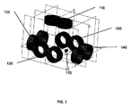
図1は、本明細書で説明するようなTMSシステムの一部として使用することができる5つの電磁石110、120、130,140、及び150を組み込んだ構成を示している。電磁石は同じサイズである必要はなく、互いに同様の関係にある必要もない。電磁石は、(ガントリ又はロボットアーム上などの)群として及び/又は互いに関連しながら時間とともに動くことができる。例えば、電磁石を刺激(TMS)中に動かすこともでき、又は刺激中に固定することもできる。図1には、標的神経(脳)組織部位170を示している。この部位は、電磁石から等距離にある必要はない。2又はそれ以上の電磁石を含む必要があり、図2及び図3に示す実施形態の説明では4つの電磁石が組み込まれている。
FIG. 1 shows a configuration incorporating five
一般に、本明細書で説明する装置及びシステムを使用して脳の1又はそれ以上の部位を刺激することができる。本明細書で使用する場合、脳部位の「刺激」とは、脳部位から1又はそれ以上の(又は一連の)活動電位を誘発することを意味することができる。これらの装置及び方法により、特に深部脳部位を刺激することができる。本明細書で使用する場合、「深部脳部位」という語句は、皮質及び皮質下脳部位を意味することもでき、或いは(被験者の皮質の下部の部位などの)皮質下脳部位のみを意味することもできる。いくつかの変形例では、(皮質及び皮質下脳部位、2又はそれ以上の皮質下部位などを含む)複数の脳部位を刺激することができる。例えば、脳の1つの部位上の「θ」パターン(Huangら、2005年)のような複雑なパルスリズムにより、脳の別の部分におけるTMS誘発神経調節効果を促進することができる。従って、本明細書で説明するシステムを使用して、1つの部位でこのようなパターンを刺激しながら同時に別の部位を刺激することができる。 In general, the devices and systems described herein can be used to stimulate one or more regions of the brain. As used herein, “stimulation” of a brain region can mean eliciting one or more (or series) of action potentials from the brain region. With these devices and methods, particularly deep brain regions can be stimulated. As used herein, the phrase “deep brain region” can mean the cortical and subcortical brain regions, or only the subcortical brain regions (such as those below the subject's cortex). You can also. In some variations, multiple brain sites (including cortical and subcortical brain sites, two or more subcortical sites, etc.) can be stimulated. For example, complex pulse rhythms such as the “θ” pattern on one part of the brain (Huang et al., 2005) can promote TMS-induced neuromodulatory effects in other parts of the brain. Thus, the system described herein can be used to stimulate such a pattern at one site while simultaneously stimulating another site.
1又はそれ以上の脳部位を刺激するために、本明細書で説明するTMSシステムは、複数の電磁石を制御して複数の電磁石の各々において適切な強度、持続時間及び周波数(刺激の複雑なパターンを含む)のパルスを引き起こすことにより、(単複の)標的脳部位のみが活性化されるようにする。(カムのノッチなどにより)機械的に、又は内蔵の固定、ランダム、又は混合パターンを使用して電子的にパルスを引き起こすことができ、或いはコンピュータ制御によりこのようなパターンを生成することもできる。 In order to stimulate one or more brain regions, the TMS system described herein controls a plurality of electromagnets so that each of the plurality of electromagnets has the appropriate intensity, duration and frequency (a complex pattern of stimulation). To cause only the target brain site (s) to be activated. Pulses can be triggered mechanically (such as by a cam notch) or electronically using built-in fixed, random, or mixed patterns, or such patterns can be generated by computer control.
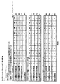
一般に、システムは、システム内の複数の電磁石の各々ごとに適切な発射パターンを生成することができる。「発射パターン」とは、パルスの持続時間、パルスの周波数、及びパルスの強度(強さ)(例えば、パルスを生成するために印加される電流/電圧)を意味することができる。通常、システムは電磁石の全ての発射パターンを制御して調和させる。例えば、(第1の電磁石、第2の電磁石、第3の電磁石などのように)電磁石を順番に発射することもでき、或いは(ランダム又は疑似ランダムを含む)何らかの別の順序で発射することもできる。下の表1には順次発射パターンの例を示しており、表2にはランダム発射を示している。表1では、表の縦列に示す5つの異なる場所A〜Eにおける電磁石が、表の横列に示す時間1〜時間10の工程段階として順番に作動される。この目的は、標的を刺激するパルス数を最大にしながら、所定の電磁石の近くの組織が受け取るパルス数を最小限にして、望ましくない副作用を避けることにある。個々のパルスは、神経膜が再分極しないように十分な持続時間を有する必要がある。例えば、典型的な皮質ニューロンのクロナキシーは450マイクロ秒である。電磁石は、(場所「A」などの)1つの電磁石の場所に近い組織が、異なる場所(場所「B」)からのパルスによってほとんど影響を受けないように物理的に分布される。表1では、場所Aに関しては、時間段階1及び時間段階6においてパルスを引き起こすことができ、従って時間段階10の終わりには、場所Aの電磁石から2つのパルスが神経組織を通過する。場所B〜場所Eの電磁石にも同じ作用が当てはまる。しかしながら、共通の標的は、場所A〜場所Eにおける電磁石近くの組織よりもさらに遠い場所に存在するので、大きさの小さいものもあるが、個々の段階においてパルスを受け取ることになる。説明したように、10の時間段階の終わりには、場所A〜場所Eの電磁石近くの組織は2つのパルスしか受け取らないのに対し、深部の標的は10のパルスを受け取ることになる。
In general, the system can generate an appropriate firing pattern for each of the plurality of electromagnets in the system. “Fire pattern” can mean the duration of a pulse, the frequency of the pulse, and the intensity (intensity) of the pulse (eg, current / voltage applied to generate the pulse). Normally, the system controls and coordinates all firing patterns of the electromagnet. For example, the electromagnets can be fired in sequence (such as a first electromagnet, a second electromagnet, a third electromagnet, etc.) or in some other order (including random or pseudo-random). it can. Table 1 below shows examples of sequential firing patterns, and Table 2 shows random firing. In Table 1, the electromagnets in five different locations A to E shown in the table column are operated in sequence as process steps from
表1:順次発射パターン

本明細書で説明するTMSシステムは、電磁石により印加されるパルスのタイミング、強度及び持続時間だけでなく、発射パターンを調和させる制御論理を含むことができる。この制御論理(コントローラの一部であってもよいし、ハードウェア、ソフトウェアあるいはこれらの両方であってもよい)は、(電磁石に対する1又はそれ以上の標的の場所などの)被験者の標的の生体構造に関する入力、並びに利用可能な電力を示す(単複の)電源の状態に関する情報を受け取ることができる。最後に、標的部位に対して引き起こされる活動電位の所望のレートなどの入力を含むこともできる。同様に追加入力を使用することもできる。これらの入力は、制御論理が、発射パターンをどれにすべきかを含む電磁石の各々における刺激を決定するのに役立つことができる。 The TMS system described herein can include control logic that harmonizes the firing pattern as well as the timing, intensity, and duration of the pulses applied by the electromagnet. This control logic (which may be part of the controller or may be hardware, software or both) is the target's target organism (such as one or more target locations relative to the electromagnet). Information about the structure as well as information about the state of the power supply (s) indicating the available power can be received. Finally, inputs such as a desired rate of action potentials that are caused to the target site may also be included. Similarly, additional inputs can be used. These inputs can help the control logic determine the stimulus at each of the electromagnets, including what firing pattern should be.
ランダム発射パターンの例を表2に示す。この例では、表1に示すパターンと同様に、場所A〜場所Eにおける電磁石近くの組織には正味同じ数のパルスが送達されるのに対し、深部標的は10のパルスを受け取る。順次及びランダム発射パターンを混合して同じ結果を得ることもでき、ある時間段階で2以上のパルスが引き起こされてから次の時間段階に移ることもできる。一部又は全てのパルスを2又はそれ以上の場所から同時に発射することもできる。 An example of a random firing pattern is shown in Table 2. In this example, similar to the pattern shown in Table 1, a net target receives 10 pulses, while the same number of pulses are delivered to the tissue near the electromagnet in locations A-E. Sequential and random firing patterns can be mixed to achieve the same result, and more than one pulse can be triggered at a time step before moving on to the next time step. Some or all of the pulses can be fired simultaneously from two or more locations.
表2:ランダム発射パターン
時間段階1〜nまでの間の時間間隔は、標的神経要素(標的脳部位のニューロン)が再分極する間隔よりも速いレートでパルスを送達するように調節することができ、この高速レートでは、標的神経要素の閾値を超えて所望の効果的な刺激が発生し、活動電位を引き起こすことができる。場所A〜場所nにおける個々の電磁石の発射レート(従って標的場所に送達される複合パルスレート)は、これらの個々の電磁石の数に依存する。例えば、標的において1000Hzのパルスレートを達成するためには、(A〜Eなどの)5つの電磁石が存在する場合、これらの5つの電磁石を各々200Hzの効果的なレートで刺激することにより、これを達成することができる。個々の電磁石が(A〜Cなどの)3つしか存在しなければ、これらの3つの電磁石を各々約333Hzの効果的なレートで刺激することにより、これを達成することができる。この効果を達成するために、電磁石の全てを同じ周波数で発射する必要はない。例えば、標的において1000Hzのパルスレートを得るために、3つの電磁石のうちの2つが400Hzの有効発射レートを有し、第3の電磁石が200Hzの有効発射レートを有することができる。電磁石は同じ種類又はサイズである必要もない。ランダム発射を含むいずれの状況においても、発射の順序のみならず時間間隔も様々であってよい。
The time interval between
システムはまた、(活動電位を発射するレートなどの)標的組織の望ましい刺激のレートを達成するために発射パターンを制御することもできる。例えば、システムは、(1000Hzなどの)高いパルスレートをほんの一瞬の間だけ、例えば5個の電磁石の各々から1つずつの間隔の狭い5つの連続パルスの間だけ到達させ、その後一時停止するように電磁石を制御することができる。このような場合、ニューロンが「1000Hz」パルスのバーストを単一の刺激として経験することができる。(1000Hzなどの)高速の複数電磁石のバーストを(0.2秒などの)十分な待機時間で分離できるとすると、深部標的組織が経験する正味の効果は、さらに遅いペース、例えば5〜50Hzの間になる。低速レート又は高速レートのrTMSの生成において、一時的に加算される複数電磁石のバーストに同じ原理を適用することができる。例えば、たとえ5つの電磁石が各々1000Hzのレートで一回放電しても、(標的組織内で加算されるバーストなどの)重なったバーストを約1秒間で分離しさえすれば、所定の脳の部分が経験する有効パルスレート及び安全プロファイルは1Hzにも満たない。従って、個々の電磁石を、各々(1000Hzなどの)高速の連続(「バースト」)の形で一度発射しても、各バースト間で0.2秒から1秒待機することにより、一時的な加算を得るとともに通常のrTMSレートの安全性も得ることができる。 The system can also control the firing pattern to achieve the desired rate of stimulation of the target tissue (such as the rate at which the action potential is fired). For example, the system may cause a high pulse rate (such as 1000 Hz) to be reached for a moment, for example, 5 consecutive narrow pulses, one from each of 5 electromagnets, and then paused. The electromagnet can be controlled. In such cases, the neuron can experience a burst of “1000 Hz” pulses as a single stimulus. Given that fast bursts of multiple electromagnets (such as 1000 Hz) can be separated with sufficient waiting time (such as 0.2 seconds), the net effect experienced by the deep target tissue is at a slower pace, eg, 5-50 Hz. Between. The same principle can be applied to bursts of multiple electromagnets that are temporarily added in the generation of low rate or high rate rTMS. For example, even if five electromagnets each discharge once at a rate of 1000 Hz, as long as overlapping bursts (such as bursts summed in the target tissue) are separated in about 1 second, a given brain segment The effective pulse rate and safety profile experienced by is less than 1 Hz. Thus, even if each electromagnet is fired once in the form of a high-speed continuous ("burst") each (such as 1000 Hz), a temporary addition is achieved by waiting from 0.2 to 1 second between each burst. As well as the safety of normal rTMS rates.
従って、本明細書で説明するTMSシステムは、個々の電磁石(又は一群の電磁石)の個々の発射レート、持続時間及び強度を制御する一方で、全体的な刺激パターンに注意を払うことができる。一般に、標的組織の刺激は、標的組織において印加される電磁場の効果の時間的及び空間的加算により生じる。従って、システムは、個々の電磁石の発射が、非標的組織にとっては閾値下エネルギーであるが、標的組織に集中されたエネルギーは閾値を上回るように、電磁石の全ての適切な発射パターン、並びに個々の電磁石の個々の発射(強度、持続時間及びレート)を決定することができる。示すように、システムにより印加される電力を制御することは、この制御の一部である。一般に、個々の電磁石は、単一の電源、複数の電源により給電を受けることができ、或いは1つの電源を使用して複数の電磁石に給電することもできる。 Thus, the TMS system described herein can pay attention to the overall stimulation pattern while controlling the individual firing rate, duration and intensity of individual electromagnets (or a group of electromagnets). In general, stimulation of the target tissue occurs by temporal and spatial addition of the effect of the electromagnetic field applied at the target tissue. Thus, the system ensures that all appropriate firing patterns of the electromagnet, as well as individual, are such that the firing of the individual electromagnets is sub-threshold energy for non-target tissue, but the energy focused on the target tissue is above the threshold. The individual firing (intensity, duration and rate) of the electromagnet can be determined. As shown, controlling the power applied by the system is part of this control. In general, each electromagnet can be powered by a single power supply, multiple power supplies, or can be powered by a single power supply.
図2は、電磁石のための電力が単一のエネルギー源により供給されるTMSシステムの実施形態を示している。電源200の1つの出力が、接続220を介して電磁石230の全てに共通して供給される。この図では4つの電磁石230を示しているが、適用される配置内で実現可能なあらゆる数に給電を行うことができる。個々の電磁石の発射が刺激コントローラ250により決定され、この結果分配器260が起動して適切なドライバ280を選択し、このドライバ280は、所定の時間に選択された場合、電源200から接続210を介し、接続290を介して関連する電磁石へ電力を送達する。
FIG. 2 shows an embodiment of a TMS system in which the power for the electromagnet is supplied by a single energy source. One output of the
図3は、電磁石が個々の電源により電力を供給される実施形態を示している。(電源A〜Dなどの)全ての電源300、302、304、306の1つの出力が、接続320を介して全ての電磁石330、332、334、336に共通して供給される。この図では、4つの電磁石330、332、334、336を示しているが、適用される配置内で実現可能なあらゆる数の電磁石に給電を行うことができる。この例では、個々の電磁石の発射が刺激コントローラ350により決定され、この結果分配器360が起動して(ドライバA〜Dなどの)適切なドライバ380、382、384、又は386を選択し、これらのドライバ380、382、384、又は386は、所定の時間に選択された場合、関連する接続390、392、394又は396を介して個々の電源300、302、304又は306から関連する電磁石330、332、334又は336へ電力を送達する。コントローラ350は、非標的部位の刺激を避けながら、標的の刺激を調和させる制御論理を実行することができる。
FIG. 3 shows an embodiment in which the electromagnet is powered by individual power sources. One output of all
図2及び図3に示すいずれの変形例においても、(図2のような)電源又は(図3のような)複数の電源が十分な容量を有している限り、2以上の電磁石を同時にパルス化することができる。上述したように、制御論理は、(単複の)電源の利用可能な容量に基づいて適切な出力を決定することができる。仕様に基づいて、或いは計算又は推定に基づいて、この容量を(1又はそれ以上の入力などにより)直接モニタすることができる。 In any of the modifications shown in FIGS. 2 and 3, two or more electromagnets may be simultaneously used as long as the power source (as shown in FIG. 2) or the plurality of power sources (as shown in FIG. 3) have sufficient capacity. Can be pulsed. As described above, the control logic can determine the appropriate output based on the available capacity of the power supply (s). This capacity can be monitored directly (such as by one or more inputs) based on specifications or based on calculations or estimates.
図4は、上述したように、本発明による、複数のコイルに提供することができる電磁石(コイル)の発射パターン及び励起の制御についての様々な例を示している。電磁石の電荷蓄積装置400は、単一電源法410及び複数電源法420に分類することができる。図4に示すように、単一電源法410は複数のカテゴリに細分類することができる。単一電源に、互いに固定された関係を有するタイミングで複数のコイルの各々へ電荷を送達させるためには、単一電源同期パルス411が使用される。例として、同時(414)パルス、及び非同時(415)パルスを挙げることができる。単一電源非同期パルス412は、単一の電荷蓄積装置からの電荷が、コイル間で共有される時間尺度以外の信号に基づいて個々のコイルが発射するように複数のコイルに計量供給されるものを表現したものである。非同期発射の開始は、例えば1つのコイルから送達される一連のパルスが終了したことを検知することを含むことができる。単一電源独立パルス413は、1つのコイルの活動が他のコイルの活動に同期しておらず、影響も与えないものを表現したものである。このアプローチをうまく使用するためには非常に大きな蓄積電荷容器が必要となる。
FIG. 4 illustrates various examples of electromagnet (coil) firing patterns and excitation control that can be provided to multiple coils according to the present invention, as described above. The electromagnet
複数電源法(420)も複数のカテゴリに細分類することができる。単一電源に、互いに固定された関係を有するタイミングで複数のコイルの各々へ電荷を送達させるためには、複数電源同期パルス421が使用される。例として、同時(424)パルス、及び非同時(426)パルスを挙げることができる。複電源非同期パルス422は、単一の電荷蓄積装置からの電荷が、コイル間で共有される時間尺度以外の信号に基づいて個々のコイルが発射するように複数のコイルに計量供給されるものを表現したものである。非同期発射の開始は、例えば1つのコイルから送達される一連のパルスが終了したことを検知することを含むことができる。複数電源独立パルス423は、1つのコイルの活動が他のコイルの活動に同期しておらず、影響も与えないものを表現したものである。この方法は、電力を任意のコイルに明確に割り当てることができるので、単一電源の場合よりも容易に達成することができる。
The multiple power supply method (420) can also be subdivided into multiple categories. A multiple power
図5は、患者の頭部周囲の(本明細書では3つの「電磁石」と呼ぶ)3つの(二重)刺激コイルの配置を、Voxel−Man 3D Navigatorからの画像データに部分的に基づく画像で示している。被験者の頭部505を平面510で横に切断して示している。(コイルA又は電磁石Aとも呼ばれる)V字形二重コイル520は、円形コイル521及び522から成り、両コイルの電流の戻り経路が同じ向きになる中心部で曲げられる。同様に(コイルB又は電磁石Bとも呼ばれる)V字形二重コイル530は、曲げられた中心部で接合された円形コイル531及び532から成り、(コイルC又は電磁石Cとも呼ばれる)V字形二重コイル540は、曲げられた中心部で接合された円形コイル541及び542から成る。皮質下(又は「深部」)標的域580内(この例では左及び右帯状束)には、標的となる生体構造590、この例では帯状線維束580が存在する。別の実施形態では、電磁石がV字形ではなく伝統的な8字型二重コイルである。さらに別の実施形態では、電磁石の面を横切る軸が全て同じ方向を向いているわけではない。
FIG. 5 shows an image based in part on the image data from a Voxel-Man 3D Navigator, with an arrangement of three (dual) stimulation coils (referred to herein as three “electromagnets”) around the patient's head. Is shown. The subject's
最も近い皮質溝の底部とその下にある深部標的との間の距離は、物理的なコイルの中心間の距離よりも短いと想定される。これらの状況下では、磁場が皮質表面よりも深部標的において高度に加算される。 It is assumed that the distance between the bottom of the nearest cortical groove and the underlying deep target is shorter than the distance between the physical coil centers. Under these circumstances, the magnetic field is highly added at the target deeper than the cortical surface.
1又はそれ以上のコイルを隣接するコイルと同じ極性でパルス化することにより、いくつかの場所に到達する磁束を増やすことができる。反対に、1又はそれ以上のコイルを隣接するコイルと逆の極性でパルス化することにより、いくつかの場所に到達する磁束を打ち消すことができる。例えば、コイル560がコイル550及び570に対してそれぞれ逆バイアスされている場合、コイル550及び570から放出される磁場の内側面を大部分相殺することができる。この作用は、本明細書で説明するTMSシステムによって制御することができ、また標的部位に焦点を合わせる上でも役立つことができる。
By pulsing one or more coils with the same polarity as the adjacent coils, the magnetic flux reaching several locations can be increased. Conversely, by pulsing one or more coils with the opposite polarity to the adjacent coils, the magnetic flux reaching several locations can be canceled out. For example, if the
例えば、本明細書で説明するTMSシステムを使用して、辺縁脳部位に対して高速rTMSパルスレートを、及び深部標的部位に対して低速パルスレートを生成することができる。この刺激パターン(及び結果として得られる発射パターン及び電磁石に対する命令セット)は、被験者が疼痛又はうつ病に伴うOCDの治療を受けているような状況において、運動皮質又は前頭葉の代謝速度を増加させる一方で背側前帯状束の代謝速度を減少させるのに特に有用であると思われる。パルスが、高速ではあるものの標的のクロナキシーを超える時間間隔の間ねじれると、高速刺激効果は個々のコイル近くに見当合わせされるが、辺縁からの時間的にねじれたパルスに起因して、エネルギー経路の交点における標的で加算が行われない。辺縁からの(1秒あたり1つなどの)いくつかのパルスを時間的に同時発生させる(或いは深部標的ニューロンのクロナキシー時間内に入るように高速連続の形で発生させる)ことにより、辺縁の部位において高速刺激レートを達成しながら深部標的において低速レートを達成することができる。 For example, the TMS system described herein can be used to generate fast rTMS pulse rates for marginal brain sites and slow pulse rates for deep target sites. This stimulation pattern (and resulting firing pattern and instruction set for the electromagnet) increases the motor cortex or frontal lobe metabolic rate in situations where the subject is being treated for OCD associated with pain or depression. It appears to be particularly useful in reducing the metabolic rate of the dorsal anterior cingulate bundle. If the pulse is twisted for a time interval that is faster but exceeds the target chronaxy, the fast stimulus effect is registered near the individual coils, but due to the temporally twisted pulse from the edge, the energy No addition is performed at the target at the intersection of the path. By generating several pulses from the edge (such as one per second) in time (or in a fast continuous form so as to fall within the chronaxy time of the deep target neuron) A slow rate can be achieved at a deep target while achieving a fast stimulation rate at the site.
別の例では、脳辺縁部に対して低速rTMSパルスレートを有し、エネルギー経路の交点における深部標的に対して高速パルスレートを有することが臨床的に望ましいと思われる。例えば、注意欠陥多動障害の治療では、前頭葉の過剰な代謝を減らして背側前帯状束の活動を増加させることが望ましいと思われる。コントローラは(電磁石に対する標的の場所を特定する)標的情報を受け取り、刺激前に、又は刺激中にオンザフライで計算を行って望ましい効果を達成することができる。例えば、複数電源の各々からのパルスをねじれた形で送達して、辺縁部のパルスを遅く、エネルギーの交点におけるパルスを速くすることができる。高速レートではあるものの(120%MTなどの)閾値上の低速レートパルスを散在させた(99%MTなどの)閾値下の電力でパルスに給電を行うことにより、エネルギー経路の中心の交点における標的が高速刺激を経験するのに対し、1又はそれ以上のコイルの真下の場所は低速レートの刺激しか経験しないようになる。rTMSのパルスは非常に短い(持続時間が約0.1〜0.3ミリ秒)ので、いくつかの異なるコイル間に分散して非同期的にパルスを送達する高速な流れのパルス間にも多数の時間的「空間」が存在する。 In another example, it may be clinically desirable to have a slow rTMS pulse rate for the margin of the brain and a fast pulse rate for the deep target at the intersection of the energy paths. For example, in the treatment of attention deficit / hyperactivity disorder, it may be desirable to reduce excessive frontal metabolism and increase dorsal anterior cingulate activity. The controller can receive target information (identifying the location of the target relative to the electromagnet) and perform calculations on the fly before or during stimulation to achieve the desired effect. For example, pulses from each of the multiple power supplies can be delivered in a twisted fashion, slowing the edge pulses and speeding the pulses at the energy intersection. Powering the pulse with sub-threshold power (such as 99% MT) that is at a fast rate but interspersed with slow-rate pulses above the threshold (such as 120% MT) allows the target at the center intersection of the energy path Will experience fast stimulation, whereas locations just below one or more coils will experience only slow rate stimulation. Since rTMS pulses are very short (duration about 0.1-0.3 milliseconds), there are many even between fast flow pulses that are distributed across several different coils and delivered asynchronously. There is a temporal “space”.
図6は、3つの閾値に基づく(活動電位誘発対非活動電位誘発)計算を含む望ましい効果を達成するために、図5で示したものと同様のTMSシステムの電磁石の作動の3つの例を例示した表を示している。この表では、「1」という値は、臨界閾値を超えたため活動電位が誘発されたことを意味する。これに対して「0」は、累積効果が臨界閾値を超えなかったため活動電位が誘発されなかったことを意味する。T1〜T10は、このケースでは0.1ms間隔と定義される間隔内のサンプリング時間である。代替の実施形態では、T1〜T10が異なる時間を表すことができる。これらを一定の時間間隔ごとに配置してもよいし、或いはそうでなくてもよい。3つの表の各々において、最も近い皮質溝の底部とその下にある深部標的との間の距離は、物理的なコイルの中心間の距離よりも短いと想定される。これらの状況下では、磁場が皮質表面よりも深部標的において高度に加算される。以下、これらのシナリオの各々において適切な加算がどのような前提により生み出されるのかについて、図8の考察の中でさらに検討する。(コントローラの一部などの)制御論理を使用して、この刺激パターンだけでなく、この刺激パターンを得るのに必要な、各電磁石の給電を含む個々の電磁石により提供される各刺激のパラメータを決定(例えば計算)することができる。 FIG. 6 illustrates three examples of electromagnet operation of a TMS system similar to that shown in FIG. 5 to achieve the desired effect including calculations based on three thresholds (action potential evoked vs. non-action potential evoked). An exemplary table is shown. In this table, a value of “1” means that an action potential has been induced because the critical threshold has been exceeded. On the other hand, “0” means that the action potential was not induced because the cumulative effect did not exceed the critical threshold. T1 to T10 are sampling times within an interval defined in this case as an interval of 0.1 ms. In an alternative embodiment, T1-T10 can represent different times. These may be arranged at regular time intervals or not. In each of the three tables, the distance between the bottom of the nearest cortical groove and the underlying deep target is assumed to be shorter than the distance between the physical coil centers. Under these circumstances, the magnetic field is highly added at the target deeper than the cortical surface. In the following, further discussion will be made in the discussion of FIG. 8 on what assumptions are made for the appropriate addition in each of these scenarios. Using control logic (such as part of the controller), not only this stimulation pattern, but also the parameters of each stimulation provided by the individual electromagnets, including the power supply of each electromagnet, necessary to obtain this stimulation pattern. Can be determined (eg, calculated).
図6に示す3つの表のうちの最初の表では、最上部の表が、コイルA、コイルB、及びコイルCの各々から10個の時間間隔の各々においてパルスが送達されるシナリオを示している。従って、加算される「相互深部標的」は、10Hzの正味深部刺激レートでは個々のパルスにおいて活動電位まで刺激される。この例では、(コイルA、B、及びCから放出されるパルスの交点にある)深部標的部位が、コイルA、B及びCの真下にある表層寄りの皮質部位が刺激される通りに刺激される。 In the first of the three tables shown in FIG. 6, the top table shows a scenario where pulses are delivered from each of coil A, coil B, and coil C in each of 10 time intervals. Yes. Thus, the added “mutual depth targets” are stimulated to action potentials in individual pulses at a net depth stimulation rate of 10 Hz. In this example, the deep target site (at the intersection of the pulses emitted from coils A, B, and C) is stimulated as the surface cortex site just below coils A, B, and C is stimulated. The
図6に示す3つの表のうちの第2の表では、コイルA及びBが高速の10Hzレートでパルス化される一方で、コイルCは低速の1HzレートでT1においてのみパルスされることを示している。これらの間隔の2つのコイルは、加算を生じるには相互深部標的から遠すぎると考えられるので、相互深部標的における出力はT1においてのみ「1」すなわち活動電位であることが示されている。従って、相互深部標的における正味の効果が1Hzの刺激であるのに対し、表層に近い部位は10Hzで刺激される。 The second of the three tables shown in FIG. 6 shows that coils A and B are pulsed at a fast 10 Hz rate, while coil C is pulsed only at T1 at a slow 1 Hz rate. ing. Since the two coils at these intervals are considered too far from the mutual deep target to cause the addition, the output at the mutual deep target is shown to be “1” or action potential only at T1. Thus, the net effect at the mutual deep target is 1 Hz stimulation, while the site near the surface is stimulated at 10 Hz.
図6に示す3つの表のうちの最後の表では、コイルA及びBが高速の10Hzレートでパルス化される一方で、コイルCは中程度の5Hzレートで一回おきの時間間隔でパルス化されることを示している。これらの間隔の2つのコイルは、加算を生じるには相互深部標的から遠すぎると考えられるので、相互深部標的における出力は一回おきの時間間隔においてのみ「1」すなわち活動電位であることが示されている。従って、相互深部標的における正味の効果は5Hzの刺激となる。 In the last of the three tables shown in FIG. 6, coils A and B are pulsed at a fast 10 Hz rate, while coil C is pulsed at every other time interval at a moderate 5 Hz rate. It is shown that. Two coils at these intervals are considered too far from the mutual deep target to cause the addition, indicating that the output at the mutual deep target is “1” or action potential only at every other time interval. Has been. Thus, the net effect on the mutual deep target is a 5 Hz stimulus.
当然ながら、図6では、皮質部位の各々における刺激は、これらの部位の刺激に関して「100%MT」(閾値を超える)と示される。「MT」とは、経頭蓋の磁気刺激を介して反応を誘発するための(運動皮質の刺激に基づく)基準である運動閾値を意味し、「100%MT」又はそれ以上(例えば「115%MT」)で活動電位を誘発することができる。与えられた刺激が閾値未満(<100%MT)であっても、依然として深部脳部位に十分な加算(100%MTまたはそれ以上)を提供することができる。従って、(単複の)深部部位を刺激する一方で、皮質又は深部標的よりも表層の部位を刺激せずに活動電位を発射しないようにすることができる。 Of course, in FIG. 6, the stimulation at each of the cortical sites is indicated as “100% MT” (above threshold) for stimulation of these sites. “MT” means a motor threshold that is a criterion (based on motor cortex stimulation) for eliciting a response via transcranial magnetic stimulation, “100% MT” or higher (eg, “115% MT ") can trigger action potentials. Even if the applied stimulus is below the threshold (<100% MT), it can still provide sufficient addition (100% MT or more) to the deep brain region. Thus, the deep site (s) can be stimulated while the action potential is not fired without stimulating the surface layer over the cortex or deep target.
図7A及び図7Bは、各々が患者の頭部周囲の4つの二重コイルから成り、図5に相互深部標的として示すものと同じ帯状束の標的に集中させている2つの異なる例示的な配置構成を示している。電磁石はTMS治療中に動くことができるので、エネルギーを印加する場所も動くことができる。このようなコイル移動装置は、Schneider及びMishelevichの米国特許出願第10/821,807号に記載されるようなものであってもよい。他の例では、TMSシステムが固定したコイルの配置を含むこともできる。静止コイルを治療前又は治療段階の間に動かす(再配置する)ことができる。 FIGS. 7A and 7B show two different exemplary arrangements, each consisting of four double coils around the patient's head, centered on the same band bundle target as shown in FIG. 5 as a mutual deep target. The configuration is shown. Since the electromagnet can move during TMS treatment, the location where the energy is applied can also move. Such a coil moving device may be as described in Schneider and Michelevic US patent application Ser. No. 10 / 821,807. In other examples, the TMS system may include a fixed coil arrangement. The stationary coil can be moved (repositioned) before or during the treatment phase.
図の上部の図7Aでは、コイル705、710、715及び720が背側前帯状束の標的700から離れすぎた場所にあるため、標的の活動を効果的に調節することができない。しかしながら、下部の図、図7Bに示すようにコイルをより近いパターンに動かすことにより、この配置を効果的に使用できるようになる。図7Bでは、コイル755、760、770及び780が互いにずっと近くに、及び2Dの軸方向の切片に重ね合わせた3Dパターンでは背側前帯状束標的750の近くに移動している。本発明者らが米国特許出願第11/429,504号に記載するように、3又はそれ以上の標準的な平坦TMSコイルを使用して、これらの「平坦面」を互いに直角にすることによってもこの構成を実現することができる。
In FIG. 7A at the top of the figure, the activity of the target cannot be effectively adjusted because the
図8は、図7Bに示すコイルの異なるパルスパターンの効果を、各コイルからの距離、及び(2値変数としてではなく継続的に測定した)磁気パルスの強度、及び介在する表層構造に対する標的構造に及ぼされる効果を考慮して集計(シミュレート)した表である。所定の電磁石の標的までの距離はDTDTであり、これは電磁石からの磁場が通過する皮質溝の底部から測定したセンチメートル単位の「深部標的までの距離」である。減衰係数(FF)とは、以前の位置から1cm移動した後にエネルギー源の何パーセントが存在するかを反映する指数のことである。各時間(Tn)における電力の%は、コイルに印加されるエネルギー(持続時間及び電力)を反映する。図示のように、(電磁石により与えられる複数の刺激の交点における標的である)相互深部標的では、パーセント電力は115%であり、これは閾値上である。TMSに使用できる70mmの二重コイルの場合、この係数は約0.50(50%)である。相互深部標的におけるパーセント電力は、標的の活性化閾値のパーセント又はパーセント運動閾値である。上述したように、(T1、T2...Tnなどの)Tnは任意の時間であり、これらの時間は等間隔であってもよいが、必ずしもその必要はない。相互深部標的におけるパーセント電力は、各Tnにおいて次のように計算することができる。
MDTにおけるパーセント電力=(FFDTDT×Tnにおける%電力)コイルA+(FFDTDT×Tnにおける%電力)コイルB+(FFDTDT×Tnにおける%電力)コイルC+(FFDTDT×Tnにおける%電力)コイルD
FIG. 8 shows the effect of the different pulse patterns of the coils shown in FIG. 7B on the distance from each coil, the intensity of the magnetic pulse (measured continuously, not as a binary variable), and the target structure for the intervening surface structure. It is a table that is aggregated (simulated) in consideration of the effect on the. The distance to a given electromagnet target is DTDT, which is the “distance to the deep target” measured in centimeters from the bottom of the cortical groove through which the magnetic field from the electromagnet passes. The damping factor (FF) is an index that reflects what percentage of the energy source is present after moving 1 cm from the previous position. The percentage of power at each time (T n ) reflects the energy (duration and power) applied to the coil. As shown, for a mutual deep target (which is the target at the intersection of multiple stimuli provided by an electromagnet), the percent power is 115%, which is above the threshold. For a 70 mm double coil that can be used for TMS, this factor is about 0.50 (50%). The percent power at the mutual deep target is the percent of the target activation threshold or the percent exercise threshold. As described above, Tn (such as T1, T2... Tn) is an arbitrary time, and these times may be equally spaced, but are not necessarily required. The percent power at the mutual deep target can be calculated at each Tn as follows:
Percent power at MDT = (% power at FF DTDT × T n ) Coil A + (% power at FF DTDT × T n ) Coil B + (% power at FF DTDT × T n ) Coil C + (FF DTDT × T n % Power) in coil D
帯状束は偶然ながら正中線に近い左右対称構造であるので、標的が(計算の簡単にするため)2つの帯状束間の点であるとした場合、このような距離を左右両方の帯状束構造に使用することができる。表に示す特定の値で例示する特定のシナリオでは、下にある溝が標的から2.5cmのところにある2つのコイルに、下にある溝が標的から0.5cmのところにある2つのコイルを加えて使用した場合、標的において運動閾値の115%を生じるためには各コイルから65%の電力しか必要としないことが示されている。当然ながら、多くの他の電力/距離要件をこの図に示す方法で決定することができる。この表が示す方法の変形例を使用して、一度に1つの標的のみに及ぼされる効果を、この標的のエネルギー源の各々からの距離に基づいて別個に計算することもできる。 The band-like bundle happens to be a symmetrical structure close to the midline, so if the target is a point between two band-like bundles (for the sake of simplicity of calculation), this distance is used for both the right and left band-like bundle structures. Can be used for In the specific scenario illustrated by the specific values shown in the table, two coils with the underlying groove 2.5 cm from the target and two coils with the underlying groove 0.5 cm from the target When used in addition, it has been shown that only 65% of power is required from each coil to produce 115% of the motion threshold at the target. Of course, many other power / distance requirements can be determined in the manner shown in this figure. Using a variation of the method shown in this table, the effect on only one target at a time can be calculated separately based on the distance from each of the target's energy sources.
上述したように、通常、本明細書で説明する経頭蓋磁気刺激システム(TMS)はいずれも、各電磁石が個別に制御又は命令されるように構成される。従って、これらのシステムは各個々の電磁石を明確に調和させるコントローラを含むことができ、個々の電磁石が、他の電磁石から独立して機能できるように構成されることにより、各電磁石が他の電磁石から分離した刺激プロトコルを実行できるようになる。別個の構成要素又はシステム内の内蔵構成要素であってもよいコントローラは、ハードウェア及びソフトウェア(又はファームウェア)の両方を含むことができ、通常は各電磁石を制御するための命令を含む刺激法を実行する。これらの命令は、発射の位置、周波数又はレート、発射の強度、発射の持続時間、印加する電圧/電流の(波形などの)形、(角度及び/又は患者からの距離、患者周囲における配向、及び変形例によっては電磁石の動きなどの)位置、及び電磁場の方向の制御を含むことができる。コントローラにより実行される刺激を制御するための命令を治療計画又は治療法と呼ぶこともできる。各電磁石の作動を制御することに加え、治療法はまた、個々の電磁石の発射パターンを示す刺激パターンを含むこともできる。本明細書で使用する場合、「個々の」電磁石は、電磁石の(対などの)セットを含むことができる。 As described above, typically, any transcranial magnetic stimulation system (TMS) described herein is configured such that each electromagnet is individually controlled or commanded. Thus, these systems can include a controller that specifically harmonizes each individual electromagnet, and each electromagnet is configured to be able to function independently of the other electromagnet, thereby allowing each electromagnet to function with the other electromagnet. It becomes possible to execute the stimulation protocol separated from The controller, which may be a separate component or a built-in component in the system, can include both hardware and software (or firmware), and typically includes a stimulation method that includes instructions for controlling each electromagnet. Execute. These instructions include the location of the firing, frequency or rate, firing strength, duration of firing, shape of applied voltage / current (such as waveform), angle (and / or distance from patient, orientation around patient), And, in some variations, control of position (such as electromagnet movement) and the direction of the electromagnetic field. The instructions for controlling the stimulation performed by the controller can also be referred to as a treatment plan or treatment. In addition to controlling the operation of each electromagnet, the therapy may also include a stimulation pattern that indicates the firing pattern of the individual electromagnets. As used herein, “individual” electromagnets can include sets (such as pairs) of electromagnets.
いくつかの変形例では、コントローラが、治療法を生成するための論理(ハードウェア及び/又はソフトウェア)も含む。或いは、治療法を計算するための別個のモジュール又は構成要素を使用することもできる。例えば、スケジューリング論理を使用して1又はそれ以上の治療法を生成することができる。図9は治療法を生成する1つの方法を示すフロー図である。一般に、この治療法は、まず個々の標的部位ごとに、並びに電磁石と標的との間の脳部位のような、電磁石の作動により影響を受ける可能性がある他のあらゆる部位の治療方針を決定(又はユーザ入力などにより入力)することにより考案される。 In some variations, the controller also includes logic (hardware and / or software) for generating the therapy. Alternatively, a separate module or component for calculating therapy can be used. For example, scheduling logic can be used to generate one or more treatments. FIG. 9 is a flow diagram illustrating one method for generating a therapy. In general, this therapy first determines the treatment strategy for each individual target site, as well as any other site that may be affected by the operation of the electromagnet, such as the brain region between the electromagnet and the target ( Or input by user input or the like).
図9を参照すると、本明細書で説明するシステムなどのTMSシステムを制御する上での第1のステップが、刺激を受ける(単複の)脳組織標的を決定するステップを含む(1001)。あらゆる適切な標的を選択することができる。(うつ病の治療などの)所望の治療効果に基づいて(皮質下の標的などの)深部脳部位の標的を選択することができる。(座標を与えるような)数字、(被験者の脳のスキャン上に示すような)図形、又は他のあらゆる適切な手段により、選択された被験者の脳の深部標的部位をシステムのコントローラ(又は他のモジュール)に提供することができる。例えば、システムは脳のスキャニング又はマッピングを含むことができ、或いは脳のスキャニング又はマッピングから入力を受け取ることができる。例えば、システムは電磁石の位置に対する(単複の)標的の位置又は座標を受け取ることができる。(深部脳標的などの)(単複の)一次標的を決定すると、システムはどの二次標的が標的部位の刺激により影響を受けるかを判断することができる。二次標的は、目的とする標的でないにもかかわらず、目的とする標的を刺激しようとする最中に刺激されることがあるため、偶発的標的又は付随的標的と呼ぶこともできる。例えば、電磁石から放出されるパルスの経路に沿った深部脳部位と電磁石との間の皮質部位は、二次標的又は付随的標的と見なすことができる。場合によっては、付随的標的を一次標的としてもよい。 Referring to FIG. 9, a first step in controlling a TMS system, such as the system described herein, includes determining a brain tissue target (s) to be stimulated (1001). Any suitable target can be selected. A deep brain site target (such as a subcortical target) can be selected based on a desired therapeutic effect (such as treatment of depression). The system's controller (or other device) can select the deep target site of the selected subject's brain by a number (such as giving coordinates), a graphic (as shown on a scan of the subject's brain), or any other suitable means. Module). For example, the system can include brain scanning or mapping, or can receive input from brain scanning or mapping. For example, the system can receive the position or coordinates of the target (s) relative to the position of the electromagnet. Having determined the primary target (s) (such as deep brain targets), the system can determine which secondary targets are affected by the stimulation of the target site. A secondary target may be referred to as an accidental or incidental target because it may be stimulated while attempting to stimulate the target of interest, even though it is not the target of interest. For example, a cortical site between a deep brain site and an electromagnet along the path of a pulse emitted from an electromagnet can be considered a secondary target or an incidental target. In some cases, the incidental target may be the primary target.
被験者の周囲の電磁石(コイル)の位置を調整することもできる。例えば、標的となる(単複の)深部脳部位が選択されると、被験者の頭部周囲のコイルを標的により良好に到達するように動かすことができる。いくつかの変形例では、磁石を連続的に動かして(例えば、回転させて、傾けて、又は別様に再配置して)(単複の)標的部位に到達するようにすることができる。この動きは、コントローラにより調和又は制御することができ、治療の開始時に行うこともできれば、或いは治療中に連続的に又は周期的に行うこともできる。このようにして、治療法は磁石の位置及び/又は動きの制御を含むことができる。 The position of the electromagnet (coil) around the subject can also be adjusted. For example, once the target deep brain region (s) is selected, the coil around the subject's head can be moved to better reach the target. In some variations, the magnet can be continuously moved (eg, rotated, tilted, or otherwise repositioned) to reach the target site (s). This movement can be coordinated or controlled by the controller and can be done at the start of the treatment or continuously or periodically during the treatment. In this way, the therapy can include control of magnet position and / or movement.
一次標的部位及び付随的又は二次標的部位が特定されると、次にシステムは、一次及び二次標的に対する方針を決定することができる(1003)。この方針は、(医師、技術者などの)ユーザからの入力であってもよく、及び/又は方針のデータベースから選択してもよい。いくつかの変形例では、(標的部位などの)特定の部位に対する方針を、(5Hz、50Hz、100Hz、200Hz、500Hzなどの)設定した周波数又は周波数の範囲又は(遅延期間で分離されたパルスのバーストなどの)事前に設定したパターンにおける刺激などの、所望の刺激のレベルとして表すことができる。いくつかの変形例では、方針を「上向き調節」、「下向き調節」又は「刺激なし」のように大まかに特徴づけることもできる。例えば、刺激なしの方針は、(付随的標的部位などの)標的部位を限定して(その部位に対する100%MT未満の刺激などの)電磁石からの閾値刺激が行われないようにすることであると解釈することができる。従って、パルスはその標的部位を通過することができるが、この部位で100%MTを達成してはいけない。同様に、特定の部位における「上向き調節」という方針は、標的部位内における約5Hz又はそれ以上の周波数での刺激を意味することができる。同様に、標的部位での「下向き調節」という方針は、1Hz又はそれ未満のレートでの刺激を意味することができる。複数の異なる脳部位に対する刺激方針の一覧又はデータベースを使用して(及びシステムの一部として含めて)、調整可能な初期値又は事前設定をシステムに提供することができる。例えば、付随的標的に関する調整可能な初期値は刺激なしにすることができる。 Once the primary target site and incidental or secondary target sites are identified, the system can then determine a strategy for the primary and secondary targets (1003). This policy may be input from a user (such as a doctor, technician, etc.) and / or selected from a database of policies. In some variations, the strategy for a particular site (such as a target site) can be set to a set frequency or range of frequencies (such as 5 Hz, 50 Hz, 100 Hz, 200 Hz, 500 Hz) or of pulses separated by a delay period. It can be expressed as the level of the desired stimulus, such as a stimulus in a preset pattern (such as a burst). In some variations, the strategy may be roughly characterized as “upward adjustment”, “downward adjustment”, or “no stimulation”. For example, a no-stimulus strategy is to limit the target site (such as an incidental target site) to prevent threshold stimulation from the electromagnet (such as a stimulus of less than 100% MT for that site). Can be interpreted. Thus, the pulse can pass through its target site, but 100% MT must not be achieved at this site. Similarly, the strategy of “upward adjustment” at a particular site can mean stimulation at a frequency of about 5 Hz or higher within the target site. Similarly, the strategy of “downward adjustment” at the target site can mean stimulation at a rate of 1 Hz or less. Using a list or database of stimulation strategies for multiple different brain sites (and included as part of the system), adjustable initial values or presets can be provided to the system. For example, the adjustable initial value for the incidental target can be unstimulated.
標的又は標的の方針が選択されると、次にシステムは刺激法を決定するための方法を適用する。このような方法の変形例の1つを、図9のステップ1005〜1019に示している。例えば、システムは、目標とする方策を適用することにより(m個の方策の候補などの)複数の方策の候補を生成し(1005)、その後これらの方策の適用をシミュレートした後でスコアを付け、一番スコアの高い治療法を適用する。 Once a target or target strategy is selected, the system then applies a method for determining a stimulation method. One variation of such a method is shown in steps 1005-1019 of FIG. For example, the system generates (1005) multiple policy candidates (such as m policy candidates) by applying a target policy, and then scores the score after simulating the application of these policies. Apply the treatment with the highest score.
図11は、ステップ1005及び1007に示すように、方策の候補のパラメータを選択する方法の1つの例示を示している。一般に、治療法の最中に磁石ごとにパラメータを選択するステップは、システム内の個々の磁石を発射するタイミングを調和させる刺激パターンを生成するステップを含むことができる。上述したように、この刺激パターンは、固定、ランダム、又は混合したものであってもよい。さらに、刺激パターン中の個々の電磁石の発射特性を、強度、持続時間、適用する波形、電磁石の位置、磁場の方向などを含めて選択することができる。これらのパラメータ(刺激パターン及び発射特性)は、標的及び標的の方針により制約を受けることがある。例えば、図11のステップ2001〜2027は、目標数の刺激法の候補を生成するステップを決定する方法の変形例について説明するものである。例えば、異なる順列の刺激パターン2003に関して強度、持続時間、レート、磁場の方向などの順列を決定することができ(2005)、これらをシミュレートして(2015)、これらが一次及び付随的標的の両方に関して標的の方針を達成するかどうかを判定することができる(2017)。この過程は、一連の方策の候補(又は、この過程中にこれらがスコア付け及び比較された場合、一番優れた方策の候補)が特定されるまで反復して繰り返すことができる。いくつかの変形例では、治療法の候補を決定するための起点として事前設定又は過去の治療法を適用又は使用することができる。例えば、特定の標的に関する治療法のデータベースを使用することができる。従って、いくつかの変形例では、システムがこのようなデータベースを含むことができ、さらにこのデータベースに追加を行ったり、或いはこれを修正したりすることができる。
FIG. 11 shows one example of a method for selecting candidate parameters for a strategy, as shown in
(図11に示すような治療計画の決定中、又は図9に示すような治療計画のスコア付け中などにおける)治療計画の候補のシミュレーションは、個々の標的部位内で印加する(単複の)パルスの(時間的及び空間的の両方の)加算の適用に基づくことができる。例えば、上述した図8で示すように、シミュレートした刺激値のマトリクスを生成して、どの刺激レート及び刺激レベルにするかを標的部位ごとに決定し、その後これをこの標的部位に関する方針と比較することができる。従って、このシミュレーションは、電磁石に対する標的部位の位置に基づいて減衰係数を適用することができる。いくつかの変形例では、(部位の減衰係数、刺激の部位閾値、特定の部位における磁場の方向の影響などの)特定の組織の特徴を適用することもできる。 Simulation of treatment plan candidates (such as during treatment plan determination as shown in FIG. 11 or during treatment plan scoring as shown in FIG. 9) is applied to the pulse (s) applied within each target site. Can be based on the application of (both temporal and spatial) addition. For example, as shown in FIG. 8 above, a simulated stimulus value matrix is generated to determine for each target site which stimulus rate and stimulus level is to be compared to this target site policy. can do. Therefore, this simulation can apply an attenuation coefficient based on the position of the target site relative to the electromagnet. In some variations, specific tissue features (such as site attenuation coefficient, stimulation site threshold, influence of magnetic field direction at a particular site) may be applied.
図10は、Talairach Atlasが提供した図を改変したものであり、皮質溝底部から深部標的までの、このケースでは帯状束までの距離を計測するものである。脳901は、脳回902(代表例)、脳溝903(代表例)、及び大脳縦裂904を含む。通常、脳溝903及び大脳縦裂904は透明な脳脊髄液(図示せず)で満たされる。脳脊髄液は主に塩化ナトリウムを含む水から成り、このためこれらの空間は高度に導電性となる。脳901の内部には、主に灰白質ではあるが、軸策から成る帯状束910又は白質も含む帯状回も存在する。(帯状束911などの)深部標的と、2つの近接する高度に導電性の脳溝の底部との間の距離、つまり距離911及び距離920は比較的短い。距離911及び距離920をセンチメートルで表す場合、これらを図8の表との関連においてDTDT(深部標的までの距離)の数字として使用することができる。状束は偶然ながら正中線に近い左右対称構造であるので、標的が2つの帯状束間の点であるとした場合、このような距離を左右両方の帯状束構造に使用することができる。
FIG. 10 is a modification of the diagram provided by Talairach Atlas, measuring the distance from the bottom of the cortical groove to the deep target, in this case the band bundle. The
説明した方法によれば、たとえ(コイルなどの)異なる供給源の動作に根本的な違いがあるとしても、様々な場所における正味の結果を依然として予測して制御することができる。高速又は低速の刺激のいずれかを共通深部標的に与えながら、高速及び低速の刺激レートを辺縁の神経組織に同時に与えることができる。図示の電磁石の例はV字形の二重TMSコイルであるが、本方法は、以下に限定されるわけではないが、標準的(平坦)二重TMSコイル又は環状TMSコイルを含むあらゆる神経刺激エネルギー源に対して一般的なものであることが意図される。本方法はまた、以下に限定されるわけではないが、埋め込み型、外付け型、又は自然開口部内に配置することができる直流又は交流電極、視覚神経刺激光源、及び超音波放射源を含む神経刺激エネルギー源に一般的に適用されることも意図される。 According to the described method, even if there is a fundamental difference in the operation of different sources (such as coils), the net results at various locations can still be predicted and controlled. While applying either fast or slow stimulation to the common deep target, fast and slow stimulation rates can be simultaneously applied to the marginal nerve tissue. The illustrated electromagnet example is a V-shaped dual TMS coil, but the method is not limited to the following, but any neural stimulation energy including a standard (flat) dual TMS coil or an annular TMS coil. It is intended to be general to the source. The method also includes but is not limited to nerves including direct or alternating electrodes that can be placed in an implantable, external or natural opening, a visual nerve stimulation light source, and an ultrasound radiation source. It is also intended to be generally applied to stimulation energy sources.
上述した様々な実施形態は、例示のみの目的で提供したものであり、本発明を限定するものであると解釈すべきではない。上記の考察及び例示に基づいて、当業者であれば、本明細書で例示及び説明した例示的な実施形態及び応用に厳密に従うことなく、本発明に様々な修正及び変更を行えることを容易に理解するであろう。このような修正及び変更は、以下の特許請求の範囲に記載する本発明の真の思想及び範囲から逸脱するものではない。 The various embodiments described above are provided by way of illustration only and should not be construed to limit the invention. Based on the above considerations and examples, those skilled in the art will readily be able to make various modifications and changes to the present invention without strictly following the exemplary embodiments and applications illustrated and described herein. You will understand. Such modifications and changes do not depart from the true spirit and scope of the invention as set forth in the following claims.
参照文献
Huang、Y−Z、Edwards、MJ.Rounia、Elizabeth、Bhatia、K.P.、及びJ.C.Rothwellの「ヒト運動皮質のθバースト刺激」Neuron第45巻201〜206頁、2005年。
米国特許出願第10/821,807号「深部の集中的な経頭蓋磁気刺激を標的としてそれを生成するためのロボット装置」Schneider MB及びMishelevich DJ。
Mishelevich DJ、Schneider MB、米国特許出願第11/429、504号「軌道に基づく深部脳定位経頭蓋電磁刺激」国際特許WO2007130308 20071115号。
Ruohonen J、Ilmoniemi RJ.の「複数のコイルを使用する電磁脳刺激の焦点化及び標的化」Med.Biol eng.Comput、1998年第36巻297〜301頁。
Ruohonen J、Ravazzani P、Grandori F、Ilmoniemi R.の「多重チャネル磁気刺激の理論 機能的筋神経の回復へ向けて」IEEE Transactions on biomedical Engineering第46巻第6号、1999年6月、646〜651頁。
Han B、Chun IK、Lee SC、Lee SY.の「刺激コイルの相互結合を考慮した多重チャネル磁気刺激システムの設計」IEEE Transactions on Biomedical Engineering第51巻第5号、2004年5月、812〜817頁。
Mishelevich DJ、Schneider MB.の「1又はそれ以上のエネルギー源から複数の個別に作動される電磁石をパルス化する方法」USPTO第60970958号、09/09/07。
Schneider MB、Mishelevich DJの「経頭蓋磁気刺激のための標的に特化したコイル構成」USPTO第60990300号、11/27/07。
Isenberg K、Downs D、Pierce K、Svarakic D、Garcia K、Jarvis M、North C、Kormos TC.の「抗うつ剤非投与、治療抵抗性のうつ患者には右前頭皮質の低周波数rTMS刺激が、左前頭皮質の高周波数rTMS刺激と同等に効果的である。」Ann Clin Psychiatry.2005年7月〜9月第17巻第3号153〜9頁。
Talairach J、Tournoux P(1988年)の「ヒト脳の同一平面定位アトラス」Thieme、New York。
Voxel−Man 3D Navigator(Voxel‐Man 3D Navigator)第2.0版 Karl Heinz Hohne及びSpringer Verlag Electronic Media.ハイデルベルク、ドイツ 2001年。
References Huang, YZ, Edwards, MJ. Rounia, Elizabeth, Bhatia, K.M. P. , And J.A. C. Rothwell, “Theta Burst Stimulation of Human Motor Cortex” Neuron 45, 201-206, 2005.
US patent application Ser. No. 10 / 821,807, “Robot Device for Targeting and Generating Deep Intensive Transcranial Magnetic Stimulation” Schneider MB and Michelevich DJ.
Mischelevich DJ, Schneider MB, US patent application Ser. No. 11 / 429,504, “Orbital Deep Brain Stereotactic Transcranial Electromagnetic Stimulation” International Patent WO 2007130308 20071115.
Ruohonen J, Ilmoniemi RJ. "Focusing and targeting electromagnetic brain stimulation using multiple coils" Med. Bioeng eng. Comput, 1998, 36, 297-301.
Ruohonen J, Ravazzani P, Grandori F, Ilmoniemi R. "Theory of Multi-Channel Magnetic Stimulation Toward Functional Muscle Recovery" IEEE Transactions on bioengineering, Vol. 46, No. 6, June 1999, pages 646-651.
Han B, Chun IK, Lee SC, Lee SY. “Multichannel Magnetic Stimulation System Design Considering Mutual Coupling of Stimulation Coils”, IEEE Transactions on Biomedical Engineering Vol. 51, No. 5, May 2004, pages 812-817.
Michelevich DJ, Schneider MB. "Methods for pulsing a plurality of individually actuated electromagnets from one or more energy sources" USPTO No. 60970958, 09/09/07.
Schneider MB, Michelevich DJ's "Targeted Coil Configuration for Transcranial Magnetic Stimulation" USPTO No. 60990300, 11/27/07.
Isenberg K, Downs D, Pierce K, Svarakic D, Garcia K, Jarvis M, North C, Kormos TC. "For patients with antidepressant-free and treatment-resistant depression, low-frequency rTMS stimulation of the right frontal cortex is as effective as high-frequency rTMS stimulation of the left frontal cortex." Ann Clin Psychiatry. July-September 2005,
Talairach J, Tournoux P (1988), “Coplanar stereotaxic atlas of the human brain” Thime, New York.
Voxel-Man 3D Navigator (Voxel-Man 3D Navigator) Version 2.0 Karl Heinz Hone and Springer Verlag Electronic Media. Heidelberg,
Claims (25)
第1の電磁石を第1の持続時間、レート及び電力で発射して、前記被験者の脳を通過する第1の経路に沿って電磁パルスを放出するステップと、
第2の電磁石を第2の持続時間、レート及び電力で発射して、前記被験者の脳を通過する第2の経路に沿って電磁パルスを放出するステップと、
前記第1及び第2の電磁石から放出された電磁パルスの効果を前記被験者の脳の標的深部部位において時間的及び空間的に加算することにより、前記第1及び第2の経路の交点にある前記被験者の脳の標的深部部位に刺激を引き起こすステップと、
を含むことを特徴とする方法。 Transcranial magnetic stimulation (TMS) for stimulating neural tissue deep in a subject's brain by firing a plurality of electromagnets placed at different locations around the subject's head,
Firing a first electromagnet at a first duration, rate and power to emit electromagnetic pulses along a first path through the subject's brain;
Firing a second electromagnet at a second duration, rate and power to emit electromagnetic pulses along a second path through the subject's brain;
The effects of the electromagnetic pulses emitted from the first and second electromagnets are added at the intersection of the first and second paths by adding temporally and spatially at the target deep part of the subject's brain. Causing a stimulus to a deep target site in the subject's brain;
A method comprising the steps of:
前記第2の電磁石を発射するための第2の持続時間、レート及び電力を決定するステップと、
をさらに含み、
前記第1及び第2の持続時間、レート及び電力が、減衰係数、及び前記第1及び第2の電磁石から前記被験者の脳の前記標的深部部位までの距離に基づいて決定される、
ことを特徴とする請求項1に記載の方法。 Determining a first duration, rate and power for firing the first electromagnet;
Determining a second duration, rate and power for firing the second electromagnet;
Further including
The first and second durations, rate and power are determined based on an attenuation coefficient and a distance from the first and second electromagnets to the target deep region of the subject's brain,
The method according to claim 1.
ことをさらに特徴とする請求項1に記載の方法。 Firing the first electromagnet fires the first electromagnet at a first duration, rate and power that does not cause stimulation of neural tissue located on the surface relative to the target deep tissue site. including,
The method of claim 1, further characterized by:
ことをさらに特徴とする請求項1に記載の方法。 Firing the second electromagnet fires the second electromagnet at a second duration, rate and power that does not cause stimulation of neural tissue located superficially with respect to the target deep tissue site. including,
The method of claim 1, further characterized by:
ことを特徴とする請求項1に記載の方法。 The first duration, rate and power are different from the second duration, rate and power;
The method according to claim 1.
ことを特徴とする請求項1に記載の方法。 Firing the first electromagnet includes firing the first electromagnet from a stationary electromagnet that is not configured to move during TMS treatment.
The method according to claim 1.
ことを特徴とする請求項1に記載の方法。 Firing the first electromagnet includes firing the first electromagnet from a movable electromagnet configured to move during TMS treatment.
The method according to claim 1.
ことを特徴とする請求項1に記載の方法。 Firing a third electromagnet at a third duration, rate and power to emit electromagnetic pulses along a third path through the subject's brain, the third path comprising: Intersects the first, second and third pathways at a target deep site of the subject's brain,
The method according to claim 1.
ことを特徴とする請求項8に記載の方法。 The step of inducing stimulation in the target deep part of the subject's brain includes the effect of the electromagnetic pulses emitted by the first, second and third electromagnets temporally and spatially in the target deep part of the subject's brain. Further comprising the step of adding,
The method according to claim 8, wherein:
ことを特徴とする請求項1に記載の方法。 Initiating stimulation at a pre-set rate in the target deep site of the subject's brain by firing a burst of electromagnetic pulses from the first and second electromagnets that add up and cause stimulation in the target deep site The bursts of pulses are separated in a waiting period, during which the electromagnetic pulses from the first and second electromagnets are not added at the target deep site and do not cause irritation,
The method according to claim 1.
ことを特徴とする請求項1に記載の方法。 Firing the first electromagnet and firing the second electromagnet include feeding the first electromagnet and the second electromagnet from a first power source;
The method according to claim 1.
ことを特徴とする請求項1に記載の方法。 Firing the first electromagnet and firing the second electromagnet include feeding the first electromagnet and the second electromagnet from a plurality of different power sources;
The method according to claim 1.
深部脳標的を選択するステップと、
前記深部脳標的、及び該深部脳標的と前記電磁石の各々との間の脳構造に相当する複数の付随的標的の治療方針を決定するステップと、
前記治療方針を達成するように構成され、前記電磁石の発射の刺激パターンと、前記電磁石の各々を前記刺激パターンで発射するための個別の制御命令セットとを含む治療法を生成するステップと、
前記複数の電磁石に前記治療法を適用するステップと、
を含むことを特徴とする方法。 Transcranial magnetic stimulation (TMS) for stimulating neural tissue deep in a subject's brain by firing a plurality of electromagnets arranged at different locations around the subject's head,
Selecting a deep brain target;
Determining a treatment strategy for the deep brain target and a plurality of incidental targets corresponding to brain structures between the deep brain target and each of the electromagnets;
Generating a therapy comprising a stimulation pattern of firing of the electromagnets and a separate set of control instructions for firing each of the electromagnets with the stimulation pattern;
Applying the treatment to the plurality of electromagnets;
A method comprising the steps of:
ことを特徴とする請求項13に記載の方法。 Determining a treatment strategy for the deep brain target and the plurality of incidental targets includes referencing a database of suggested treatment strategies based on the target site;
The method according to claim 13.
ことを特徴とする請求項13に記載の方法。 Determining the treatment strategy includes setting the incidental treatment policy without upward adjustment, downward adjustment or stimulation.
The method according to claim 13.
ことを特徴とする請求項13に記載の方法。 Generating the treatments includes generating a plurality of treatment candidates, simulating individual treatment candidates, and individual simulated strategies based on the achievement of the treatment strategy Scoring candidates and selecting the therapy from the scored strategy candidates.
The method according to claim 13.
ことを特徴とする請求項13に記載の方法。 Applying the therapy comprises controlling individual electromagnets to execute individual control commands of the electromagnets;
The method according to claim 13.
ことを特徴とする請求項13に記載の方法。 Adjusting the position of the electromagnet to focus on the deep brain target;
The method according to claim 13.
第1の電磁石を第1の刺激パターンで発射して、複数の電磁パルスが第1の経路に沿って放出されるようにするステップと、
第2の電磁石を第2の刺激パターンで発射して、複数の電磁パルスが第2の経路に沿って放出されるようにするステップと、
前記被験者の脳の標的深部部位において、前記第1及び第2の電磁石により放出される前記電磁パルスの効果を時間的に加算することにより、前記第1及び第2の経路の交点にある前記被験者の脳の前記標的深部部位において刺激パターンを引き起こすステップと、
を含むことを特徴とする方法。 Transcranial magnetic stimulation (TMS) for stimulating neural tissue deep in a subject's brain by firing a plurality of electromagnets arranged at different locations around the subject's head,
Firing a first electromagnet in a first stimulation pattern such that a plurality of electromagnetic pulses are emitted along a first path;
Firing a second electromagnet in a second stimulation pattern such that a plurality of electromagnetic pulses are emitted along a second path;
The subject at the intersection of the first and second paths by temporally adding the effects of the electromagnetic pulses emitted by the first and second electromagnets in the target deep region of the subject's brain Causing a stimulation pattern in the target deep region of the brain of
A method comprising the steps of:
前記被験者の頭部周囲に配置されるように構成された複数の電磁石と、
各々が前記電磁石の1つと結合して前記電磁石の励起をゲート制御する複数のドライバと、
前記被験者の脳の標的深部部位において刺激を引き起こすために前記複数の電磁石の各電磁石ごとの発射パターンを決定するように構成された刺激コントローラと、
を含み、前記発射パターンが、前記標的深部組織部位における前記複数の電磁石の発射の効果の時間的及び空間的加算を推定することにより決定される、
ことを特徴とするシステム。 A transcranial magnetic stimulation (TMS) system for stimulating neural tissue deep in a subject's brain,
A plurality of electromagnets configured to be disposed around the subject's head;
A plurality of drivers each coupled to one of the electromagnets to gate excitation of the electromagnet;
A stimulation controller configured to determine a firing pattern for each electromagnet of the plurality of electromagnets to cause stimulation at a target deep site in the subject's brain;
Wherein the firing pattern is determined by estimating a temporal and spatial summation of the firing effects of the plurality of electromagnets at the target deep tissue site.
A system characterized by that.
ことを特徴とする請求項20に記載のシステム。 Further comprising a distributor configured to communicate with each of the stimulation controller and the plurality of drivers, the distributor further configured to command the driver based on control of the stimulation controller;
21. The system of claim 20, wherein:
ことを特徴とする請求項20に記載のシステム。 A power source configured to supply power to the plurality of electromagnets;
21. The system of claim 20, wherein:
ことを特徴とする請求項20に記載のシステム。 Further comprising a plurality of power sources configured to power the plurality of electromagnets;
21. The system of claim 20, wherein:
ことを特徴とする請求項20に記載のシステム。 The stimulation controller is configured to receive an input indicating a location of the target deep site for the plurality of electromagnets;
21. The system of claim 20, wherein:
前記被験者の頭部周囲に配置されるように構成された複数の電磁石と、
各々が前記電磁石の1つと結合して前記電磁石の励起をゲート制御する複数のドライバと、
前記ドライバと通信するように構成され、前記ドライバに命令を出すようにさらに構成された分配器と、
前記分配器と通信するとともに、前記被験者の脳の前記標的深部部位において刺激を引き起こすために前記電磁石の各々の発射パターンを決定するように構成された刺激コントローラと、
を含み、前記発射パターンが、前記標的深部組織部位における前記複数の電磁石の発射の効果の時間的及び空間的加算の推定に基づいて決定される、
ことを特徴とするシステム。 A transcranial magnetic stimulation (TMS) system for stimulating neural tissue deep in a subject's brain,
A plurality of electromagnets configured to be disposed around the subject's head;
A plurality of drivers each coupled to one of the electromagnets to gate excitation of the electromagnet;
A distributor configured to communicate with the driver and further configured to issue instructions to the driver;
A stimulation controller configured to communicate with the distributor and to determine a firing pattern of each of the electromagnets to cause stimulation at the target deep site of the subject's brain;
The firing pattern is determined based on an estimate of the temporal and spatial summation of the firing effects of the plurality of electromagnets at the target deep tissue site.
A system characterized by that.
Applications Claiming Priority (4)
| Application Number | Priority Date | Filing Date | Title |
|---|---|---|---|
| US95692007P | 2007-08-20 | 2007-08-20 | |
| US97095807P | 2007-09-09 | 2007-09-09 | |
| US7748808P | 2008-07-02 | 2008-07-02 | |
| PCT/US2008/073751 WO2009026386A1 (en) | 2007-08-20 | 2008-08-20 | Firing patterns for deep brain transcranial magnetic stimulation |
Publications (2)
| Publication Number | Publication Date |
|---|---|
| JP2010536496A true JP2010536496A (en) | 2010-12-02 |
| JP2010536496A5 JP2010536496A5 (en) | 2011-09-22 |
Family
ID=39832197
Family Applications (1)
| Application Number | Title | Priority Date | Filing Date |
|---|---|---|---|
| JP2010522001A Pending JP2010536496A (en) | 2007-08-20 | 2008-08-20 | Firing patterns of deep brain transcranial magnetic stimulation |
Country Status (6)
| Country | Link |
|---|---|
| US (2) | US8956273B2 (en) |
| EP (1) | EP2183025B1 (en) |
| JP (1) | JP2010536496A (en) |
| AU (1) | AU2008288967A1 (en) |
| CA (1) | CA2694037A1 (en) |
| WO (1) | WO2009026386A1 (en) |
Cited By (6)
| Publication number | Priority date | Publication date | Assignee | Title |
|---|---|---|---|---|
| JP2017502784A (en) * | 2014-01-15 | 2017-01-26 | ニューロネティクス インコーポレイテッド | Magnetic stimulation coil and ferromagnetic components for reduced surface stimulation and improved treatment depth |
| JP2017140384A (en) * | 2016-02-09 | 2017-08-17 | パロ アルト リサーチ センター インコーポレイテッド | Focused magnetic stimulation for modulation of nerve circuits |
| WO2017195309A1 (en) * | 2016-05-12 | 2017-11-16 | 株式会社日立製作所 | Energy emission device |
| JP2020036704A (en) * | 2018-09-03 | 2020-03-12 | 国立大学法人 大分大学 | Method for controlling magnetism to activate growth of neuronal cell and transcranial magnetic stimulation system |
| JP2021513448A (en) * | 2018-02-06 | 2021-05-27 | シュティミッツ アクチエンゲゼルシャフト | How to activate electromagnetic induction devices and target tissues |
| WO2022131118A1 (en) | 2020-12-16 | 2022-06-23 | 帝人ファーマ株式会社 | Transcranial magnetic stimulator device |
Families Citing this family (45)
| Publication number | Priority date | Publication date | Assignee | Title |
|---|---|---|---|---|
| US8052591B2 (en) | 2006-05-05 | 2011-11-08 | The Board Of Trustees Of The Leland Stanford Junior University | Trajectory-based deep-brain stereotactic transcranial magnetic stimulation |
| US9352167B2 (en) | 2006-05-05 | 2016-05-31 | Rio Grande Neurosciences, Inc. | Enhanced spatial summation for deep-brain transcranial magnetic stimulation |
| US8267850B2 (en) | 2007-11-27 | 2012-09-18 | Cervel Neurotech, Inc. | Transcranial magnet stimulation of deep brain targets |
| US20150099921A1 (en) * | 2008-11-26 | 2015-04-09 | M. Bret Schneider | Treatment of degenerative brain disorders using transcranial magnetic stimulation |
| US8795148B2 (en) | 2009-10-26 | 2014-08-05 | Cervel Neurotech, Inc. | Sub-motor-threshold stimulation of deep brain targets using transcranial magnetic stimulation |
| US9180305B2 (en) * | 2008-12-11 | 2015-11-10 | Yeda Research & Development Co. Ltd. At The Weizmann Institute Of Science | Systems and methods for controlling electric field pulse parameters using transcranial magnetic stimulation |
| EP2384223A4 (en) | 2009-01-07 | 2014-06-18 | Cervel Neurotech Inc | Shaped coils for transcranial magnetic stimulation |
| US9492679B2 (en) | 2010-07-16 | 2016-11-15 | Rio Grande Neurosciences, Inc. | Transcranial magnetic stimulation for altering susceptibility of tissue to pharmaceuticals and radiation |
| FI20116085L (en) | 2011-11-03 | 2013-05-04 | Nexstim Oy | Method and apparatus for determining the effects of transcranial stimulation of the brain |
| RU2014119255A (en) * | 2011-10-14 | 2015-11-20 | Некстим Ой | METHOD AND DEVICE FOR APPROXIMATION OF BRAIN MAGNETIC STIMULATION EFFECTS |
| KR20150002770A (en) | 2012-04-06 | 2015-01-07 | 뉴포트 브레인 리서치 래버러토리 인코포레이티드 | Rtms device |
| DE102012013534B3 (en) | 2012-07-05 | 2013-09-19 | Tobias Sokolowski | Apparatus for repetitive nerve stimulation for the degradation of adipose tissue by means of inductive magnetic fields |
| US9457188B2 (en) | 2014-03-03 | 2016-10-04 | Medtronic, Inc. | Therapeutic window determination |
| CA2857555A1 (en) * | 2014-04-01 | 2015-10-01 | William F. Stubbeman | Method and system for therapeutic brain stimulation using electromagnetic pulses |
| EP3125986B1 (en) | 2014-04-02 | 2019-03-06 | University of Maryland, Baltimore | Systems for controlling magnetic fields and magnetic field induced current |
| WO2015184447A1 (en) * | 2014-05-30 | 2015-12-03 | Cervel Neurotech, Inc. | Control of spike-timing dependent brain network placticity via multi-coil transcranial magnetic stimulation |
| US10583293B2 (en) | 2014-09-09 | 2020-03-10 | Medtronic, Inc. | Therapy program selection for electrical stimulation therapy based on a volume of tissue activation |
| US10773096B2 (en) * | 2015-04-02 | 2020-09-15 | University Of Maryland, Baltimore | Methods and systems for controlling magnetic fields and magnetic field induced current |
| US11491342B2 (en) | 2015-07-01 | 2022-11-08 | Btl Medical Solutions A.S. | Magnetic stimulation methods and devices for therapeutic treatments |
| US20180001107A1 (en) | 2016-07-01 | 2018-01-04 | Btl Holdings Limited | Aesthetic method of biological structure treatment by magnetic field |
| US10695575B1 (en) | 2016-05-10 | 2020-06-30 | Btl Medical Technologies S.R.O. | Aesthetic method of biological structure treatment by magnetic field |
| US11247039B2 (en) | 2016-05-03 | 2022-02-15 | Btl Healthcare Technologies A.S. | Device including RF source of energy and vacuum system |
| US11464993B2 (en) | 2016-05-03 | 2022-10-11 | Btl Healthcare Technologies A.S. | Device including RF source of energy and vacuum system |
| US11534619B2 (en) | 2016-05-10 | 2022-12-27 | Btl Medical Solutions A.S. | Aesthetic method of biological structure treatment by magnetic field |
| US10583287B2 (en) | 2016-05-23 | 2020-03-10 | Btl Medical Technologies S.R.O. | Systems and methods for tissue treatment |
| US10556122B1 (en) | 2016-07-01 | 2020-02-11 | Btl Medical Technologies S.R.O. | Aesthetic method of biological structure treatment by magnetic field |
| CN110191740B (en) * | 2016-12-22 | 2021-12-21 | 新宁研究院 | System and method for performing transcranial ultrasound therapy and imaging procedures |
| US10912941B2 (en) | 2017-01-05 | 2021-02-09 | Regents Of The University Of Minnesota | System and method for feedback-driven neuromodulation |
| FI129532B (en) * | 2017-04-03 | 2022-04-14 | Aalto Korkeakoulusaeaetioe | Control of transcranial magnetic stimulation |
| US20190167982A1 (en) * | 2017-12-06 | 2019-06-06 | Y-Brain Inc. | Stimulation health care module |
| US11266849B2 (en) * | 2017-12-12 | 2022-03-08 | Eb Neuro S.P.A. | Control device and a machine for interactive cerebral and bodily navigation with real-time anatomical display and control functions |
| JP7153949B2 (en) | 2018-02-05 | 2022-10-17 | ブレインズウェイ リミテッド | electromagnetic coil assembly |
| RU2725067C2 (en) * | 2018-04-24 | 2020-06-29 | Общество С Ограниченной Ответственностью "Центр Нейротехнологий Сна И Бодрствования" (Ооо "Цнсиб") | Method and system for physiotherapeutic correction and therapy of human sleep |
| EP3627644A3 (en) * | 2018-09-24 | 2020-04-22 | Phasor Ltd | Detection and protection of power phase loss and neutral failure |
| WO2020065651A1 (en) * | 2018-09-27 | 2020-04-02 | Peled Yona | Method and apparatus for multi-channel simultaneously high power magnetic coil driver |
| US11141585B2 (en) * | 2018-12-28 | 2021-10-12 | Palo Alto Research Center Incorporated | Non-invasive neural interface |
| CN109481845B (en) * | 2018-12-28 | 2022-04-01 | 深圳先进技术研究院 | Method and related device for transcranial magnetic stimulation acting on different brain areas |
| CN109745621A (en) * | 2019-02-18 | 2019-05-14 | 天津大学 | A kind of volume body coils tangent for more circles of deep transcranial magnetic stimulation |
| US10981016B2 (en) * | 2019-03-13 | 2021-04-20 | Seraya Medical Systems LLC | Identifiable magnetic assemblies and communications |
| WO2020208590A1 (en) | 2019-04-11 | 2020-10-15 | Btl Medical Technologies S.R.O. | Methods and devices for aesthetic treatment of biological structures by radiofrequency and magnetic energy |
| US11426599B2 (en) * | 2019-11-22 | 2022-08-30 | Palo Alto Research Center Incorporated | Three-dimensional coil set used for neuromodulation |
| US11052262B1 (en) * | 2019-12-30 | 2021-07-06 | Seraya Medical Systems LLC | Stimulation of subcortical brain regions using transcranial rotating permanent magnetic stimulation (TRPMS) |
| US11878167B2 (en) | 2020-05-04 | 2024-01-23 | Btl Healthcare Technologies A.S. | Device and method for unattended treatment of a patient |
| KR20230000081U (en) | 2020-05-04 | 2023-01-10 | 비티엘 헬쓰케어 테크놀로지스 에이.에스. | Device and method for unattended treatment of patients |
| US11896816B2 (en) | 2021-11-03 | 2024-02-13 | Btl Healthcare Technologies A.S. | Device and method for unattended treatment of a patient |
Citations (2)
| Publication number | Priority date | Publication date | Assignee | Title |
|---|---|---|---|---|
| JP2003180649A (en) * | 2001-10-17 | 2003-07-02 | Nexstim Oy | Method and apparatus for calculating magnetic stimulus |
| WO2006134598A2 (en) * | 2005-06-16 | 2006-12-21 | Brainsway, Inc. | Transcranial magnetic stimulation system and methods |
Family Cites Families (132)
| Publication number | Priority date | Publication date | Assignee | Title |
|---|---|---|---|---|
| US3799164A (en) | 1971-08-12 | 1974-03-26 | Du Pont | Analgesic apparatus |
| US4134395A (en) | 1976-12-29 | 1979-01-16 | Biomagnetics International, Inc. | Method of using magnetic fields to conduct a screening diagnostic examination |
| US4889526A (en) | 1984-08-27 | 1989-12-26 | Magtech Laboratories, Inc. | Non-invasive method and apparatus for modulating brain signals through an external magnetic or electric field to reduce pain |
| JPS6446479U (en) | 1987-09-16 | 1989-03-22 | ||
| CA2021506A1 (en) | 1989-08-17 | 1991-02-18 | Abraham R. Liboff | Electromagnetic treatment therapy for stroke victims |
| US5207223A (en) | 1990-10-19 | 1993-05-04 | Accuray, Inc. | Apparatus for and method of performing stereotaxic surgery |
| EP0501048A1 (en) | 1991-02-25 | 1992-09-02 | Lti-Imd Usa, Inc. | Shielded electromagnetic transducer |
| JP2892181B2 (en) | 1991-05-31 | 1999-05-17 | 照剛 上野 | Magnetic stimulation coil |
| US5267938A (en) | 1991-06-24 | 1993-12-07 | Konotchick John A | Magnetic stimulation device |
| GB2271931A (en) | 1992-10-29 | 1994-05-04 | Benjamin Israel Sacks | Magnetic stimulator for medical use |
| US5427097A (en) | 1992-12-10 | 1995-06-27 | Accuray, Inc. | Apparatus for and method of carrying out stereotaxic radiosurgery and radiotherapy |
| DE69433588T2 (en) | 1993-04-26 | 2005-02-03 | St. Louis University | DISPLAY OF THE POSITION OF A PROBE |
| GB2278783A (en) | 1993-06-11 | 1994-12-14 | Daniel Shellon Gluck | Method of magnetically stimulating neural cells |
| DE69532916D1 (en) | 1994-01-28 | 2004-05-27 | Schneider Medical Technologies | METHOD AND DEVICE FOR IMAGING |
| US5531227A (en) | 1994-01-28 | 1996-07-02 | Schneider Medical Technologies, Inc. | Imaging device and method |
| AU3950595A (en) | 1994-10-07 | 1996-05-06 | St. Louis University | Surgical navigation systems including reference and localization frames |
| EP0709115A1 (en) | 1994-10-27 | 1996-05-01 | Consiglio Nazionale Delle Ricerche | Device for applying a programmable excitation electric field to a target |
| US6132361A (en) | 1994-11-28 | 2000-10-17 | Neotonus, Inc. | Transcranial brain stimulation |
| US6425852B1 (en) | 1994-11-28 | 2002-07-30 | Emory University | Apparatus and method for transcranial magnetic brain stimulation, including the treatment of depression and the localization and characterization of speech arrest |
| GB9504216D0 (en) | 1995-03-02 | 1995-04-19 | Magstim Co Ltd | Magnetic stimulator for neuro-muscular tissue |
| NZ333791A (en) | 1995-06-19 | 2000-09-29 | Robert R | Electronic apparatus, for treating pain by application of an electrical stimulus, comprising an electrode complex and a magnetic flux generator |
| US6972097B2 (en) | 1995-07-20 | 2005-12-06 | Nec Tokin Corporation | Composite magnetic material and electromagnetic interference suppressor member using the same |
| US5707334A (en) | 1995-08-21 | 1998-01-13 | Young; Robert B. | Method of treating amygdala related transitory disorders |
| EP0788813B1 (en) | 1996-02-15 | 2003-10-15 | Nihon Kohden Corporation | An apparatus for treating urinary incontinence |
| US5921244A (en) | 1997-06-11 | 1999-07-13 | Light Sciences Limited Partnership | Internal magnetic device to enhance drug therapy |
| US6132631A (en) | 1997-08-08 | 2000-10-17 | Applied Materials, Inc. | Anisotropic silicon nitride etching for shallow trench isolation in an high density plasma system |
| CA2306918C (en) | 1997-10-17 | 2008-04-15 | Respironics, Inc. | Muscle stimulating device and method for diagnosing and treating a breathing disorder |
| DE29718337U1 (en) | 1997-10-17 | 1999-02-18 | Muntermann Axel | Magnetic therapy device |
| US6212419B1 (en) | 1997-11-12 | 2001-04-03 | Walter M. Blume | Method and apparatus using shaped field of repositionable magnet to guide implant |
| US6311082B1 (en) | 1997-11-12 | 2001-10-30 | Stereotaxis, Inc. | Digital magnetic system for magnetic surgery |
| US5945762A (en) | 1998-02-10 | 1999-08-31 | Light Sciences Limited Partnership | Movable magnet transmitter for inducing electrical current in an implanted coil |
| US6179771B1 (en) | 1998-04-21 | 2001-01-30 | Siemens Aktiengesellschaft | Coil arrangement for transcranial magnetic stimulation |
| GB9808764D0 (en) | 1998-04-25 | 1998-06-24 | Magstim Co Ltd | Magnetic stimulators for neuro-muscular tissue |
| US6266556B1 (en) | 1998-04-27 | 2001-07-24 | Beth Israel Deaconess Medical Center, Inc. | Method and apparatus for recording an electroencephalogram during transcranial magnetic stimulation |
| DE19819214B4 (en) | 1998-04-29 | 2004-07-01 | Markoll, Richard, Dr., Boca Raton | Device for the treatment of tissue and / or joint diseases |
| US6198958B1 (en) | 1998-06-11 | 2001-03-06 | Beth Israel Deaconess Medical Center, Inc. | Method and apparatus for monitoring a magnetic resonance image during transcranial magnetic stimulation |
| FI105163B (en) | 1998-07-10 | 2000-06-30 | Juha Virtanen | Method and apparatus for generating placebo magnetic stimulation |
| US6149577A (en) | 1999-03-18 | 2000-11-21 | Emf Therapeutics, Inc. | Apparatus and method for creating a substantially contained, finite magnetic field useful for relieving the symptoms pain and discomfort associated with degenerative diseases and disorders in mammals |
| EP1175210A4 (en) | 1999-03-19 | 2003-07-09 | Enos Pharmaceuticals Inc | Increasing cerebral bioavailability of drugs |
| AU4505599A (en) | 1999-06-02 | 2000-12-28 | Medinova Medical Consulting Gmbh | Transcranial magnetic stimulation (tms) for improving vision in humans |
| AU5099100A (en) | 1999-06-08 | 2001-01-09 | Medical Bracing Systems Ltd. | Pemf biophysical stimulation field generator device and method |
| GB9926621D0 (en) | 1999-11-11 | 2000-01-12 | Magstim Co Ltd | Stimulating coil |
| US6907280B2 (en) | 1999-12-02 | 2005-06-14 | The General Hospital Corporation | Method and apparatus for objectively measuring pain, pain treatment and other related techniques |
| US6356781B1 (en) | 2000-03-31 | 2002-03-12 | Lucent Technologies, Inc. | Functional magnetic resonance imaging capable of detecting the occurrence of neuronal events with high temporal accuracy |
| US20020097125A1 (en) | 2000-06-05 | 2002-07-25 | Kent Davey | Method for optimizing transcranial magnetic stimulation cores and magnetic cores produced thereby |
| RU2160130C1 (en) | 2000-07-10 | 2000-12-10 | Закрытое акционерное общество "ЭКОИНВЕНТ" | Method for normalization of biologic functions of living tissues and device for electromagnetic influence on living tissues |
| US6402678B1 (en) | 2000-07-31 | 2002-06-11 | Neuralieve, Inc. | Means and method for the treatment of migraine headaches |
| US6591138B1 (en) | 2000-08-31 | 2003-07-08 | Neuropace, Inc. | Low frequency neurostimulator for the treatment of neurological disorders |
| US6488617B1 (en) * | 2000-10-13 | 2002-12-03 | Universal Hedonics | Method and device for producing a desired brain state |
| EP1326681B1 (en) | 2000-10-20 | 2007-01-10 | THE GOVERNMENT OF THE UNITED STATES OF AMERICA, as represented by THE SECRETARY, DEPARTMENT OF HEALTH AND HUMAN SERVICES | Coil for magnetic stimulation |
| US6572528B2 (en) | 2001-04-20 | 2003-06-03 | Mclean Hospital Corporation | Magnetic field stimulation techniques |
| WO2002089902A2 (en) | 2001-05-04 | 2002-11-14 | Board Of Regents, The University Of Texas System | Apparatus and methods for delivery of transcranial magnetic stimulation |
| EP1269913B1 (en) | 2001-06-28 | 2004-08-04 | BrainLAB AG | Device for transcranial magnetic stimulation and cortical cartography |
| DE50106039D1 (en) | 2001-06-28 | 2005-06-02 | Brainlab Ag | Device for transcranial magnetic stimulation |
| JP3737054B2 (en) | 2002-01-15 | 2006-01-18 | 第一高周波工業株式会社 | Magnetic flux irradiation device |
| US7155284B1 (en) | 2002-01-24 | 2006-12-26 | Advanced Bionics Corporation | Treatment of hypertension |
| WO2003082405A1 (en) | 2002-03-25 | 2003-10-09 | Musc Foundation For Research Development | Methods and systems for using transcranial magnetic stimulation to enhance cognitive performance |
| US20050107655A1 (en) | 2002-04-05 | 2005-05-19 | Oliver Holzner | Method and apparatus for the prevention of epileptic seizures |
| US20050124848A1 (en) | 2002-04-05 | 2005-06-09 | Oliver Holzner | Method and apparatus for electromagnetic modification of brain activity |
| US7283861B2 (en) | 2002-04-30 | 2007-10-16 | Alexander Bystritsky | Methods for modifying electrical currents in neuronal circuits |
| US20050154426A1 (en) | 2002-05-09 | 2005-07-14 | Boveja Birinder R. | Method and system for providing therapy for neuropsychiatric and neurological disorders utilizing transcranical magnetic stimulation and pulsed electrical vagus nerve(s) stimulation |
| AU2003241457A1 (en) | 2002-05-17 | 2003-12-02 | Musc Foundation For Research Development | Method, apparatus, and system for automatically positioning a probe or sensor |
| WO2004006750A2 (en) | 2002-07-15 | 2004-01-22 | Musc Foundation For Research Development | Functional magnetic resonance imaging guided transcranial magnetic stimulation deception inhibitor |
| DE10242542A1 (en) | 2002-09-13 | 2004-04-01 | Forschungszentrum Karlsruhe Gmbh | Positioning system for navigated trans-cranial magnetic stimulation has support with fixing elements for head that do not restrict field of view, frame with motorized stimulation coil positioning |
| US6899667B2 (en) | 2002-10-21 | 2005-05-31 | Paul F. Becker | Method and apparatus for the treatment of physical and mental disorders with low frequency, low flux density magnetic fields |
| US7236830B2 (en) | 2002-12-10 | 2007-06-26 | Northstar Neuroscience, Inc. | Systems and methods for enhancing or optimizing neural stimulation therapy for treating symptoms of Parkinson's disease and/or other movement disorders |
| US20060241374A1 (en) | 2002-11-20 | 2006-10-26 | George Mark S | Methods and systems for using transcranial magnetic stimulation and functional brain mapping for examining cortical sensitivity, brain communication, and effects of medication |
| US7367936B2 (en) | 2002-11-21 | 2008-05-06 | The Magstim Company Ltd. | Magnetic stimulators and coils therefor |
| US7771341B2 (en) | 2003-01-22 | 2010-08-10 | William Thomas Rogers | Electromagnetic brain animation |
| US6971984B2 (en) | 2003-02-12 | 2005-12-06 | Vincent Ardizzone | Magneto-cymatic therapeutic face mask |
| US7153256B2 (en) | 2003-03-07 | 2006-12-26 | Neuronetics, Inc. | Reducing discomfort caused by electrical stimulation |
| US8118722B2 (en) | 2003-03-07 | 2012-02-21 | Neuronetics, Inc. | Reducing discomfort caused by electrical stimulation |
| WO2004082759A2 (en) | 2003-03-17 | 2004-09-30 | Trustees Of Boston University | Magnetic stimulator |
| KR100547265B1 (en) | 2003-03-31 | 2006-01-26 | 모승기 | Apparatus and method for creating pulse magnetic stimulation having modulation function |
| US7196603B2 (en) | 2003-04-18 | 2007-03-27 | Board Of Regents, The University Of Texas System | Magnetic coil design using optimization of sinusoidal coefficients |
| WO2005000153A2 (en) | 2003-04-24 | 2005-01-06 | Northstar Neuroscience, Inc. | Systems and methods for facilitating and/or effectuating development, rehabilitation, restoration, and/or recovery of visual function through neural stimulation |
| WO2004109300A2 (en) | 2003-06-03 | 2004-12-16 | Decharms R Christopher | Methods for magnetic resonance signal perturbations measurement |
| WO2005000401A1 (en) | 2003-06-27 | 2005-01-06 | Fralex Therapeutics Inc. | System for image-guided pulsed magnetic field diagnosis and treatment |
| KR100457104B1 (en) | 2003-08-19 | 2004-11-12 | (주) 엠큐브테크놀로지 | Magnetic stimulator generating stimulating pulses without dc power supply |
| US7104947B2 (en) | 2003-11-17 | 2006-09-12 | Neuronetics, Inc. | Determining stimulation levels for transcranial magnetic stimulation |
| US7141028B2 (en) | 2003-12-17 | 2006-11-28 | Mcnew Barry | Apparatus, system, and method for creating an individually, balanceable environment of sound and light |
| US7651459B2 (en) | 2004-01-06 | 2010-01-26 | Neuronetics, Inc. | Method and apparatus for coil positioning for TMS studies |
| US7088210B2 (en) | 2004-01-23 | 2006-08-08 | The Boeing Company | Electromagnet having spacer for facilitating cooling and associated cooling method |
| US7023311B2 (en) | 2004-03-29 | 2006-04-04 | Florida State University Research Foundation | Overlapped superconducting inductive device |
| US20050222625A1 (en) | 2004-03-30 | 2005-10-06 | Shlomo Laniado | Method and apparatus for non-invasive therapy of cardiovascular ailments using weak pulsed electromagnetic radiation |
| US20110082326A1 (en) | 2004-04-09 | 2011-04-07 | Mishelevich David J | Treatment of clinical applications with neuromodulation |
| US7520848B2 (en) | 2004-04-09 | 2009-04-21 | The Board Of Trustees Of The Leland Stanford Junior University | Robotic apparatus for targeting and producing deep, focused transcranial magnetic stimulation |
| US8052591B2 (en) | 2006-05-05 | 2011-11-08 | The Board Of Trustees Of The Leland Stanford Junior University | Trajectory-based deep-brain stereotactic transcranial magnetic stimulation |
| US8177702B2 (en) | 2004-04-15 | 2012-05-15 | Neuronetics, Inc. | Method and apparatus for determining the proximity of a TMS coil to a subject's head |
| US7346382B2 (en) | 2004-07-07 | 2008-03-18 | The Cleveland Clinic Foundation | Brain stimulation models, systems, devices, and methods |
| JP2008506464A (en) | 2004-07-15 | 2008-03-06 | ノーススター ニューロサイエンス インコーポレイテッド | System and method for enhancing or influencing neural stimulation efficiency and / or efficacy |
| US20090099623A1 (en) | 2004-09-13 | 2009-04-16 | Neuronix Ltd. | Systems and methods for treatment of medical conditions related to the central nervous system and for enhancing cognitive functions |
| US20060058853A1 (en) | 2004-09-13 | 2006-03-16 | Jonathan Bentwich | Integrated system and method for treating disease using cognitive-training and brain stimulation and computerized magnetic photo-electric stimulator (cmpes) |
| US7857746B2 (en) | 2004-10-29 | 2010-12-28 | Nueronetics, Inc. | System and method to reduce discomfort using nerve stimulation |
| US7565200B2 (en) | 2004-11-12 | 2009-07-21 | Advanced Neuromodulation Systems, Inc. | Systems and methods for selecting stimulation sites and applying treatment, including treatment of symptoms of Parkinson's disease, other movement disorders, and/or drug side effects |
| US20060106430A1 (en) * | 2004-11-12 | 2006-05-18 | Brad Fowler | Electrode configurations for reducing invasiveness and/or enhancing neural stimulation efficacy, and associated methods |
| US8788044B2 (en) | 2005-01-21 | 2014-07-22 | Michael Sasha John | Systems and methods for tissue stimulation in medical treatment |
| US7396326B2 (en) | 2005-05-17 | 2008-07-08 | Neuronetics, Inc. | Ferrofluidic cooling and acoustical noise reduction in magnetic stimulators |
| US20070027504A1 (en) | 2005-07-27 | 2007-02-01 | Cyberonics, Inc. | Cranial nerve stimulation to treat a hearing disorder |
| US7824324B2 (en) | 2005-07-27 | 2010-11-02 | Neuronetics, Inc. | Magnetic core for medical procedures |
| US7648454B2 (en) | 2005-10-11 | 2010-01-19 | George Sotiriou | Magnetic therapy device |
| US8929991B2 (en) | 2005-10-19 | 2015-01-06 | Advanced Neuromodulation Systems, Inc. | Methods for establishing parameters for neural stimulation, including via performance of working memory tasks, and associated kits |
| US7729773B2 (en) | 2005-10-19 | 2010-06-01 | Advanced Neuromodualation Systems, Inc. | Neural stimulation and optical monitoring systems and methods |
| US7856264B2 (en) | 2005-10-19 | 2010-12-21 | Advanced Neuromodulation Systems, Inc. | Systems and methods for patient interactive neural stimulation and/or chemical substance delivery |
| US7555344B2 (en) | 2005-10-28 | 2009-06-30 | Cyberonics, Inc. | Selective neurostimulation for treating epilepsy |
| US20070179558A1 (en) | 2006-01-30 | 2007-08-02 | Gliner Bradford E | Systems and methods for varying electromagnetic and adjunctive neural therapies |
| US20070242406A1 (en) | 2006-04-17 | 2007-10-18 | Annis Theodore C | Electricity generating apparatus utilizing a single magnetic flux path |
| JP5449768B2 (en) | 2006-04-18 | 2014-03-19 | 国立大学法人大阪大学 | Transcranial magnetic stimulation head fixture and transcranial magnetic stimulation device |
| US8267850B2 (en) | 2007-11-27 | 2012-09-18 | Cervel Neurotech, Inc. | Transcranial magnet stimulation of deep brain targets |
| US7753836B2 (en) | 2006-06-15 | 2010-07-13 | The Trustees Of Columbia University In The City Of New York | Systems and methods for inducing electric field pulses in a body organ |
| US20080033297A1 (en) | 2006-08-02 | 2008-02-07 | Sliwa John W | Neural tissue stimulation, assessment, mapping, and therapy utilizing targeted acoustic mechanisms |
| US7854232B2 (en) | 2006-08-30 | 2010-12-21 | Nexstim Oy | Transcranial magnetic stimulation induction coil device with attachment portion for receiving tracking device |
| US8160676B2 (en) * | 2006-09-08 | 2012-04-17 | Medtronic, Inc. | Method for planning a surgical procedure |
| US7925066B2 (en) | 2006-09-13 | 2011-04-12 | Nexstim Oy | Method and apparatus for correcting an error in the co-registration of coordinate systems used to represent objects displayed during navigated brain stimulation |
| US9101751B2 (en) | 2006-09-13 | 2015-08-11 | Nexstim Oy | Method and system for displaying the electric field generated on the brain by transcranial magnetic stimulation |
| WO2008070001A2 (en) | 2006-12-01 | 2008-06-12 | Beth Israel Deaconess Medical Center, Inc. | Transcranial magnetic stimulation (tms) methods and apparatus |
| US20090018384A1 (en) | 2007-05-09 | 2009-01-15 | Massachusetts Institute Of Technology | Portable, Modular Transcranial Magnetic Stimulation Device |
| US20090124848A1 (en) | 2007-06-05 | 2009-05-14 | Northstar Neuroscience, Inc. | Receptacles for Implanted Device Control Magnets, and Associated Systems and Methods |
| US7744523B2 (en) | 2007-06-07 | 2010-06-29 | Emory University | Drive circuit for magnetic stimulation |
| US20090099405A1 (en) | 2007-08-05 | 2009-04-16 | Neostim, Inc. | Monophasic multi-coil arrays for trancranial magnetic stimulation |
| WO2009042863A1 (en) | 2007-09-26 | 2009-04-02 | Neostim, Inc. | System and methods for cooling electromagnets for transcranial magnetic stimulation |
| US9179850B2 (en) | 2007-10-30 | 2015-11-10 | Neuropace, Inc. | Systems, methods and devices for a skull/brain interface |
| US10035027B2 (en) | 2007-10-31 | 2018-07-31 | The Board Of Trustees Of The Leland Stanford Junior University | Device and method for ultrasonic neuromodulation via stereotactic frame based technique |
| US8337382B2 (en) | 2007-11-01 | 2012-12-25 | John R. Adler, Jr. | Radiosurgical neuromodulation devices, systems, and methods for treatment of behavioral disorders by external application of ionizing radiation |
| US7994674B2 (en) | 2008-01-25 | 2011-08-09 | Mcclellan W Thomas | Flux-focused shaped permanent magnet, magnetic unit having the magnets, device having the magnetic units and method for asymmetrically focusing flux fields of permanent magnets |
| US9884200B2 (en) | 2008-03-10 | 2018-02-06 | Neuronetics, Inc. | Apparatus for coil positioning for TMS studies |
| WO2010017249A1 (en) | 2008-08-04 | 2010-02-11 | The Trustees Of Columbia University In The City Of New York | Methods, apparatus and systems for magnetics stimulation |
| US20130317281A1 (en) | 2010-10-08 | 2013-11-28 | M. Bret Schneider | Transcranial magnetic stimulation for improved analgesia |
| EP2384223A4 (en) | 2009-01-07 | 2014-06-18 | Cervel Neurotech Inc | Shaped coils for transcranial magnetic stimulation |
| US20130096363A1 (en) | 2010-04-02 | 2013-04-18 | M. Bret Schneider | Neuromodulation of deep-brain targets by transcranial magnetic stimulation enhanced by transcranial direct current stimulation |
| WO2012048319A2 (en) | 2010-10-08 | 2012-04-12 | Cervel Neurotech, Inc. | Transverse transcranial magnetic stimulation coil placement for improves analgesia |
| WO2013012948A1 (en) | 2011-07-18 | 2013-01-24 | Cervel Neurotech, Inc. | Concurrent stimulation of deep and superficial brain regions |
-
2008
- 2008-08-20 WO PCT/US2008/073751 patent/WO2009026386A1/en active Application Filing
- 2008-08-20 CA CA 2694037 patent/CA2694037A1/en not_active Abandoned
- 2008-08-20 EP EP08827575.5A patent/EP2183025B1/en active Active
- 2008-08-20 AU AU2008288967A patent/AU2008288967A1/en not_active Abandoned
- 2008-08-20 US US12/670,938 patent/US8956273B2/en active Active - Reinstated
- 2008-08-20 JP JP2010522001A patent/JP2010536496A/en active Pending
-
2014
- 2014-12-30 US US14/586,713 patent/US20150112118A1/en not_active Abandoned
Patent Citations (2)
| Publication number | Priority date | Publication date | Assignee | Title |
|---|---|---|---|---|
| JP2003180649A (en) * | 2001-10-17 | 2003-07-02 | Nexstim Oy | Method and apparatus for calculating magnetic stimulus |
| WO2006134598A2 (en) * | 2005-06-16 | 2006-12-21 | Brainsway, Inc. | Transcranial magnetic stimulation system and methods |
Cited By (11)
| Publication number | Priority date | Publication date | Assignee | Title |
|---|---|---|---|---|
| JP2017502784A (en) * | 2014-01-15 | 2017-01-26 | ニューロネティクス インコーポレイテッド | Magnetic stimulation coil and ferromagnetic components for reduced surface stimulation and improved treatment depth |
| US9849301B2 (en) | 2014-01-15 | 2017-12-26 | Neuronetics, Inc. | Magnetic stimulation coils and ferromagnetic components for reduced surface stimulation and improved treatment depth |
| JP2017140384A (en) * | 2016-02-09 | 2017-08-17 | パロ アルト リサーチ センター インコーポレイテッド | Focused magnetic stimulation for modulation of nerve circuits |
| WO2017195309A1 (en) * | 2016-05-12 | 2017-11-16 | 株式会社日立製作所 | Energy emission device |
| JPWO2017195309A1 (en) * | 2016-05-12 | 2018-06-28 | 株式会社日立製作所 | Energy irradiation device |
| US10828503B2 (en) | 2016-05-12 | 2020-11-10 | Hitachi, Ltd. | Energy emission device |
| JP2021513448A (en) * | 2018-02-06 | 2021-05-27 | シュティミッツ アクチエンゲゼルシャフト | How to activate electromagnetic induction devices and target tissues |
| JP2020036704A (en) * | 2018-09-03 | 2020-03-12 | 国立大学法人 大分大学 | Method for controlling magnetism to activate growth of neuronal cell and transcranial magnetic stimulation system |
| JP7201986B2 (en) | 2018-09-03 | 2023-01-11 | 国立大学法人 大分大学 | Magnetic control method and transcranial magnetic stimulation system for activating proliferation of nervous system cells |
| WO2022131118A1 (en) | 2020-12-16 | 2022-06-23 | 帝人ファーマ株式会社 | Transcranial magnetic stimulator device |
| KR20230084286A (en) | 2020-12-16 | 2023-06-12 | 데이진 화-마 가부시키가이샤 | transcranial magnetic stimulation device |
Also Published As
| Publication number | Publication date |
|---|---|
| AU2008288967A1 (en) | 2009-02-26 |
| CA2694037A1 (en) | 2009-02-20 |
| US20150112118A1 (en) | 2015-04-23 |
| EP2183025A1 (en) | 2010-05-12 |
| US8956273B2 (en) | 2015-02-17 |
| US20100256438A1 (en) | 2010-10-07 |
| WO2009026386A1 (en) | 2009-02-26 |
| EP2183025B1 (en) | 2017-07-05 |
Similar Documents
| Publication | Publication Date | Title |
|---|---|---|
| JP2010536496A (en) | Firing patterns of deep brain transcranial magnetic stimulation | |
| US8956274B2 (en) | Transcranial magnetic stimulation field shaping | |
| George | Stimulating the brain | |
| Williams et al. | Updates on the use of non-invasive brain stimulation in physical and rehabilitation medicine. | |
| AU2007248790B2 (en) | Trajectory-based deep-brain stereotactic transcranial magnetic stimulation | |
| US20110130615A1 (en) | Multi-modality neuromodulation of brain targets | |
| US20110082326A1 (en) | Treatment of clinical applications with neuromodulation | |
| US8523753B2 (en) | Transcranial magnet stimulation of deep brain targets | |
| US8795148B2 (en) | Sub-motor-threshold stimulation of deep brain targets using transcranial magnetic stimulation | |
| US20160067516A1 (en) | Transcranial magnetic stimulation for improved analgesia | |
| US20120197163A1 (en) | Patterned control of ultrasound for neuromodulation | |
| US20130096363A1 (en) | Neuromodulation of deep-brain targets by transcranial magnetic stimulation enhanced by transcranial direct current stimulation | |
| US20100185042A1 (en) | Control and coordination of transcranial magnetic stimulation electromagnets for modulation of deep brain targets | |
| EP2747728B1 (en) | Systems for stimulating cellular function in tissue | |
| KR102596493B1 (en) | Central nerve magnetic stimulation device for health care or medical devices and health care or medical devices equipped with the same | |
| JP2017516631A (en) | Control of spike-timing-dependent brain network plasticity through multi-coil transcranial magnetic stimulation | |
| US20140343463A1 (en) | Ultrasound neuromodulation treatment of clinical conditions | |
| Ruiz et al. | Current evidence on the potential therapeutic applications of transcranial magnetic stimulation in multiple sclerosis: a systematic review of the literature | |
| Barker et al. | Transcranial magnetic stimulation | |
| Becker et al. | Contemporary Approaches Toward Neuromodulation of Fear Extinction and Its Underlying Neural Circuits | |
| US20160023015A1 (en) | Transcranial magnetic stimulation field shaping | |
| Madhavan | Magnetic and direct current stimulation for stroke | |
| Vidya et al. | Priming rTMS in resistant obsessive compulsive disorder: In search of a new paradigm | |
| Tames et al. | Electromagnetic computation and neural modelling to determine effective activation site in brain cortex | |
| Vallar et al. | Noninvasive brain stimulation of the parietal lobe for improving neurologic, neuropsychologic, and neuropsychiatric deficits |
Legal Events
| Date | Code | Title | Description |
|---|---|---|---|
| A521 | Written amendment |
Free format text: JAPANESE INTERMEDIATE CODE: A523 Effective date: 20110808 |
|
| A621 | Written request for application examination |
Free format text: JAPANESE INTERMEDIATE CODE: A621 Effective date: 20110808 |
|
| A977 | Report on retrieval |
Free format text: JAPANESE INTERMEDIATE CODE: A971007 Effective date: 20130124 |
|
| A131 | Notification of reasons for refusal |
Free format text: JAPANESE INTERMEDIATE CODE: A131 Effective date: 20130131 |
|
| A02 | Decision of refusal |
Free format text: JAPANESE INTERMEDIATE CODE: A02 Effective date: 20130710 |