JP2010532180A - Fallopian tube occlusion device - Google Patents
Fallopian tube occlusion device Download PDFInfo
- Publication number
- JP2010532180A JP2010532180A JP2010510283A JP2010510283A JP2010532180A JP 2010532180 A JP2010532180 A JP 2010532180A JP 2010510283 A JP2010510283 A JP 2010510283A JP 2010510283 A JP2010510283 A JP 2010510283A JP 2010532180 A JP2010532180 A JP 2010532180A
- Authority
- JP
- Japan
- Prior art keywords
- struts
- holding member
- mesh
- fallopian tube
- shape
- Prior art date
- Legal status (The legal status is an assumption and is not a legal conclusion. Google has not performed a legal analysis and makes no representation as to the accuracy of the status listed.)
- Pending
Links
Images


Classifications
-
- A—HUMAN NECESSITIES
- A61—MEDICAL OR VETERINARY SCIENCE; HYGIENE
- A61F—FILTERS IMPLANTABLE INTO BLOOD VESSELS; PROSTHESES; DEVICES PROVIDING PATENCY TO, OR PREVENTING COLLAPSING OF, TUBULAR STRUCTURES OF THE BODY, e.g. STENTS; ORTHOPAEDIC, NURSING OR CONTRACEPTIVE DEVICES; FOMENTATION; TREATMENT OR PROTECTION OF EYES OR EARS; BANDAGES, DRESSINGS OR ABSORBENT PADS; FIRST-AID KITS
- A61F6/00—Contraceptive devices; Pessaries; Applicators therefor
- A61F6/20—Vas deferens occluders; Fallopian occluders
- A61F6/22—Vas deferens occluders; Fallopian occluders implantable in tubes
- A61F6/225—Vas deferens occluders; Fallopian occluders implantable in tubes transcervical
Landscapes
- Health & Medical Sciences (AREA)
- Reproductive Health (AREA)
- Engineering & Computer Science (AREA)
- Biomedical Technology (AREA)
- Heart & Thoracic Surgery (AREA)
- Vascular Medicine (AREA)
- Life Sciences & Earth Sciences (AREA)
- Animal Behavior & Ethology (AREA)
- General Health & Medical Sciences (AREA)
- Public Health (AREA)
- Veterinary Medicine (AREA)
- Surgical Instruments (AREA)
Abstract
【課題】卵管を閉塞するためのデバイスを提供する。
【解決手段】デバイスは、保持部材と、この保持部材によって支持されたメッシュ材料とを含む。保持部材は、送出するための第1低プロファイル形状と、卵管内に配置するための第2拡張形状とを有する。メッシュ材料は、卵管を通る卵子の通過をブロックする形状を有する。保持部材は、保持部材を卵管に固定する複数の卵管係合部材を有する。
【選択図】図5A device for occluding an oviduct is provided.
The device includes a holding member and a mesh material supported by the holding member. The retaining member has a first low profile shape for delivery and a second expanded shape for placement within the fallopian tube. The mesh material has a shape that blocks passage of the ovum through the fallopian tube. The holding member has a plurality of oviduct engaging members that fix the holding member to the oviduct.
[Selection] Figure 5
Description
本願は、2007年3月31日に出願された米国仮特許出願第60/932,405号の優先権を主張するものである。出典を明示することにより、この出願に開示された全ての内容は本明細書の開示の一部とされる。
本願は、卵管を閉塞するための侵襲性が最少のデバイスに関する。
This application claims the priority of US Provisional Patent Application No. 60 / 932,405, filed March 31, 2007. By specifying the source, all contents disclosed in this application are made part of the disclosure of this specification.
The present application relates to a minimally invasive device for occluding an oviduct.
卵管結索は女性の避妊法の一つである。これは、患者の腹部を通してアクセスすることによって腹腔鏡下で行うことができる。この場合、外科医は、結索、クランプ適用、又は焼灼によって卵管の端部を切断し、閉鎖する。これらのデバイスは、卵管に外部から適用することによって閉塞を行う。 Fallopian tube ligation is one method of female contraception. This can be done laparoscopically by accessing through the patient's abdomen. In this case, the surgeon cuts and closes the end of the fallopian tube by tying, clamping, or cauterization. These devices perform occlusion by applying them externally to the fallopian tube.
この他の方法には、経子宮頸アクセスが含まれる。幾つかの技術では、各卵管内に様々な薬剤を注入し、卵管を閉鎖し即ちブロックする。この他の経子宮頸術では、機械的デバイスを卵管に挿入してここに固定し、組織の内方成長及び瘢痕形成を促し、卵管を閉塞する。他の技術では、高周波エネルギ電極を挿入して賦勢することによって卵管を熱で損傷し、瘢痕を形成することによってこれを閉塞する。 Other methods include transcervical access. Some techniques inject various drugs into each fallopian tube and close or block the fallopian tube. In this other transcervical procedure, a mechanical device is inserted into and secured to the fallopian tube to promote tissue ingrowth and scar formation and occlude the fallopian tube. Another technique is to heat and damage the fallopian tube by inserting and energizing a radio frequency energy electrode to occlude it by forming a scar.
侵襲性が最少の方法で挿入できる、卵管を閉塞するための改良デバイスに対する必要が存在する。 There is a need for an improved device for occluding the fallopian tube that can be inserted in a manner that is minimally invasive.
本発明は、従来技術の問題点及び欠点を解決する。本発明は、卵管を閉塞するためのデバイスを提供する。このデバイスは、保持部材と、この保持部材によって支持されたメッシュ材料とを含む。保持部材は、送出するための第1低プロファイル形状と、卵管内に配置するための第2拡張形状とを有する。メッシュ材料は、卵管を通る卵子の通過をブロックする形状を有する。保持部材は、保持部材を卵管に固定する複数の卵管係合部材を有する。 The present invention solves the problems and disadvantages of the prior art. The present invention provides a device for occluding an oviduct. The device includes a holding member and a mesh material supported by the holding member. The retaining member has a first low profile shape for delivery and a second expanded shape for placement within the fallopian tube. The mesh material has a shape that blocks passage of the ovum through the fallopian tube. The holding member has a plurality of oviduct engaging members that fix the holding member to the oviduct.
一実施例では、メッシュは保持部材の外面に取り付けられている。別の実施例では、保持部材は、空間を間に形成する複数のストラットを有し、メッシュは、空間の大部分の領域を満たす。別の実施例では、メッシュは、保持部材に連結され、保持部材の開口部に亘って延びる材料ストリップである。メッシュは、この実施例では、好ましくは、卵管係合部材と隣接した領域に位置決めされている。好ましい実施例では、保持部材は形状記憶材料で形成されている。 In one embodiment, the mesh is attached to the outer surface of the retaining member. In another embodiment, the retaining member has a plurality of struts forming a space therebetween, and the mesh fills a large area of the space. In another embodiment, the mesh is a strip of material that is coupled to the retaining member and extends across the opening of the retaining member. In this embodiment, the mesh is preferably positioned in a region adjacent to the fallopian tube engaging member. In the preferred embodiment, the retaining member is formed of a shape memory material.
卵管係合部材は複数の歯を含んでいてもよい。好ましい実施例では、保持部材は複数のストラットを有し、これらのストラットは卵管係合部材で終端する。好ましい実施例では、保持部材は、形状記憶材料で形成されている。 The fallopian tube engaging member may include a plurality of teeth. In a preferred embodiment, the retaining member has a plurality of struts that terminate in the fallopian tube engaging member. In a preferred embodiment, the retaining member is formed from a shape memory material.
本発明は、更に、卵管を閉塞するためのデバイスにおいて、一連のストラットを形成するようにレーザーでカットしたチューブを含み、チューブは、送出するための第1低プロファイル形状と、配置するための第2拡張形状とを有する、デバイスを提供する。ストラットは、これらのストラットの遠位領域の方が寸法が大きくなるように外方に延びており、ストラットは、その間に空間を形成する。メッシュ材料がストラットによって支持されており、卵子が卵管を通過しないようにブロックするブロック部材を提供する。 The present invention further includes a tube cut with a laser to form a series of struts in a device for occluding an oviduct, the tube having a first low profile shape for delivery, and a tube for placement A device having a second expanded shape is provided. The struts extend outward so that the distal regions of these struts are larger in size, and the struts form a space therebetween. A mesh member is supported by the struts and provides a blocking member that blocks the ovum from passing through the fallopian tube.
一実施例では、メッシュ材料は、ストラット間の空間の大部分の領域を満たす。別の実施例では、メッシュ材料は、ストラットのうちの一つ又はそれ以上に取り付けられた狭幅のストリップの形態である。別の実施例では、メッシュ材料はストラットの外面に取り付けられており、デバイスの近位領域を横切って延びる。 In one embodiment, the mesh material fills most of the space between the struts. In another embodiment, the mesh material is in the form of a narrow strip attached to one or more of the struts. In another embodiment, the mesh material is attached to the outer surface of the strut and extends across the proximal region of the device.
更に、卵管を閉塞するための方法を提供する。この方法は、縮径プロファイル状態の複数のストラットを持つ保持部材を収容したシースを卵管に挿入する工程と、保持部材をシースから出し、保持部材が拡張することにより卵管の壁と係合できるようにする工程と、次いで、メッシュ材料を、複数のストラット間の空間に挿入する工程と、シースを引き出し、卵子の移動をブロックするため、メッシュ材料が卵管内の空間を見たし、卵管を閉塞するように、保持部材を卵管に残す工程とを含む。 Further provided is a method for occluding the fallopian tube. This method includes a step of inserting a sheath containing a holding member having a plurality of struts in a reduced-diameter profile state into the fallopian tube and engaging the wall of the fallopian tube by removing the holding member from the sheath and expanding the holding member. And then inserting the mesh material into the space between the plurality of struts, pulling out the sheath and blocking the movement of the ovum, the mesh material viewed the space in the fallopian tube, and the egg Leaving the retaining member in the fallopian tube so as to occlude the tube.
一実施例では、保持部材は、複数の形状記憶ストラットを有し、保持部材を出す工程により、ストラットを形状記憶位置に向かって移動できる。
本開示の好ましい実施例を添付図面を参照して説明する。
In one embodiment, the holding member has a plurality of shape memory struts, and the strut can be moved toward the shape memory position by the step of ejecting the holding members.
Preferred embodiments of the present disclosure will be described with reference to the accompanying drawings.
次に、添付図面を詳細に参照すると、幾つかの図に亘り同様の構成要素に同じ参照番号が付してあり、避妊を行うために卵管に配置するための閉塞デバイスを開示する。このデバイスは、最少の侵襲性で、好ましくは、診療室で実施する手順(office procedure)で挿入できる。直接的に視認するため、子宮鏡を使用してもよい。閉塞デバイスは、固定部材及びメッシュ材料を含む。固定部材は、卵管に取り付けられると同時に以下に説明するメッシュの様々な実施例を支持し、即ち保持する。 Reference will now be made in detail to the accompanying drawings, in which like components are numbered alike throughout the several views, and an occlusion device is disclosed for placement in the fallopian tube for contraception. The device is minimally invasive and can be inserted preferably in an office procedure. A hysteroscope may be used for direct viewing. The occlusive device includes a fixation member and a mesh material. The securing member is attached to the fallopian tube and supports or holds various embodiments of the mesh described below.
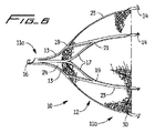
先ず最初に図1、図2、及び図3を参照すると、これらの図には、挿入するための低プロファイル折り畳み形状の閉塞デバイスが示してあり、図4は、拡張配置形状の閉塞デバイスを示す。閉塞デバイス10は、固定構成要素(部材)即ち保持構成要素(部材)12を含む。固定部材12は、以下に説明するように、固定部材12を卵管内に移動しないように保持するため、卵管壁と係合するための係合フック14を有する。メッシュは、その場で固定部材12内に前進させることができ、又は別の態様では、送出位置の固定部材12に位置決めした後、卵管内に配置するため、固定部材12とともに前進できる。閉塞デバイス10は、好ましくは、レーザーで切断したチューブ即ちレーザーカットチューブから形成されるが、この他のデバイス形成方法も考えられる。明瞭化を図るため、図1乃至図4にはメッシュは示してない。
Reference is first made to FIGS. 1, 2 and 3 which show a low profile folded occlusion device for insertion and FIG. 4 shows an expanded arrangement occlusion device. . The
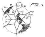
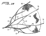
次に、デバイス10を拡張(展開)位置で示す図4乃至図7を参照すると、保持構成要素12は、2004年7月13日に出願された米国特許出願第10/899,429号(以下、’429出願と呼ぶ)に開示された脈管フィルタに関して詳細に説明されているように、ストラットを持つベル型デバイスの形状を備えている。出典を明示することにより、この出願に開示された全ての内容は本明細書の開示の一部とされる。デバイスは、基端11a及び先端11bを有する。固定部材12は、好ましくは、図4に示すオーステナイト形状記憶位置を持つニチノール等の形状記憶合金で形成されており、複数のストラット13が基端11aの頂部18から延びており、先端11bのところで係合フック即ち壁保持フック14で終端する。この実施例では、6個のストラットが設けられているが、ストラットの数を変えてもよい。デバイス10をスネア又は他のデバイスで掴み、所望であれば取り外すことができるように、回収フック16が近位端11aに位置決めされている。ストラット13は、隣接したストラットを相互連結するストラット17によって相互連結されていてもよい。更に詳細には、ストラット13は、好ましくは、領域19のところで、互いから遠ざかる方向に角度をなした二つの連結ストラット17に分かれており、次いで、領域21のところで接合し、フック14で終端する延長ストラット部分23を形成する。相互連結ストラット17はデバイスを補剛し、保持を高め、半径方向力を増大する。これらのストラットにより、展開を更に対称に且つ均等にする。フックは、デバイス10の位置を維持するため、卵管の壁と係合するように形成されている。かくして、ストラットは、好ましくは末広がりになっており、先端開口部及びストラット間空間を形成する。明瞭化を図るため、添付図面において、同じ部分全てに参照番号が付してあるわけではない。ニチノール又は形状記憶合金以外の材料も考えられるということは理解されるべきである。
Referring now to FIGS. 4-7 showing the
フック14は、好ましくは、ストラットから実質的に垂直方向に延びており、好ましくは、フックが平面の外に曲がるようにストラットに捩じり力を加えることによって形成される。好ましくは、第1フック組は第2フック組よりも大きい。好ましくは、レーザーカットチューブに形成されたとき、大きい方のフックは、二つの隣接したストラットの横方向寸法と等価の領域を占有するように形成される。好ましくは、6個のストラットを使用する実施例では、三つの比較的小さいフック及び三つの比較的大きいフックが交互に配置されて設けられる。比較的小さいフックは、好ましくは、挿入のために折り畳んだ場合のフィルタの折り畳みプロファイル(横方向寸法)を最少にするため、’429出願のフィルタフックで行われたのと同様に、互いに関して軸線方向に間隔が隔てられており、比較的大きいフックに関して軸線方向内方にある。嵌入チップ14a(図3参照)は、好ましくは、デバイス10の近位端11aに向いて尖っており、組織に嵌入して閉塞デバイスを保持する。
The
各フック14は一連の歯14cを備えている。これらの歯は、卵管の壁と夫々係合し、デバイス10が動かないようにする追加の保持を提供する。フック14を越えて延びるヒール14dが設けられている。ヒールは、閉塞デバイスが卵管の壁を越えないようにするストップとして機能する。小さい方のフックのヒール14dの角度は、大きい方のフックにおける角度よりも小さく、フックが図3に示すように入れ子になるための余地を提供する。明瞭化を図るため、全てのフックに参照番号が付してあるわけではない。
Each
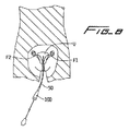
固定(保持)部材12は、図3に示すように、送出用カテーテル又はシース50内で、実質的に直線状の比較的柔らかいマルテンサイト形状に維持される。好ましくは、小さい方のフックは、大きい方のフック内に入れ子になっている。送出中、ストラット13をこのマルテンサイト状態に維持し、カテーテル50の遠位端部分54(図3参照)にある遠位開口部52から出し易くするため、低温の生理食塩水を注入する。ストラット13が送出シース(チューブ)50を出るとき、これらのストラットは体温によって温められ、図4乃至図7に示す記憶された位置に向かって移動する。
The securing (holding)
図8乃至図11、及び図14に示すように、デバイス10は、好ましくは、送出用カテーテル50内で、子宮を通して卵管に挿入される。この実施例では、ストラット開口部が先端方向に向くように位置決めされる。卵管内に配置されたとき、フック14が卵管の壁と係合し、デバイスを保持する。
As shown in FIGS. 8-11 and 14, the
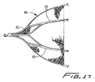
図1乃至図7の実施例のデバイス10は、メッシュ材料が保持部材12内に位置決めされており、このメッシュ材料が保持部材12のほぼ全領域を満たす。近位端に小さな隙間24が残っていてもよい(例えば、図6参照)。しかしながら、変形例では、隙間は、例えば、図17に示すように、ストラット間の領域の大部分をメッシュが満たすようにメッシュで満たされる。この場合、メッシュ62が保持部材60のストラット63間のほぼ全空間を満たす。これ以外は、図1の保持部材12と同じである。メッシュは、好ましくは、卵子が卵巣から卵管を通して移動しないように効果的にブロックする上で十分に小さな空間を提供するため、密に織製した材料の形態である。
The
メッシュは、折り畳み状態でメッシュが保持部材12内に収容されており且つ圧縮されるように保持部材12内に送出される。送出後、保持部材12の空間内で、即ちストラット間の空間内で拡張する。
The mesh is delivered into the holding
変形例では、先ず最初に保持部材12を卵管内に配置した後、所定の場所にある状態でメッシュをデバイスの遠位端11bの開口部を通してストラット13間の空間内に送出する。この現場送出は、デバイス10が図11の実施例とは逆の配向で埋め込まれる実施例で、即ち遠位端11bが近位端11aよりも子宮に近いようにストラット間の開口部が他の方向に面する実施例で行うことができる。
In a variant, the retaining
変形例では、ストラット間の空間を満たすメッシュの代わりに、メッシュは、狭幅のストリップの形態であってもよい。この実施例のメッシュは、図15及び図16に示すように、スクリーン型ブロック部材として機能し、実質的に円形である。固定(保持)部材72は、この他の点については図1の固定部材12と同じである。例えば、ストラット73は、領域79のところで相互連結ストラット77に分かれ、領域81のところで接合し、係合フック74で終端する。メッシュのストリップ85は、好ましくは、フック74と干渉しないように、フック74の僅かに近位側に、例えば、ストラットが捩じれて平面の外に出る領域に位置決めされる。しかしながら、メッシュは、卵管を閉塞するためのカバー又はブロック部材として機能する限り、ストラットに沿ったこの他の位置に配置されていてもよい。薄いメッシュストリップが示してあるけれども、この他の大きさのブロックストリップを設けてもよい。メッシュは、ストラットの内面に取り付けられた状態で示してあるけれども、別の態様では、外面に取り付けられていてもよい。ストラットのうちの一つ又はそれ以上に取り付けられていてもよい。
In a variant, instead of a mesh filling the space between the struts, the mesh may be in the form of a narrow strip. As shown in FIGS. 15 and 16, the mesh of this embodiment functions as a screen-type block member and is substantially circular. The fixing (holding)
上述のように、係合フック14が遠位方向を向くように挿入した状態で保持部材を示すが、保持部材は、逆方向に配向されていてもよいと考えられる。この態様(図示せず)では、メッシュを保持部材とともに挿入してもよいし、又は別の態様では、所望であれば、ストラット間の先端開口部内にその場で送出してもよい。
As described above, the holding member is shown in a state where the
図18の変形例では、メッシュ92は、保持部材90の外側に配置されている。この他の全ての点に関し、保持部材90は、固定部材12と同じである。この実施例では、メッシュ92は外領域に配置されており、ストラット及び頂部領域の外面を覆っており、配置されたときにストラットと卵管との間に配置される。かくして、メッシュは、卵子がスリーブ又はネット状デバイス内に捕捉されたとき、卵子が通過しないようにするスリーブとして機能する。
In the modification of FIG. 18, the
上述の実施例のメッシュは、結合、クランプ止め、又は縫合等の様々な方法によって保持部材に取り付けることができる。 The mesh of the above-described embodiments can be attached to the holding member by various methods such as bonding, clamping, or suturing.
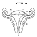
次に、卵管を閉塞するための本発明の閉塞デバイスの配置方法を、メッシュが固定部材と関連して送出される図5のデバイスを例示する図8乃至図14を参照して説明する(この他の実施例は、同様の方法で挿入される)。送出用カテーテル50を、導入器シース100を通して、膣及び頸部を通って子宮U内に挿入する。次いで、送出用カテーテル50を卵管F1内に前進する。挿入を行うため、保持部材12(及びメッシュ)は折り畳み状態にある。
Next, a method of placing the occlusion device of the present invention for occluding the oviduct will be described with reference to FIGS. 8 to 14 illustrating the device of FIG. 5 in which the mesh is delivered in association with a securing member ( Other embodiments are inserted in a similar manner). A
プッシャ(図示せず)を遠位方向に前進し、閉塞デバイス10をカテーテル50から前進する。デバイス10のストラットが露呈されたとき、これらのストラットは体温によって温められ、図11に示す形状記憶展開状態に向かって戻り、卵管の壁W1と係合する。ストラットが、記憶された状態までどの程度戻るのかは、卵管の大きさで決まる。次いで、カテーテル50を子宮内に引っ込め、卵管F2に挿入する(図12参照)(又は他のカテーテルを使用する。別の閉塞デバイス10がカテーテル50から露呈され、その結果、ストラットは拡張位置に移動し、図13に示すように卵管F2の壁W2と係合する。拡張させたメッシュは、卵子が卵管を通って移動しないようにブロックする。
A pusher (not shown) is advanced distally and the
わかるように、卵管の閉鎖について説明したが、閉鎖デバイスは、身体の他の領域で使用できる。 As can be seen, the oviduct closure has been described, but the closure device can be used in other areas of the body.
保持部材の内側又は外側の材料は、非孔質であってもよいし多孔質であってもよい。別の態様では、心膜、SIS、PET、PTFE等で形成されていてもよい。 The material inside or outside the holding member may be non-porous or porous. In another aspect, it may be formed of pericardium, SIS, PET, PTFE or the like.
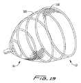
図19の変形例では、巻いたワイヤ100がメッシュ110用の支持部材を提供する。ワイヤは、図示のように、実質的に円錐形のメッシュを有し、領域112での直径(横方向寸法)は領域114の直径(横方向寸法)よりも大きい。メッシュ110は、図示のように外面に設けられている。別の実施例では、メッシュは内側に位置決めされていてもよく、開口部に亘って張ったメッシュストリップであってもよい。ワイヤは、卵管の壁に対する外方への半径方向力に加えて保持を高めるため、フック、返し、又は他の表面を備えていてもよい。
In the variation of FIG. 19, the
以上の説明は多くの特徴を含むけれども、これらの特徴は、開示の範囲を限定するものと解釈されるべきではなく、本発明の好ましい実施例の単なる例示である解釈されるべきである。例えば、卵子が卵管を通って移動しないようにブロックするように機能するため、他の材料が保持部材に含まれていてもよいし取り付けられていてもよい。多くの他の可能な変更が、本願に添付された特許請求の範囲に定義された開示の範囲及び精神に含まれるということは当業者には理解されよう。 Although the foregoing description includes many features, these features should not be construed as limiting the scope of the disclosure, but merely as exemplifications of preferred embodiments of the invention. For example, other materials may be included in or attached to the holding member to function to block the ovum from moving through the fallopian tube. Those skilled in the art will recognize that many other possible modifications are within the scope and spirit of the disclosure as defined in the claims appended hereto.
10 閉塞デバイス
11a 近位端
11b 遠位端
12 固定(保持)部材
13 ストラット
14 係合フック
14a 嵌入チップ
14c 歯
14d ヒール
17 相互連結ストラット
18 頂部
19 領域
23 延長ストラット
50 送出用カテーテル
52 遠位開口部
54 遠位端部分
DESCRIPTION OF
Claims (19)
保持部材と、この保持部材によって支持されたメッシュ材料とを含み、
前記保持部材は、送出するための第1低プロファイル形状と、卵管内に配置するための第2拡張形状とを有し、
前記メッシュ材料は、卵管を通る卵子の通過をブロックする形状を有し、
前記保持部材は、前記保持部材を卵管に固定する少なくとも一つの卵管係合部材を有する、デバイス。 In a device for occluding an oviduct,
A holding member and a mesh material supported by the holding member;
The holding member has a first low profile shape for delivery and a second expanded shape for placement in the fallopian tube,
The mesh material has a shape that blocks passage of the ovum through the fallopian tube,
The holding member has at least one fallopian tube engaging member that fixes the hold member to the fallopian tube.
前記メッシュは前記保持部材の外面に取り付けられている、デバイス。 The device of claim 1, wherein
The device, wherein the mesh is attached to an outer surface of the holding member.
前記メッシュは前記保持部材内に位置決めされる、デバイス。 The device of claim 1, wherein
The device, wherein the mesh is positioned within the retaining member.
前記保持部材は、空間を間に形成する複数のストラットを有し、前記メッシュは前記空間の大部分の領域を満たす、デバイス。 The device of claim 1, wherein
The holding member has a plurality of struts forming a space therebetween, and the mesh fills a large area of the space.
前記メッシュは、前記保持部材に取り付けられた材料ストリップであり、前記保持部材の開口部に亘って延びている、デバイス。 The device of claim 1, wherein
The device, wherein the mesh is a strip of material attached to the holding member and extends across an opening in the holding member.
前記メッシュは、前記卵管係合部材と隣接した領域に位置決めされている、デバイス。 The device of claim 5, wherein
The device, wherein the mesh is positioned in a region adjacent to the fallopian tube engaging member.
前記保持部材は、空間を間に形成する複数のストラットを有し、前記メッシュは、前記空間に亘って延びるように位置決めされる、デバイス。 The device of claim 1, wherein
The holding member has a plurality of struts forming a space therebetween, and the mesh is positioned so as to extend over the space.
前記卵管係合部材は複数の歯を含む、デバイス。 The device of claim 1, wherein
The device wherein the fallopian tube engaging member includes a plurality of teeth.
前記保持部材は複数のストラットを有し、これらのストラットは前記卵管係合部材で終端する、デバイス。 The device of claim 1, wherein
The holding member has a plurality of struts, and the struts terminate at the fallopian tube engaging member.
前記保持部材は、巻いたワイヤを含む、デバイス。 The device of claim 1, wherein
The device, wherein the holding member comprises a wound wire.
前記保持部材は、形状記憶材料で形成されている、デバイス。 The device of claim 1, wherein
The holding member is a device formed of a shape memory material.
一連のストラットを形成するようにレーザーでカットしたチューブを含み、前記チューブは、送出するための第1低プロファイル形状と、配置するための第2形状とを有し、
前記第2形状では、前記チューブは拡張形状を有し、前記ストラットは、これらのストラットの遠位領域の方が寸法が大きくなるように外方に延びており、前記ストラットは、その間に空間を形成し、メッシュ材料が前記ストラットによって支持されており、卵子が卵管を通過しないようにブロックするブロック部材を提供する。 In a device for occluding an oviduct,
A tube cut with a laser to form a series of struts, the tube having a first low profile shape for delivery and a second shape for placement;
In the second shape, the tubes have an expanded shape, and the struts extend outward so that the distal regions of these struts are larger in size, the struts having a space therebetween. A block member is provided that blocks and prevents the ovum from passing through the fallopian tube, with the mesh material supported by the struts.
前記メッシュ材料は、前記ストラット間の空間の大部分の領域を満たす、デバイス。 The device of claim 12, wherein
The mesh material fills a large area of the space between the struts.
前記メッシュ材料は、前記ストラットのうちの一つ又はそれ以上に取り付けられた狭幅のストリップの形態である、デバイス。 The device of claim 12, wherein
The device, wherein the mesh material is in the form of a narrow strip attached to one or more of the struts.
前記メッシュ材料は前記ストラットの外面に取り付けられている、デバイス。 The device of claim 12, wherein
The device, wherein the mesh material is attached to an outer surface of the strut.
前記メッシュは前記デバイスの近位領域を横切って延びる、デバイス。 The device of claim 15, wherein
The device, wherein the mesh extends across a proximal region of the device.
前記保持部材は形状記憶材料で形成されている、デバイス。 The device of claim 12, wherein
The holding member is made of a shape memory material.
縮径プロファイル状態の複数のストラットを持つ保持部材を収容したシースを卵管に挿入する工程と、
前記保持部材を前記シースから出し、前記保持部材が拡張することにより卵管の壁と係合できるようにする工程と、
次いで、メッシュ材料を、前記複数のストラット間の空間に挿入する工程と、
前記シースを引き出し、卵子の移動をブロックするため、前記メッシュ材料が前記ストラット内の空間を満たすように、前記保持部材を卵管に残す工程とを含む、方法。 In a method for occluding an oviduct,
Inserting a sheath containing a holding member having a plurality of struts in a reduced diameter profile state into an oviduct;
Removing the holding member from the sheath and allowing the holding member to expand to engage the wall of the fallopian tube;
Then inserting a mesh material into the space between the plurality of struts;
Leaving the retaining member in the oviduct so that the mesh material fills the space in the struts to withdraw the sheath and block movement of the ovum.
前記保持部材は、複数の形状記憶ストラットを有し、前記保持部材を出す前記工程により、前記ストラットを形状記憶位置に向かって移動できる、方法。 The method of claim 18, wherein
The method, wherein the holding member has a plurality of shape memory struts and the strut can be moved toward a shape memory position by the step of taking out the holding members.
Applications Claiming Priority (2)
| Application Number | Priority Date | Filing Date | Title |
|---|---|---|---|
| US93240507P | 2007-05-31 | 2007-05-31 | |
| PCT/US2008/006000 WO2008153653A1 (en) | 2007-05-31 | 2008-05-09 | Fallopian tube occlusion device |
Publications (2)
| Publication Number | Publication Date |
|---|---|
| JP2010532180A true JP2010532180A (en) | 2010-10-07 |
| JP2010532180A5 JP2010532180A5 (en) | 2010-11-18 |
Family
ID=39671951
Family Applications (1)
| Application Number | Title | Priority Date | Filing Date |
|---|---|---|---|
| JP2010510283A Pending JP2010532180A (en) | 2007-05-31 | 2008-05-09 | Fallopian tube occlusion device |
Country Status (6)
| Country | Link |
|---|---|
| US (2) | US7992565B2 (en) |
| EP (1) | EP2152212A1 (en) |
| JP (1) | JP2010532180A (en) |
| AU (1) | AU2008262587B2 (en) |
| CA (1) | CA2687777A1 (en) |
| WO (1) | WO2008153653A1 (en) |
Cited By (11)
| Publication number | Priority date | Publication date | Assignee | Title |
|---|---|---|---|---|
| US8984733B2 (en) | 2013-02-05 | 2015-03-24 | Artventive Medical Group, Inc. | Bodily lumen occlusion |
| US9017351B2 (en) | 2010-06-29 | 2015-04-28 | Artventive Medical Group, Inc. | Reducing flow through a tubular structure |
| US9095344B2 (en) | 2013-02-05 | 2015-08-04 | Artventive Medical Group, Inc. | Methods and apparatuses for blood vessel occlusion |
| US9149277B2 (en) | 2010-10-18 | 2015-10-06 | Artventive Medical Group, Inc. | Expandable device delivery |
| US9247942B2 (en) | 2010-06-29 | 2016-02-02 | Artventive Medical Group, Inc. | Reversible tubal contraceptive device |
| US9636116B2 (en) | 2013-06-14 | 2017-05-02 | Artventive Medical Group, Inc. | Implantable luminal devices |
| US9737306B2 (en) | 2013-06-14 | 2017-08-22 | Artventive Medical Group, Inc. | Implantable luminal devices |
| US9737308B2 (en) | 2013-06-14 | 2017-08-22 | Artventive Medical Group, Inc. | Catheter-assisted tumor treatment |
| US10149968B2 (en) | 2013-06-14 | 2018-12-11 | Artventive Medical Group, Inc. | Catheter-assisted tumor treatment |
| US10363043B2 (en) | 2014-05-01 | 2019-07-30 | Artventive Medical Group, Inc. | Treatment of incompetent vessels |
| US10813644B2 (en) | 2016-04-01 | 2020-10-27 | Artventive Medical Group, Inc. | Occlusive implant and delivery system |
Families Citing this family (16)
| Publication number | Priority date | Publication date | Assignee | Title |
|---|---|---|---|---|
| US8181653B2 (en) | 2005-02-15 | 2012-05-22 | Yale University | Intrauterine fallopian tube occlusion device |
| EP1848386B1 (en) * | 2005-02-15 | 2018-05-09 | Yale University | Intrauterine fallopian tube occlusion device |
| US8662081B2 (en) | 2005-02-15 | 2014-03-04 | Yale University | Intrauterine device |
| US20090062838A1 (en) * | 2007-08-27 | 2009-03-05 | Cook Incorporated | Spider device with occlusive barrier |
| US8734483B2 (en) * | 2007-08-27 | 2014-05-27 | Cook Medical Technologies Llc | Spider PFO closure device |
| US9320525B2 (en) * | 2008-12-03 | 2016-04-26 | Boston Scientific Scimed, Inc. | Occlusion stent |
| US8360065B2 (en) * | 2009-05-21 | 2013-01-29 | Boston Scientific Scimed, Inc. | Occlusion of fallopian tubes in a vertebrate subject |
| CN101779995B (en) * | 2010-02-26 | 2011-11-09 | 长沙希利奇生物科技有限公司 | Sterilization stopper |
| US9180039B2 (en) | 2010-08-16 | 2015-11-10 | Yale University | Intrauterine device |
| US10342548B2 (en) * | 2012-01-13 | 2019-07-09 | W. L. Gore & Associates, Inc. | Occlusion devices and methods of their manufacture and use |
| WO2013119573A1 (en) * | 2012-02-06 | 2013-08-15 | Artventive Medical Group, Inc. | Reversible tubal contraceptive device |
| US9011481B2 (en) * | 2012-12-30 | 2015-04-21 | Cook Medical Technologies Llc | Vascular occlusion device having a jelly fish |
| US9005122B2 (en) | 2013-02-15 | 2015-04-14 | Pneumoflex Systems, Llc | Device with passive valve to block emesis and/or reflux and associated system and method |
| US9005123B2 (en) | 2013-02-15 | 2015-04-14 | Pneumoflex Systems, Llc | Device with active valve to block emesis and reflux blockage device and associated system and method |
| US9005124B2 (en) | 2013-02-15 | 2015-04-14 | Pneumoflex Systems, Llc | Device to block emesis and reflux and associated system and method |
| CN105107079B (en) * | 2015-06-25 | 2018-06-01 | 南通伊凯医疗器械有限公司 | A kind of infertile treatment closure plug |
Citations (3)
| Publication number | Priority date | Publication date | Assignee | Title |
|---|---|---|---|---|
| JP2002506359A (en) * | 1996-12-18 | 2002-02-26 | オービオン・インコーポレイテッド | Contraceptive system and method of use |
| JP2003520056A (en) * | 1998-07-08 | 2003-07-02 | オービオン・インコーポレイテッド | Closure device and method of use |
| JP2006500187A (en) * | 2002-09-19 | 2006-01-05 | ペトルス・ベッセリンク | Vascular filter with improved strength and flexibility |
Family Cites Families (55)
| Publication number | Priority date | Publication date | Assignee | Title |
|---|---|---|---|---|
| US3744492A (en) * | 1971-04-07 | 1973-07-10 | S Leibinsohn | Drip chamber |
| ZA793232B (en) * | 1978-07-03 | 1980-09-24 | Smiths Industries Ltd | Connectors |
| FR2567405B1 (en) | 1984-07-12 | 1988-08-12 | Lefebvre Jean Marie | MEDICAL FILTER |
| US4832055A (en) * | 1988-07-08 | 1989-05-23 | Palestrant Aubrey M | Mechanically locking blood clot filter |
| US5059205A (en) * | 1989-09-07 | 1991-10-22 | Boston Scientific Corporation | Percutaneous anti-migration vena cava filter |
| US6059825A (en) * | 1992-03-05 | 2000-05-09 | Angiodynamics, Inc. | Clot filter |
| EP0746236B1 (en) * | 1993-10-01 | 2003-08-20 | Boston Scientific Corporation | Improved vena cava filter |
| EP1695673A3 (en) * | 1994-07-08 | 2009-07-08 | ev3 Inc. | Intravascular filtering device |
| US5709704A (en) * | 1994-11-30 | 1998-01-20 | Boston Scientific Corporation | Blood clot filtering |
| EP1707233A3 (en) | 1996-02-02 | 2006-12-20 | Medtronic Vascular, Inc. | Apparatus for blocking flow through blood vessels |
| US5885258A (en) * | 1996-02-23 | 1999-03-23 | Memory Medical Systems, Inc. | Medical instrument with slotted memory metal tube |
| US7128073B1 (en) | 1998-11-06 | 2006-10-31 | Ev3 Endovascular, Inc. | Method and device for left atrial appendage occlusion |
| US6152144A (en) * | 1998-11-06 | 2000-11-28 | Appriva Medical, Inc. | Method and device for left atrial appendage occlusion |
| US7044134B2 (en) | 1999-11-08 | 2006-05-16 | Ev3 Sunnyvale, Inc | Method of implanting a device in the left atrial appendage |
| US7713282B2 (en) | 1998-11-06 | 2010-05-11 | Atritech, Inc. | Detachable atrial appendage occlusion balloon |
| US6355051B1 (en) * | 1999-03-04 | 2002-03-12 | Bioguide Consulting, Inc. | Guidewire filter device |
| US6368338B1 (en) | 1999-03-05 | 2002-04-09 | Board Of Regents, The University Of Texas | Occlusion method and apparatus |
| US6436120B1 (en) * | 1999-04-20 | 2002-08-20 | Allen J. Meglin | Vena cava filter |
| US6235044B1 (en) * | 1999-08-04 | 2001-05-22 | Scimed Life Systems, Inc. | Percutaneous catheter and guidewire for filtering during ablation of mycardial or vascular tissue |
| US6231561B1 (en) | 1999-09-20 | 2001-05-15 | Appriva Medical, Inc. | Method and apparatus for closing a body lumen |
| US6689150B1 (en) * | 1999-10-27 | 2004-02-10 | Atritech, Inc. | Filter apparatus for ostium of left atrial appendage |
| US6652555B1 (en) * | 1999-10-27 | 2003-11-25 | Atritech, Inc. | Barrier device for covering the ostium of left atrial appendage |
| US6551303B1 (en) * | 1999-10-27 | 2003-04-22 | Atritech, Inc. | Barrier device for ostium of left atrial appendage |
| US6994092B2 (en) | 1999-11-08 | 2006-02-07 | Ev3 Sunnyvale, Inc. | Device for containing embolic material in the LAA having a plurality of tissue retention structures |
| US6660021B1 (en) * | 1999-12-23 | 2003-12-09 | Advanced Cardiovascular Systems, Inc. | Intravascular device and system |
| US6293906B1 (en) | 2000-01-14 | 2001-09-25 | Acorn Cardiovascular, Inc. | Delivery of cardiac constraint jacket |
| US7169164B2 (en) | 2000-09-21 | 2007-01-30 | Atritech, Inc. | Apparatus for implanting devices in atrial appendages |
| US6689151B2 (en) | 2001-01-25 | 2004-02-10 | Scimed Life Systems, Inc. | Variable wall thickness for delivery sheath housing |
| US6506205B2 (en) * | 2001-02-20 | 2003-01-14 | Mark Goldberg | Blood clot filtering system |
| US6941169B2 (en) * | 2001-06-04 | 2005-09-06 | Albert Einstein Healthcare Network | Cardiac stimulating apparatus having a blood clot filter and atrial pacer |
| JP4294470B2 (en) * | 2001-06-14 | 2009-07-15 | クック インコーポレイテッド | Intravascular filter |
| US6599307B1 (en) * | 2001-06-29 | 2003-07-29 | Advanced Cardiovascular Systems, Inc. | Filter device for embolic protection systems |
| EP1277448B1 (en) * | 2001-07-13 | 2006-06-07 | B. Braun Medical SAS | System of vascular protection and angioplasty device |
| US7097651B2 (en) * | 2001-09-06 | 2006-08-29 | Advanced Cardiovascular Systems, Inc. | Embolic protection basket |
| US6811560B2 (en) * | 2001-09-20 | 2004-11-02 | Cordis Neurovascular, Inc. | Stent aneurysm embolization method and device |
| US6890340B2 (en) * | 2001-11-29 | 2005-05-10 | Medtronic Vascular, Inc. | Apparatus for temporary intraluminal protection |
| US6958074B2 (en) * | 2002-01-07 | 2005-10-25 | Cordis Corporation | Releasable and retrievable vascular filter system |
| WO2003063732A2 (en) | 2002-01-25 | 2003-08-07 | Atritech, Inc. | Atrial appendage blood filtration systems |
| US6989021B2 (en) * | 2002-10-31 | 2006-01-24 | Cordis Corporation | Retrievable medical filter |
| AU2003285248A1 (en) | 2002-11-29 | 2004-06-23 | Vascular Interventional Technologies Inc. | Embolus blood clot filter |
| US7316708B2 (en) * | 2002-12-05 | 2008-01-08 | Cardiac Dimensions, Inc. | Medical device delivery system |
| US20040111111A1 (en) | 2002-12-10 | 2004-06-10 | Scimed Life Systems, Inc. | Intravascular filter membrane with shape memory |
| US7220271B2 (en) | 2003-01-30 | 2007-05-22 | Ev3 Inc. | Embolic filters having multiple layers and controlled pore size |
| US7896898B2 (en) | 2003-07-30 | 2011-03-01 | Boston Scientific Scimed, Inc. | Self-centering blood clot filter |
| CA2538480A1 (en) | 2003-09-12 | 2005-04-21 | Nmt Medical, Inc. | Device and methods for preventing formation of thrombi in the left atrial appendage |
| US6972025B2 (en) * | 2003-11-18 | 2005-12-06 | Scimed Life Systems, Inc. | Intravascular filter with bioabsorbable centering element |
| US7976562B2 (en) | 2004-01-22 | 2011-07-12 | Rex Medical, L.P. | Method of removing a vein filter |
| US7704266B2 (en) | 2004-01-22 | 2010-04-27 | Rex Medical, L.P. | Vein filter |
| US7338512B2 (en) | 2004-01-22 | 2008-03-04 | Rex Medical, L.P. | Vein filter |
| CA2555009C (en) | 2004-02-02 | 2012-08-07 | Ams Research Corporation | Contraceptive with permeable and impermeable components |
| US20050256532A1 (en) | 2004-05-12 | 2005-11-17 | Asha Nayak | Cardiovascular defect patch device and method |
| WO2006036457A2 (en) | 2004-09-27 | 2006-04-06 | Rex Medical, L.P. | Vein filter |
| US7279000B2 (en) * | 2004-09-29 | 2007-10-09 | Angiodynamics Inc | Permanent blood clot filter with capability of being retrieved |
| US7850708B2 (en) | 2005-06-20 | 2010-12-14 | Cook Incorporated | Embolic protection device having a reticulated body with staggered struts |
| US20070100372A1 (en) * | 2005-11-02 | 2007-05-03 | Cook Incorporated | Embolic protection device having a filter |
-
2008
- 2008-05-09 EP EP08754329A patent/EP2152212A1/en not_active Withdrawn
- 2008-05-09 US US12/151,953 patent/US7992565B2/en active Active
- 2008-05-09 AU AU2008262587A patent/AU2008262587B2/en not_active Ceased
- 2008-05-09 WO PCT/US2008/006000 patent/WO2008153653A1/en active Application Filing
- 2008-05-09 JP JP2010510283A patent/JP2010532180A/en active Pending
- 2008-05-09 CA CA002687777A patent/CA2687777A1/en not_active Abandoned
-
2011
- 2011-06-30 US US13/173,418 patent/US20110259341A1/en not_active Abandoned
Patent Citations (3)
| Publication number | Priority date | Publication date | Assignee | Title |
|---|---|---|---|---|
| JP2002506359A (en) * | 1996-12-18 | 2002-02-26 | オービオン・インコーポレイテッド | Contraceptive system and method of use |
| JP2003520056A (en) * | 1998-07-08 | 2003-07-02 | オービオン・インコーポレイテッド | Closure device and method of use |
| JP2006500187A (en) * | 2002-09-19 | 2006-01-05 | ペトルス・ベッセリンク | Vascular filter with improved strength and flexibility |
Cited By (16)
| Publication number | Priority date | Publication date | Assignee | Title |
|---|---|---|---|---|
| US9017351B2 (en) | 2010-06-29 | 2015-04-28 | Artventive Medical Group, Inc. | Reducing flow through a tubular structure |
| US9451965B2 (en) | 2010-06-29 | 2016-09-27 | Artventive Medical Group, Inc. | Reducing flow through a tubular structure |
| US9247942B2 (en) | 2010-06-29 | 2016-02-02 | Artventive Medical Group, Inc. | Reversible tubal contraceptive device |
| US9149277B2 (en) | 2010-10-18 | 2015-10-06 | Artventive Medical Group, Inc. | Expandable device delivery |
| US9737307B2 (en) | 2013-02-05 | 2017-08-22 | Artventive Medical Group, Inc. | Blood vessel occlusion |
| US9107669B2 (en) | 2013-02-05 | 2015-08-18 | Artventive Medical Group, Inc. | Blood vessel occlusion |
| US9095344B2 (en) | 2013-02-05 | 2015-08-04 | Artventive Medical Group, Inc. | Methods and apparatuses for blood vessel occlusion |
| US8984733B2 (en) | 2013-02-05 | 2015-03-24 | Artventive Medical Group, Inc. | Bodily lumen occlusion |
| US9636116B2 (en) | 2013-06-14 | 2017-05-02 | Artventive Medical Group, Inc. | Implantable luminal devices |
| US9737306B2 (en) | 2013-06-14 | 2017-08-22 | Artventive Medical Group, Inc. | Implantable luminal devices |
| US9737308B2 (en) | 2013-06-14 | 2017-08-22 | Artventive Medical Group, Inc. | Catheter-assisted tumor treatment |
| US10149968B2 (en) | 2013-06-14 | 2018-12-11 | Artventive Medical Group, Inc. | Catheter-assisted tumor treatment |
| US10441290B2 (en) | 2013-06-14 | 2019-10-15 | Artventive Medical Group, Inc. | Implantable luminal devices |
| US10363043B2 (en) | 2014-05-01 | 2019-07-30 | Artventive Medical Group, Inc. | Treatment of incompetent vessels |
| US11224438B2 (en) | 2014-05-01 | 2022-01-18 | Artventive Medical Group, Inc. | Treatment of incompetent vessels |
| US10813644B2 (en) | 2016-04-01 | 2020-10-27 | Artventive Medical Group, Inc. | Occlusive implant and delivery system |
Also Published As
| Publication number | Publication date |
|---|---|
| EP2152212A1 (en) | 2010-02-17 |
| US7992565B2 (en) | 2011-08-09 |
| WO2008153653A1 (en) | 2008-12-18 |
| AU2008262587B2 (en) | 2013-05-23 |
| US20110259341A1 (en) | 2011-10-27 |
| CA2687777A1 (en) | 2008-12-18 |
| US20080302368A1 (en) | 2008-12-11 |
| AU2008262587A1 (en) | 2008-12-18 |
Similar Documents
| Publication | Publication Date | Title |
|---|---|---|
| JP2010532180A (en) | Fallopian tube occlusion device | |
| US9149279B2 (en) | Occluding device | |
| JP5225072B2 (en) | Left atrial appendage obturator | |
| JP2010527742A (en) | Left atrial appendage closure device | |
| US20160095603A1 (en) | Device for preventing clot migraton from left atrial appendage | |
| WO2010068589A1 (en) | Retractable tacking device | |
| US20180049731A1 (en) | Closing device for tissue openings | |
| EP1788991A1 (en) | Reversible vessel seal | |
| US8695605B2 (en) | Fallopian tube occlusion device | |
| US9585786B2 (en) | Reversible contraceptive implant system and method | |
| US9320525B2 (en) | Occlusion stent | |
| AU2017268717A1 (en) | Gastrointestinal barrier implant and method of use, surgical anchor, and delivery tool for surgical anchors |
Legal Events
| Date | Code | Title | Description |
|---|---|---|---|
| A621 | Written request for application examination |
Free format text: JAPANESE INTERMEDIATE CODE: A621 Effective date: 20110421 |
|
| A977 | Report on retrieval |
Free format text: JAPANESE INTERMEDIATE CODE: A971007 Effective date: 20121115 |
|
| A131 | Notification of reasons for refusal |
Free format text: JAPANESE INTERMEDIATE CODE: A131 Effective date: 20121126 |
|
| A521 | Written amendment |
Free format text: JAPANESE INTERMEDIATE CODE: A523 Effective date: 20130226 |
|
| A02 | Decision of refusal |
Free format text: JAPANESE INTERMEDIATE CODE: A02 Effective date: 20130401 |
|
| A521 | Written amendment |
Free format text: JAPANESE INTERMEDIATE CODE: A523 Effective date: 20130801 |
|
| A911 | Transfer to examiner for re-examination before appeal (zenchi) |
Free format text: JAPANESE INTERMEDIATE CODE: A911 Effective date: 20130809 |