JP2010523948A - Method for measuring roundness of round wire - Google Patents
Method for measuring roundness of round wire Download PDFInfo
- Publication number
- JP2010523948A JP2010523948A JP2010501423A JP2010501423A JP2010523948A JP 2010523948 A JP2010523948 A JP 2010523948A JP 2010501423 A JP2010501423 A JP 2010501423A JP 2010501423 A JP2010501423 A JP 2010501423A JP 2010523948 A JP2010523948 A JP 2010523948A
- Authority
- JP
- Japan
- Prior art keywords
- contour
- vectors
- center
- circle
- round wire
- Prior art date
- Legal status (The legal status is an assumption and is not a legal conclusion. Google has not performed a legal analysis and makes no representation as to the accuracy of the status listed.)
- Granted
Links
Images
Classifications
-
- G—PHYSICS
- G01—MEASURING; TESTING
- G01B—MEASURING LENGTH, THICKNESS OR SIMILAR LINEAR DIMENSIONS; MEASURING ANGLES; MEASURING AREAS; MEASURING IRREGULARITIES OF SURFACES OR CONTOURS
- G01B11/00—Measuring arrangements characterised by the use of optical techniques
- G01B11/24—Measuring arrangements characterised by the use of optical techniques for measuring contours or curvatures
- G01B11/2408—Measuring arrangements characterised by the use of optical techniques for measuring contours or curvatures for measuring roundness
-
- G—PHYSICS
- G01—MEASURING; TESTING
- G01B—MEASURING LENGTH, THICKNESS OR SIMILAR LINEAR DIMENSIONS; MEASURING ANGLES; MEASURING AREAS; MEASURING IRREGULARITIES OF SURFACES OR CONTOURS
- G01B11/00—Measuring arrangements characterised by the use of optical techniques
- G01B11/24—Measuring arrangements characterised by the use of optical techniques for measuring contours or curvatures
- G01B11/245—Measuring arrangements characterised by the use of optical techniques for measuring contours or curvatures using a plurality of fixed, simultaneously operating transducers
-
- B—PERFORMING OPERATIONS; TRANSPORTING
- B21—MECHANICAL METAL-WORKING WITHOUT ESSENTIALLY REMOVING MATERIAL; PUNCHING METAL
- B21B—ROLLING OF METAL
- B21B38/00—Methods or devices for measuring, detecting or monitoring specially adapted for metal-rolling mills, e.g. position detection, inspection of the product
- B21B38/04—Methods or devices for measuring, detecting or monitoring specially adapted for metal-rolling mills, e.g. position detection, inspection of the product for measuring thickness, width, diameter or other transverse dimensions of the product
Landscapes
- Physics & Mathematics (AREA)
- General Physics & Mathematics (AREA)
- Length Measuring Devices By Optical Means (AREA)
Abstract
Description
本発明はローラ列の中を長手方向に動く丸線材の真円度測定または形状誤差の測定のための方法に関する。この方法では、それ自体は公知のように、それぞれ感光センサとレーザとを有する少なくとも2つのレーザスキャナを備えた測定装置を用いて、測定される丸線材に接し、この丸線材を囲む多角形を成す少なくとも3つのシャドウエッジが形成および測定され、そこから相応する接線が計算される。 The present invention relates to a method for measuring roundness or shape error of a round wire moving in the longitudinal direction in a roller array. In this method, as is known per se, using a measuring device having at least two laser scanners each having a photosensitive sensor and a laser, a polygon that touches the round wire to be measured and surrounds the round wire is formed. At least three shadow edges are formed and measured, from which the corresponding tangent is calculated.
鉄鋼業では、所望の最終製品を得るために、いわゆる長物が専用ローラ列中で圧延される。これらの長物を圧延してロッドにする場合には、長物はたいてい複数のローラブロック(たいてい3ローラブロック)をもつ3ローラ仕上げ台で最終寸法まで圧延され、冷却床上で冷却される。通常は、それぞれ3つのローラディスクを備えた4つのローラブロックが使用される。なお、ローラディスクの中央平面は隣りのローラブロックからそれぞれ60°だけずれている。この種の棒鋼は円形から偏差して多角形をしていることが多い。主な形状は「3波」または「6波」である。 In the steel industry, so-called long products are rolled in dedicated roller trains to obtain the desired end product. When these long products are rolled into rods, the long products are usually rolled to final dimensions on a three-roller finishing platform with a plurality of roller blocks (usually three roller blocks) and cooled on a cooling bed. Usually, four roller blocks each having three roller disks are used. Note that the central plane of the roller disc is offset by 60 ° from the adjacent roller block. This type of steel bar often has a polygonal shape that deviates from a circular shape. The main shape is “3 waves” or “6 waves”.
この種の多角形棒鋼の直径を機械的なノギスで測定したり、あるいは周を光学的に測定すると、求められたすべての直径が同じ値を有することがありうる。しかし、実際には製品は丸くなく、非円/波状である。この種の製品は「定幅曲線」と呼ばれる。 If the diameter of this type of polygonal bar is measured with a mechanical caliper, or the circumference is measured optically, all the determined diameters can have the same value. In practice, however, the product is not round and non-circular / wavy. This type of product is called a “constant width curve”.
いわゆる定幅曲線誤差を求めるためには、支持角柱を有するノギスが使用されている。周の輪郭の波に応じてさまざまな支持角が推奨される。 In order to obtain a so-called constant-width curve error, a caliper having a supporting prism is used. Different support angles are recommended depending on the contour wave.
真円度の機械的測定とその計算は数十年来関連するDIN規格に、例えばドイツ規格DIN ISO 4291の"Verfahren fuer die Ermittlung der Rundheitabweichung"、DIN ISO 6318の"Rundheitmessung, Begriffe und Kenngroessen fuer die Rundheit"、およびDIN ISO 4292の"Verfahren zum Messen von Rundheitabweichungen, Zweipunkt- und Dreipunkt-Messverfahren"に記載および解説されている。 The mechanical measurement of roundness and its calculation are related to DIN standards that have been relevant for decades, for example the German standard DIN ISO 4291 "Verfahren fuer die Ermittlung der Rundheitabweichung", DIN ISO 6318 "Rundheitmessung, Begriffe und Kenngroessen fuer die Rundheit" And DIN ISO 4292, “Verfahren zum Messen von Rundheitabweichungen, Zweipunkt- und Dreipunkt-Messverfahren”.
ここで話題にしている種類の長物の機械的な真円度測定装置を用いた機械的測定はオフラインで行われなければならない。この測定のためには、精密ターニング装置内にパターンを張らなければならない。回転運動中の輪郭の半径方向の偏差はタッチセンサによって測定される。結果として、そのときそのときの度数に応じた半径をもつ周の輪郭のグラフィック表現が得られる。この周の輪郭の評価は冒頭で述べた関連規格に詳細に記載されている。 The mechanical measurement using the mechanical roundness measuring device of the type of long material discussed here must be performed off-line. For this measurement, a pattern must be placed in the precision turning device. The radial deviation of the contour during the rotational movement is measured by a touch sensor. As a result, a graphic representation of the contour of the circumference having a radius according to the power at that time is obtained. The evaluation of the contour of this circumference is described in detail in the related standards mentioned at the beginning.
測定室内での機械的測定の際に、パターンを回転させることによって周上の無制限の個数の点を求めるようにしてもよい。これに対して、製品が長手方向に輸送される生産ライン中では、局所断面の輪郭を求めることができるように、所望のすべての接線の測定が同時に行われなければならない。したがって、機械的なオンライン測定は不可能である。 When performing mechanical measurement in the measurement chamber, an unlimited number of points on the circumference may be obtained by rotating the pattern. In contrast, in a production line where products are transported in the longitudinal direction, all desired tangent measurements must be made simultaneously so that the profile of the local cross section can be determined. Therefore, mechanical on-line measurement is not possible.
非円度の測定および評価の際の重要な出力パラメータはいわゆる基準円とその中心であり、測定プロセスの以降すべてのステップがこれを基準としている。規格には4つの異なる求め方が記載されている。 An important output parameter in the measurement and evaluation of non-circularity is the so-called reference circle and its center, from which all subsequent steps of the measurement process are based. The standard describes four different ways of obtaining it.
また、機械的測定の他に、非接触測定法も数十年来公知である(例えばDE 39 16 715およびDE 40 37 383 A1)。さらに、例えばJP 56−117107 Aには、測定されるべき長物をレーザ光線を用いて測定ないし走査する輪郭測定方法が記載されている。この刊行物には、例えば、定幅曲線の場合であっても、測定すべき輪郭をもつ物体の外周に第1、第2および第3の接線を当て、これら接線によって定まる円と測定すべき長物の輪郭との差によって輪郭測定を行うことにより、精確な輪郭測定が可能になることが記載されている。なお、接線の接触はレーザ光線ないし投影光線を用いて行われる。 Besides mechanical measurements, non-contact measurement methods have also been known for several decades (eg DE 39 16 715 and DE 40 37 383 A1). Furthermore, for example, JP 56-117107 A describes a contour measuring method for measuring or scanning a long object to be measured using a laser beam. In this publication, for example, even in the case of a constant-width curve, the first, second and third tangent lines are applied to the outer periphery of an object having a contour to be measured, and a circle determined by these tangent lines should be measured. It is described that accurate contour measurement is possible by performing contour measurement based on the difference from the contour of a long object. Note that tangential contact is performed using a laser beam or a projection beam.
また、DE 100 23 172 Aからは、ここで論じている丸物製品ないし丸線材の非円度を測定する方法が公知である。この方法では、それぞれ1つの感光センサと1つのレーザとを有する3つ以上のレーザスキャナから成る測定装置が使用される。丸物製品は、この丸物製品が関連するセンサに1つまたは2つのシャドウエッジを投影するように、それぞれのレーザスキャナからのレーザ光線によって照明される。それぞれのシャドウエッジについて、レーザ光線に平行な直線が計算される。さらに、求められた3つの直線ごとに1つの円が計算される。これらの直線はこの円に接線として接する。円の計算は繰り返され、非円度が円の最大直径と最小直径との差として求められる。 DE 100 23 172 A also discloses a method for measuring the non-circularity of round products or round wires discussed here. In this method, a measuring device consisting of three or more laser scanners, each having one photosensitive sensor and one laser, is used. The round product is illuminated by the laser beam from the respective laser scanner so that it projects one or two shadow edges onto the sensor with which the round product is associated. For each shadow edge, a straight line parallel to the laser beam is calculated. Further, one circle is calculated for every three straight lines obtained. These straight lines are tangent to this circle. The calculation of the circle is repeated and the non-circularity is determined as the difference between the maximum diameter and the minimum diameter of the circle.
この非円度の計算には、角度誤差が最小のときに測定が強く歪曲されるという欠点がある。このことは、接線が正確に最大または最小の周輪郭上に来ない場合に特に言える。それだけでなく、円の中心が空間内で定まらない。その結果、例えば形状誤差が非対称的な場合には、求められた輪郭が接線の個数と配置に関して周期的な対称性を有し、輪郭の真の特性を再現しなくなってしまう。 This non-circularity calculation has the disadvantage that the measurement is strongly distorted when the angular error is minimal. This is especially true when the tangent line does not come exactly on the maximum or minimum circumference. Not only that, the center of the circle is not fixed in the space. As a result, for example, when the shape error is asymmetric, the obtained contour has periodic symmetry with respect to the number and arrangement of tangents, and the true characteristics of the contour cannot be reproduced.
本発明の課題は、非接触式測定装置を用いて輪郭および非円度を生産ライン中でできるだけ精確に求めることのできる方法を提供することである。 The object of the present invention is to provide a method in which the contour and non-circularity can be determined as accurately as possible in the production line using a non-contact measuring device.
この課題は請求項に述べられた特徴により解決される。 This problem is solved by the features stated in the claims.
本発明による方法では、少なくとも2つのレーザスキャナを備えた測定装置によって、測定すべき丸線材に接する少なくとも3つのシャドウエッジが形成される。これらのレーザスキャナはそれぞれ1つの感光センサと1つのレーザを有している。 In the method according to the invention, at least three shadow edges in contact with the round wire to be measured are formed by a measuring device comprising at least two laser scanners. Each of these laser scanners has one photosensitive sensor and one laser.
この種の測定装置は冒頭で挙げたJP 56−117107 AおよびDE 100 23 172 Aから公知である。 A measuring device of this kind is known from JP 56-117107 A and DE 100 23 172 A mentioned at the beginning.
2つのレーザスキャナしかない場合、これらのレーザスキャナを用いて必要な(少なくとも3つの)シャドウエッジが形成され、測定されるように、測定すべき丸線材は完全に2つのレーザスキャナの光照射野の内部になければならない。 If there are only two laser scanners, the round wire to be measured is completely the light field of the two laser scanners so that the necessary (at least three) shadow edges are formed and measured using these laser scanners. Must be inside.
3つのレーザスキャナがある場合には、丸線材を部分的に照明するだけで十分である。これにより、レーザスキャナ1つにつき1つのシャドウエッジだけが形成される。 If there are three laser scanners, it is sufficient to only partially illuminate the round wire. As a result, only one shadow edge is formed for each laser scanner.
これらのシャドウエッジから、丸線材に正接する直線ないし接線が計算される。このとき、直線の互いに対する角度は既知である。レーザスキャナは少なくとも3つのシャドウエッジから1つの多角形が形成されるように配置ないし選択される。測定すべき丸線材はこの多角形によって張られる平面の内部にある。シャドウエッジが3つの場合は三角形平面である。 From these shadow edges, a straight line or tangent tangent to the round wire is calculated. At this time, the angles of the straight lines with respect to each other are known. The laser scanner is arranged or selected so that one polygon is formed from at least three shadow edges. The round wire to be measured is inside the plane stretched by this polygon. When there are three shadow edges, it is a triangular plane.
本発明による方法はとりわけ、ステップa)において、測定装置の測定野内で中心Z0を校正し、定めることを特徴としている。測定野の平面は有利には丸線材の前進運動に対して垂直に配置される。測定装置の校正と測定野内での中心Z0の確定は、ここで論じている丸線材のオンライン測定の前に、例えば測定装置の組立時および/またはローラ列への組み入れ時に一度行うだけでよい。しかし、校正を時折チェックし、場合によってはもう一度行うことが奨められる。 In particular, the method according to the invention is characterized in that in step a) the center Z 0 is calibrated and determined in the measuring field of the measuring device. The plane of the measuring field is preferably arranged perpendicular to the forward movement of the round wire. Calibration of the measuring device and determination of the center Z 0 in the measuring field need only be performed once before the on-line measurement of the round wire discussed here, for example when the measuring device is assembled and / or incorporated into a roller train. . However, it is recommended to check the calibration from time to time and in some cases once again.
本発明による方法のステップb)では、中心Z0から本方法の最中に測定された接線まで垂線が求められ、これにより中心Z0から接線までの距離が計算される。 In step b) of the process according to the invention, perpendicular to the measured tangential during the process it is determined from the center Z 0, which distance from the center Z 0 until the tangent is calculated by.
ステップc)では、ステップb)で計算したデータから、丸線材を囲む多角形の頂点が計算され、輪郭が求められる。 In step c), the vertexes of the polygon surrounding the round wire are calculated from the data calculated in step b), and the contour is obtained.
つぎに本発明による方法のステップd)では、この輪郭の中に基準円が置かれる。この基準円は4つの異なる方式で定めることができる。すなわち、
i)この基準円に対する輪郭の形状誤差の平方が最小値に達するように、基準円を配置する。
ii)輪郭を囲むできるだけ小さな円が描かれるように、基準円を配置する。
iii)輪郭の中に嵌るできるだけ大きな円が描かれるように、基準円を配置する。または
iv)この基準円と、この基準円と同心の別の円がともに、半径の差が最小のときに、輪郭を包囲するように、輪郭に対して基準円を配置する。
Then in step d) of the method according to the invention, a reference circle is placed in this contour. This reference circle can be defined in four different ways. That is,
i) Arrange the reference circle so that the square of the contour shape error relative to this reference circle reaches the minimum value.
ii) Arrange the reference circle so that the smallest possible circle surrounding the contour is drawn.
iii) Position the reference circle so that the largest possible circle that fits in the contour is drawn. Or
iv) Arrange the reference circle with respect to the contour so that both the reference circle and another circle concentric with the reference circle surround the contour when the difference in radius is the smallest.
基準円の定義におけるこれらの代替的な方式は冒頭で述べた規格で決められた定義に即している。これに関しては特にDIN ISO 6318の"Rundheitsmessung"を参照されたい。そこでは、上記基準円の定義が5.の見出しのもと次のように記載されている。
5.1 最小平方誤差の円(LSC)
5.2 最小外接円(MCC)
5.3 最大内接円(MIC)
5.4 最小の環状帯をもつ円(MZC)
These alternative ways of defining the reference circle are in line with the definitions given in the standards mentioned at the beginning. In this regard, see in particular “Rundheitsmessung” in DIN ISO 6318. There, the definition of the reference circle is 5. Under the heading, it is written as follows.
5.1 Minimum square error circle (LSC)
5.2 Minimum circumscribed circle (MCC)
5.3 Maximum inscribed circle (MIC)
5.4 Circle with minimum annular band (MZC)
本発明による方法では、基準円を計算して定めた後、ステップe)において基準円の直径が計算される。空間内での位置から基準円の中心である基準中心Zpが計算される。 In the method according to the invention, after calculating and defining the reference circle, the diameter of the reference circle is calculated in step e). A reference center Z p that is the center of the reference circle is calculated from the position in the space.
本発明による方法のステップf)では、この基準中心Zpから輪郭までの少なくとも2つのベクトルがこの基準中心から計算される。これらのデータから非円度が求められる。 In step f) of the method according to the invention, at least two vectors from this reference center Z p to the contour are calculated from this reference center. The non-circularity is obtained from these data.
ついでに言うと、相応する接線を計算するために、形成されたすべてのシャドウエッジを考慮する必要はない。さらなる計算を行うために考慮されるシャドウエッジの選択は、必要に応じて、また例えば接線間の距離または角度などの所望のパラメータに応じて行われる。同様のことは、さらなる計算の基礎となる垂線の数についても言える。 Incidentally, it is not necessary to consider all the formed shadow edges in order to calculate the corresponding tangent. The selection of shadow edges to be considered for performing further calculations is made as needed and depending on the desired parameters such as the distance or angle between tangents. The same is true for the number of normals that are the basis for further calculations.
しかし、もちろん、輪郭ないし断面は同時に測定される接線が多ければ多いほどより正確に写し取られることは明らかである。 Of course, however, it is obvious that the more contours or cross-sections are copied more accurately, the more tangents measured at the same time.
もっとも、レーザスキャナの数はふつうコスト上の理由と測定装置のサイズ制限とから限られている。それにもかかわらず断面をできるだけ完全に描写することができるように、有利には、多角形に関して利用できるデータから輪郭シミュレーションが計算される。このような輪郭シミュレーションは多角形による数値的近似として連続関数により表現することができる(ワイエルシュトラスの近似定理)。有利には、輪郭シミュレーションはスプライン補間を適合させることで行われる。ちなみに、このような平滑化計算は当業者には周知である。 However, the number of laser scanners is usually limited due to cost reasons and measurement device size limitations. In order to be able to depict the cross section as completely as possible nevertheless, the contour simulation is advantageously calculated from the data available for the polygon. Such contour simulation can be expressed by a continuous function as a numerical approximation by a polygon (Weierstrass approximation theorem). Advantageously, contour simulation is performed by adapting spline interpolation. Incidentally, such a smoothing calculation is well known to those skilled in the art.
このやり方によれば、その後で可能なすべての分析と測定法を適用することができ、断面特性の全体を考慮することが可能となる。とりわけ、丸線材に対して特定の角度で求めなければならない、または測定装置に対して特定の角度関係をもっていなければならない、典型的な測定量が存在する。例えば3ローラ台の場合がそうである。3ローラ台の場合、個々の台、とりわけ最後の台と最後一つ前の台の調節を最適化する際、典型値GTおよびDTが非常に重要である。 In this way, all analysis and measurement methods that are possible thereafter can be applied and the overall cross-sectional properties can be taken into account. In particular, there are typical measured quantities that must be determined at a specific angle with respect to the round wire or have a specific angular relationship with the measuring device. For example, this is the case with a three-roller platform. In the case of a three-roller platform, the typical values GT and DT are very important when optimizing the adjustment of the individual platforms, in particular the last and the last one.
この輪郭シミュレーションの別の利点は任意の数のレーザスキャナに適用することができることである。これらのレーザスキャナの配置と角度分割は均一ないし規則的ではなく、必要に応じて選ぶことができる。これに関連する重要なファクターは例えば空間的なデータと予想される形状誤差である。 Another advantage of this contour simulation is that it can be applied to any number of laser scanners. The arrangement and angular division of these laser scanners are not uniform or regular and can be selected as required. Important factors associated with this are, for example, spatial data and the expected shape error.
最も単純なケースでは、本発明による方法は2つのベクトルとZpから輪郭ないし輪郭シミュレーションまでの距離だけを計算する。これらのベクトルは異なる方向を示し、ほとんどの場合異なる大きさであるので、このことから既に非円度の値が得られる。もっとも、ほとんどの場合、非円度のおおよその値であるが。それゆえ、有利には、これらのベクトルは、Zpから輪郭ないし輪郭シミュレーションまでの最小距離Rminと最大距離Rmaxを表すように定められ、計算される。 In the simplest case, the method according to the invention only calculates the distance from the two vectors and Z p to the contour or contour simulation. Since these vectors show different directions and in most cases have different magnitudes, this already gives a non-circularity value. However, in most cases, it is an approximate value for non-circularity. Therefore, advantageously, these vectors are defined and calculated to represent the minimum distance R min and the maximum distance R max from Z p to the contour or contour simulation.
有利には、本発明による方法のステップf)では、Zpから輪郭ないし輪郭シミュレーションまで延びる2、3またはそれ以上のベクトル(VGT1,VGT2およびVGT3、ないしVDT1,VDT2およびVDT3)からなる1つまたは複数の集合が求められる。1つの集合のベクトル同士の間の角度は特に同じ角度、例えば60°または120°である。120°の場合であれば、このような集合は3つのベクトルからなる。 Advantageously, in step f) of the method according to the invention, two, three or more vectors (V GT1 , V GT2 and V GT3 , or V DT1 , V DT2 and V DT3 ) extending from Z p to the contour or contour simulation. ) Or a plurality of sets are obtained. The angle between one set of vectors is in particular the same angle, for example 60 ° or 120 °. In the case of 120 °, such a set consists of three vectors.
有利には、ある集合のベクトルは基準中心Zpから最後のローラ台のローラ隙間の方向を指し、別の集合のベクトルは最後のローラ台のローラ中心の方向を指す。 Advantageously, one set of vectors points from the reference center Z p in the direction of the roller gap of the last roller platform, and another set of vectors points in the direction of the roller center of the last roller platform.
ベクトルの集合が複数ある場合、ベクトルの間の角度はベクトルのすべての集合について有利には同じ大きさである。さらに、1つの集合のベクトルと他の集合のベクトルは互いに斜行している。だから例えば、特にそれぞれ3つのベクトルからなる2つの集合を計算するようにしてよい。この場合、各集合のベクトル間の角度は120°である。例えば第1の集合のベクトルがZpから測定野(より正確には、測定野の平面)の0°方向(この基準方向はもちろん定められなければならない)に輪郭ないし輪郭シミュレーションまで指しているならば、他の2つのベクトルは120°方向ないし240°方向に輪郭ないし輪郭シミュレーションまでを指す。これに対して、第2の集合の3つのベクトルは例えば60°だけ斜行しており、Zpから60°、180°および300°の方向を指す。このことから、3ローラ台に特有の値GTおよびDTは難なく計算される。 If there are several sets of vectors, the angles between the vectors are advantageously the same for all sets of vectors. Furthermore, one set of vectors and the other set of vectors are skewed. Thus, for example, two sets of three vectors each may be calculated. In this case, the angle between the vectors of each set is 120 °. If for example (more precisely, the plane of the measuring field) a first measurement field vectors of the set are from Z p 0 ° direction (the reference direction is of course to be determined) is pointing up the contour or contour simulation For example, the other two vectors point to the contour or contour simulation in the direction of 120 ° to 240 °. In contrast, the three vectors of the second set are skewed by, for example, 60 °, and point in directions of 60 °, 180 °, and 300 ° from Z p . From this, the values GT and DT peculiar to the three-roller stand can be calculated without difficulty.
さらに有利な実施形態によれば、測定装置は有利には60°超の振動回転運動の形で丸線材の周りを周回する。原則的には、それぞれ1つのシャドウエッジ/接線しか生じさせないレーザスキャナが3つあれば、本発明の目的にとっては十分である。もっとも、少数のシャドウエッジ/接線しか形成ないし求められないこのようなケースでは、有利には振動する回転運動により、形成ないし求められるシャドウエッジ/接線の数を増やし、その結果特に測定の精度を上げることができる。 According to a further advantageous embodiment, the measuring device orbits around the round wire, preferably in the form of an oscillating rotational movement of more than 60 °. In principle, three laser scanners each producing only one shadow edge / tangent are sufficient for the purposes of the present invention. However, in such cases where only a few shadow edges / tangents are formed or required, the number of shadow edges / tangents that are formed or required is advantageously increased by virtue of the oscillating rotational movement, resulting in particularly high accuracy of the measurement. be able to.
この場合、測定は異なる時点に行われる。さらに、個々の測定の間に経過した時間も求められる。これらのデータから丸線材の運動ベクトルを計算することができるので、丸線材の運動を認識し、補償することが可能となる。言い換えれば、測定されたデータは、時間を空けて行われる測定が丸線材の同じ基準中心に関係しているように、計算により処理される。これが意味しているところは、詳しく言えば、回転ないし振動運動の第1の位置ないし開始位置において第1のデータセットが受け取られ、その基準中心Zp1がここで説明されているようにして求められるということである。そして、利用できる接線に関するデータから相応する多角形も得られる。接線等に関するこの第1のデータセットは記憶される。 In this case, the measurements are made at different times. Furthermore, the time elapsed between individual measurements is also determined. Since the motion vector of the round wire can be calculated from these data, the motion of the round wire can be recognized and compensated. In other words, the measured data is processed by calculation so that measurements made at intervals are related to the same reference center of the round wire. This means, in particular, that the first data set is received at the first or starting position of the rotational or oscillating motion and its reference center Z p1 is determined as described here. It is that. A corresponding polygon is then obtained from the data on the available tangents. This first data set for tangents etc. is stored.
第2のステップでは、回転角が求められた後に、第2の相応するデータセットが受け入れられ、そのデータが関連する基準中心Zp2とともに記憶される。これらの方法ステップはセクタ全体が把握されるまで繰り返される。それゆえ、n個のデータセットと、相応する個数の基準中心Zpnが存在する。 In the second step, after the rotation angle has been determined, a second corresponding data set is accepted and stored with the associated reference center Z p2 . These method steps are repeated until the entire sector is known. There are therefore n data sets and a corresponding number of reference centers Zpn .
360°にわたって規則的に分布した3つのレーザスキャナを備えた装置の場合、これは例えば60°のセクタが回転ないし振動運動によってカバーされるということである。 In the case of a device with three laser scanners regularly distributed over 360 °, this means that, for example, a 60 ° sector is covered by a rotating or oscillating movement.
すべてのデータセットが把握されれば、基準中心Zp1からZpnが同位置に来るようにすべての多角形が上下に重ねられる。これにより、個々のデータセットの接線の個数×n多角形が得られる。 If all the data sets are grasped, all the polygons are overlaid so that the reference centers Z p1 to Z pn are at the same position. As a result, the number of tangent lines of each data set × n polygons is obtained.
したがって、3つのスキャナがあり、5°ごとにデータセットを求める上記の例では、接線6つごとに求められた12個のデータセットから1つの多角形が生じる。これらが一緒に72個の切り子面のある1つの多角形を形成する。最終結果ないし結果として得られる輪郭は−ここで説明したように−このようにして得られた多角形を平滑化することにより生じる。有利には、平滑化にはスプライン関数が用いられる。 Therefore, in the above example where there are three scanners and a data set is obtained every 5 °, one polygon is generated from 12 data sets obtained every six tangents. Together they form a polygon with 72 facets. The final result or the resulting contour—as explained here—is produced by smoothing the polygon thus obtained. Advantageously, a spline function is used for smoothing.
断面の模写はもちろん周全体に関するデータセットが多ければ多いほど正確である。さらに、このことから、十分多くの接線を求めれば、平滑化またはスプレイン演算がそもそも必要でないくらい正確に輪郭が写し取られることが分かる。 Of course, the more data sets related to the entire circumference, the more accurate the section is copied. Further, it can be seen that if a sufficiently large number of tangents are obtained, the contour can be copied accurately to the extent that no smoothing or strain calculation is necessary in the first place.
また、回転運動の角度範囲は形成できるシャドウエッジないし接線の個数に応じて60°よりも小さく選ぶこともできる。 Further, the angular range of the rotational motion can be selected to be smaller than 60 ° according to the number of shadow edges or tangents that can be formed.
これに対して、十分な数のレーザスキャナが存在しているならば、および/または十分な数のシャドウエッジ、したがって接線を形成することができるならば、有利には測定装置を回転させない。 In contrast, if a sufficient number of laser scanners are present and / or if a sufficient number of shadow edges and thus tangents can be formed, the measuring device is advantageously not rotated.
本発明による方法を実行して求められたデータおよび測定値は通常、評価装置に伝送され、そこで処理される。このような評価装置の性質は既知であるから、詳しい説明は不要である。 The data and measured values determined by carrying out the method according to the invention are usually transmitted to an evaluation device and processed there. Since the nature of such an evaluation device is known, detailed description is not necessary.
以下では、本発明による方法を図で表現した概略的な図面を参照しつつ、本発明を実施例に基づいて詳細に説明する。 In the following, the invention will be described in detail on the basis of examples, with reference to the schematic drawing, which represents the method according to the invention in the figure.
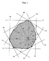
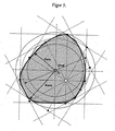
図1には、測定すべき丸線材の横断面が示されており、その外輪郭線が太実線で示されている。この丸線材には6つのレーザスキャナによって合計で12のシャドウエッジが当てられ、これらのシャドウエッジが接線T1,T2,T3,T4,T5およびT6ならびにT1’,T2’,T3’,T4’,T5’およびT6’となる。ここで、接線対T1,T1’;T2,T2’;T3,T3’;T4,T4’;T5,T5’およびT6,T6’がそれぞれ1つのレーザスキャナに属している。したがって、全体で6つのレーザスキャナが使用されている。測定すべき丸線材はそれぞれ完全にこのレーザススキャナの測定野内にある。 FIG. 1 shows a cross section of a round wire to be measured, and its outer contour line is indicated by a thick solid line. A total of 12 shadow edges are applied to this round wire by six laser scanners, and these shadow edges are tangents T 1 , T 2 , T 3 , T 4 , T 5 and T 6 and T 1 ′ , T 2. ' , T 3' , T 4 ' , T 5' and T 6 ' . Here, each of the tangent pairs T 1 , T 1 ′ ; T 2 , T 2 ′ ; T 3 , T 3 ′ ; T 4 , T 4 ′ ; T 5 , T 5 ′ and T 6 , T 6 ′ is one. Belongs to the laser scanner. Therefore, a total of six laser scanners are used. Each round wire to be measured is completely within the measurement field of the laser scanner.
測定装置の測定野の中心Z0はシャドウエッジないし接線を当接させる前により正確に求められ、校正されている。 The center Z 0 of the measuring field of the measuring device is more accurately determined and calibrated before the shadow edges or tangents are brought into contact.
この実施例において合計で12の接線を丸線材に当てる場合でも、この接線Tの個数は任意であってよい。しかし、丸線材を囲む多角形を形成するには、少なくとも3つの接線が必要である。接線は互いに対して既知の角度位置を有する。 Even when a total of 12 tangents are applied to the round wire in this embodiment, the number of tangents T may be arbitrary. However, at least three tangents are required to form a polygon surrounding the round wire. The tangents have a known angular position relative to each other.
接線が求められた後、垂線r1,r2,r3,r4,r5,r6,r1’,r2’,r3’,r4’,r5’およびr6’と、Z0から各接線までの垂直距離が求められる。 After the tangent is determined, the perpendicular lines r 1 , r 2 , r 3 , r 4 , r 5 , r 6 , r 1 ′ , r 2 ′ , r 3 ′ , r 4 ′ , r 5 ′ and r 6 ′ , The vertical distance from Z 0 to each tangent is determined.
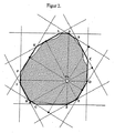
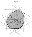
図2には、上記のようにして得られた接線が丸線材を囲む頂点A〜Lを有する多角形を形成することが示されている。図2では、この多角形は太実線で表されており、一方、丸線材は点線で表されている。 FIG. 2 shows that the tangent line obtained as described above forms a polygon having vertices A to L surrounding the round wire. In FIG. 2, this polygon is represented by a thick solid line, while the round wire is represented by a dotted line.
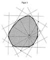
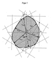
図3には、図2に示されている多角形(図3では点線で示されている)が適合させたスプライン補間による平滑後にどのような形状をとるのかが示されている。これにより、広い範囲にわたって実際の丸線材(細実線)と一致する輪郭シミュレーションが生じる。このようにして、曲線全体で使用可能なデータが得られる。言い換えれば、実際にシャドウエッジまたは接線によって求められた値の外の場所についても、データを求めることができる。 FIG. 3 shows what shape is taken after smoothing by spline interpolation to which the polygon shown in FIG. 2 (shown by a dotted line in FIG. 3) is fitted. As a result, a contour simulation that matches the actual round wire (thin solid line) over a wide range occurs. In this way, usable data is obtained for the entire curve. In other words, data can also be obtained for locations outside the values actually obtained by shadow edges or tangents.
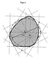
図4には、基準円(一点鎖線)に対する輪郭シミュレーションの平方形状誤差が最小値に達するように、どのようにして基準円(一点鎖線)を輪郭シミュレーション(太実線)内に置くかが図示されている。この基準円に関してその直径Drefが計算される。空間内での基準円の位置から基準中心Zpが求められる。 FIG. 4 shows how the reference circle (dashed line) is placed in the contour simulation (thick solid line) so that the square shape error of the contour simulation with respect to the reference circle (dashed line) reaches the minimum value. ing. The diameter D ref is calculated for this reference circle. A reference center Z p is obtained from the position of the reference circle in the space.
図5には、このようにして求められた中心Zpから2つのベクトルが、すなわち、基準中心Zpから輪郭シミュレーションまでの最小距離Rminと最大距離Rmaxがどのようにして求められ、これらの値から非円度が求められるかが示されている。求められた極値は輪郭シミュレーション上のどこかにありうる。それゆえ、求められた極値はまた元々の測定点の間の輪郭区間内にある角度位置にもありうる。 5 shows, such that two vectors from the center Z p obtained by, namely, the minimum distance R min and a maximum distance R max from the reference center Z p to the contour simulation how the sought, these It is shown whether the non-circularity is obtained from the value of. The obtained extreme value can be somewhere on the contour simulation. Therefore, the extrema determined can also be at an angular position that is within the contour interval between the original measurement points.
図6では、代替的な計算方法が図式的に説明されている。本発明による方法のステップf)では、基準中心Zpからローラ列の最後の2つの3ローラ台のローラディスクの方向へと延びるベクトルVGT1,VGT2およびVGT3ならびにVDT1,VDT2およびVDT3が計算される。ここで、最後より1つ前のローラ台のローラディスクの中央平面は0°、120°および240°に位置し、最後のローラ台の中央平面は60°、180°および300°に位置するものと仮定される。図6では、0°ないし180°平面は紙面に対して垂直にVGT1とVDT3を通って広がる平面内にあり、図6の垂直に走る一点鎖線の直線によって示されている。言い換えれば、ベクトルVGT1,VGT2およびVGT3は最後のローラ台のローラディスクの間の隙間の方向を指しており、一方でベクトルVDT1,VDT2およびVDT3は圧力点ないし最後のローラ台のローラの中心の方向を指している。なお、この圧力点はふつう最後より1つ前のローラ台のローラのローラ隙間がある場所にある。 In FIG. 6, an alternative calculation method is schematically illustrated. In step f) of the method according to the invention, the vectors V GT1 , V GT2 and V GT3 and V DT1 , V DT2 and V extending from the reference center Z p in the direction of the last two three-roller roller disks of the roller train. DT3 is calculated. Here, the central planes of the roller discs of the roller table immediately before the last are located at 0 °, 120 ° and 240 °, and the central planes of the last roller table are located at 60 °, 180 ° and 300 °. Is assumed. In FIG. 6, the 0 ° to 180 ° plane is in a plane extending through V GT1 and V DT3 perpendicular to the paper surface, and is indicated by the dashed-dotted straight line running vertically in FIG. In other words, the vectors V GT1 , V GT2 and V GT3 point to the direction of the gap between the roller disks of the last roller platform, while the vectors V DT1 , V DT2 and V DT3 are the pressure points or the last roller platform. The direction of the center of the roller. In addition, this pressure point is usually in a place where there is a roller gap between the rollers of the roller table one before the last.
簡単な数学的計算によって、ベクトルVGT1,VGT2およびVGT3からここで論じているローラ台の調整に関心のある値GTを計算することができる。なお、値GTは長さ寸法である。同様に、ベクトルVDT1,VDT2およびVDT3からは、同じく長さ寸法を表す値DTを計算することができる。 With simple mathematical calculations, the value GT of interest for adjusting the roller platform discussed here can be calculated from the vectors V GT1 , V GT2 and V GT3 . The value GT is a length dimension. Similarly, a value DT representing the length dimension can be calculated from the vectors V DT1 , V DT2 and V DT3 .
これは−図示の通り−個々の3ローラブロックの調整の最適化の基準となる値であり、60°の一定角度だけ互いにずれている。 This is a reference value for optimization of the adjustment of the individual three-roller blocks, as shown in the figure, and they are shifted from each other by a fixed angle of 60 °.
本発明による方法に必要な測定装置は直接最後のローラ台の後に配置されるのではなく、まずは所定の距離だけ下流に配置されることが多い。ここで、仕上げ圧延された丸線材が最後のローラ台から測定装置の測定平面までの道程において捻れてしまうという問題が存在する。この場合、この道程で丸線材が長手軸周りに捻れる角度は個々のローラ列において通常は既知である。 The measuring device required for the method according to the invention is often not arranged directly after the last roller base, but is first arranged downstream by a predetermined distance. Here, there is a problem that the round-rolled round wire rod is twisted in the path from the last roller base to the measurement plane of the measuring device. In this case, the angle at which the round wire is twisted around the longitudinal axis along this path is usually known in the individual roller rows.
図7には、丸線材の捻れにもかかわらず、所望の値GTおよびDTをいかにして計算することができるかが図示されている。図7においてaで示されている捻れ角は既知であるから、0°、120°および240°(VGT1,VGT2およびVGT3に該当)ないし60°、180°および300°(VDT1,VDT2およびVDT3に該当)の方向にない、Zpから輪郭シミュレーションまでの上記ベクトルが図6に示されているように求められる。実際、これらのベクトルも捻れ角aだけ捻れている。それゆえ、Zpを中心として角度aだけ捻れた、Zpから輪郭シミュレーション(太実線)までのベクトルVGT1,VGT2およびVGT3ならびにVDT1,VDT2およびVDT3が求められる。図7において、ベクトルVGT1,VGT2およびVGT3はそれぞれ実線の矢印で表されており、ベクトルVDT1,VDT2およびVDT3は破線の矢印で表されている。 FIG. 7 illustrates how the desired values GT and DT can be calculated despite the twist of the round wire. Since the torsion angles indicated by a in FIG. 7 are known, 0 °, 120 ° and 240 ° (corresponding to V GT1 , V GT2 and V GT3 ) to 60 °, 180 ° and 300 ° (V DT1 , The above vectors from Z p to contour simulation that are not in the direction of V DT2 and V DT3 are determined as shown in FIG. In fact, these vectors are also twisted by the twist angle a. Therefore, vectors V GT1 , V GT2 and V GT3 and V DT1 , V DT2 and V DT3 from Z p to contour simulation (thick solid line) twisted by angle a around Z p are obtained. In FIG. 7, vectors V GT1 , V GT2, and V GT3 are represented by solid arrows, and vectors V DT1 , V DT2, and V DT3 are represented by dashed arrows.
それゆえ、最後のローラ台を離れてから所定の距離でようやく測定が行われる場合であっても、3つのベクトルVGT1,VGT2およびVGT3ないしVDT1,VDT2およびVDT3のすべてを考慮して任意の角度位置aについて同じ基準中心Zpから最後のローラ台の場所でのGTおよびDTの典型値を求めることができる。 Therefore, all three vectors V GT1 , V GT2 and V GT3 to V DT1 , V DT2 and V DT3 are taken into account even if the measurement is finally performed at a predetermined distance after leaving the last roller base. Thus, it is possible to obtain typical values of GT and DT at the location of the last roller base from the same reference center Z p for an arbitrary angular position a.
ベクトルVGT1,VGT2およびVGT3ないしVDT1,VDT2およびVDT3の各ベクトルは個別に求めることができるので、本発明による方法を用いれば、各ローラ台の個々のローラの絶対送り量を求めることができる。例えば3ローラブロックのある1つのローラの圧力点が他の2つのローラの圧力点よりもさらに半径方向内側にずれているならば、これを本発明に従って求めることができる。その場合、ただ1つのローラの半径方向位置を補正するだけでよい。 Since the vectors V GT1 , V GT2 and V GT3 to V DT1 , V DT2 and V DT3 can be obtained individually, the method according to the present invention can be used to calculate the absolute feed amount of each roller on each roller base. Can be sought. For example, if the pressure point of one roller with a three-roller block is offset further radially inward than the pressure points of the other two rollers, this can be determined according to the invention. In that case, it is only necessary to correct the radial position of one roller.
Claims (10)
a)前記測定の前に、前記測定装置の測定野内の中心(Z0)がまだ定められていなければ、当該中心(Z0)を校正し定め、
b)前記中心(Z0)から前記接線(T1,T2,T3,T4,T5,T6,T1’,T2’,T3’,T4’,T5’,T6’)までの垂線(r1,r2,r3,r4,r5,r6,r1’,r2’,r3’,r4’,r5’,r6’)を求め、前記中心(Z0)から前記接線(T1−T6’)までの距離を計算し、
c)前記丸線材を囲む多角形の頂点(A−K)を計算し、輪郭を求め、
d)前記輪郭に対して基準円を次のように、すなわち、
i)前記基準円に対する前記輪郭の平方形状誤差が最小値に達する、
ii)前記基準円が前記輪郭を囲むできるだけ小さな円を描く、
iii)前記基準円が前記輪郭の中に嵌るできるだけ大きな円を描く、または
iv)前記基準円と前記基準円と同心の別の円がともに、半径の差が最小のときに、前記輪郭を包囲する
ように配置し、
e)前記基準円の直径(Dref)を計算し、空間内での位置から前記基準円の中心点を表す前記基準中心(Zp)を求め、
f)前記基準中心(Zp)から前記輪郭までの少なくとも2つのベクトルを計算し、当該データから非円度を求める、ことを特徴とする方法。 A method for measuring roundness or shape error of a round wire moving in a longitudinal direction in a roller array, as is known per se, comprising at least two laser scanners each having a photosensitive sensor and a laser. In a method of forming and measuring at least three shadow edges that form a polygon that touches and surrounds a round wire to be measured, and calculates the corresponding tangent therefrom using the measuring device provided ,
a) Before the measurement, if the center (Z 0 ) in the measurement field of the measuring device is not yet determined, the center (Z 0 ) is calibrated and determined;
b) From the center (Z 0 ) to the tangent lines (T 1 , T 2 , T 3 , T 4 , T 5 , T 6 , T 1 ′ , T 2 ′ , T 3 ′ , T 4 ′ , T 5 ′ , T 6 ') to the perpendicular line (r 1, r 2, r 3, r 4, r 5, r 6, r 1', r 2 ', r 3', r 4 ', r 5', r 6 ') And calculating the distance from the center (Z 0 ) to the tangent (T 1 -T 6 ′ ),
c) Calculate the vertices of the polygon (AK) surrounding the round wire, find the contour,
d) The reference circle for the contour is as follows:
i) the square shape error of the contour relative to the reference circle reaches a minimum value;
ii) Draw as small a circle as possible so that the reference circle surrounds the contour;
iii) Draw as large a circle as possible so that the reference circle fits within the contour, or
iv) Both the reference circle and another circle concentric with the reference circle are arranged so as to surround the contour when the difference in radius is minimum,
e) calculating the diameter (D ref ) of the reference circle, obtaining the reference center (Z p ) representing the center point of the reference circle from the position in space,
f) A method of calculating at least two vectors from the reference center (Z p ) to the contour and obtaining non-circularity from the data.
Applications Claiming Priority (3)
| Application Number | Priority Date | Filing Date | Title |
|---|---|---|---|
| EP07007089.1 | 2007-04-04 | ||
| EP07007089A EP1978329A1 (en) | 2007-04-04 | 2007-04-04 | Method for measuring the roundness of round profiles |
| PCT/EP2008/002593 WO2008122385A2 (en) | 2007-04-04 | 2008-04-01 | Method for measuring the shpericity of spherical profiles |
Publications (2)
| Publication Number | Publication Date |
|---|---|
| JP2010523948A true JP2010523948A (en) | 2010-07-15 |
| JP5145409B2 JP5145409B2 (en) | 2013-02-20 |
Family
ID=39018175
Family Applications (1)
| Application Number | Title | Priority Date | Filing Date |
|---|---|---|---|
| JP2010501423A Expired - Fee Related JP5145409B2 (en) | 2007-04-04 | 2008-04-01 | Method for measuring roundness of round wire |
Country Status (8)
| Country | Link |
|---|---|
| US (1) | US8243284B2 (en) |
| EP (2) | EP1978329A1 (en) |
| JP (1) | JP5145409B2 (en) |
| CN (1) | CN101675316B (en) |
| AT (1) | ATE547689T1 (en) |
| CA (1) | CA2682635C (en) |
| CH (1) | CH698859B1 (en) |
| WO (1) | WO2008122385A2 (en) |
Cited By (2)
| Publication number | Priority date | Publication date | Assignee | Title |
|---|---|---|---|---|
| US20200400428A1 (en) * | 2012-01-17 | 2020-12-24 | Ultrahaptics IP Two Limited | Systems and Methods of Locating a Control Object Appendage in Three Dimensional (3D) Space |
| US11720180B2 (en) | 2012-01-17 | 2023-08-08 | Ultrahaptics IP Two Limited | Systems and methods for machine control |
Families Citing this family (26)
| Publication number | Priority date | Publication date | Assignee | Title |
|---|---|---|---|---|
| WO2010037865A1 (en) * | 2008-10-02 | 2010-04-08 | Zumbach Electronic Ag | Method for determining shape parameters |
| CN102102976B (en) * | 2009-12-18 | 2013-04-24 | 西安威而信精密仪器有限公司 | Instrument capable of measuring surface profile of complicated revolving parts |
| GB2489495B (en) * | 2011-03-31 | 2013-03-06 | Rolls Royce Plc | Checking positional accuracy of features |
| EP2725320B1 (en) * | 2012-10-26 | 2016-01-20 | Zumbach Electronic Ag | Method for determining the angle of rotation of a longitudinally moving round profile in a mill train |
| CN103033144B (en) * | 2012-12-22 | 2016-05-18 | 上海市隧道工程轨道交通设计研究院 | A kind of Laser Measuring round belting and application process thereof |
| CN105188971B (en) | 2013-05-11 | 2017-10-13 | 仲巴赫电子公司 | For the method for the stamping quality for determining special-shaped bar |
| CN103383248B (en) * | 2013-07-24 | 2016-09-14 | 丽水职业技术学院 | A kind of detection method of oscillating bearing inner ring spherical outside surface sphericity |
| RU2642980C9 (en) * | 2013-09-30 | 2018-04-11 | Висока Школа Баньска - Техницка Универзита Острава | Method for contactless measurement of external sizes of metallurgical rod-like article cross sections and modular frame for its implementation |
| ES2869049T3 (en) * | 2014-04-11 | 2021-10-22 | Sms Group Gmbh | Ring rolling machine and procedure to control a ring rolling machine |
| DE112016006594A5 (en) | 2016-03-17 | 2018-12-13 | Hegenscheidt Mfd Gmbh | Method for measuring and calculating geometric parameters of the wheels of a wheelset for rail vehicles |
| CN107664483B (en) * | 2016-07-29 | 2019-06-25 | 宝山钢铁股份有限公司 | A kind of cylinder bar shape parameter measurement method |
| CN106442230A (en) * | 2016-10-11 | 2017-02-22 | 中国石油大学(华东) | Fracturing propping agent roundness and sphericity detecting method based on image processing technology |
| EP3399275A1 (en) * | 2017-05-04 | 2018-11-07 | MULTIVAC Sepp Haggenmüller SE & Co. KG | Determining the position and orientation of a conveyed promoted object |
| CN107561106B (en) * | 2017-08-31 | 2020-06-05 | 长江存储科技有限责任公司 | Method and device for measuring characterization parameters of streak-shaped morphology |
| CN107716563B (en) * | 2017-09-26 | 2019-02-26 | 西安理工大学 | Band automatic centering detection method based on infrared light |
| CN108581239B (en) * | 2018-04-10 | 2020-03-20 | 上海柏楚电子科技股份有限公司 | Method for measuring offset and compensating cutter path in real time in square tube laser cutting |
| CN108868742B (en) * | 2018-06-08 | 2022-03-29 | 中国石油天然气股份有限公司 | Method, device and storage medium for determining source of pipe type underground falling object |
| DE102018119736B4 (en) * | 2018-08-14 | 2020-10-29 | Lap Gmbh Laser Applikationen | Method for determining the position of a roll gap |
| CN109341577B (en) * | 2018-10-19 | 2020-06-12 | 北京市机械施工有限公司 | Steel pipe machining ovality detection device |
| CN111310106B (en) * | 2020-01-19 | 2024-02-06 | 浙江工业大学 | Cutting contour fitting optimization method based on successive approximation of original contour |
| CN111578866B (en) * | 2020-06-16 | 2021-04-20 | 大连理工大学 | Spatial pose calibration method for multi-line laser sensor combined measurement |
| US11933863B2 (en) | 2020-07-27 | 2024-03-19 | Changxin Memory Technologies, Inc. | Method for measuring shortest distance between capacitances and method for evaluating capacitance manufacture procedure |
| CN114001692B (en) * | 2020-07-27 | 2023-04-07 | 长鑫存储技术有限公司 | Method for measuring shortest distance between capacitors and method for evaluating capacitor manufacturing process |
| CN112025339B (en) * | 2020-08-28 | 2021-12-14 | 中钢集团西安重机有限公司 | Method for determining position of central hole of rotary tank body |
| CN114018202B (en) * | 2021-11-08 | 2024-02-02 | 绍兴职业技术学院 | Novel algorithm for rapidly evaluating roundness |
| CN113820720B (en) * | 2021-11-22 | 2022-01-25 | 成都星宇融科电力电子股份有限公司 | Three-dimensional laser center ranging method, system and terminal based on multiple reference base points |
Citations (5)
| Publication number | Priority date | Publication date | Assignee | Title |
|---|---|---|---|---|
| JPS56117107A (en) * | 1980-02-20 | 1981-09-14 | Sumitomo Metal Ind Ltd | Measuring method of profile |
| JPS63205504A (en) * | 1987-02-20 | 1988-08-25 | Sumitomo Metal Ind Ltd | Profile measuring method |
| JPH08145636A (en) * | 1994-11-22 | 1996-06-07 | Sumitomo Metal Ind Ltd | Method for measuring shape using outside diameter measuring apparatus |
| JP2001041738A (en) * | 1999-08-04 | 2001-02-16 | Tokyo Seimitsu Co Ltd | Circularity measurement method and device |
| JP2002013915A (en) * | 2000-05-11 | 2002-01-18 | Lap Gmbh Laser Applikationen | Apparatus and process for measuring thickness and out- of-roundness of long workpiece |
Family Cites Families (3)
| Publication number | Priority date | Publication date | Assignee | Title |
|---|---|---|---|---|
| DD276040A1 (en) * | 1988-10-04 | 1990-02-14 | Thaelmann Schwermaschbau Veb | METHOD FOR THE ROLLING SLIP CONTROL OF THE PRODUCT |
| DE4037383A1 (en) * | 1990-11-20 | 1992-05-21 | Mesacon Messtechnik | METHOD FOR CONTINUOUS TOUCH-FREE MEASUREMENT OF PROFILES AND DEVICE FOR CARRYING OUT THE MEASURING METHOD |
| CN1884965A (en) * | 2005-06-24 | 2006-12-27 | 鸿富锦精密工业(深圳)有限公司 | Roundness measuring system and method |
-
2007
- 2007-04-04 EP EP07007089A patent/EP1978329A1/en not_active Withdrawn
-
2008
- 2008-04-01 EP EP08748855A patent/EP2132525B1/en not_active Not-in-force
- 2008-04-01 CH CH01548/09A patent/CH698859B1/en not_active IP Right Cessation
- 2008-04-01 CA CA2682635A patent/CA2682635C/en not_active Expired - Fee Related
- 2008-04-01 US US12/594,481 patent/US8243284B2/en active Active
- 2008-04-01 JP JP2010501423A patent/JP5145409B2/en not_active Expired - Fee Related
- 2008-04-01 AT AT08748855T patent/ATE547689T1/en active
- 2008-04-01 CN CN2008800147704A patent/CN101675316B/en not_active Expired - Fee Related
- 2008-04-01 WO PCT/EP2008/002593 patent/WO2008122385A2/en active Application Filing
Patent Citations (5)
| Publication number | Priority date | Publication date | Assignee | Title |
|---|---|---|---|---|
| JPS56117107A (en) * | 1980-02-20 | 1981-09-14 | Sumitomo Metal Ind Ltd | Measuring method of profile |
| JPS63205504A (en) * | 1987-02-20 | 1988-08-25 | Sumitomo Metal Ind Ltd | Profile measuring method |
| JPH08145636A (en) * | 1994-11-22 | 1996-06-07 | Sumitomo Metal Ind Ltd | Method for measuring shape using outside diameter measuring apparatus |
| JP2001041738A (en) * | 1999-08-04 | 2001-02-16 | Tokyo Seimitsu Co Ltd | Circularity measurement method and device |
| JP2002013915A (en) * | 2000-05-11 | 2002-01-18 | Lap Gmbh Laser Applikationen | Apparatus and process for measuring thickness and out- of-roundness of long workpiece |
Cited By (2)
| Publication number | Priority date | Publication date | Assignee | Title |
|---|---|---|---|---|
| US20200400428A1 (en) * | 2012-01-17 | 2020-12-24 | Ultrahaptics IP Two Limited | Systems and Methods of Locating a Control Object Appendage in Three Dimensional (3D) Space |
| US11720180B2 (en) | 2012-01-17 | 2023-08-08 | Ultrahaptics IP Two Limited | Systems and methods for machine control |
Also Published As
| Publication number | Publication date |
|---|---|
| ATE547689T1 (en) | 2012-03-15 |
| CH698859B1 (en) | 2011-04-15 |
| CA2682635C (en) | 2014-12-09 |
| US8243284B2 (en) | 2012-08-14 |
| EP2132525A2 (en) | 2009-12-16 |
| CN101675316B (en) | 2012-07-25 |
| CA2682635A1 (en) | 2008-10-16 |
| EP2132525B1 (en) | 2012-02-29 |
| WO2008122385A2 (en) | 2008-10-16 |
| JP5145409B2 (en) | 2013-02-20 |
| CN101675316A (en) | 2010-03-17 |
| EP1978329A1 (en) | 2008-10-08 |
| US20100245843A1 (en) | 2010-09-30 |
| WO2008122385A3 (en) | 2008-12-11 |
Similar Documents
| Publication | Publication Date | Title |
|---|---|---|
| JP5145409B2 (en) | Method for measuring roundness of round wire | |
| CN102171530B (en) | Method for determining shape parameters | |
| EP3093611B1 (en) | Measuring method and device to measure the straightness error of bars and pipes | |
| JP4638732B2 (en) | Scanning system calibration method | |
| JP4571646B2 (en) | Method for calibration of a coordinate position determination device | |
| US7543393B2 (en) | Method of calibrating a scanning system | |
| CA2428377C (en) | Method of and apparatus for measuring planarity of strip, especially metal strip | |
| US6549293B2 (en) | Apparatus for process for measuring the thickness and out-of-roundness of elongate workpieces | |
| US8218153B2 (en) | Apparatus and method for improving the measurement accuracy of digital 3D geometrical measurement systems | |
| JP2010260105A (en) | Device for continuously bending elongated workpiece at predetermined radius | |
| JP2021505854A (en) | Pipe dimension measurement system | |
| JPH08105702A (en) | Calibrating method of coordinate measuring device with two shaft | |
| WO2015133027A1 (en) | Tire tread radius measurement method and tread radius measurement device used in same | |
| CN116839490A (en) | Thickness gauge with roller positioning function based on double lasers and thickness measuring method thereof | |
| US7256896B2 (en) | Method for verifying scan precision of a laser measurement machine | |
| JPH0687013B2 (en) | Roll profile measurement method | |
| JP2001269705A (en) | Device and method for sizing metallic tube | |
| JP6988434B2 (en) | Tread shape measuring method and tread shape measuring device | |
| CN111633057B (en) | Left-right tilting dynamic straightening method | |
| JPH0556804B2 (en) | ||
| KR20230067320A (en) | Method for measuring diameter of round steel bar using 3d scanner | |
| JP2001280930A (en) | Method and instrument for measuring shape of linear material | |
| FOJTIK et al. | METHOD OF NON-CONTACT MEASURING OF DIAMETER AND OVALITY OF STEEL TUBES DURING THEIR PRODUCTION. | |
| Podešva et al. | Calibration of 2D scanner with nonlinearities | |
| KR20050016971A (en) | Method of calibrating a scanning system |
Legal Events
| Date | Code | Title | Description |
|---|---|---|---|
| RD04 | Notification of resignation of power of attorney |
Free format text: JAPANESE INTERMEDIATE CODE: A7424 Effective date: 20101228 |
|
| A621 | Written request for application examination |
Free format text: JAPANESE INTERMEDIATE CODE: A621 Effective date: 20110401 |
|
| A977 | Report on retrieval |
Free format text: JAPANESE INTERMEDIATE CODE: A971007 Effective date: 20121010 |
|
| TRDD | Decision of grant or rejection written | ||
| A01 | Written decision to grant a patent or to grant a registration (utility model) |
Free format text: JAPANESE INTERMEDIATE CODE: A01 Effective date: 20121026 |
|
| A01 | Written decision to grant a patent or to grant a registration (utility model) |
Free format text: JAPANESE INTERMEDIATE CODE: A01 |
|
| A61 | First payment of annual fees (during grant procedure) |
Free format text: JAPANESE INTERMEDIATE CODE: A61 Effective date: 20121126 |
|
| FPAY | Renewal fee payment (event date is renewal date of database) |
Free format text: PAYMENT UNTIL: 20151130 Year of fee payment: 3 |
|
| R150 | Certificate of patent or registration of utility model |
Free format text: JAPANESE INTERMEDIATE CODE: R150 |
|
| LAPS | Cancellation because of no payment of annual fees |