JP2010515869A - Drive assembly for regenerative drive system - Google Patents
Drive assembly for regenerative drive system Download PDFInfo
- Publication number
- JP2010515869A JP2010515869A JP2009545762A JP2009545762A JP2010515869A JP 2010515869 A JP2010515869 A JP 2010515869A JP 2009545762 A JP2009545762 A JP 2009545762A JP 2009545762 A JP2009545762 A JP 2009545762A JP 2010515869 A JP2010515869 A JP 2010515869A
- Authority
- JP
- Japan
- Prior art keywords
- gear
- drive
- shaft
- clutch
- drive assembly
- Prior art date
- Legal status (The legal status is an assumption and is not a legal conclusion. Google has not performed a legal analysis and makes no representation as to the accuracy of the status listed.)
- Pending
Links
Images
Classifications
-
- B—PERFORMING OPERATIONS; TRANSPORTING
- B60—VEHICLES IN GENERAL
- B60W—CONJOINT CONTROL OF VEHICLE SUB-UNITS OF DIFFERENT TYPE OR DIFFERENT FUNCTION; CONTROL SYSTEMS SPECIALLY ADAPTED FOR HYBRID VEHICLES; ROAD VEHICLE DRIVE CONTROL SYSTEMS FOR PURPOSES NOT RELATED TO THE CONTROL OF A PARTICULAR SUB-UNIT
- B60W20/00—Control systems specially adapted for hybrid vehicles
- B60W20/40—Controlling the engagement or disengagement of prime movers, e.g. for transition between prime movers
-
- B—PERFORMING OPERATIONS; TRANSPORTING
- B60—VEHICLES IN GENERAL
- B60K—ARRANGEMENT OR MOUNTING OF PROPULSION UNITS OR OF TRANSMISSIONS IN VEHICLES; ARRANGEMENT OR MOUNTING OF PLURAL DIVERSE PRIME-MOVERS IN VEHICLES; AUXILIARY DRIVES FOR VEHICLES; INSTRUMENTATION OR DASHBOARDS FOR VEHICLES; ARRANGEMENTS IN CONNECTION WITH COOLING, AIR INTAKE, GAS EXHAUST OR FUEL SUPPLY OF PROPULSION UNITS IN VEHICLES
- B60K6/00—Arrangement or mounting of plural diverse prime-movers for mutual or common propulsion, e.g. hybrid propulsion systems comprising electric motors and internal combustion engines ; Control systems therefor, i.e. systems controlling two or more prime movers, or controlling one of these prime movers and any of the transmission, drive or drive units Informative references: mechanical gearings with secondary electric drive F16H3/72; arrangements for handling mechanical energy structurally associated with the dynamo-electric machine H02K7/00; machines comprising structurally interrelated motor and generator parts H02K51/00; dynamo-electric machines not otherwise provided for in H02K see H02K99/00
- B60K6/08—Prime-movers comprising combustion engines and mechanical or fluid energy storing means
- B60K6/12—Prime-movers comprising combustion engines and mechanical or fluid energy storing means by means of a chargeable fluidic accumulator
-
- B—PERFORMING OPERATIONS; TRANSPORTING
- B60—VEHICLES IN GENERAL
- B60W—CONJOINT CONTROL OF VEHICLE SUB-UNITS OF DIFFERENT TYPE OR DIFFERENT FUNCTION; CONTROL SYSTEMS SPECIALLY ADAPTED FOR HYBRID VEHICLES; ROAD VEHICLE DRIVE CONTROL SYSTEMS FOR PURPOSES NOT RELATED TO THE CONTROL OF A PARTICULAR SUB-UNIT
- B60W10/00—Conjoint control of vehicle sub-units of different type or different function
- B60W10/02—Conjoint control of vehicle sub-units of different type or different function including control of driveline clutches
-
- F—MECHANICAL ENGINEERING; LIGHTING; HEATING; WEAPONS; BLASTING
- F16—ENGINEERING ELEMENTS AND UNITS; GENERAL MEASURES FOR PRODUCING AND MAINTAINING EFFECTIVE FUNCTIONING OF MACHINES OR INSTALLATIONS; THERMAL INSULATION IN GENERAL
- F16D—COUPLINGS FOR TRANSMITTING ROTATION; CLUTCHES; BRAKES
- F16D48/00—External control of clutches
- F16D48/06—Control by electric or electronic means, e.g. of fluid pressure
-
- B—PERFORMING OPERATIONS; TRANSPORTING
- B60—VEHICLES IN GENERAL
- B60W—CONJOINT CONTROL OF VEHICLE SUB-UNITS OF DIFFERENT TYPE OR DIFFERENT FUNCTION; CONTROL SYSTEMS SPECIALLY ADAPTED FOR HYBRID VEHICLES; ROAD VEHICLE DRIVE CONTROL SYSTEMS FOR PURPOSES NOT RELATED TO THE CONTROL OF A PARTICULAR SUB-UNIT
- B60W10/00—Conjoint control of vehicle sub-units of different type or different function
- B60W10/04—Conjoint control of vehicle sub-units of different type or different function including control of propulsion units
-
- B—PERFORMING OPERATIONS; TRANSPORTING
- B60—VEHICLES IN GENERAL
- B60W—CONJOINT CONTROL OF VEHICLE SUB-UNITS OF DIFFERENT TYPE OR DIFFERENT FUNCTION; CONTROL SYSTEMS SPECIALLY ADAPTED FOR HYBRID VEHICLES; ROAD VEHICLE DRIVE CONTROL SYSTEMS FOR PURPOSES NOT RELATED TO THE CONTROL OF A PARTICULAR SUB-UNIT
- B60W20/00—Control systems specially adapted for hybrid vehicles
-
- F—MECHANICAL ENGINEERING; LIGHTING; HEATING; WEAPONS; BLASTING
- F16—ENGINEERING ELEMENTS AND UNITS; GENERAL MEASURES FOR PRODUCING AND MAINTAINING EFFECTIVE FUNCTIONING OF MACHINES OR INSTALLATIONS; THERMAL INSULATION IN GENERAL
- F16D—COUPLINGS FOR TRANSMITTING ROTATION; CLUTCHES; BRAKES
- F16D2500/00—External control of clutches by electric or electronic means
- F16D2500/10—System to be controlled
- F16D2500/104—Clutch
- F16D2500/10406—Clutch position
- F16D2500/10418—Accessory clutch, e.g. cooling fan, air conditioning
-
- F—MECHANICAL ENGINEERING; LIGHTING; HEATING; WEAPONS; BLASTING
- F16—ENGINEERING ELEMENTS AND UNITS; GENERAL MEASURES FOR PRODUCING AND MAINTAINING EFFECTIVE FUNCTIONING OF MACHINES OR INSTALLATIONS; THERMAL INSULATION IN GENERAL
- F16D—COUPLINGS FOR TRANSMITTING ROTATION; CLUTCHES; BRAKES
- F16D2500/00—External control of clutches by electric or electronic means
- F16D2500/30—Signal inputs
- F16D2500/31—Signal inputs from the vehicle
- F16D2500/3108—Vehicle speed
- F16D2500/3109—Vehicle acceleration
-
- F—MECHANICAL ENGINEERING; LIGHTING; HEATING; WEAPONS; BLASTING
- F16—ENGINEERING ELEMENTS AND UNITS; GENERAL MEASURES FOR PRODUCING AND MAINTAINING EFFECTIVE FUNCTIONING OF MACHINES OR INSTALLATIONS; THERMAL INSULATION IN GENERAL
- F16D—COUPLINGS FOR TRANSMITTING ROTATION; CLUTCHES; BRAKES
- F16D2500/00—External control of clutches by electric or electronic means
- F16D2500/70—Details about the implementation of the control system
- F16D2500/704—Output parameters from the control unit; Target parameters to be controlled
- F16D2500/70422—Clutch parameters
- F16D2500/70424—Outputting a clutch engaged-disengaged signal
-
- Y—GENERAL TAGGING OF NEW TECHNOLOGICAL DEVELOPMENTS; GENERAL TAGGING OF CROSS-SECTIONAL TECHNOLOGIES SPANNING OVER SEVERAL SECTIONS OF THE IPC; TECHNICAL SUBJECTS COVERED BY FORMER USPC CROSS-REFERENCE ART COLLECTIONS [XRACs] AND DIGESTS
- Y02—TECHNOLOGIES OR APPLICATIONS FOR MITIGATION OR ADAPTATION AGAINST CLIMATE CHANGE
- Y02T—CLIMATE CHANGE MITIGATION TECHNOLOGIES RELATED TO TRANSPORTATION
- Y02T10/00—Road transport of goods or passengers
- Y02T10/60—Other road transportation technologies with climate change mitigation effect
- Y02T10/62—Hybrid vehicles
Landscapes
- Engineering & Computer Science (AREA)
- Mechanical Engineering (AREA)
- Transportation (AREA)
- Chemical & Material Sciences (AREA)
- Combustion & Propulsion (AREA)
- General Engineering & Computer Science (AREA)
- Physics & Mathematics (AREA)
- Fluid Mechanics (AREA)
- Automation & Control Theory (AREA)
- Reciprocating Pumps (AREA)
- Arrangement Or Mounting Of Propulsion Units For Vehicles (AREA)
- Gear Transmission (AREA)
- Details And Applications Of Rotary Liquid Pumps (AREA)
Abstract
ポンプ/モーター(12)及び電子油圧制御システム(13)を組み込む再生駆動システム(11)のための駆動アセンブリ(10)。貨物自動車に組み込まれ、貨物自動車が減速しているとき、組立体(10)の第2のクラッチ部分(20)が、第1のクラッチ部分(19)に係合され、それによってポンプ/モーター(12)を駆動する。ポンプ/モーター(12)は、クラッチ(18)の動作によって動作不能になる。 A drive assembly (10) for a regenerative drive system (11) incorporating a pump / motor (12) and an electrohydraulic control system (13). When incorporated in a lorry and when the lorry is decelerating, the second clutch portion (20) of the assembly (10) is engaged with the first clutch portion (19), thereby pump / motor ( 12) is driven. The pump / motor (12) becomes inoperable due to the operation of the clutch (18).
Description
本発明は、クラッチを使用する駆動アセンブリに、より詳細には、限定するものではないが、貨物自動車等の自動車のための再生駆動システム用の駆動アセンブリに関する。 The present invention relates to a drive assembly using a clutch, and more particularly, but not exclusively, to a drive assembly for a regenerative drive system for a vehicle such as a truck.
(発明の背景)
ポンプ/モーター、電気制御システム、及び油圧制御システムを含み、貨物自動車が減速しているときに通常消散されるエネルギーを回収する目的で、特に貨物自動車に適合された再生駆動システムが、国際特許出願PCT/AU2005/001241、PCT/AU2006/001426、PCT/AU2003/001235、PCT/AU2003/001238、PCT/AU2003/001236、PCT/AU2003/001237、PCT/AU2003/000757、PCT/AU2003/001237、PCT/AU2003/00040、PCT/AU2003/00042、及びPCT/AU2003/00041に記載されている。
(Background of the Invention)
An international patent application has been filed for a regenerative drive system that includes a pump / motor, electrical control system, and hydraulic control system, and is specifically adapted to a lorry for the purpose of recovering energy normally dissipated when the lorry is decelerating PCT / AU2005 / 001241, PCT / AU2006 / 001426, PCT / AU2003 / 001235, PCT / AU2003 / 001238, PCT / AU2003 / 001236, PCT / AU2003 / 001237, PCT / AU2003 / 000757, PCT / AU2003 / 001237, PCT / AU2003 / 00040, PCT / AU2003 / 00042, and PCT / AU2003 / 00041.
再生駆動システムは、一般的に、貨物自動車の主駆動軸(例えばテール軸)により駆動されている。これは、駆動軸に対して横方向に位置がずれ、且つ貯蔵部(リザーバ)に充電するために作動されるポンプに駆動軸を連結するギアボックスの提供を含む。これらの再生駆動システムの目的がエネルギーを取り込むことであるにもかかわらず、それらはまた、使用される様々なギア機構のためにエネルギーを喪失する。 The regeneration drive system is generally driven by a main drive shaft (for example, a tail shaft) of a truck. This includes the provision of a gearbox that is laterally offset with respect to the drive shaft and that couples the drive shaft to a pump that is actuated to charge a reservoir. Despite the purpose of these regenerative drive systems to capture energy, they also lose energy due to the various gear mechanisms used.
(本発明の目的)
本発明の目的は、上記の不都合を解決するか又は実質的に改善することである。
(Object of the present invention)
The object of the present invention is to solve or substantially improve the above disadvantages.
(発明の開示)
長手方向軸を有し、前記軸のまわりを回転可能に駆動されるシャフトと、
シャフトを取り囲むクラッチであって、シャフトと共に回転するようにシャフトと関連づけられた第1のクラッチ部分、第1のクラッチ部分と駆動するように関連づけられるように、第1のクラッチ部分との係合のために選択的に移動可能な第2のクラッチ部分、及び、第2のクラッチ部分と駆動するように関連づけられるように、第2のクラッチ部分と係合される駆動部材を有するクラッチと、
を含む駆動アセンブリが、本願明細書に開示される。
(Disclosure of the Invention)
A shaft having a longitudinal axis and driven to rotate about said axis;
A clutch surrounding the shaft, the first clutch portion being associated with the shaft for rotation with the shaft, the engagement with the first clutch portion being associated for driving with the first clutch portion. A second clutch portion that is selectively movable for and a clutch having a drive member engaged with the second clutch portion to be associated with driving the second clutch portion;
A drive assembly is disclosed herein.
好ましくは、前記駆動部材は、前記長手方向軸のまわりを回転可能な第1ギアであり、前記組立体は、第1ギアにかみ合うように係合され且つギア軸のまわりを回転可能な第2ギアを含み、ギア軸は、前記長手方向軸から横方向に位置がずれている。 Preferably, the drive member is a first gear rotatable about the longitudinal axis, and the assembly is engaged with the first gear and is second rotatable about the gear axis. Including a gear, the gear shaft is laterally offset from the longitudinal axis.
上記駆動アセンブリと、上記駆動アセンブリによって駆動され且つ前記第2ギアを駆動するように前記第2ギアに接続されたポンプとを含む再生駆動システムが、更に本願明細書に開示される。 Further disclosed herein is a regenerative drive system that includes the drive assembly and a pump driven by the drive assembly and connected to the second gear to drive the second gear.
好ましくは、前記ギア軸は、概ね平行であるが、前記長手方向軸から横方向に間隔を置いて配置される。 Preferably, the gear shafts are generally parallel but spaced laterally from the longitudinal axis.
(好ましい実施例の詳細な説明)
以下、再生駆動システム用の駆動アセンブリを概略的に示す添付図面を参照して、本発明の好ましい形態を一例として説明する。
Detailed Description of the Preferred Embodiment
Preferred embodiments of the present invention will now be described by way of example with reference to the accompanying drawings which schematically show a drive assembly for a regenerative drive system.
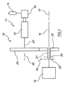
添付図面には、ポンプ/モーター12と、貯蔵部(リザーバ)14に加圧作動液を送る電子油圧制御システム13とを組み込む、再生駆動システム11用の駆動アセンブリ10が概略的に示される。ポンプ/モーター12が駆動されているとき、貯蔵部14には加圧作動液が満たされる。しかしながら、ポンプ/モーター12はまた、加圧作動液を貯蔵部14からポンプ/モーター12へ送ることによって駆動されることができ、それによりポンプ/モーター12が駆動アセンブリ10を駆動することができる。
The accompanying drawings schematically illustrate a
駆動アセンブリ10は、貨物自動車のエンジン、ギアボックス、及びクラッチアセンブリ15に連結される。組立体15から後方に延伸するのは、リアアクセルまで延伸するドライブシャフト(駆動軸)16であり、貨物自動車は一般的にドライブシャフト16により駆動される。シャフト16は、長手方向軸17を有する。
シャフト16を取り囲むのは、シャフト16がその長手方向軸17のまわりに駆動されるときにシャフト16と共に回転するように、シャフト16に固定されるか又は少なくともシャフト16と動作可能なように関連づけられた第1のクラッチ部分19を有するクラッチ18である。クラッチ18は第2のクラッチ部分20を含み、第2のクラッチ部分20は、第1のクラッチ部分19に対して駆動するように接続されるように、第1のクラッチ部分19との係合のために選択的に移動可能である。第1のクラッチ部分19から間隔を置いて配置されているとき、クラッチ部分20は相対的に静止している。
Surrounding the
第2のクラッチ部分20に固定されるか又は取り付けられるのはスリーブ21であり、スリーブ21には第1ギア22が取り付けられる。第1ギア22は、その長手方向の回転軸として軸17を有し、軸17のまわりを第1のクラッチ部分20と一致(調和)して回転する。
Fixed or attached to the
ギア22にかみ合い係合されるのは、回転ギア軸26を有する第2ギア25であり、回転ギア軸26は、軸17に概ね平行であるが軸17から横方向に間隔を置いて配置される。
Engageably engaged with the
ギア25は、再生駆動システム11のポンプ/モーター12に、シャフト27を介して接続される。
The
上記した駆動アセンブリ10の動作において、貨物自動車が減速しているとき、ギア22がギア25及びポンプ/モーター12と共に駆動されるように、第2のクラッチ部分20は第1のクラッチ部分19に係合される。ポンプ/モーター12は、そのとき貯蔵部14を充填(チャージ)する。貯蔵部14からのエネルギーが使用されるとき、クラッチ部分19及び20は再び係合され、加圧作動液が貯蔵部14からポンプ/モーター12に送られ、それによりシステム11がシャフト16を駆動する。
In the operation of the
ポンプ/モーター12が動作中でないとき、クラッチ18は係合を外され、つまり、クラッチ部分19及び20は間隔を置いて配置されるので、クラッチ部分20は概ね静止している。したがって、ポンプ/モーター12と同様にギア22及び25は、基本的に動作不能であり、それによってエネルギーの損失を抑える。
When the pump /
好ましくは、組立体15は、クラッチ18がポンプ/モーター12を駆動するために係合されるときに、係合を外されるクラッチ28を含む。
Preferably, the
Claims (5)
前記シャフトを取り囲むクラッチであって、前記シャフトと共に回転させられるように前記シャフトと関連づけられた第1のクラッチ部分、前記第1のクラッチ部分と駆動するように関連づけられるように、前記第1のクラッチ部分との係合のために選択的に移動可能な第2のクラッチ部分、及び、前記第2のクラッチ部分と駆動するように関連づけられるように、第2のクラッチ部分に係合される駆動部材を有するクラッチと、
を含む駆動アセンブリ。 A shaft having a longitudinal axis and driven rotatably about said axis;
A clutch surrounding the shaft, the first clutch portion being associated with the shaft to be rotated with the shaft, the first clutch being associated with driving the first clutch portion; A second clutch portion selectively movable for engagement with the portion, and a drive member engaged with the second clutch portion to be associated with driving the second clutch portion A clutch having
Including drive assembly.
前記駆動アセンブリによって駆動され、前記第2ギアを駆動するように前記第2ギアに接続しているポンプと、
を含む再生駆動システムの組合せ。 The drive assembly of claim 1, 2, or 3;
A pump driven by the drive assembly and connected to the second gear to drive the second gear;
Combination of playback drive system including
Applications Claiming Priority (2)
| Application Number | Priority Date | Filing Date | Title |
|---|---|---|---|
| AU2007900200A AU2007900200A0 (en) | 2007-01-16 | Drive assembly for a regenerative drive system | |
| PCT/AU2008/000021 WO2008086562A1 (en) | 2007-01-16 | 2008-01-10 | Drive assembly for a regenerative drive system |
Publications (2)
| Publication Number | Publication Date |
|---|---|
| JP2010515869A true JP2010515869A (en) | 2010-05-13 |
| JP2010515869A5 JP2010515869A5 (en) | 2011-02-17 |
Family
ID=39635569
Family Applications (1)
| Application Number | Title | Priority Date | Filing Date |
|---|---|---|---|
| JP2009545762A Pending JP2010515869A (en) | 2007-01-16 | 2008-01-10 | Drive assembly for regenerative drive system |
Country Status (6)
| Country | Link |
|---|---|
| US (1) | US20100140043A1 (en) |
| EP (1) | EP2117900A1 (en) |
| JP (1) | JP2010515869A (en) |
| CN (1) | CN101636302B (en) |
| AU (1) | AU2008207329A1 (en) |
| WO (1) | WO2008086562A1 (en) |
Families Citing this family (7)
| Publication number | Priority date | Publication date | Assignee | Title |
|---|---|---|---|---|
| BE1021140B1 (en) | 2013-04-09 | 2016-01-08 | Cnh Industrial Belgium Nv | A HYBRID DRIVE SYSTEM FOR A HARVESTER |
| CN104627149A (en) * | 2014-12-16 | 2015-05-20 | 广西大学 | Automobile brake energy recycling device |
| CN106369130A (en) * | 2015-07-21 | 2017-02-01 | 熵零股份有限公司 | Centrifugal energy adjustment system |
| CN106369127A (en) * | 2015-07-21 | 2017-02-01 | 熵零股份有限公司 | Gear pump energy adjustment system |
| CN104972899A (en) * | 2015-08-02 | 2015-10-14 | 青岛大学 | Electro-hydraulic hybrid drive main reducer active bevel gear system |
| DE102015224664A1 (en) * | 2015-12-09 | 2017-06-14 | Zf Friedrichshafen Ag | Positive coupling with a return element |
| CN109538723B (en) * | 2018-12-29 | 2024-03-26 | 京信通信技术(广州)有限公司 | Antenna, transmission device for electric downward inclination adjustment and transmission assembly |
Citations (4)
| Publication number | Priority date | Publication date | Assignee | Title |
|---|---|---|---|---|
| JPH01168521A (en) * | 1987-12-24 | 1989-07-04 | Sanwa Seiki Co Ltd | Brake energy reutilizing method for vehicle |
| JPH0455129A (en) * | 1990-06-20 | 1992-02-21 | Nissan Motor Co Ltd | Braking energy regeneration device |
| JPH07156765A (en) * | 1993-12-03 | 1995-06-20 | Mitsubishi Motors Corp | Braking energy regenerator device |
| JP2000016114A (en) * | 1998-07-03 | 2000-01-18 | Mitsubishi Motors Corp | Brake energy regenerating device |
Family Cites Families (32)
| Publication number | Priority date | Publication date | Assignee | Title |
|---|---|---|---|---|
| US3772933A (en) * | 1970-10-12 | 1973-11-20 | Ardie Werk Gmbh | Means for performing gear changes in multi-ratio gear-boxes |
| US3892283A (en) * | 1974-02-19 | 1975-07-01 | Advanced Power Systems | Hydraulic drive |
| DE2515048C3 (en) * | 1975-04-07 | 1982-02-18 | M.A.N. Maschinenfabrik Augsburg-Nuernberg Ag, 8000 Muenchen | Drive arrangement with energy storage, in particular for road vehicles |
| FR2360439A1 (en) * | 1976-08-06 | 1978-03-03 | Renault | HYBRID TRANSMISSION DEVICE FOR MOTOR VEHICLES WITH THERMAL ENGINE |
| US4132283A (en) * | 1976-08-08 | 1979-01-02 | Mccurry Jere L | System to supplement engine power |
| US4351409A (en) * | 1980-11-14 | 1982-09-28 | General Motors Corporation | Vehicle drive system with energy storage and retrieval |
| FR2527288B1 (en) * | 1982-05-19 | 1987-10-09 | Renault Vehicules Ind | OLEOPNEUMATIC BRAKE ENERGY RECOVERY DEVICE FOR URBAN VEHICLE |
| US4741410A (en) * | 1985-07-05 | 1988-05-03 | Advanced Energy Systems Inc. | Energy storage automotive drive system particularly adaptable for retrofitting |
| US5085101A (en) * | 1989-02-13 | 1992-02-04 | Anchor Tech, Inc. | Apparatus for exerting a braking torque upon a rotating shaft |
| US5224563A (en) * | 1990-05-23 | 1993-07-06 | Souichi Iizuka | Energy regenerating mechanism of an automobile |
| US5279527A (en) * | 1992-04-17 | 1994-01-18 | Crockett Samuel J | Shiftless, continuously-aligning transmission |
| US5495912A (en) * | 1994-06-03 | 1996-03-05 | The United States Of America As Represented By The Administrator Of The U.S. Environmental Protection Agency | Hybrid powertrain vehicle |
| WO1998025093A1 (en) * | 1996-12-05 | 1998-06-11 | Showa Aluminum Corporation | Heat exchanger |
| NZ500627A (en) * | 1997-04-18 | 2001-01-26 | Transp Energy Systems Pty Ltd | Hybrid propulsion system for road vehicles with three drive units coupled to power-splitting transmission |
| BR9914241A (en) * | 1998-10-02 | 2001-06-19 | Luk Lamellen Und Kupplungtsbau | Transmission with at least two axles and an electric machine or an automatic disc clutch |
| DE10036504B4 (en) * | 1999-08-02 | 2011-05-19 | Schaeffler Technologies Gmbh & Co. Kg | powertrain |
| DE19955312B4 (en) * | 1999-11-17 | 2005-10-27 | Jungheinrich Ag | Drive system for industrial trucks |
| US20020088970A1 (en) * | 2001-01-05 | 2002-07-11 | Motorola, Inc. | Self-assembled quantum structures and method for fabricating same |
| JP4179465B2 (en) * | 2002-07-31 | 2008-11-12 | 株式会社小松製作所 | Construction machinery |
| US6986725B2 (en) * | 2002-11-01 | 2006-01-17 | Eaton Corporation | Continuously variable stepped transmission |
| US6808953B2 (en) * | 2002-12-31 | 2004-10-26 | Robert Bosch Gmbh | Gap tuning for surface micromachined structures in an epitaxial reactor |
| US7214156B2 (en) * | 2004-06-18 | 2007-05-08 | Eaton Corporation | Start and operation sequences for hybrid motor vehicles |
| US7273122B2 (en) * | 2004-09-30 | 2007-09-25 | Bosch Rexroth Corporation | Hybrid hydraulic drive system with engine integrated hydraulic machine |
| US7597172B1 (en) * | 2005-04-22 | 2009-10-06 | Parker-Hannifin Corporation | Gear box for hydraulic energy recovery |
| DE102005054767A1 (en) * | 2005-11-17 | 2007-05-24 | Daimlerchrysler Ag | Method for controlling and control device of an automated, unsynchronized gear change transmission of a motor vehicle |
| DE102006006583A1 (en) * | 2005-12-20 | 2007-06-21 | Robert Bosch Gmbh | Drive with energy recovery |
| DE102005060990A1 (en) * | 2005-12-20 | 2007-06-28 | Bosch Rexroth Aktiengesellschaft | Drive and hydrostatic piston engine with recovery of braking energy |
| US20070284170A1 (en) * | 2006-06-13 | 2007-12-13 | Kuras Brian D | Retarding control for hydromechanical drive machine |
| US20080242498A1 (en) * | 2007-03-29 | 2008-10-02 | Ford Global Technologies, Llc | Hybrid vehicle integrated transmission system |
| US9352734B2 (en) * | 2008-05-19 | 2016-05-31 | Parker-Hannifin Corporation | Brake interface circuit for hybrid drive system |
| US8302720B2 (en) * | 2009-01-28 | 2012-11-06 | Robert Bosch Gmbh | Energy storage system for a hybrid vehicle |
| US7913791B2 (en) * | 2009-05-04 | 2011-03-29 | Robert Bosch Gmbh | Energy storage system for a hybrid vehicle |
-
2008
- 2008-01-10 CN CN200880002254XA patent/CN101636302B/en not_active Expired - Fee Related
- 2008-01-10 EP EP08700319A patent/EP2117900A1/en not_active Withdrawn
- 2008-01-10 WO PCT/AU2008/000021 patent/WO2008086562A1/en active Application Filing
- 2008-01-10 US US12/523,315 patent/US20100140043A1/en not_active Abandoned
- 2008-01-10 AU AU2008207329A patent/AU2008207329A1/en not_active Abandoned
- 2008-01-10 JP JP2009545762A patent/JP2010515869A/en active Pending
Patent Citations (4)
| Publication number | Priority date | Publication date | Assignee | Title |
|---|---|---|---|---|
| JPH01168521A (en) * | 1987-12-24 | 1989-07-04 | Sanwa Seiki Co Ltd | Brake energy reutilizing method for vehicle |
| JPH0455129A (en) * | 1990-06-20 | 1992-02-21 | Nissan Motor Co Ltd | Braking energy regeneration device |
| JPH07156765A (en) * | 1993-12-03 | 1995-06-20 | Mitsubishi Motors Corp | Braking energy regenerator device |
| JP2000016114A (en) * | 1998-07-03 | 2000-01-18 | Mitsubishi Motors Corp | Brake energy regenerating device |
Also Published As
| Publication number | Publication date |
|---|---|
| CN101636302A (en) | 2010-01-27 |
| US20100140043A1 (en) | 2010-06-10 |
| EP2117900A1 (en) | 2009-11-18 |
| AU2008207329A1 (en) | 2008-07-24 |
| CN101636302B (en) | 2013-08-28 |
| WO2008086562A1 (en) | 2008-07-24 |
Similar Documents
| Publication | Publication Date | Title |
|---|---|---|
| JP6209297B1 (en) | 2-speed transaxle for electric vehicles | |
| JP2010515869A (en) | Drive assembly for regenerative drive system | |
| US9234565B2 (en) | Two-speed transmission and electric vehicle | |
| JP5883225B2 (en) | Speed change transmission device for powertrain of vehicle with motor and hybrid vehicle with motor using the same | |
| US10137767B2 (en) | Power transmission unit for vehicle | |
| US20110212803A1 (en) | Drive for a vehicle, and method for propelling a vehicle | |
| JP6135418B2 (en) | Power transmission device for hybrid vehicle | |
| JP2013510027A (en) | Hybrid vehicle transmission | |
| JP2010241424A (en) | Method and device for operating hybrid vehicle | |
| JP2008037421A (en) | Axle drive unit for drive train | |
| JP2007534553A (en) | Hybrid power unit and operation method thereof | |
| MY147070A (en) | Transmission, straddle type vehicle provided with the same, and control method for transmission | |
| US20170190246A1 (en) | Speed transmission device for moving a motor vehicle, notably a two-wheeled motor vehicle | |
| CN104024013A (en) | Flywheel module for a vehicle, as well as methods of operating the flywheel module | |
| JP5086667B2 (en) | Hybrid vehicle | |
| CN202301900U (en) | Automotive automatic speed changer and electric vehicle | |
| JP2017534033A (en) | Transmission for operating an automobile vehicle, in particular, at least two-wheeled power vehicle, and a power train using the same | |
| WO2013008855A1 (en) | Manual transmission | |
| JP5985260B2 (en) | Electric power steering and compressor integrated device and operation control method thereof | |
| JP6794313B2 (en) | Power transmission device with parking brake | |
| JP2017538900A (en) | Transmission for operating an automobile vehicle, in particular at least two-wheeled power vehicle, and a power train using the same, particularly for a hybrid vehicle | |
| CN1978937A (en) | Transmission damping apparatus and method | |
| KR20130013282A (en) | Device combined motor driven power steering with compressor | |
| EP2240340B1 (en) | Hydraulic power output unit and hydraulic hybrid drive system including same | |
| KR100473288B1 (en) | Apparatus for transmitting auxiliary power of automobile |
Legal Events
| Date | Code | Title | Description |
|---|---|---|---|
| A521 | Request for written amendment filed |
Free format text: JAPANESE INTERMEDIATE CODE: A523 Effective date: 20101227 |
|
| A621 | Written request for application examination |
Free format text: JAPANESE INTERMEDIATE CODE: A621 Effective date: 20101227 |
|
| A977 | Report on retrieval |
Free format text: JAPANESE INTERMEDIATE CODE: A971007 Effective date: 20121212 |
|
| A131 | Notification of reasons for refusal |
Free format text: JAPANESE INTERMEDIATE CODE: A131 Effective date: 20130108 |
|
| A601 | Written request for extension of time |
Free format text: JAPANESE INTERMEDIATE CODE: A601 Effective date: 20130405 |
|
| A602 | Written permission of extension of time |
Free format text: JAPANESE INTERMEDIATE CODE: A602 Effective date: 20130412 |
|
| A521 | Request for written amendment filed |
Free format text: JAPANESE INTERMEDIATE CODE: A523 Effective date: 20130705 |
|
| A131 | Notification of reasons for refusal |
Free format text: JAPANESE INTERMEDIATE CODE: A131 Effective date: 20130917 |
|
| A02 | Decision of refusal |
Free format text: JAPANESE INTERMEDIATE CODE: A02 Effective date: 20140304 |