JP2010514501A - Vented phlebotomy needle with flashback chamber - Google Patents
Vented phlebotomy needle with flashback chamber Download PDFInfo
- Publication number
- JP2010514501A JP2010514501A JP2009544044A JP2009544044A JP2010514501A JP 2010514501 A JP2010514501 A JP 2010514501A JP 2009544044 A JP2009544044 A JP 2009544044A JP 2009544044 A JP2009544044 A JP 2009544044A JP 2010514501 A JP2010514501 A JP 2010514501A
- Authority
- JP
- Japan
- Prior art keywords
- needle
- opening
- blood
- phlebotomy
- proximal
- Prior art date
- Legal status (The legal status is an assumption and is not a legal conclusion. Google has not performed a legal analysis and makes no representation as to the accuracy of the status listed.)
- Withdrawn
Links
Images


Classifications
-
- A—HUMAN NECESSITIES
- A61—MEDICAL OR VETERINARY SCIENCE; HYGIENE
- A61B—DIAGNOSIS; SURGERY; IDENTIFICATION
- A61B5/00—Measuring for diagnostic purposes; Identification of persons
- A61B5/15—Devices for taking samples of blood
- A61B5/153—Devices specially adapted for taking samples of venous or arterial blood, e.g. with syringes
- A61B5/154—Devices using pre-evacuated means
- A61B5/1545—Devices using pre-evacuated means comprising means for indicating vein or arterial entry
-
- A—HUMAN NECESSITIES
- A61—MEDICAL OR VETERINARY SCIENCE; HYGIENE
- A61B—DIAGNOSIS; SURGERY; IDENTIFICATION
- A61B5/00—Measuring for diagnostic purposes; Identification of persons
- A61B5/15—Devices for taking samples of blood
- A61B5/150007—Details
- A61B5/150015—Source of blood
- A61B5/15003—Source of blood for venous or arterial blood
-
- A—HUMAN NECESSITIES
- A61—MEDICAL OR VETERINARY SCIENCE; HYGIENE
- A61B—DIAGNOSIS; SURGERY; IDENTIFICATION
- A61B5/00—Measuring for diagnostic purposes; Identification of persons
- A61B5/15—Devices for taking samples of blood
- A61B5/150007—Details
- A61B5/150206—Construction or design features not otherwise provided for; manufacturing or production; packages; sterilisation of piercing element, piercing device or sampling device
- A61B5/150213—Venting means
-
- A—HUMAN NECESSITIES
- A61—MEDICAL OR VETERINARY SCIENCE; HYGIENE
- A61B—DIAGNOSIS; SURGERY; IDENTIFICATION
- A61B5/00—Measuring for diagnostic purposes; Identification of persons
- A61B5/15—Devices for taking samples of blood
- A61B5/150007—Details
- A61B5/150374—Details of piercing elements or protective means for preventing accidental injuries by such piercing elements
- A61B5/150381—Design of piercing elements
- A61B5/150389—Hollow piercing elements, e.g. canulas, needles, for piercing the skin
-
- A—HUMAN NECESSITIES
- A61—MEDICAL OR VETERINARY SCIENCE; HYGIENE
- A61B—DIAGNOSIS; SURGERY; IDENTIFICATION
- A61B5/00—Measuring for diagnostic purposes; Identification of persons
- A61B5/15—Devices for taking samples of blood
- A61B5/150007—Details
- A61B5/150374—Details of piercing elements or protective means for preventing accidental injuries by such piercing elements
- A61B5/150381—Design of piercing elements
- A61B5/150473—Double-ended needles, e.g. used with pre-evacuated sampling tubes
-
- A—HUMAN NECESSITIES
- A61—MEDICAL OR VETERINARY SCIENCE; HYGIENE
- A61B—DIAGNOSIS; SURGERY; IDENTIFICATION
- A61B5/00—Measuring for diagnostic purposes; Identification of persons
- A61B5/15—Devices for taking samples of blood
- A61B5/150007—Details
- A61B5/150374—Details of piercing elements or protective means for preventing accidental injuries by such piercing elements
- A61B5/150534—Design of protective means for piercing elements for preventing accidental needle sticks, e.g. shields, caps, protectors, axially extensible sleeves, pivotable protective sleeves
- A61B5/150572—Pierceable protectors, e.g. shields, caps, sleeves or films, e.g. for hygienic purposes
-
- A—HUMAN NECESSITIES
- A61—MEDICAL OR VETERINARY SCIENCE; HYGIENE
- A61B—DIAGNOSIS; SURGERY; IDENTIFICATION
- A61B5/00—Measuring for diagnostic purposes; Identification of persons
- A61B5/15—Devices for taking samples of blood
- A61B5/150007—Details
- A61B5/150732—Needle holders, for instance for holding the needle by the hub, used for example with double-ended needle and pre-evacuated tube
Abstract
フラッシュバックの可視化を容易にする構造を含む瀉血針が開示される。一実施形態において、針の中央部分は穴または開口部を含み、該穴または開口部は、針によって画定された流路と連通し、透明の筐体が、開口部の周りに位置決めされ、針を通る血流の可視化を容易にする。空気の通過を可能にし、針を通る血流の表示を提供する材料が、開口部を覆い位置決めされる。一実施形態において、材料は、プラグの形であるか、または代替として、パッチまたはカラーの形である。材料は、透明の筐体の中に入れられ得るか、または透明の筐体に窓を提供し得る。別の実施形態において、瀉血針は、針と、受動通気孔を有する筐体と、筐体の血流を可視化するための観察領域とを含む。A hemostasis needle is disclosed that includes a structure that facilitates flashback visualization. In one embodiment, the central portion of the needle includes a hole or opening, which communicates with the flow path defined by the needle, and a transparent housing is positioned around the opening, the needle Facilitates visualization of blood flow through A material that allows the passage of air and provides an indication of blood flow through the needle is positioned over the opening. In one embodiment, the material is in the form of a plug or, alternatively, in the form of a patch or a collar. The material can be encased in a transparent housing or can provide a window in the transparent housing. In another embodiment, a phlebotomy needle includes a needle, a housing having passive vents, and an observation area for visualizing blood flow in the housing.
Description
(1.技術分野)
本開示は、フラッシュバックの可視化を容易にする構造を有する医療用針に関する。より詳細には、本開示は、フラッシュバックの可視化を容易にする構造を含む通気型瀉血針に関する。
(1. Technical field)
The present disclosure relates to a medical needle having a structure that facilitates flashback visualization. More particularly, the present disclosure relates to a vented phlebotomy needle that includes a structure that facilitates flashback visualization.
(2.関連技術の背景)
患者から血液を抜き取る医療用デバイスは周知である。これらのデバイスは、標準的な針−注射器、蝶型針セット、および瀉血針を含む。通常、蝶型針セットは、尖った遠位端および針ハブに固定された近位端を有する中空の針を含む。針ハブの近位部分は、可撓性の配管に接続されている。針ハブは、配管と連通する流体導管を画定し、一対の可撓性の、半径方向に延びるウィングを含み、該ウィングは、医療従事者による蝶型針セットの把持を容易にする。一般に、可撓性の配管は、医療従事者が、針ハブに直近の配管を通る血流、すなわちフラッシュバックを可視化することを可能にする透明の材料で形成される。フラッシュバックの可視化は、針が患者の中に正しく挿入されたことを、医療従事者が確認することを可能にする。
(2. Background of related technologies)
Medical devices for drawing blood from a patient are well known. These devices include standard needle-syringes, butterfly needle sets, and phlebotomy needles. The butterfly needle set typically includes a hollow needle having a pointed distal end and a proximal end fixed to a needle hub. The proximal portion of the needle hub is connected to flexible tubing. The needle hub defines a fluid conduit in communication with the tubing and includes a pair of flexible, radially extending wings that facilitate gripping of the butterfly needle set by a medical practitioner. In general, flexible tubing is formed of a transparent material that allows medical personnel to visualize blood flow, i.e. flashback, through the tubing immediately adjacent to the needle hub. Flashback visualization allows medical personnel to confirm that the needle has been correctly inserted into the patient.
一部の臨床医は、血液サンプルを採取するために、透明の針ハブを備えた皮下針−注射器を利用する。挿入の間、これらの臨床医たちは通常、針ハブの中のフラッシュバックを観察する。 Some clinicians utilize a hypodermic needle-syringe with a transparent needle hub to collect a blood sample. During insertion, these clinicians usually observe flashback in the needle hub.
一般に、瀉血針は、フラッシュバックを可視化するための構造を含んでいない。瀉血針にフラッシュバックを可視化するための構造がないことは、より経験のある医療従事者にとっては大きな欠点ではないが、瀉血針によって血液を抜き取る経験をほとんど有しない医療従事者にとっては、針が正しく患者の中に位置決めされたことを確認するいかなる手段もないことは、血液を抜き取るために必要な時間を増加させ得、患者の不快を増加させ得る。 In general, phlebotomy needles do not include structures for visualizing flashback. The lack of a structure for visualizing flashback in a phlebotomy needle is not a major drawback for more experienced healthcare workers, but for healthcare workers who have little experience withdrawing blood with a phlebotomy needle, the needle is Absence of any means to confirm correct positioning in the patient can increase the time required to withdraw blood and can increase patient discomfort.
上記の不利を克服する試みとして、Norrisらへの特許文献1は、瀉血針を開示し、該瀉血針は、採血管に取り付け可能であり、外側針、内側針、およびそれらの間にバルブ(bulb)を含む。バルブは、透明であり、外側針が正しく患者の静脈内に位置決めされたとき、医療従事者が血液を可視化することを可能にする。バルブは、針内から空気を通気するために医療従事者によって押し下げられ得るボタンも含む。針内の空気は、血液が針を通って流れることを妨げ、通気されなければならない。 In an attempt to overcome the above disadvantages, Patent Document 1 to Norris et al. Discloses a phlebotomy needle, which can be attached to a blood collection tube, the outer needle, the inner needle, and the valve between them ( Includes bulb). The valve is transparent and allows medical personnel to visualize blood when the outer needle is properly positioned in the patient's vein. The valve also includes a button that can be depressed by a medical practitioner to ventilate air from within the needle. Air in the needle prevents blood from flowing through the needle and must be vented.
Norrisの瀉血針は、フラッシュバックの可視化を容易にするが、フラッシュバックの可視化を容易にするより安価な、より簡単な瀉血針が望まれる。 Although the Norris phlebotomy needle facilitates flashback visualization, a cheaper, simpler phlebotomy needle that facilitates flashback visualization is desired.
本開示は瀉血針に関し、該瀉血針は、組織を貫通するように構成された尖った遠位端を有する遠位の針部分と、採血管のストッパを貫通するように構成された尖った近位端を有する近位の針部分と、および開口部を画定する中央の針部分とを含む。遠位の針部分、近位の針部分および中央の針部分は、開口部と連通する流体チャンネルを画定する。材料が、開口部に隣接して位置決めされる。材料は、空気が開口部を通って流体チャンネルを出ることを可能にし、一方、血液の通過を防止するタイプのものである。一実施形態において、材料は、開口部に隣接する血流、すなわちフラッシュバックの可視表示を提供する。 The present disclosure relates to a phlebotomy needle, which comprises a distal needle portion having a pointed distal end configured to penetrate tissue and a pointed proximal portion configured to penetrate a blood collection stopper. A proximal needle portion having a proximal end and a central needle portion defining an opening. The distal needle portion, the proximal needle portion and the central needle portion define a fluid channel in communication with the opening. Material is positioned adjacent to the opening. The material is of the type that allows air to exit the fluid channel through the openings while preventing the passage of blood. In one embodiment, the material provides a visual indication of the blood flow adjacent to the opening, ie flashback.
一実施形態において、材料は疎水性材料を含む。代替の実施形態において、材料は親水性毛管作用材料を含む。さらに別の実施形態において、材料は疎水性のプラグを含む。あるいは、材料は開口部の周りに位置決めされたカラー部を画定し得る。 In one embodiment, the material comprises a hydrophobic material. In an alternative embodiment, the material comprises a hydrophilic capillary action material. In yet another embodiment, the material comprises a hydrophobic plug. Alternatively, the material may define a collar positioned around the opening.
一実施形態において、開口部は円形である。あるいは、開口部は様々な構成、例えば長方形またはスロット形状であることが想定されている。 In one embodiment, the openings are circular. Alternatively, it is envisaged that the openings are of various configurations, for example rectangular or slot-shaped.
一実施形態において、透明の筐体が開口部の周りに位置決めされ、フラッシュバックの可視化を容易にする。筐体はまた、材料を包含するように位置決めされ得、針から空気を通気するための通気孔を含み得る。 In one embodiment, a transparent housing is positioned around the opening to facilitate flashback visualization. The housing may also be positioned to contain the material and may include vents for venting air from the needle.
一実施形態において、瀉血針は、針ホルダーと係合するように構成された係合構造を含む。 In one embodiment, the phlebotomy needle includes an engagement structure configured to engage with the needle holder.
一実施形態において、空気が開口部を通って流体チャンネルの中に入ることを阻止するために、逆止弁が提供される。さらに別の実施形態において、瀉血針は、針ホルダーを含む。 In one embodiment, a non-return valve is provided to prevent air from entering the fluid channel through the opening. In yet another embodiment, the phlebotomy needle comprises a needle holder.
フラッシュバックチャンバを備えた本開示の通気型瀉血針の実施形態が、図面を参照して本明細書に開示される。
(実施形態の詳細な記述)
フラッシュバックチャンバを備えた本開示の通気型瀉血針の実施形態がここで、図面を参照して詳細に記述され、該図面においては、同様の参照番号は、幾つかの図面の各々において同一のまたは対応する要素を示す。
(Detailed Description of Embodiment)
Embodiments of the vented phlebotomy needle of the present disclosure with a flashback chamber will now be described in detail with reference to the drawings, where like reference numerals are used to identify the same in each of the several drawings. Or indicate the corresponding element.
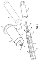
図1は、公知の瀉血針10、針ホルダー12、ならびに針カバー14および16を示す。採血管17が幻影で示されている。瀉血針10は、遠位の針部分20と、近位の針部分22と、係合部分24を備えた中間の針ハブ23とを含む。係合部分24は、瀉血針10を針ホルダー12に接続することを容易にするように提供される。一実施形態において、係合部分は、雄継手24aを含み、雄継手24aは、雌継手または係合部材26と係合するように構成され、係合部材26は、針ホルダー12の遠位端に提供される。あるいは、ねじ、スナップ型コネクタ、その他を含む他の係合構造が使用され得る。下にさらに詳細に記述されるように、エラストマーのシールド28が近位の針部分22を覆い位置決めされ、近位の針部分22をシールする。
FIG. 1 shows a known
針ホルダー12は、実質的に円筒状の本体30を含み、実質的に円筒状の本体30は、係合部材26を含む遠位端および一対のフランジ部材32を含む近位端を有する。フランジ部材32は、医療従事者による採血管17の把持および挿入を容易にする。円筒状の本体30は、採血管17を受け入れるための空洞34(図1A)を画定する。通常、採血管17は、貫通可能ストッパ17aによってシールされ、低圧の空洞17b(図1A)を画定する。ホルダー12の遠位端は、係合部材26を通る開口部36を画定し、開口部36は、近位の針部分22を受け入れる大きさとされる。
Needle holder 12 includes a substantially cylindrical body 30 having a distal end including an engagement member 26 and a proximal end including a pair of
図1Aに示されるように、使用に際して、針10は、係合部分24および係合部材26を介して針ホルダー12の遠位端に固定される。針10が針ホルダー12に固定されると、近位の針部分22は、針ホルダー12の本体30の空洞34内に位置決めされ、エラストマーのシールド28は、近位の針部分22を覆い位置決めされる。次に、貫通可能ストッパ17aを含む採血管17(幻影で示される)が、空洞34内に位置決めされる。採血管17が空洞34の中に挿入されると、近位の針部分22が、ストッパ17aと係合し、シールド28を貫通する。近位の針部分22が、ストッパ40を貫通し、採血管17の空洞17bに入るように、シールド28は下向きに圧縮(図1A)される。遠位の針部分20が患者の静脈38に正しく位置決めされ、採血管17が空洞34内に位置決めされると、血液が、針10を通って採血管17の中に流入するように、通常、採血管17は、真空に維持される。採血管17が針ホルダー12から取り外されると、弾力的なエラストマーのシールド28は、その元の構成に戻り、近位の針部分22を被覆し、近位の針部分22をシールする。
As shown in FIG. 1A, in use, the
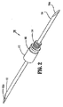
図2および図2Aは、概して100として示されるフラッシュバックチャンバを備えた本開示の瀉血針の一実施形態を示す。針100は、遠位端102と、近位端104と、中央部分106とを含む。遠位端102は、患者の組織を貫通するように構成された尖った端102aを有し、近位端104は、採血管17(図1Aを参照)のストッパ17aを貫通するように構成された尖った端104aを有する。中央部分106は、上に論議されたように、係合部材108を含み、係合部材108は針ホルダー(図1)と係合するように構成される。中央部分106はまた、開口部または穴110と、開口部110を画定する部分の中央部分106の周りに位置決めされた半透明または透明の筐体112とを含む。開口部110は円形として示されているが、他の構成、例えば長方形、正方形、楕円形、細長いスロット39(図5)、その他が想定されている。透明の筐体112は、血液レザバ112aを画定する。通気開口部113は好ましくは、透明の筐体112に形成される。通気開口部113が針100の通気を容易にし、針100を通る血流を可能にする。下に論議されるように、筐体112の通気開口部113は、空気の通過は許すが、例えば血液のような液体の通過は許さない材料によって被覆され得る。
FIGS. 2 and 2A show one embodiment of a phlebotomy needle of the present disclosure with a flashback chamber shown generally as 100. Needle 100 includes a
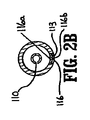
図2Aおよび図2Bを参照して、通気開口部113は、フィルタ116で被覆され得る。フィルタ116は好ましくは、親水性材料の内側層116aと、疎水性材料の外側層116bとを含む。好ましくは、層116aおよび層116bのうちの少なくとも1つは、0.45ミクロンを下回る孔サイズを有する。かかる孔サイズは、空気の通過は可能にするが、バクテリアが筐体112の中に入ることを防止する。
Referring to FIGS. 2A and 2B, vent
図2Cを参照して、代替の実施形態において、フィルタ116は、例えばフラップ弁150のような疎水性逆止弁によって置き換えられ得る。図示のように、フラップ弁150は、筐体112の中に血液が流入し始めると、筐体112から外向きに曲がり、通気開口部113を露出させ、筐体112を通気するように構成される。逆止弁が開いたとき、血液が通気開口部113から出ることを防止するために、疎水性シート152が開口部113を覆い位置決めされる。血液が筐体112の中に流入し始めるのに先立って、フラップ弁150は開口部113をシールし、物質が筐体112の中に入ることを防止する。あるいは、フラップ弁150は、親水性材料の孔サイズが血液成分の通過を遮るサイズである場合は、該親水性材料から形成され得る。
Referring to FIG. 2C, in an alternative embodiment,
針100の遠位端102が患者の静脈内に正しく位置決めされたとき、すなわち、血液が針100を通って流れ、空気が通気されて、血液が開口部110を通ってレザバ112aの中に入るとき、透明の筐体112は、医療実施者が針100を通る血流を可視化することを可能にする。これによって、医療実施者は、針100の遠位端102が、血液を抜き取るために患者の静脈内に正しく位置決めされたことを確認することができる。これは、患者から血液を抜き取ろうと試みる医療実施者に対して、特に瀉血針によって患者から血液を抜き取ることについて限られた経験しか有しないような実施者に対して大きな利益を提供する。
When the
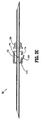
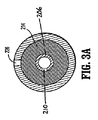
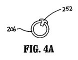
図3は、概して200として示されるフラッシュバックチャンバを備えた本開示の通気型瀉血針の代替の実施形態を示す。針200は、下に記述されるとおりを除いて、針100と実質的に同様である。針200は、遠位端202と、近位端204と、中央部分206とを含む。遠位端202は、患者の組織を貫通するように構成された尖った端202aを有し、近位端204は、採血管(図1Aを参照)のストッパを貫通するように構成された尖った端204aを有する。中央部分206は、開口部または穴210と係合部材212aとを含む。材料214は、穴210を覆い位置決めされている。医療従事者が針200を通る血流を容易に識別し得るように、材料214は、材料の中に血液を毛管作用で吸い込む親水性の材料であり得る。針200の通気を容易にするために、材料214は、空気に対しては透過性があるが、例えば血液のように液体に対しては透過性がない親水性材料であり得る。一実施形態において、親水性材料は、血液と接触したとき、色が変わるタイプのものであり得る。材料は、カラー250(図3)またはプラグ252(図4)の形であり得る。さらに、材料は、透明の筐体もしくはハブ212内に位置決めされ得るか、または代替的に、いかなる筐体もなく開口部210に隣接して位置決めされ得る。代替の実施形態において、材料は、空気は通すが血液は通さない疎水性の材料である。通気開口部226は筐体212に提供され得、筐体の通気を容易にし得ることに留意される。通気孔は、筐体212における開口部の形であり得、該開口部は、血液が入ると筐体212から空気が流れ出ることを可能にする。
FIG. 3 shows an alternative embodiment of the vented phlebotomy needle of the present disclosure with a flashback chamber shown generally as 200. Needle 200 is substantially similar to needle 100, except as described below. Needle 200 includes a
図3および図3Aでさらに示される代替の実施形態において、材料214は、膨張可能な材料で形成され得、該膨張可能な材料が血液と接触する前に、空気が通気開口部226を通ることを可能にするる。材料214は、血液と接触すると膨張し得、通気開口部226を閉じ得る。
In the alternative embodiment further illustrated in FIGS. 3 and 3A, the
本明細書において、親水性材料および疎水性材料のみが開示されたが、血液の通過を防止しながら空気の通過を容易にし、血流の表示を提供する他の材料が、本開示の瀉血針に対して使用され得る。材料は、本明細書に開示されていない他の構成を有し得る。例えば、材料は、開口部を被覆するパッドを画定し得る。 Although only hydrophilic and hydrophobic materials are disclosed herein, other materials that facilitate the passage of air while preventing the passage of blood and provide an indication of blood flow are the hemorrhagic needles of the present disclosure. Can be used for The material may have other configurations not disclosed herein. For example, the material may define a pad that covers the opening.
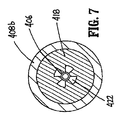
図6および図7は、概してデバイス398として示されるフラッシュバックチャンバを備えた本開示の瀉血針の別の実施形態を示す。瀉血針398は、針400と段付き筐体408とを含む。針400は、遠位端402と、近位端404と、中央部分406とを含む。遠位端402は、患者の組織を貫通するように構成された尖った端402aを有し、近位端404は、採血管(図示されず)のストッパ(図示されず)を貫通するように構成された尖った端404aを有する。
6 and 7 illustrate another embodiment of a phlebotomy needle of the present disclosure with a flashback chamber shown generally as
段付き筐体408は、遠位部分408aおよびより大きな直径の近位部分408bを有する。段付き筐体408は、中央部分406で支持されている。遠位部分408aは、針の中央部分406を受け入れる大きさとされた通し穴412を画定する。遠位部分408aは、例えば接着剤410を使用して、針400にシールされ、固定される。あるいは、他の公知の技術、例えばクリンプ加工、クランプ、ねじ、溶接その他が使用され得、針400を筐体408に固定し得る。近位部分408bは、透明の材料または半透明の材料で形成され、筐体408の近位部分408b内の可視化を容易にする。近位部分408bはまた、通し穴414を画定し、通し穴414は通し穴412と連通するが、通し穴412よりも直径が大きい。近位部分408bは、部分408bと針400の近位端404との間に環状のリセス416を画定する。リセス416は、親水性材料418および内側の縦溝のある部材420を受け入れるような大きさとされる。内側の縦溝のある部材420が、針400の近位端404の周りに位置決めされ、親水性材料418と連通する複数のチャンネル422を画定する。通気開口部409は、筐体408を通して提供される。
The stepped
エラストマーのシールド428は、針400の近位端404を覆い位置決めされる。上に論議されたように、エラストマーのシールド428は弾力的であり得、針400の近位端404が採血管(図示されず)に接続されていないとき、針400の近位端404をシールするように機能する。エラストマーのシールド428は、閉じた近位端428aと開いた遠位端428bとを含む。開いた遠位端428bは環状のフランジ430を含み、環状のフランジ430は、筐体408のリセス416内で材料418に隣接して位置決めされる。筐体408の近位部分408bは、内向きに延びる環状のリブ432を含み、内向きに延びる環状のリブ432は、エラストマーのシールド428のフランジ430と係合し、シールド428の遠位端428bを筐体408のリセス416内に保持するように位置決めされる。矢印434によって示されるように、流路436は、エラストマーのシールド428と針400の近位端404との間に画定される。流路436は、針400の近位端404から縦溝のある部材420の縦溝のあるチャンネル422の中に血液を導き、親水性材料418と接触させる。使用に際して、血液が材料418と接触すると、材料418は、筐体408の近位部分408bを通して目視可能となる血流の可視表示を提供する。
An
フィルタ116と共に画定された(図2A〜図2B)、フィルタ252と共に画定された(図4〜図4A)、もしくはフィルタ39と共に画定された(図5)、または逆止弁150と共に画定された(図2C)通気開口部113、ならびに開口部226(図3〜図3A)および開口部409(図6)はすべて、受動通気開口部として記述され得、該受動通気開口部は、針カニューレ内において大気圧よりも大きな圧力の気体が大気中に自動的に漏れることを可能にする。これらの受動通気開口部は、本発明によるデバイスのユーザによるいかなる行動も必要としない。
2A-2B, with filter 252 (FIGS. 4-4A), or with filter 39 (FIG. 5), or with check valve 150 (FIG. 2A-2B). FIG. 2C)
本明細書に開示された実施形態には、様々な変更がなされ得ることは理解される。したがって、上述は、限定するものとして解釈されるべきではなく、好ましい実施形態の単なる例示として解釈されるべきである。当業者は、本明細書に添付された請求項の範囲および精神内で他の変更に想到する。 It will be understood that various modifications may be made to the embodiments disclosed herein. Accordingly, the above should not be construed as limiting, but merely as exemplification of the preferred embodiments. Those skilled in the art will envision other modifications within the scope and spirit of the claims appended hereto.
Claims (22)
組織を貫通するように構成された尖った遠位端を有する遠位の針部分と、
採血管のストッパを貫通するように構成された尖った近位端を有する近位の針部分と、
開口部を画定する中央の針部分であって、該遠位の針部分、該近位の針部分および該中央の針部分は、該開口部と連通する流体チャンネルを画定する、中央の針部分と、
該開口部に隣接して位置決めされた材料であって、空気が該開口部を通って該流体チャンネルを出ることを可能にし、一方、血液の通過を防止するタイプのものであり、血流の可視表示をさらに可能にする、材料と
を備えている、瀉血針。 Hemorrhoid needle,
A distal needle portion having a pointed distal end configured to penetrate tissue;
A proximal needle portion having a pointed proximal end configured to penetrate a blood collection stopper;
A central needle portion defining an opening, the distal needle portion, the proximal needle portion and the central needle portion defining a fluid channel in communication with the opening When,
A material positioned adjacent to the opening to allow air to exit the fluid channel through the opening, while preventing the passage of blood, of the blood flow A blood-sustaining needle, equipped with materials and to further enable visual display.
組織を貫通するように構成された尖った遠位端を有する遠位の針部分と、
採血管のストッパを貫通するように構成された尖った近位端を有する近位の針部分と、
開口部を画定する中央の針部分であって、該遠位の針部分、該近位の針部分および該中央の針部分は、該開口部と連通する流体チャンネルを画定する、中央の針部分と、
該開口部に隣接して位置決めされた疎水性材料であって、空気が該開口部を通って該流体チャンネルを出ることを可能にし、一方、血液の通過を防止するタイプのものであり、血流の可視表示をさらに可能にする、疎水性材料と、
該開口部の周りに位置決めされた透明の筐体と、
該瀉血針で支持された係合構造であって、針ホルダーと係合するように構成された、係合構造と
を備えている、瀉血針。 Hemorrhoid needle,
A distal needle portion having a pointed distal end configured to penetrate tissue;
A proximal needle portion having a pointed proximal end configured to penetrate a blood collection stopper;
A central needle portion defining an opening, the distal needle portion, the proximal needle portion and the central needle portion defining a fluid channel in communication with the opening When,
A hydrophobic material positioned adjacent to the opening to allow air to exit the fluid channel through the opening while preventing the passage of blood, blood Hydrophobic materials, which further allow visual indication of the flow
A transparent housing positioned around the opening;
An engagement structure supported by the hemorrhage needle, comprising: an engagement structure configured to engage with the needle holder.
組織を貫通するように構成された尖った遠位端を有する遠位の針部分と、
採血管のストッパを貫通するように構成された尖った近位端を有する近位の針部分と、
開口部を画定する中央の針部分であって、該遠位の針部分、該近位の針部分および該中央の針部分は、該開口部と連通する流体チャンネルを画定する、中央の針部分と、
該開口部に隣接して位置決めされた親水性毛管作用材料であって、空気が該開口部を通って該流体チャンネルを出ることを可能にし、一方、血液の通過を防止するタイプのものであり、血流の可視表示をさらに可能にする、親水性毛管作用材料と、
該開口部の周りに位置決めされた透明の筐体と、
該瀉血針で支持された係合構造であって、針ホルダーと係合するように構成された、係合構造と
を備えている、瀉血針。 Hemorrhoid needle,
A distal needle portion having a pointed distal end configured to penetrate tissue;
A proximal needle portion having a pointed proximal end configured to penetrate a blood collection stopper;
A central needle portion defining an opening, the distal needle portion, the proximal needle portion and the central needle portion defining a fluid channel in communication with the opening When,
A hydrophilic capillary action material positioned adjacent to the opening, of the type which allows air to exit the fluid channel through the opening while preventing the passage of blood. Hydrophilic capillary action material, which further allows visual indication of blood flow,
A transparent housing positioned around the opening;
An engagement structure supported by the hemorrhage needle, comprising: an engagement structure configured to engage with the needle holder.
針であって、組織を貫通するように構成された尖った遠位端を有する遠位の針部分と、採血管のストッパを貫通するように構成された尖った近位端を有する近位の針部分とを含み、該遠位の針部分および該近位の針部分は、流体チャンネルを画定する、針と、
該針で支持された筐体であって、受動通気孔を含み、該筐体の血液を可視化するための観察領域を画定する、筐体と
を備えている、瀉血針。 A hemopneumatic needle, wherein
A needle having a distal needle portion having a pointed distal end configured to penetrate tissue and a proximal end having a pointed proximal end configured to penetrate a blood collection stopper. A needle including a needle portion, the distal needle portion and the proximal needle portion defining a fluid channel;
A needle-supported housing, comprising: a passive vent, wherein the housing defines an observation area for visualizing blood of the housing;
Applications Claiming Priority (2)
| Application Number | Priority Date | Filing Date | Title |
|---|---|---|---|
| US87793706P | 2006-12-29 | 2006-12-29 | |
| PCT/US2007/026111 WO2008085393A1 (en) | 2006-12-29 | 2007-12-20 | Vented phlebotomy needle with flashback chamber |
Related Child Applications (1)
| Application Number | Title | Priority Date | Filing Date |
|---|---|---|---|
| JP2013147592A Division JP2013240628A (en) | 2006-12-29 | 2013-07-16 | Vented phlebotomy needle with flashback chamber |
Publications (2)
| Publication Number | Publication Date |
|---|---|
| JP2010514501A true JP2010514501A (en) | 2010-05-06 |
| JP2010514501A5 JP2010514501A5 (en) | 2011-02-03 |
Family
ID=39594900
Family Applications (2)
| Application Number | Title | Priority Date | Filing Date |
|---|---|---|---|
| JP2009544044A Withdrawn JP2010514501A (en) | 2006-12-29 | 2007-12-20 | Vented phlebotomy needle with flashback chamber |
| JP2013147592A Pending JP2013240628A (en) | 2006-12-29 | 2013-07-16 | Vented phlebotomy needle with flashback chamber |
Family Applications After (1)
| Application Number | Title | Priority Date | Filing Date |
|---|---|---|---|
| JP2013147592A Pending JP2013240628A (en) | 2006-12-29 | 2013-07-16 | Vented phlebotomy needle with flashback chamber |
Country Status (6)
| Country | Link |
|---|---|
| US (1) | US20080167577A1 (en) |
| EP (1) | EP2097123B1 (en) |
| JP (2) | JP2010514501A (en) |
| CA (1) | CA2672141A1 (en) |
| MX (1) | MX2009006857A (en) |
| WO (1) | WO2008085393A1 (en) |
Cited By (1)
| Publication number | Priority date | Publication date | Assignee | Title |
|---|---|---|---|---|
| JP2021514242A (en) * | 2018-02-27 | 2021-06-10 | イー−ファ メディテック インコーポレイテッド | Chemical supply control device and injection solution injection device equipped with it |
Families Citing this family (34)
| Publication number | Priority date | Publication date | Assignee | Title |
|---|---|---|---|---|
| KR101009447B1 (en) * | 2007-11-12 | 2011-01-19 | 바디텍메드 주식회사 | Device for sampling and preprocessing biological fluids and method thereof |
| CN102596033B (en) * | 2009-09-09 | 2014-12-31 | 保利医疗用品有限公司 | Blood collection device |
| JP2011212182A (en) * | 2010-03-31 | 2011-10-27 | Terumo Corp | Prefilled syringe |
| GB2487899A (en) | 2011-02-01 | 2012-08-15 | Olberon Ltd | Needle holder with grip means |
| ITRM20110338A1 (en) * | 2011-06-27 | 2012-12-28 | Mauro Pepe | HOLDER WITH COLLECTION CHAMBER FOR WITHDRAWAL EMATICS. |
| US9022950B2 (en) * | 2012-05-30 | 2015-05-05 | Magnolia Medical Technologies, Inc. | Fluid diversion mechanism for bodily-fluid sampling |
| US9060724B2 (en) * | 2012-05-30 | 2015-06-23 | Magnolia Medical Technologies, Inc. | Fluid diversion mechanism for bodily-fluid sampling |
| US9204864B2 (en) | 2012-08-01 | 2015-12-08 | Magnolia Medical Technologies, Inc. | Fluid diversion mechanism for bodily-fluid sampling |
| EP2887991B1 (en) | 2012-08-21 | 2022-11-02 | Optomeditech Oy | Intravascular catheter assembly |
| WO2014029421A1 (en) | 2012-08-21 | 2014-02-27 | Optomeditech Oy | Blood collection needle assembly having a light source |
| ES2878047T3 (en) | 2012-10-11 | 2021-11-18 | Magnolia Medical Technologies Inc | System for administering a fluid to a patient with reduced contamination |
| CN104955392B (en) | 2012-11-30 | 2018-11-02 | 木兰医药技术股份有限公司 | The transfer device based on syringe for body fluid sampling |
| US10772548B2 (en) | 2012-12-04 | 2020-09-15 | Magnolia Medical Technologies, Inc. | Sterile bodily-fluid collection device and methods |
| IL303591A (en) | 2012-12-04 | 2023-08-01 | Magnolia Medical Technologies Inc | Sterile bodily-fluid collection device and methods |
| WO2016075574A1 (en) | 2014-11-12 | 2016-05-19 | Poly Medicure Limited | Needle assembly with flashback chamber for collecting blood or other liquid samples |
| EP3769681B1 (en) | 2015-06-12 | 2022-03-02 | Magnolia Medical Technologies, Inc. | Bodily-fluid sampling and transfer device |
| US10010282B2 (en) * | 2015-07-24 | 2018-07-03 | Kurin, Inc. | Blood sample optimization system and blood contaminant sequestration device and method |
| US10639455B2 (en) * | 2015-10-28 | 2020-05-05 | Becton, Dickinson And Company | Closed IV access device with paddle grip needle hub and flash chamber |
| US10525237B2 (en) | 2015-10-28 | 2020-01-07 | Becton, Dickinson And Company | Ergonomic IV systems and methods |
| US10549072B2 (en) | 2015-10-28 | 2020-02-04 | Becton, Dickinson And Company | Integrated catheter with independent fluid paths |
| US10245416B2 (en) | 2015-10-28 | 2019-04-02 | Becton, Dickinson And Company | Intravenous catheter device with integrated extension tube |
| US10814106B2 (en) | 2015-10-28 | 2020-10-27 | Becton, Dickinson And Company | Soft push tabs for catheter adapter |
| US10744305B2 (en) | 2015-10-28 | 2020-08-18 | Becton, Dickinson And Company | Ergonomic IV systems and methods |
| US10238852B2 (en) | 2016-10-05 | 2019-03-26 | Becton, Dickinson And Company | Septum housing |
| USD819802S1 (en) | 2016-10-05 | 2018-06-05 | Becton, Dickinson And Company | Catheter adapter |
| USD837368S1 (en) | 2016-10-05 | 2019-01-01 | Becton, Dickinson And Company | Catheter adapter grip |
| USD835262S1 (en) | 2016-10-05 | 2018-12-04 | Becton, Dickinson And Company | Intravenous catheter assembly |
| JP7003139B2 (en) * | 2016-12-27 | 2022-01-20 | クリン インコーポレイテッド | Blood isolation device and blood isolation and sampling system |
| US11617525B2 (en) * | 2017-02-10 | 2023-04-04 | Kurin, Inc. | Blood contaminant sequestration device with passive fluid control junction |
| US10827964B2 (en) * | 2017-02-10 | 2020-11-10 | Kurin, Inc. | Blood contaminant sequestration device with one-way air valve and air-permeable blood barrier with closure mechanism |
| JP7204742B2 (en) | 2017-09-12 | 2023-01-16 | マグノリア メディカル テクノロジーズ,インコーポレイテッド | FLUID CONTROL DEVICE AND METHOD OF USING FLUID CONTROL DEVICE |
| EP3721086A4 (en) | 2017-12-07 | 2021-11-10 | Magnolia Medical Technologies, Inc. | Fluid control devices and methods of using the same |
| AU2020218544A1 (en) | 2019-02-08 | 2021-09-16 | Magnolia Medical Technologies, Inc. | Devices and methods for bodily fluid collection and distribution |
| CN113784793B (en) | 2019-03-11 | 2023-09-19 | 木兰医药技术股份有限公司 | Fluid control device and method of using the same |
Citations (3)
| Publication number | Priority date | Publication date | Assignee | Title |
|---|---|---|---|---|
| US4416290A (en) * | 1982-08-30 | 1983-11-22 | Becton Dickinson And Company | Multiple sample needle assembly with vein indication |
| US5303713A (en) * | 1990-09-26 | 1994-04-19 | Terumo Kabushiki Kaisha | Blood collecting needle |
| JPH07379A (en) * | 1993-02-22 | 1995-01-06 | Issei Suzuki | Vacuum blood collecting needle |
Family Cites Families (28)
| Publication number | Priority date | Publication date | Assignee | Title |
|---|---|---|---|---|
| US3063451A (en) * | 1959-09-28 | 1962-11-13 | Arthur J Kowalk | Self-venting type needle |
| US3500821A (en) * | 1967-12-05 | 1970-03-17 | Asper Vac Corp | Multiple blood sampling apparatus with aspiration means |
| CA1009110A (en) * | 1971-04-30 | 1977-04-26 | Abbott Laboratories | Blood collecting assembly |
| US3916892A (en) * | 1974-04-29 | 1975-11-04 | Haemonetics Corp | Phlebotomy needle system incorporating means to add anticoagulant and wash liquid |
| US4106497A (en) * | 1977-02-04 | 1978-08-15 | Becton, Dickinson And Company | Multiple sample needle assembly with indicator means |
| US4280496A (en) * | 1979-02-16 | 1981-07-28 | Baxter Travenol Laboratories, Inc. | Phlebotomy needle assembly |
| US4365630A (en) * | 1981-03-10 | 1982-12-28 | Mcfarlane Richard H | Flashback chamber for catheter |
| US4904242A (en) * | 1987-04-29 | 1990-02-27 | Kulli John C | Phlebotomy set with safety retracting needle |
| US4947863A (en) * | 1988-08-30 | 1990-08-14 | Habley Medical Technology Corporation | Energy-dissipating, safety blood collection tube holder |
| US4971068A (en) * | 1989-07-07 | 1990-11-20 | Bio-Plexus, Inc. | Blood vessel locating needle assembly with thermochromic indicator |
| US5030207A (en) * | 1990-11-02 | 1991-07-09 | Becton, Dickinson And Company | Instantaneous vein entry indicator for intravenous needle |
| US5178157A (en) * | 1992-01-14 | 1993-01-12 | Fanlo Ramon G | Phlebotomy device and method of use thereof |
| US5314410A (en) * | 1992-02-10 | 1994-05-24 | Marks Ronald L | Entry indicator device for arterial or intravenous needle |
| US5401250A (en) * | 1992-10-05 | 1995-03-28 | Shields; Jack W. | Tethered conical shield for phlebotomy needles |
| US5450856A (en) * | 1994-04-25 | 1995-09-19 | Norris; Wendal A. | Phlebotomy needle attachable to a vacuum container with a vent to preclude blood flashback |
| US5613500A (en) * | 1995-02-21 | 1997-03-25 | Bishop; Steve | Retractable phlebotomy needle |
| US5782820A (en) * | 1996-02-12 | 1998-07-21 | Roland; Patricia D. | Disposable seal for vacutainer holder |
| US6063040A (en) * | 1998-01-16 | 2000-05-16 | Specialized Health Products, Inc. | Self retracting needle apparatus and method for phlebotomy |
| JP2000166903A (en) * | 1998-12-01 | 2000-06-20 | Issei Suzuki | Vacuum blood drawing needle |
| JP3723972B2 (en) * | 2000-04-19 | 2005-12-07 | ニプロ株式会社 | Blood collection needle |
| WO2002028458A1 (en) * | 2000-10-06 | 2002-04-11 | Maxwell Edmund Whisson | Body heat actuated parenteral device |
| WO2002068020A2 (en) * | 2001-02-28 | 2002-09-06 | Futura Medical Technologies, Inc. | Safety-sheathed phlebotomy needle holder |
| EP1555037B1 (en) * | 2001-11-13 | 2012-02-29 | Becton, Dickinson and Company | Shieldable needle assembly |
| US7226432B2 (en) * | 2004-05-03 | 2007-06-05 | Clear View Patient Safety Products, Llc | Blood drawing device |
| US20050273019A1 (en) * | 2004-06-02 | 2005-12-08 | Becton, Dickinson And Company | Blood collection set with venting mechanism |
| US20050283093A1 (en) * | 2004-06-02 | 2005-12-22 | Becton, Dickinson And Company | Flashback blood collection needle |
| MX340160B (en) * | 2007-03-07 | 2016-06-29 | Becton Dickinson And Company * | Safety blood collection assembly with indicator. |
| US7918805B2 (en) * | 2007-09-27 | 2011-04-05 | Tyco Healthcare Group Lp | Phlebotomy needle with shape memory alloy flashback sensor |
-
2007
- 2007-12-20 US US12/004,278 patent/US20080167577A1/en not_active Abandoned
- 2007-12-20 JP JP2009544044A patent/JP2010514501A/en not_active Withdrawn
- 2007-12-20 EP EP07863189A patent/EP2097123B1/en not_active Not-in-force
- 2007-12-20 WO PCT/US2007/026111 patent/WO2008085393A1/en active Application Filing
- 2007-12-20 CA CA002672141A patent/CA2672141A1/en not_active Abandoned
- 2007-12-20 MX MX2009006857A patent/MX2009006857A/en active IP Right Grant
-
2013
- 2013-07-16 JP JP2013147592A patent/JP2013240628A/en active Pending
Patent Citations (3)
| Publication number | Priority date | Publication date | Assignee | Title |
|---|---|---|---|---|
| US4416290A (en) * | 1982-08-30 | 1983-11-22 | Becton Dickinson And Company | Multiple sample needle assembly with vein indication |
| US5303713A (en) * | 1990-09-26 | 1994-04-19 | Terumo Kabushiki Kaisha | Blood collecting needle |
| JPH07379A (en) * | 1993-02-22 | 1995-01-06 | Issei Suzuki | Vacuum blood collecting needle |
Cited By (2)
| Publication number | Priority date | Publication date | Assignee | Title |
|---|---|---|---|---|
| JP2021514242A (en) * | 2018-02-27 | 2021-06-10 | イー−ファ メディテック インコーポレイテッド | Chemical supply control device and injection solution injection device equipped with it |
| JP7089302B2 (en) | 2018-02-27 | 2022-06-22 | イー-ファ メディテック インコーポレイテッド | Chemical supply control device and injection solution injection device equipped with it |
Also Published As
| Publication number | Publication date |
|---|---|
| WO2008085393A1 (en) | 2008-07-17 |
| JP2013240628A (en) | 2013-12-05 |
| EP2097123A1 (en) | 2009-09-09 |
| MX2009006857A (en) | 2009-07-07 |
| CA2672141A1 (en) | 2008-07-17 |
| EP2097123A4 (en) | 2010-09-15 |
| EP2097123B1 (en) | 2012-12-05 |
| US20080167577A1 (en) | 2008-07-10 |
Similar Documents
| Publication | Publication Date | Title |
|---|---|---|
| JP2010514501A (en) | Vented phlebotomy needle with flashback chamber | |
| JP5325789B2 (en) | Extravascular ventilation system | |
| US8162896B2 (en) | Flashback blood collection needle | |
| EP1254680B1 (en) | Flashback blood collection needle | |
| US7488297B2 (en) | Blood collecting devices | |
| EP0049591B1 (en) | Single sample needle with vein entry indicator | |
| JP4302401B2 (en) | Chest ventilation kit | |
| AU2010293874B2 (en) | Blood collection device | |
| JP3448293B2 (en) | Connection device having a seal provided with a slit in advance | |
| US10813579B2 (en) | Blood collection device | |
| KR20050095602A (en) | Flashback blood collection needle | |
| BR112013001050B1 (en) | EXTRAVASCULAR SYSTEM | |
| JPS6219170B2 (en) | ||
| JP2011525124A (en) | Diagnostic sample collection system | |
| JP2008538185A (en) | Medical device and method of use thereof | |
| US20070088229A1 (en) | Needle assembly for a blood sampling device | |
| BR112016024175B1 (en) | NEEDLE ASSEMBLY TO COLLECT BLOOD OR OTHER LIQUID SAMPLES | |
| JPH08150134A (en) | Blood-gathering needle | |
| AU2014200804B2 (en) | Blood collection device | |
| CA2832094C (en) | Flashback blood collection needle | |
| AU2005246999B2 (en) | Flashback blood collection needle | |
| JP2004283364A (en) | Blood collecting needle | |
| AU2014200917A1 (en) | Flashback blood collection needle |
Legal Events
| Date | Code | Title | Description |
|---|---|---|---|
| A521 | Request for written amendment filed |
Free format text: JAPANESE INTERMEDIATE CODE: A523 Effective date: 20101208 |
|
| A621 | Written request for application examination |
Free format text: JAPANESE INTERMEDIATE CODE: A621 Effective date: 20101208 |
|
| A521 | Request for written amendment filed |
Free format text: JAPANESE INTERMEDIATE CODE: A523 Effective date: 20111125 |
|
| A977 | Report on retrieval |
Free format text: JAPANESE INTERMEDIATE CODE: A971007 Effective date: 20120629 |
|
| A131 | Notification of reasons for refusal |
Free format text: JAPANESE INTERMEDIATE CODE: A131 Effective date: 20120801 |
|
| A521 | Request for written amendment filed |
Free format text: JAPANESE INTERMEDIATE CODE: A523 Effective date: 20121017 |
|
| A02 | Decision of refusal |
Free format text: JAPANESE INTERMEDIATE CODE: A02 Effective date: 20130401 |
|
| A521 | Request for written amendment filed |
Free format text: JAPANESE INTERMEDIATE CODE: A523 Effective date: 20130716 |
|
| A911 | Transfer to examiner for re-examination before appeal (zenchi) |
Free format text: JAPANESE INTERMEDIATE CODE: A911 Effective date: 20130723 |
|
| A912 | Re-examination (zenchi) completed and case transferred to appeal board |
Free format text: JAPANESE INTERMEDIATE CODE: A912 Effective date: 20131004 |
|
| A601 | Written request for extension of time |
Free format text: JAPANESE INTERMEDIATE CODE: A601 Effective date: 20140108 |
|
| A602 | Written permission of extension of time |
Free format text: JAPANESE INTERMEDIATE CODE: A602 Effective date: 20140114 |
|
| A761 | Written withdrawal of application |
Free format text: JAPANESE INTERMEDIATE CODE: A761 Effective date: 20140121 |