JP2010510419A - Hook-loop attachment of solar panel to roof membrane - Google Patents
Hook-loop attachment of solar panel to roof membrane Download PDFInfo
- Publication number
- JP2010510419A JP2010510419A JP2009538412A JP2009538412A JP2010510419A JP 2010510419 A JP2010510419 A JP 2010510419A JP 2009538412 A JP2009538412 A JP 2009538412A JP 2009538412 A JP2009538412 A JP 2009538412A JP 2010510419 A JP2010510419 A JP 2010510419A
- Authority
- JP
- Japan
- Prior art keywords
- fastener
- roof
- paver
- pad
- generation system
- Prior art date
- Legal status (The legal status is an assumption and is not a legal conclusion. Google has not performed a legal analysis and makes no representation as to the accuracy of the status listed.)
- Pending
Links
- 239000012528 membrane Substances 0.000 title claims description 33
- 238000009434 installation Methods 0.000 claims description 16
- 239000000853 adhesive Substances 0.000 claims description 14
- 230000001070 adhesive effect Effects 0.000 claims description 14
- 239000002390 adhesive tape Substances 0.000 claims description 3
- 230000002093 peripheral effect Effects 0.000 claims description 3
- 239000000463 material Substances 0.000 description 11
- 238000000034 method Methods 0.000 description 9
- 230000008878 coupling Effects 0.000 description 6
- 238000010168 coupling process Methods 0.000 description 6
- 238000005859 coupling reaction Methods 0.000 description 6
- 230000006378 damage Effects 0.000 description 5
- 239000010426 asphalt Substances 0.000 description 3
- 238000009413 insulation Methods 0.000 description 3
- 238000004519 manufacturing process Methods 0.000 description 3
- 229920002943 EPDM rubber Polymers 0.000 description 2
- 238000005553 drilling Methods 0.000 description 2
- 230000007246 mechanism Effects 0.000 description 2
- 230000001105 regulatory effect Effects 0.000 description 2
- 239000004065 semiconductor Substances 0.000 description 2
- 235000012431 wafers Nutrition 0.000 description 2
- 230000004888 barrier function Effects 0.000 description 1
- 239000004568 cement Substances 0.000 description 1
- 238000004140 cleaning Methods 0.000 description 1
- 238000011109 contamination Methods 0.000 description 1
- 230000000593 degrading effect Effects 0.000 description 1
- 239000000428 dust Substances 0.000 description 1
- 230000000694 effects Effects 0.000 description 1
- 229920001971 elastomer Polymers 0.000 description 1
- 230000005611 electricity Effects 0.000 description 1
- 239000011521 glass Substances 0.000 description 1
- 239000000383 hazardous chemical Substances 0.000 description 1
- 238000007689 inspection Methods 0.000 description 1
- 230000013011 mating Effects 0.000 description 1
- 238000005259 measurement Methods 0.000 description 1
- 238000012986 modification Methods 0.000 description 1
- 230000004048 modification Effects 0.000 description 1
- 229920003023 plastic Polymers 0.000 description 1
- 229920000642 polymer Polymers 0.000 description 1
- 230000037452 priming Effects 0.000 description 1
- 230000008569 process Effects 0.000 description 1
- 230000002787 reinforcement Effects 0.000 description 1
- 230000008439 repair process Effects 0.000 description 1
- 239000011347 resin Substances 0.000 description 1
- 229920005989 resin Polymers 0.000 description 1
- 230000003068 static effect Effects 0.000 description 1
- 239000000126 substance Substances 0.000 description 1
- 230000003685 thermal hair damage Effects 0.000 description 1
Images


Classifications
-
- F—MECHANICAL ENGINEERING; LIGHTING; HEATING; WEAPONS; BLASTING
- F24—HEATING; RANGES; VENTILATING
- F24S—SOLAR HEAT COLLECTORS; SOLAR HEAT SYSTEMS
- F24S25/00—Arrangement of stationary mountings or supports for solar heat collector modules
- F24S25/60—Fixation means, e.g. fasteners, specially adapted for supporting solar heat collector modules
- F24S25/61—Fixation means, e.g. fasteners, specially adapted for supporting solar heat collector modules for fixing to the ground or to building structures
-
- H—ELECTRICITY
- H02—GENERATION; CONVERSION OR DISTRIBUTION OF ELECTRIC POWER
- H02S—GENERATION OF ELECTRIC POWER BY CONVERSION OF INFRARED RADIATION, VISIBLE LIGHT OR ULTRAVIOLET LIGHT, e.g. USING PHOTOVOLTAIC [PV] MODULES
- H02S10/00—PV power plants; Combinations of PV energy systems with other systems for the generation of electric power
-
- E—FIXED CONSTRUCTIONS
- E04—BUILDING
- E04D—ROOF COVERINGS; SKY-LIGHTS; GUTTERS; ROOF-WORKING TOOLS
- E04D11/00—Roof covering, as far as not restricted to features covered by only one of groups E04D1/00 - E04D9/00; Roof covering in ways not provided for by groups E04D1/00 - E04D9/00, e.g. built-up roofs, elevated load-supporting roof coverings
-
- E—FIXED CONSTRUCTIONS
- E04—BUILDING
- E04D—ROOF COVERINGS; SKY-LIGHTS; GUTTERS; ROOF-WORKING TOOLS
- E04D3/00—Roof covering by making use of flat or curved slabs or stiff sheets
- E04D3/02—Roof covering by making use of flat or curved slabs or stiff sheets of plane slabs, slates, or sheets, or in which the cross-section is unimportant
-
- H—ELECTRICITY
- H02—GENERATION; CONVERSION OR DISTRIBUTION OF ELECTRIC POWER
- H02S—GENERATION OF ELECTRIC POWER BY CONVERSION OF INFRARED RADIATION, VISIBLE LIGHT OR ULTRAVIOLET LIGHT, e.g. USING PHOTOVOLTAIC [PV] MODULES
- H02S20/00—Supporting structures for PV modules
- H02S20/20—Supporting structures directly fixed to an immovable object
- H02S20/22—Supporting structures directly fixed to an immovable object specially adapted for buildings
- H02S20/23—Supporting structures directly fixed to an immovable object specially adapted for buildings specially adapted for roof structures
- H02S20/24—Supporting structures directly fixed to an immovable object specially adapted for buildings specially adapted for roof structures specially adapted for flat roofs
-
- F—MECHANICAL ENGINEERING; LIGHTING; HEATING; WEAPONS; BLASTING
- F24—HEATING; RANGES; VENTILATING
- F24S—SOLAR HEAT COLLECTORS; SOLAR HEAT SYSTEMS
- F24S25/00—Arrangement of stationary mountings or supports for solar heat collector modules
- F24S25/60—Fixation means, e.g. fasteners, specially adapted for supporting solar heat collector modules
- F24S2025/6001—Fixation means, e.g. fasteners, specially adapted for supporting solar heat collector modules by using hook and loop-type fasteners
-
- F—MECHANICAL ENGINEERING; LIGHTING; HEATING; WEAPONS; BLASTING
- F24—HEATING; RANGES; VENTILATING
- F24S—SOLAR HEAT COLLECTORS; SOLAR HEAT SYSTEMS
- F24S25/00—Arrangement of stationary mountings or supports for solar heat collector modules
- F24S25/60—Fixation means, e.g. fasteners, specially adapted for supporting solar heat collector modules
- F24S2025/601—Fixation means, e.g. fasteners, specially adapted for supporting solar heat collector modules by bonding, e.g. by using adhesives
-
- F—MECHANICAL ENGINEERING; LIGHTING; HEATING; WEAPONS; BLASTING
- F24—HEATING; RANGES; VENTILATING
- F24S—SOLAR HEAT COLLECTORS; SOLAR HEAT SYSTEMS
- F24S25/00—Arrangement of stationary mountings or supports for solar heat collector modules
-
- Y—GENERAL TAGGING OF NEW TECHNOLOGICAL DEVELOPMENTS; GENERAL TAGGING OF CROSS-SECTIONAL TECHNOLOGIES SPANNING OVER SEVERAL SECTIONS OF THE IPC; TECHNICAL SUBJECTS COVERED BY FORMER USPC CROSS-REFERENCE ART COLLECTIONS [XRACs] AND DIGESTS
- Y02—TECHNOLOGIES OR APPLICATIONS FOR MITIGATION OR ADAPTATION AGAINST CLIMATE CHANGE
- Y02B—CLIMATE CHANGE MITIGATION TECHNOLOGIES RELATED TO BUILDINGS, e.g. HOUSING, HOUSE APPLIANCES OR RELATED END-USER APPLICATIONS
- Y02B10/00—Integration of renewable energy sources in buildings
- Y02B10/10—Photovoltaic [PV]
-
- Y—GENERAL TAGGING OF NEW TECHNOLOGICAL DEVELOPMENTS; GENERAL TAGGING OF CROSS-SECTIONAL TECHNOLOGIES SPANNING OVER SEVERAL SECTIONS OF THE IPC; TECHNICAL SUBJECTS COVERED BY FORMER USPC CROSS-REFERENCE ART COLLECTIONS [XRACs] AND DIGESTS
- Y02—TECHNOLOGIES OR APPLICATIONS FOR MITIGATION OR ADAPTATION AGAINST CLIMATE CHANGE
- Y02B—CLIMATE CHANGE MITIGATION TECHNOLOGIES RELATED TO BUILDINGS, e.g. HOUSING, HOUSE APPLIANCES OR RELATED END-USER APPLICATIONS
- Y02B10/00—Integration of renewable energy sources in buildings
- Y02B10/20—Solar thermal
-
- Y—GENERAL TAGGING OF NEW TECHNOLOGICAL DEVELOPMENTS; GENERAL TAGGING OF CROSS-SECTIONAL TECHNOLOGIES SPANNING OVER SEVERAL SECTIONS OF THE IPC; TECHNICAL SUBJECTS COVERED BY FORMER USPC CROSS-REFERENCE ART COLLECTIONS [XRACs] AND DIGESTS
- Y02—TECHNOLOGIES OR APPLICATIONS FOR MITIGATION OR ADAPTATION AGAINST CLIMATE CHANGE
- Y02E—REDUCTION OF GREENHOUSE GAS [GHG] EMISSIONS, RELATED TO ENERGY GENERATION, TRANSMISSION OR DISTRIBUTION
- Y02E10/00—Energy generation through renewable energy sources
- Y02E10/40—Solar thermal energy, e.g. solar towers
- Y02E10/47—Mountings or tracking
-
- Y—GENERAL TAGGING OF NEW TECHNOLOGICAL DEVELOPMENTS; GENERAL TAGGING OF CROSS-SECTIONAL TECHNOLOGIES SPANNING OVER SEVERAL SECTIONS OF THE IPC; TECHNICAL SUBJECTS COVERED BY FORMER USPC CROSS-REFERENCE ART COLLECTIONS [XRACs] AND DIGESTS
- Y02—TECHNOLOGIES OR APPLICATIONS FOR MITIGATION OR ADAPTATION AGAINST CLIMATE CHANGE
- Y02E—REDUCTION OF GREENHOUSE GAS [GHG] EMISSIONS, RELATED TO ENERGY GENERATION, TRANSMISSION OR DISTRIBUTION
- Y02E10/00—Energy generation through renewable energy sources
- Y02E10/50—Photovoltaic [PV] energy
Landscapes
- Engineering & Computer Science (AREA)
- Architecture (AREA)
- Civil Engineering (AREA)
- Structural Engineering (AREA)
- Physics & Mathematics (AREA)
- Life Sciences & Earth Sciences (AREA)
- Sustainable Development (AREA)
- Sustainable Energy (AREA)
- Thermal Sciences (AREA)
- Chemical & Material Sciences (AREA)
- Combustion & Propulsion (AREA)
- Mechanical Engineering (AREA)
- General Engineering & Computer Science (AREA)
- Roof Covering Using Slabs Or Stiff Sheets (AREA)
- Photovoltaic Devices (AREA)
Abstract
屋根構体上に取り付けるためのエネルギー発生システムを開示する。このエネルギー発生システムは屋根システムの構成要素に固定される1つ以上の太陽電池パネル(10)を含む。これらの太陽電池パネルは屋根システムの構成要素にフック−ループファスナ(16,78)で固定され、屋根システムの構成要素(86)と一体化することができる。An energy generation system for mounting on a roof structure is disclosed. The energy generation system includes one or more solar panels (10) that are secured to the components of the roof system. These solar panels can be secured to the roof system components with hook-and-loop fasteners (16, 78) and integrated with the roof system components (86).
Description
本発明は、2006年11月21日に米国仮出願第60/860,561号を優先権主張するものであり、この出願は参照することにより本書に援用される。 This invention claims priority from US Provisional Application No. 60 / 860,561 on Nov. 21, 2006, which is hereby incorporated by reference.
本発明の一つ以上の実施の形態は光起電力デバイスを建物の屋根に固定するフック−ループファスナを含むルーフィングシステムに関する。 One or more embodiments of the present invention relate to a roofing system that includes a hook-loop fastener for securing a photovoltaic device to a building roof.
太陽電池と呼ばれることもある光起電力デバイスは、建物構造の屋根に付加することができる。太陽電池は太陽からの光エネルギーを電気エネルギーに変換し、この電気エネルギーはすぐに使用してもよいし、後の使用のために蓄積してもよい。多くの工業用建物は、太陽電池の設置に望ましい大きく、高く、平坦な屋根を持っている。 Photovoltaic devices, sometimes called solar cells, can be added to the roof of a building structure. Solar cells convert light energy from the sun into electrical energy, which may be used immediately or stored for later use. Many industrial buildings have large, high, flat roofs that are desirable for solar cell installations.
光起電力システムの設置は、典型的にはデバイスを屋根にボルトやねじなどの機械的固定手段で結合する必要がある。これはデバイスを固定するための有効な手段であるが、屋根が所要の機械的固定手段又は設置中の穴あけにより永久的に損傷もしくは変更されてしまうことになる。これらの穴は雨漏りの原因になり、また引き裂きや亀裂などの他の障害の原因になり得る。更に、ねじやボルトなどの機械的固定手段の使用は時間を要し、精密な計測及び固定穴の穴あけを必要とする。また、機械的固定手段は比較的に永久的であり、損傷した屋根部分を残さずに光起電力デバイスを容易に移動もしくは除去することはできない。 The installation of a photovoltaic system typically requires that the device be coupled to the roof with mechanical fastening means such as bolts and screws. While this is an effective means for securing the device, the roof will be permanently damaged or altered by the required mechanical securing means or drilling during installation. These holes can cause rain leaks and can cause other obstacles such as tears and cracks. Furthermore, the use of mechanical fixing means such as screws and bolts is time consuming and requires precise measurement and fixing hole drilling. Also, the mechanical securing means is relatively permanent and the photovoltaic device cannot be easily moved or removed without leaving a damaged roof portion.
太陽電池を屋根表面に取り付ける他の手段が提案されている。例えば、化学的接着剤又はフック−ループファスナを使用することができる。フック−ループファスナは、フック−ループファスナを屋根膜に直接貼り付けることによって、太陽電池パネルを屋根デッキに固定するために使用されている。この方法は屋根膜の完全性を必ずしも悪化させないが、依然として設置に時間がかかり、屋根システムに適切に組み込むことができず、設置中に複数の工程を必要とする。したがって、これらの手段は設置に費用がかかり、障害を受け易い。 Other means have been proposed for attaching solar cells to the roof surface. For example, chemical adhesives or hook-loop fasteners can be used. Hook-loop fasteners are used to secure solar panels to the roof deck by attaching the hook-loop fasteners directly to the roof membrane. Although this method does not necessarily degrade the integrity of the roof membrane, it is still time consuming to install, cannot be properly integrated into the roof system, and requires multiple steps during installation. Therefore, these means are expensive to install and subject to failure.
したがって、防水特性を悪化させることがなく屋根システムに組み込むことができる、光起電力デバイスを屋根に取り付ける手段が必要とされている。 Accordingly, there is a need for a means for attaching a photovoltaic device to a roof that can be incorporated into a roof system without degrading waterproof properties.
本発明の一つ以上の実施の形態は、屋根構体上に設置するためのエネルギー発生システムを提供し、該システムは、屋根構体の上に置かれる少なくとも一つのペイバと、前記ペイバに取り付けられたペイバファスナと、光を受ける上面とパネルファスナが取り付けられた底面とを有する太陽電池パネルとを備え、前記少なくとも1つのペイバファスナ及び前記少なくとも1つのデバイスファスナは、いずれか一方がフック構造であれば他方がループ構造であり、互いに接触して前記光起電力デバイスを前記ペイバに固定するように配置されていることを特徴とする。 One or more embodiments of the present invention provide an energy generation system for installation on a roof structure, the system being attached to the paver and at least one paver placed on the roof structure. A solar panel having a top surface for receiving light and a bottom surface to which a panel fastener is attached, and if at least one of the at least one paver fastener and the at least one device fastener is a hook structure, the other is It is a loop structure, and is arranged so as to be in contact with each other and fix the photovoltaic device to the paver.
本発明の一つ以上の実施の形態は、屋根構体に設置するためのエネルギー発生システムを提供し、該システムは、底面と上面を有し、前記上面に取り付けられたパッドファスナを有し、前記底面が屋根膜に接着されるパッドと、光を受ける上面とパネルファスナが取り付けられた底面とを有する太陽電池パネルとを備え、前記少なくとも1つのパッドファスナ及び前記少なくとも1つのデバイスファスナは、いずれか一方がフック構造であれば他方がループ構造であり、互いに接触して前記光起電力デバイスを前記パッドに固定するように配置されていることを特徴とする。 One or more embodiments of the present invention provide an energy generation system for installation in a roof structure, the system having a bottom surface and a top surface, and having a pad fastener attached to the top surface, A solar panel having a bottom surface bonded to the roof membrane, a light receiving top surface and a bottom surface to which a panel fastener is attached, wherein the at least one pad fastener and the at least one device fastener are either If one is a hook structure, the other is a loop structure, and is arranged to contact each other and fix the photovoltaic device to the pad.
図面はいくつかの屋根システム及び対応するフック−ループ固定手段を示す。本発明の光起電力デバイス(以後「太陽電池パネル」という)は、電気的に接続され且つモジュールとしてカプセル封止された複数の太陽電池セルを含む。本発明の実施は必ずしもセルのタイプやパネルの設計により限定されない。既知のように、太陽電池セルは半導体ウェハとすることができる。太陽電池パネルは、外表面(太陽にさらされる表面)側のガラス又は透明プラスティックパネルと反対表面(屋根表面に面する)側の樹脂障壁との間に配置された複数の半導体ウェハを含むものとし得る。この構成は、セルを雨や霰やその他の環境危険物から保護しながら光をセルに透過することができる。太陽電池パネルは追加の電圧を発生させるために直列に接続することもできる。簡単のために、太陽電池パネルを相互接続する複数のワイヤ及びケーブルは添付図面には示されてない。 The drawing shows several roof systems and corresponding hook-loop fastening means. The photovoltaic device of the present invention (hereinafter referred to as “solar panel”) includes a plurality of photovoltaic cells that are electrically connected and encapsulated as a module. Implementation of the invention is not necessarily limited by cell type or panel design. As is known, the solar cells can be semiconductor wafers. The solar panel may include a plurality of semiconductor wafers disposed between a glass or transparent plastic panel on the outer surface (surface exposed to the sun) side and a resin barrier on the opposite surface (facing the roof surface) side. . This configuration allows light to pass through the cell while protecting the cell from rain, hail and other environmental hazards. The solar panels can also be connected in series to generate additional voltages. For simplicity, the wires and cables that interconnect the solar panels are not shown in the accompanying drawings.
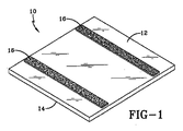
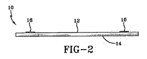
図1及び2について説明すると、変更された太陽電池パネル10が示されている。変更された太陽電池パネル10は底面12と上面14を有する。上面14は、光を受け、光を光起電力セルに透過するように構成されている。底面12は屋根表面に対面するように構成され、フック−ループ型ファスナのパネルファスナ16を含む。本例はほぼ正方形の太陽電池パネルを示すが、他の形状のものを使用することもできる。本例では、パネルファスナ16は太陽電池パネル10に直接固着される。しかし、太陽電池パネル10は支持フレーム又は同種のものを含むものとし、これにパネルファスナ16を固着することができることも認識されたい。
Referring to FIGS. 1 and 2, a modified
パネルファスナ16は突出する複数のフックを有する支持体(例えば薄いシート)の形態のフック型素材とすることができる。逆に、パネルファスナ16は突出する複数のループを有する支持体(例えば薄いシート)の形態のループ型素材とすることもできる。既知のように、フック型素材がループ型素材と接触すると、取り外し可能な機械的結合が形成される。模範的なフック−ループファスナは特許文献1及び特許文献2に見られ、これらの文献は参照することにより本書に援用される。明瞭のために、ファスナなる語を本書を通して使用するが、これについては、対向する相手のファスナが反対型である限り、フック型ファスナ又はループ型ファスナの何れかを使用できることを認識されたい。
The
パネルファスナ16は太陽電池パネル10の底面12に接着剤などで固着することができる。任意の配置を使用できる。例えば、図1及び2に示すように、パネルファスナ16は1対の間隔を置いて配置されたストリップの形にすることができる。他の例では、3つ又はそれより多数の間隔を置いて配置されたストリップを用いることもできる。更に他の例では、パネルファスナ16は底面12の上に格子状又は交差パターンに配置することもできる。更に他の例では、パネルファスナ16は底面12のほぼ全面に設けることもできる。このように、太陽電池パネル10は光を電気に光を変換するために受光する上面14とパネルファスナ16を含む底面12を有する。
The
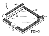
図3及び図4を参照すると、変更された太陽電池パネル10’の代替例が示されている。変更された太陽電池パネル10’は底面12’と上面14’を有する。上面14’は、光を受け、光を光起電力セルに透過するように構成されている。底面12’は屋根表面に対面するように構成される。パネル10’の周辺エッジの周囲にフレーム15が設けられる。フレーム15はパネル10’の補強及び保護のために設けることができる。フック−ループ型ファスナの1つ以上のパネルファスナ16’をフレーム15の底面に固着することができる。本例では、フレーム15の4つの脚のすべてがそれらの上にパネルファスナ16’を有する。他の例では、もっと少数の脚にパネルファスナ16’を設けることができる。例えば、対向する1対の脚にパネルファスナ16’を設けることができる。本例はパネル10’はほぼ正方形であるが、三角形又は他の任意の形状にすることもできる。以上の記載においてパネル10が参照されるが、パネル10’はパネル10の等価な代替パネルとし得ることが認識されよう。
Referring to FIGS. 3 and 4, an alternative example of a modified solar panel 10 'is shown. The modified solar cell panel 10 'has a bottom surface 12' and a top surface 14 '. The top surface 14 'is configured to receive light and transmit the light to the photovoltaic cell. The bottom surface 12 'is configured to face the roof surface. A
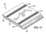
図5及び図6を参照すると、本発明に従って製造された模範的なバラストペイバの全体が20で示されている。複数のバラストペイバを膜ルーフィングシステムとともに使用することにより、主として強風状態中に膜が持ち上がるのを防ぐとともに、2つ以上の隣接する膜シートが互いにつき合わされたとき形成される継ぎ目を完全に維持することができる。更に、ペイバ20は下側の膜を刺し傷やその他の損傷から保護する。ペイバ20はコンクリートやセメントなどで構成することができる。ペイバ20は一般に上面24及び対向底面26を含む本体22を有する薄型の矩形ブロックと記述できる。本体22の一側から突出する上舌部28を設けることができる。本体22の反対側から突出する下舌部30を設けることができる。上舌部28と下舌部30は、ペイバ20を当接関係で配置するとき互いに重なるように構成することができる。この重複又は相互連結構成は強風状態におけるペイバの持ち上がりの防止に役立つ。しかし、種々のペイバ構成が使用可能であることを認識されたい。例えば、ペイバ20は任意の形状にでき、重複機能部を含んでもよく含まなくてもよい。
Referring to FIGS. 5 and 6, an entire exemplary ballast payer manufactured in accordance with the present invention is shown at 20. Use multiple ballast pavers with membrane roofing systems to prevent the membrane from lifting primarily during strong wind conditions and to maintain a complete seam when two or more adjacent membrane sheets are brought together Can do. In addition, the
ペイバファスナ32をペイバ20の上面24の上に設けることができ、接着剤などで固着することができる。ペイバファスナ32は突出する複数のフックを有する薄いシートの形態のフック型素材とすることができる。逆に、ペイバファスナ32は突出する複数のループを有する薄いシートの形態のループ型素材とすることができる。上述したように、対向する相手のファスナが反対型であるかぎり、フック型ファスナ又はループ型ファスナの何れかを使用することができる。従って、パネルファスナ16がループ型ファスナである場合には、相手のペイバファスナ32はフック型ファスナであり、逆の場合も同じである。
A
ペイバファスナ32はペイバ20の上に様々な配列で位置させることがきる。例えば、この例で示すように、ペイバファスナ32は間隔を置いて配置された1対の平行なトリップの形にすることができる。他の例では、間隔を置いて配置された3つ以上のストリップを使用することができる。更に他の例では、ペイバファスナ32は上面24の上に格子状又は交差パターンに配置することができる。更に他の例では、ペイバファスナ32は上面24のほぼ全面に設けることができる。
The
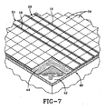
図7を参照すると、ルーフィングシステム40とともに使用されているペイバ20が示されている。ルーフィングシステム40は膜44で覆われた屋根構体42を含むが、ペイバ20はアスファルトベース又は他のビルトアップルーフシステムとともに使用できることを認識されたい。所定の例では、熱貫流を防止するために断熱ボード(図示せず)を屋根構体42と膜44との間に設けることができる。膜44はシートの形にすることができ、例えばアスファルト(bitumus)材料、EPDM、TPOなどからなるものとすることができる。シートは互いにつなぎ合わせることができ、膜44を屋根構体42に取り付ける他の構造的特徴を含むことができる。ペイバ20は膜44の上に当接(隣接)配置することができ、一般に格子状に配置される。ペイバ20は膜44のほぼ全面に配置することができる。更に、上舌部28を下舌部30と重ね合わせて隣接するペイバ20を連結することができる。
Referring to FIG. 7, the
必ずしも屋根表面の全面に太陽電池パネル10を設ける必要があるわけではないので、ペイバファスナ32はすべてのペイバ20に設ける必要はないことが理解されよう。例えば、図7に示す例では、ペイバファスナ32を含むペイバ20の1対の連続行が示されている。これらのペイバ20の連続行は露出したペイバファスナ32の連続したラインを全体的に形成する。他の配置を使用することもできることが認識されよう。一例では、ペイバファスナ32を有するペイバ20の3つ以上の行を設けることができる。他の例では、ペイバファスナ32を有するペイバ20は方形パターン又は格子パターンにすることができる。更に他の例では、ペイバファスナ32を有するペイバ20で全屋根表面を完全に覆うことができる。いずれにせよ、ペイバファスナ32は屋根の上面に配置され、その後その上に太陽電池パネル10を受けることができる。
It will be appreciated that the
図8を参照すると、太陽電池パネル10は、太陽電池パネル10のパネルファスナ16をペイバ20のペイバファスナ32と接触させることによってペイバ20に固着される。その後は、太陽電池パネル10はペイバ20に、従って屋根システム40に機械的に、しかも取り外し可能に結合されたままになる。この機械的結合は太陽電池パネルを強風や他の外力に対して保持するが、取替えや移動が必要なときに技術者が太陽電池パネル10を取り外すことができる程度に十分に弱いものである。明らかなように、太陽電池パネル10は連続する行に配置することができる。他の例では、太陽電池パネル10は屋根表面上に方形パターン又は格子パターンに配置することができる。更に他の例では、太陽電池パネル10は屋根表面の一部分又はほぼ全面を完全に覆うことができる。太陽電池10は複数のケーブル(図示せず)で相互接続することができる。これらのケーブルは分離可能な接続にしてもよいし、しなくてもよい。これらのケーブルは接続箱又は他の受電局まで延長し、そこで電流を調整し、電池システムに使用可能にし、蓄積することができる。
Referring to FIG. 8, the
図9を参照すると、上述したペイバ/太陽電池パネル配列の模範的な設置方法が示されている。第1の工程50において、膜44を屋根構体42の上に設置する。上述したように、屋根構体42と膜44との間に断熱層を随意に設けることができる。膜44は屋根構体42に機械的留め具、接着剤又は任意の他の既知の方法で固着することができる。一例では、屋根構体42と膜44との間に接着剤を設けないで、膜をペイバの重みで押さえつけることができる。
Referring to FIG. 9, an exemplary installation method for the above-described paver / solar panel arrangement is shown. In the
第2の工程52において、ペイバ20を屋根表面に移動させ、その上に配置する。上述したように、太陽電池パネル10に使用さる区域に設置されないペイバ20はペイバファスナ32を持たないものとすることができる。ペイバ20は、当接関係で配列する際に上舌部28が下舌部30に重なるように配置することができる。更に、ペイバファスナ32を持つペイバは連続的に当接関係で配置してほぼ連続するペイバファスナ32の行又はパターンを形成することができる。
In the
一例では、ペイバファスナ32は、屋根に運ぶ前に、ペイバ20上に予め設置される。この例又は他の例では、ペイバファスナ32はペイバ20の製造プロセス中にペイバ20に取り付けることができる。製造プロセス中にペイバファスナ32をペイバ20に取り付けることによって、設置中に時間を節約することができる。更に、工場の比較的清浄な環境のために、特に接着剤を使用する場合に、一層永久的な取り付けが可能になる。
In one example, the
他の例では、ペイバファスナ32は、ペイバの製造後に、第2の工程においてペイバ20に取り付けることができる。この例又は他の例では、ペイバファスナは、ペイバ20を屋根に運ぶ前に、現場で取り付けることができる。他の例では、ペイバファスナ32は、ペイバ20を屋根表面に設置し配置した後にペイバ20に取り付けることができる。
In another example, the
第3の工程54において、太陽電池パネル10をペイバ20の上に設置する。この設置は、太陽電池パネル10のパネルファスナ16をペイバ20のペイバファスナ32と結合させることによって達成される。このようにして、太陽電池パネル10はフック−ループファスナの機械的結合によって屋根に取り付けられる。
In the
最後に、第4の工程56において、太陽電池パネル10を接続箱又は同種のものに相互接続し、これで電流を受け取り、その電流を中間使用に向けるか、後の使用のために電池機構に送ることができる。
Finally, in a
このように、太陽電池パネル10は屋根表面に素早く容易に設置することができる。太陽電池パネル10をペイバ20に固定することによって、永久結合手段を屋根膜に直接取り付ける必要がなくなるので、膜44は損傷されない。更に、フック−ループファスナの取り外し可能性のために、取り替えや修理が一層簡単になる。更にまた、特にペイバ20を屋根表面に設置する前にペイバファスナ32をペイバ20に固定するとき、時間の節約が得られる。
Thus, the
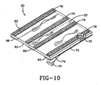
図10−図13を参照すると、別の太陽電池パネル取り付け装置が示されている。図10に示されるように、本発明に従って作られた模範的なルーフパッドの全体が60で示されている。パッド60は一般に柔軟性のシート状にすることができ、ポリマ及び/又はゴム材料からなるものとすることができる。パッド60は上面62及び下面64を有する。下面64は比較的滑らかにすることができるが、上面62は静止摩擦を改善するために織り目加工することができる。接着テープ66を、パッド60の対向エッジ68及び70と中心に一連のストリップとして、下面64に直接接着することができる。接着テープ66は上面72及び下面74を有し、上面72はパッドの下面64に貼り付けられる。
Referring to FIGS. 10-13, another solar panel mounting apparatus is shown. As shown in FIG. 10, an exemplary roof pad made in accordance with the present invention is shown generally at 60. The
一例では、テープ66の貼り付けは工場で製造処理の一部として行うことができる。この段階においては、パッド60は比較的清浄であるため、別個の清浄及び/又は下塗り処理が必要とされない。また、屋外即ち屋根の上では、パッド60が汚されたり汚染されたりするので、パッド60へのテープ66の接着が妨害されるが、これとは対照的に、貼り付けが制御された清浄な状態で行われるために、テープ66とパッド60との間の接着性を最大にすることができる。剥離紙76をテープ66の下面74上に設けることができる。剥離紙76は屋根に設置する前に表面74が塵埃にさらされるのを防ぐ。現場(即ち屋根の上)で設置者に要求されることは剥離紙76を剥がし、粘着パッドを屋根の上に置き、圧力を加えるだけであり、この加圧は単にパッドの上を歩くことにより又はローラを使って行うことができる。
In one example,
他の例では、テープ66の貼り付けは現場で行うことができる。現場で行う場合には、貼り付け前にパッド60の清浄化及び/又は下塗りを行って、汚れや汚染がテープ66とパッド60との間の接合の品質に影響を与えないようにすることができる。現場でのテープ66の貼り付け後は、設置者はパッド60を屋根の上に置き、パッドの上を歩くかトーらを使って圧力を加えるだけでよい。
In another example,
パッド60には、その上面62上に少なくとも1つのパッドファスナ78を設け、このファスナは接着剤などで固着することができる。パッドファスナ78は突出する複数のフックを有する薄いシートの形態のフック型素材とすることができる。逆に、パッドファスナ78は突出する複数のループを有する薄いシートの形態のループ型素材とすることができる。上述したように、対向する相手のファスナが反対型であるかぎり、フック型ファスナ又はループ型ファスナの何れかを使用することができる。従って、パネルファスナ16がループ型ファスナである場合には、相手のパッドファスナ78はフック型ファスナであり、逆の場合も同じである。
The
パッドファスナ78はパッド60の上に様々な配置で置くことができる。例えば、本例で示すように、パッドファスナ78は間隔を置いて配置された4つの平行ストリップの形にすることができる。他の例では、もっと少数もしくは多数の間隔を置いて配置されたストリップを用いることもできる。更に他の例では、パッドファスナ78は上面62上に、格子状又は交差パターンに配置することもできる。更に他の例では、パッドファスナ78は表面62のほぼ全面を覆うこともできる。
The
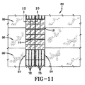
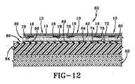
図11及び図12を参照すると、ルーフィングシステム80とともに使用されているパッド60が示されている。ルーフィングシステム80は断熱層84で覆われた屋根構体82を含むことができる。膜86が断熱層84の上に置かれ、固着される。膜86は細長いシートの形にすることができ、例えばアスファルト材料、EPDM、TPOなどからなるものとすることができる。シートは互いにつなぎ合わせることができ、膜86を屋根構体82に取り付けるために必要な他の構造的特徴を含むことができる。パッド86は膜84の上に任意の所望の配列又はパターンに配置することができる。図12に示されるように、接着剤66が膜86に結合してパッド60を所定の位置に保持する。一例では、パッド60は隣接する連続行に配置することができる。他の例では、パッド60は格子状配列に配置することができる。更に他の例では、パッド60は屋根表面のほぼ全面を覆うように配置することができる。
Referring to FIGS. 11 and 12, a
太陽電池パネル10は、太陽電池パネル10のパネルファスナ16をパッド60のパッドファスナ78と接触させることによってパッド60に固着される。その後は、太陽電池パネル10はパッド60、従って屋根システム80に機械的に結合されたままになる。この機械的結合は太陽電池パネルを強風や他の外力に対して保持するが、取替えや移動が必要なときに技術者が太陽電池パネル10を取り外すことができる程度に十分に弱いものである。明らかなように、太陽電池パネル10は連続する行に配置することができる。他の例では、太陽電池パネル10は屋根表面上に方形パターン又は格子パターンに配置することができる。更に他の例では、太陽電池パネル10は屋根表面の一部分又はほぼ全面を完全に覆うことができる。太陽電池10は複数のケーブル(図示せず)で相互接続することができる。これらのケーブルは分離可能な接続にしてもよいし、しなくてもよい。これらのケーブルは接続箱又は他の受電局まで延長し、そこで電流を調整し、電池システムに使用可能にし、蓄積することができる。
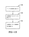
図13を参照すると、上述したパッド/太陽電池パネル配列の模範的な設置方法が示されている。第1の工程90において、予め接着剤が付与されたパッド60を屋根に運び、ここで剥離紙76を除去する。次にパッド60を膜の上に置く。その後、パッドの上を歩くことによって又はローラなどを用いて圧力を加える。1つ以上のパッド60を所望の太陽電池パネル配列に従って配置する。
Referring to FIG. 13, an exemplary installation method for the pad / solar cell panel arrangement described above is shown. In a
第2の工程92において、太陽電池パネル10をパッド60の上に設置する。設置は、太陽電池パネル10のパネルファスナ16をパッド60のパッドファスナ78と接触させることによって達成される。このようにして、太陽電池パネル10はフック−ループファスナの機械的結合によって屋根に固定される。
In the
最後に、第3の工程94において、太陽電池パネル10を接続箱又は同種のものに相互接続し、これで電流を受け取り、その電流を中間使用に向けるか、後の使用のために電池機構に送ることができる。
Finally, in a
上述した例は、太陽電池パネル10を屋根表面に素早く容易に設置することができるため、有利である。パッド60は屋根表面上に任意に容易に配置することができる。更に、太陽電池パネル10は、フック−ループファスナ構成の取り外し可能性のために容易に取り外すことができ、また取り替えることができる。更に、太陽電池パネルはピーク昼光時間中に熱くなり、この熱により下側の屋根膜や他の構造を損傷され得るが、太陽電池パネルと屋根膜との間に設けられるパッド又はペイバは下側の屋根膜を熱損傷から保護する。更にまた、本発明のフック−ループファスナは長期に亘り高い付着強度特性を示す。従って、これらの高い剥離強度のファスナは、屋根に直接取り付けた場合、パネルの除去に大きな力を必要とするために、パネルの除去中に屋根を損傷する可能性がある。本発明のパッド又はペイバはパネルの除去又は取替え中におけるこのような損傷を防止する。最後に、屋根膜は屋根表面上の人の歩行やその他の活動により損傷されやすい。ファスナを、永久的な屋根システムと別の、パッド又はペイバに設けることによって、便利な結合が達成されるのみならず、設置中及び点検中の屋根の保護が達成され、屋根の寿命が長くなる。
The above-described example is advantageous because the
本発明の範囲及び精神から離れることなく種々の変更例及び変形例が当業者に明らかになり、本発明はここに説明した具体例に限定されるものではない。 Various changes and modifications will become apparent to those skilled in the art without departing from the scope and spirit of the invention, and the invention is not limited to the specific examples described herein.
Claims (18)
屋根構体の上に置かれる少なくとも1つのペイバと、
前記ペイバに取り付けられた少なくとも1つのペイバファスナと、
光を受ける上面と、少なくとも1つのデバイスファスナが取り付けられた底面とを有する光起電力デバイスとを備え、
前記少なくとも1つのペイバファスナ及び前記少なくとも1つのデバイスファスナは、いずれか一方がフック構造であれば他方がループ構造であり、互いに接触して前記光起電力デバイスを前記ペイバに固定するように配置されていることを特徴とするエネルギー発生システム。 An energy generation system for installation on a roof structure, the device comprising:
At least one paver placed on the roof structure;
At least one paver fastener attached to the paver;
A photovoltaic device having a top surface for receiving light and a bottom surface to which at least one device fastener is attached;
The at least one paver fastener and the at least one device fastener have a hook structure when one of them is a hook structure, and are arranged to contact each other and fix the photovoltaic device to the paver. An energy generation system characterized by
底面と上面を有し、前記上面にパッドファスナが取り付けられ、前記底面が屋根膜に固定される少なくとも1つのパッドと、
光を受ける上面と、少なくとも1つのデバイスファスナが取り付けられた底面とを有する光起電力デバイスとを備え、
前記少なくとも1つのパッドファスナ及び前記少なくとも1つのデバイスファスナは、いずれか一方がフック構造であれば他方がループ構造であり、互いに接触して前記光起電力デバイスを前記パッドに固定するように配置されていることを特徴とするエネルギー発生システム。 An energy generation system for installation on a roof structure, the device comprising:
At least one pad having a bottom surface and a top surface, wherein a pad fastener is attached to the top surface, and wherein the bottom surface is fixed to a roof membrane;
A photovoltaic device having a top surface for receiving light and a bottom surface to which at least one device fastener is attached;
The at least one pad fastener and the at least one device fastener are arranged so that if one of them is a hook structure, the other is a loop structure and is in contact with each other to fix the photovoltaic device to the pad. An energy generation system characterized by
光を受けるように構成された上面と周辺エッジを有する光起電力デバイスと、
前記光起電力の周辺エッジの少なくとも一部分の周囲に取り付けるように構成され、前記光起電力デバイスの底面と重複する部分を有するフレームと、
前記フレームの重複部分に取り付けられた少なくとも1つのデバイスファスナと、
前記屋根に取り付けられ、前記少なくとも1つのデバイスファスナと結合するように構成された少なくとも1つの屋根ファスナとを備え、
前記少なくとも1つの屋根ファスナ及び前記少なくとも1つのデバイスファスナは、いずれか一方がフック構造であれば他方がループ構造であり、互いに接触して前記光起電力デバイスを前記屋根に固定するように配置されていることを特徴とするエネルギー発生システム。 An energy generation system for installation on a roof structure, the device comprising:
A photovoltaic device having a top surface and a peripheral edge configured to receive light;
A frame configured to be mounted around at least a portion of a peripheral edge of the photovoltaic device and having a portion overlapping a bottom surface of the photovoltaic device;
At least one device fastener attached to an overlapping portion of the frame;
At least one roof fastener attached to the roof and configured to couple with the at least one device fastener;
The at least one roof fastener and the at least one device fastener are arranged so that if one of them is a hook structure, the other is a loop structure and is in contact with each other to fix the photovoltaic device to the roof. An energy generation system characterized by
Applications Claiming Priority (2)
| Application Number | Priority Date | Filing Date | Title |
|---|---|---|---|
| US86056106P | 2006-11-21 | 2006-11-21 | |
| PCT/US2007/024328 WO2008063660A2 (en) | 2006-11-21 | 2007-11-21 | Hook and loop attachment of solar panels to roofing membranes |
Related Child Applications (1)
| Application Number | Title | Priority Date | Filing Date |
|---|---|---|---|
| JP2014157916A Division JP6050791B2 (en) | 2006-11-21 | 2014-08-01 | Hook-loop attachment of solar panel to roof membrane |
Publications (2)
| Publication Number | Publication Date |
|---|---|
| JP2010510419A true JP2010510419A (en) | 2010-04-02 |
| JP2010510419A5 JP2010510419A5 (en) | 2010-12-24 |
Family
ID=39313034
Family Applications (2)
| Application Number | Title | Priority Date | Filing Date |
|---|---|---|---|
| JP2009538412A Pending JP2010510419A (en) | 2006-11-21 | 2007-11-21 | Hook-loop attachment of solar panel to roof membrane |
| JP2014157916A Expired - Fee Related JP6050791B2 (en) | 2006-11-21 | 2014-08-01 | Hook-loop attachment of solar panel to roof membrane |
Family Applications After (1)
| Application Number | Title | Priority Date | Filing Date |
|---|---|---|---|
| JP2014157916A Expired - Fee Related JP6050791B2 (en) | 2006-11-21 | 2014-08-01 | Hook-loop attachment of solar panel to roof membrane |
Country Status (7)
| Country | Link |
|---|---|
| US (2) | US8505249B2 (en) |
| EP (1) | EP2095432A2 (en) |
| JP (2) | JP2010510419A (en) |
| KR (1) | KR20090085112A (en) |
| CN (2) | CN103944495A (en) |
| HK (1) | HK1138107A1 (en) |
| WO (1) | WO2008063660A2 (en) |
Cited By (1)
| Publication number | Priority date | Publication date | Assignee | Title |
|---|---|---|---|---|
| JP2012518283A (en) * | 2009-02-19 | 2012-08-09 | サンゴバン・パフォーマンス・プラスティックス・コーポレーション | Photovoltaic cell mounting system on fluoropolymer structure film |
Families Citing this family (64)
| Publication number | Priority date | Publication date | Assignee | Title |
|---|---|---|---|---|
| KR20090085112A (en) | 2006-11-21 | 2009-08-06 | 파이어스톤 빌딩 프라덕츠 캄파니, 엘엘씨 | Hook and loop attachment of solar panels to roofing membranes |
| EP2063199B1 (en) * | 2007-11-23 | 2012-05-30 | BELECTRIC Trading GmbH | Arrangement consisting of an attachment underlay with photovoltaic modules |
| WO2009089484A2 (en) * | 2008-01-10 | 2009-07-16 | Kalkanoglu Husnu M | Roofing and siding products having receptor zones and photovoltaic roofing and siding elements and systems using them |
| US8316593B2 (en) * | 2009-03-18 | 2012-11-27 | Garland Industries, Inc. | Solar roofing system |
| JP5663143B2 (en) * | 2009-05-07 | 2015-02-04 | 株式会社大林組 | SOLAR CELL MODULE AND METHOD OF MOUNTING SOLAR CELL MODULE |
| JP2010263089A (en) * | 2009-05-07 | 2010-11-18 | Ohbayashi Corp | Solar battery unit and method for attaching the solar battery unit |
| US8915030B2 (en) * | 2009-10-22 | 2014-12-23 | Dow Global Technologies Llc | Direct mounted photovoltaic device with improved adhesion and method thereof |
| NL2006964C2 (en) * | 2011-06-17 | 2012-12-18 | Johnsol B V | DEVICE FOR FIXING SOLAR PANELS. |
| CN102400982A (en) * | 2011-06-30 | 2012-04-04 | 浙江正泰太阳能科技有限公司 | Device and method for installing film assembly by using pressure block and adhesive tape |
| US9537033B2 (en) | 2011-07-29 | 2017-01-03 | Dow Global Technologies Llc | Interface system and method for photovoltaic cladding to standard cladding |
| DE102012000196A1 (en) * | 2012-01-09 | 2013-07-11 | Gottlieb Binder Gmbh & Co. Kg | Method for producing a fastening system, in particular for components of photovoltaic systems |
| US9121779B2 (en) * | 2012-01-27 | 2015-09-01 | Hail Signature Technologies, L.L.C. | System for recording information associated with hail storm event and determining structure damage based on same |
| CN102808484A (en) * | 2012-07-27 | 2012-12-05 | 保定天威薄膜光伏有限公司 | Photovoltaic roof and installation method thereof |
| US10727779B2 (en) * | 2012-10-01 | 2020-07-28 | Building Materials Investment Corporation | Solar panel roof system with raised access panels |
| US11894796B2 (en) | 2012-10-02 | 2024-02-06 | Bmic Llc | Roof integrated solar power system with top mounted electrical components and cables |
| KR101256648B1 (en) | 2013-01-10 | 2013-04-23 | 영남대학교 산학협력단 | Panel equipped with solar cell module and outer of building thereof |
| US9551509B2 (en) * | 2014-01-16 | 2017-01-24 | Jonathan Port | Apparatuses and methods for fastening roofing strapsand structural members to roofs |
| US9540821B2 (en) | 2014-02-14 | 2017-01-10 | Johns Manville | Roofing membranes having multiple adhesive regions and method therefor |
| US9234352B2 (en) * | 2014-02-14 | 2016-01-12 | Johns Manville | Roofing membranes having multiple adhesive regions and method therefor |
| CN105587080A (en) * | 2014-11-11 | 2016-05-18 | 薛连丰 | Waterproof roof assembling structure integrated with solar panel |
| US9212488B1 (en) * | 2014-12-01 | 2015-12-15 | Johns Manville | Sheet roofing with pre-taped seams and tape therefor |
| US20170037629A1 (en) * | 2015-08-05 | 2017-02-09 | Milliken & Company | Magnetically attached building composite |
| US10513853B2 (en) * | 2016-03-24 | 2019-12-24 | Owens Corning Intellectual Capital, Llc | Roof covering and method of applying the same |
| US10589491B2 (en) * | 2016-04-16 | 2020-03-17 | Module Design, Inc. | Removable and re-attachable roof system for modular residential construction |
| WO2018069333A1 (en) * | 2016-10-11 | 2018-04-19 | Designergy Sa | Photovoltaic element and mounted surface comprising such photovoltaic elements |
| US10784816B2 (en) * | 2018-12-20 | 2020-09-22 | Hall Labs Llc | Electrical and mechanical roof underlayment |
| US11578494B2 (en) | 2017-06-05 | 2023-02-14 | Millennium Slate, Llc | Roofing system and method |
| US10829937B2 (en) * | 2017-06-05 | 2020-11-10 | Millennium Slate, Llc | Roofing system and method |
| US11927017B2 (en) * | 2017-06-05 | 2024-03-12 | Millennuim Slate, LLC | Roofing system and method |
| US11549639B2 (en) | 2018-09-25 | 2023-01-10 | Green Link Holdings, LLC | Magnetic roofing apparatus |
| GB201905849D0 (en) | 2019-04-26 | 2019-06-12 | Roof Tiles Tech Limited | Photovoltaic roof covering and method of manufacture |
| CA3159500A1 (en) * | 2019-11-27 | 2021-06-03 | William Sirski | Roof integrated photovoltaic module with spacer |
| US11398795B2 (en) * | 2019-12-20 | 2022-07-26 | GAF Energy LLC | Roof integrated photovoltaic system |
| MX2022009069A (en) | 2020-01-22 | 2023-01-05 | GAF Energy LLC | Integrated photovoltaic roofing shingles, methods, systems, and kits thereof. |
| KR102135829B1 (en) | 2020-02-10 | 2020-07-21 | 주식회사 태신이앤씨 | Solar panels installing device for roof of cattle shed |
| WO2021168126A1 (en) | 2020-02-18 | 2021-08-26 | GAF Energy LLC | Photovoltaic module with textured superstrate providing shingle-mimicking appearance |
| MX2022010603A (en) | 2020-02-27 | 2022-11-14 | GAF Energy LLC | Photovoltaic module with light-scattering encapsulant providing shingle-mimicking appearance. |
| US11961928B2 (en) | 2020-02-27 | 2024-04-16 | GAF Energy LLC | Photovoltaic module with light-scattering encapsulant providing shingle-mimicking appearance |
| CA3174671A1 (en) | 2020-04-09 | 2021-10-14 | GAF Energy LLC | Three-dimensional laminate photovoltaic module |
| CN111478656B (en) * | 2020-04-17 | 2021-05-14 | 绍兴市慧融臻合新能源科技有限公司 | Solar power generation equipment |
| CN115812034A (en) | 2020-04-30 | 2023-03-17 | Gaf能源有限责任公司 | Photovoltaic module front and back sheets |
| CN115461950A (en) | 2020-05-13 | 2022-12-09 | Gaf能源有限责任公司 | Power cable penetration piece |
| US11251744B1 (en) | 2020-06-04 | 2022-02-15 | GAF Energy LLC | Photovoltaic shingles and methods of installing same |
| USD950189S1 (en) | 2020-07-08 | 2022-05-03 | Spectrum Brands, Inc. | Spiral pet treat |
| US11843067B2 (en) | 2020-07-22 | 2023-12-12 | GAF Energy LLC | Photovoltaic modules |
| MX2023001822A (en) | 2020-08-11 | 2023-05-08 | GAF Energy LLC | Roof mounted photovoltaic system and method for wireless transfer of electrical energy. |
| WO2022051593A1 (en) | 2020-09-03 | 2022-03-10 | GAF Energy LLC | Building integrated photovoltaic system |
| USD950481S1 (en) | 2020-10-02 | 2022-05-03 | GAF Energy LLC | Solar roofing system |
| USD950482S1 (en) | 2020-10-02 | 2022-05-03 | GAF Energy LLC | Solar roofing system |
| US11545928B2 (en) | 2020-10-13 | 2023-01-03 | GAF Energy LLC | Solar roofing system |
| US11444569B2 (en) | 2020-10-14 | 2022-09-13 | GAF Energy LLC | Mounting apparatus for photovoltaic modules |
| WO2022094049A1 (en) | 2020-10-29 | 2022-05-05 | GAF Energy LLC | System of roofing and photovoltaic shingles and methods of installing same |
| US11486144B2 (en) | 2020-11-12 | 2022-11-01 | GAF Energy LLC | Roofing shingles with handles |
| CA3197598A1 (en) | 2020-11-13 | 2022-05-19 | Gabriela Bunea | Photovoltaic module systems and methods |
| US11459757B2 (en) | 2021-01-19 | 2022-10-04 | GAF Energy LLC | Watershedding features for roofing shingles |
| WO2022178311A1 (en) | 2021-02-19 | 2022-08-25 | GAF Energy LLC | Photovoltaic module for a roof with continuous fiber tape |
| US11527665B2 (en) | 2021-05-06 | 2022-12-13 | GAF Energy LLC | Photovoltaic module with transparent perimeter edges |
| CA3215217A1 (en) | 2021-06-02 | 2022-12-08 | Richard Perkins | Photovoltaic module with light-scattering encapsulant providing shingle-mimicking appearance |
| WO2023287584A1 (en) | 2021-07-16 | 2023-01-19 | GAF Energy LLC | Roof material storage bracket |
| US11728759B2 (en) | 2021-09-01 | 2023-08-15 | GAF Energy LLC | Photovoltaic modules for commercial roofing |
| US11824486B2 (en) | 2022-01-20 | 2023-11-21 | GAF Energy LLC | Roofing shingles for mimicking the appearance of photovoltaic modules |
| US11984521B2 (en) | 2022-03-10 | 2024-05-14 | GAF Energy LLC | Combined encapsulant and backsheet for photovoltaic modules |
| US11781310B1 (en) | 2022-04-27 | 2023-10-10 | Modology Design Group | Modular home delivery system |
| US11811361B1 (en) | 2022-12-14 | 2023-11-07 | GAF Energy LLC | Rapid shutdown device for photovoltaic modules |
Citations (8)
| Publication number | Priority date | Publication date | Assignee | Title |
|---|---|---|---|---|
| JPS5753659U (en) * | 1980-09-11 | 1982-03-29 | ||
| US5316592A (en) * | 1992-08-31 | 1994-05-31 | Dinwoodie Thomas L | Solar cell roofing assembly |
| JPH0722640A (en) * | 1993-07-05 | 1995-01-24 | Fuji Electric Co Ltd | Solar battery module |
| JPH0983000A (en) * | 1995-09-11 | 1997-03-28 | Kajima Corp | Solar cell module for mounting large-sized glass surface |
| JPH10231600A (en) * | 1997-02-18 | 1998-09-02 | Daiwa House Ind Co Ltd | Solar battery fitting structure to building |
| JP2000269535A (en) * | 1999-01-14 | 2000-09-29 | Canon Inc | Solar battery module and power generating device and method for separating the solar battery module and method for reproducing the module |
| JP2002256665A (en) * | 2001-03-02 | 2002-09-11 | Sekisui Chem Co Ltd | Roof member attached with solar cell and roofing construction |
| JP2004360352A (en) * | 2003-06-06 | 2004-12-24 | Taisei Corp | Solar battery module for tiled roof and its installation method |
Family Cites Families (81)
| Publication number | Priority date | Publication date | Assignee | Title |
|---|---|---|---|---|
| US3071180A (en) * | 1953-11-23 | 1963-01-01 | Johns Manville Fiber Glass Inc | Apparatus for continuously producing reinforced plastic structural panels |
| US3077703A (en) * | 1959-04-17 | 1963-02-19 | Wood Conversion Co | Roof deck structure |
| US3288136A (en) | 1964-01-07 | 1966-11-29 | Douglas W Lund | Tube lock |
| US3459597A (en) * | 1966-02-04 | 1969-08-05 | Trw Inc | Solar cells with flexible overlapping bifurcated connector |
| US3370818A (en) | 1966-06-28 | 1968-02-27 | Herbert M. Perr | Fabric type fastening means |
| US3403429A (en) | 1966-11-09 | 1968-10-01 | Smith George Walter Henry | Strip fastening means |
| US3488905A (en) * | 1967-12-29 | 1970-01-13 | William C Campbell | Building roof structure |
| US3769091A (en) * | 1972-03-31 | 1973-10-30 | Us Navy | Shingled array of solar cells |
| US3753458A (en) * | 1972-04-12 | 1973-08-21 | A Lazarek | Demountable car window screen and fastening means therefor |
| US3817015A (en) * | 1972-10-24 | 1974-06-18 | J Frangos | Convertible floor system |
| US4020989A (en) * | 1975-10-20 | 1977-05-03 | H. H. Robertson Company | Light transmitting building panel |
| US3992121A (en) * | 1976-01-19 | 1976-11-16 | Felt Products Mfg. Co. | Deck and roadway gap sealing assembly |
| FR2350695A1 (en) * | 1976-05-03 | 1977-12-02 | Aerospatiale | SOLAR ELECTRIC ENERGY GENERATOR |
| US4274239A (en) * | 1976-09-03 | 1981-06-23 | Carroll Research, Inc. | Building structure |
| US4068428A (en) * | 1976-10-22 | 1978-01-17 | Peterson Iii O James | Insulation window |
| US4283451A (en) * | 1978-06-09 | 1981-08-11 | Ziklag Reinforced Plastics, Ltd. | Light-transmitting roofing and cladding panel |
| US4249589A (en) * | 1979-08-30 | 1981-02-10 | Loeb Nackey S | Apparatus for mounting an environment controlling sheet |
| US4616456A (en) * | 1983-04-25 | 1986-10-14 | Parker Gregory H | Insulated window cover apparatus |
| US4601150A (en) * | 1985-02-04 | 1986-07-22 | The Dow Chemical Company | Roofing element and roof employing such element |
| US4636579A (en) | 1985-03-18 | 1987-01-13 | Energy Conversion Devices, Inc. | Retractable power supply |
| US4677248A (en) * | 1985-09-13 | 1987-06-30 | Lacey Thomas G | Apparatus for mounting solar cells |
| US4702046A (en) * | 1985-11-08 | 1987-10-27 | General Communications, Inc. | Acoustical wall panel |
| US4674244A (en) * | 1986-07-17 | 1987-06-23 | Single-Ply Institute Of America, Inc. | Roof construction having insulation structure, membrane and photovoltaic cells |
| US4744189A (en) * | 1986-08-14 | 1988-05-17 | Snap-Wall, Inc. | Removable wall panel |
| US4886554A (en) | 1988-09-29 | 1989-12-12 | Gaf Corporation | Solar roofing assembly |
| US4974384A (en) * | 1988-11-07 | 1990-12-04 | Tac-Fast System Sa | Structural assembly system |
| US4977730A (en) * | 1989-09-06 | 1990-12-18 | National Concrete Masonry Association | Roof paver element and system |
| US5215598A (en) * | 1989-09-06 | 1993-06-01 | Sanyo Electric Co., Ltd. | Flexible photovoltaic device and manufacturing method thereof |
| US5377468A (en) * | 1993-04-27 | 1995-01-03 | Hanover Architectural Products, Inc. | Aerodynamically stable roof paver system and ballast block therefor |
| US5437735A (en) * | 1993-12-30 | 1995-08-01 | United Solar Systems Corporation | Photovoltaic shingle system |
| US5575861A (en) * | 1993-12-30 | 1996-11-19 | United Solar Systems Corporation | Photovoltaic shingle system |
| US5474620A (en) * | 1994-05-16 | 1995-12-12 | United Solar Systems Corporation | Cut resistant laminate for the light incident surface of a photovoltaic module |
| US5505788A (en) * | 1994-06-29 | 1996-04-09 | Dinwoodie; Thomas L. | Thermally regulated photovoltaic roofing assembly |
| US5522943A (en) | 1994-12-05 | 1996-06-04 | Spencer; Jerald C. | Portable power supply |
| US5928437A (en) * | 1995-02-09 | 1999-07-27 | The Boeing Company | Microarray for efficient energy generation for satellites |
| US5590495A (en) * | 1995-07-06 | 1997-01-07 | Bressler Group Inc. | Solar roofing system |
| US5746839A (en) * | 1996-04-08 | 1998-05-05 | Powerlight Corporation | Lightweight, self-ballasting photovoltaic roofing assembly |
| US7185473B2 (en) * | 1996-07-19 | 2007-03-06 | Tac-Fast Georgia, L.L.C. | Anchor sheet and anchor sheet module |
| JP3825843B2 (en) * | 1996-09-12 | 2006-09-27 | キヤノン株式会社 | Solar cell module |
| DE29619119U1 (en) | 1996-09-23 | 1998-01-22 | Atlantis Solar Systeme Ag | Photovoltaic solar roof |
| JP2864117B2 (en) | 1997-02-07 | 1999-03-03 | 鹿島建設株式会社 | Power supply |
| EP1009893A1 (en) * | 1997-02-18 | 2000-06-21 | Minnesota Mining And Manufacturing Company | Method and apparatus for roof covering |
| US6061978A (en) * | 1997-06-25 | 2000-05-16 | Powerlight Corporation | Vented cavity radiant barrier assembly and method |
| JPH11172895A (en) * | 1997-12-08 | 1999-06-29 | Matsuya Shokai:Kk | Floor-covering material execution method and floor-covering material thereof |
| JP3188234B2 (en) * | 1997-12-18 | 2001-07-16 | 洋之輔 伊藤 | Wall fixing structure for plate members |
| DE29817398U1 (en) * | 1998-09-29 | 1999-02-11 | Wendker Gmbh & Co Kg | Velcro fastening system for wall elements |
| US6032291A (en) | 1998-12-29 | 2000-03-07 | Asenguah; Augustus | Solar powered head cooling device |
| DE19921265C2 (en) | 1999-05-07 | 2001-05-23 | Webasto Vehicle Sys Int Gmbh | Solar module for mounting on vehicles, method of manufacturing the same and its use |
| EP1071137A3 (en) * | 1999-07-21 | 2007-03-21 | Kaneka Corporation | Roofing tile having photovoltaic module to generate power |
| JP2001148500A (en) * | 1999-11-22 | 2001-05-29 | Sanyo Electric Co Ltd | Solar cell module |
| US6729081B2 (en) * | 2000-06-09 | 2004-05-04 | United Solar Systems Corporation | Self-adhesive photovoltaic module |
| US6615555B2 (en) * | 2000-06-30 | 2003-09-09 | Michael Madden | Light transmitting storm shutter system |
| FR2813927B1 (en) * | 2000-09-11 | 2003-09-26 | Solvay | MULTI-LAYER PLASTIC INSULATING PANEL |
| US6278062B1 (en) * | 2001-01-08 | 2001-08-21 | Robert C. Sowdon | Article of manufacture for a cover plate and a faceplate without frontal screws for flush mounted electrical outlet boxes installed with switches or outlet receptacles |
| US6570084B2 (en) * | 2001-07-10 | 2003-05-27 | Powerlight Corporation | Pressure equalizing photovoltaic assembly and method |
| US6501013B1 (en) * | 2001-07-10 | 2002-12-31 | Powerlight Corporation | Photovoltaic assembly array with covered bases |
| US6875914B2 (en) * | 2002-01-14 | 2005-04-05 | United Solar Systems Corporation | Photovoltaic roofing structure |
| US6883290B2 (en) * | 2002-02-20 | 2005-04-26 | Powerlight Corporation | Shingle system and method |
| US20030154667A1 (en) * | 2002-02-20 | 2003-08-21 | Dinwoodie Thomas L. | Shingle system |
| JP2004036098A (en) * | 2002-06-28 | 2004-02-05 | Ebara Corp | Lightweight solar cell mounting structure |
| JP2004092212A (en) * | 2002-08-30 | 2004-03-25 | Daiken Trade & Ind Co Ltd | Flooring material and its execution method |
| JP4315665B2 (en) * | 2002-10-30 | 2009-08-19 | シャープ株式会社 | End face sealing member of solar cell module and solar cell module using the same |
| US6956500B1 (en) * | 2002-11-29 | 2005-10-18 | M & M Systems, Inc. | Real-time residential energy monitor |
| US6662572B1 (en) * | 2002-12-30 | 2003-12-16 | The United States Of America As Represented By The Administrator Of The National Aeronautics And Space Administration | Solar powered automobile interior climate control system |
| WO2004109034A1 (en) * | 2003-06-02 | 2004-12-16 | Avery Dennison Corporation | Cool roof covering |
| DE10329184A1 (en) * | 2003-06-27 | 2005-01-20 | SESOL Gesellschaft für solare Systeme mbH | System for fastening of roof construction elements has components to be connected provided at connecting points to corresponding parts of adhesion connector acting under compression |
| US6959993B2 (en) | 2003-07-10 | 2005-11-01 | Energy Innovations, Inc. | Solar concentrator array with individually adjustable elements |
| US7587864B2 (en) * | 2003-11-19 | 2009-09-15 | Elk Premium Building Products, Inc. | Photovoltaic building materials and related methods of installation |
| US7406800B2 (en) * | 2004-05-18 | 2008-08-05 | Andalay Solar, Inc. | Mounting system for a solar panel |
| US7219476B2 (en) * | 2004-11-30 | 2007-05-22 | Akins Faron L | Roofing system |
| JP2006170568A (en) * | 2004-12-17 | 2006-06-29 | Mitsubishi Kagaku Sanshi Corp | Heating system |
| US7064280B1 (en) * | 2005-09-20 | 2006-06-20 | Rodgers Jimmie A | Radiation shielding panel construction system and panels therefore |
| US20090266400A1 (en) * | 2006-04-22 | 2009-10-29 | Deliddo Jack P | Apparatus and method for attaching solar panels to roof system surfaces |
| US20080245404A1 (en) * | 2007-04-05 | 2008-10-09 | Deliddo Jack P | Apparatus and method for attaching solar panels to roof system surfaces |
| US20070295390A1 (en) * | 2006-05-05 | 2007-12-27 | Nanosolar, Inc. | Individually encapsulated solar cells and solar cell strings having a substantially inorganic protective layer |
| US20070266660A1 (en) * | 2006-05-19 | 2007-11-22 | Solar Century Holdings Liimited | Apparatus for covering a roof |
| GB0610525D0 (en) | 2006-05-26 | 2006-07-05 | Solar Century Holdings Ltd | Flexible solar collector roof system |
| US20070272320A1 (en) * | 2006-05-24 | 2007-11-29 | James Roberson | Reusable duct wrap |
| WO2008051997A2 (en) * | 2006-10-23 | 2008-05-02 | Ascent Solar Technologies, Inc. | Flexible photovoltaic array with integrated wiring and control circuitry, and associated methods |
| US8003882B2 (en) * | 2006-11-07 | 2011-08-23 | General Electric Company | Methods and systems for asphalt roof integrated photovoltaic modules |
| KR20090085112A (en) | 2006-11-21 | 2009-08-06 | 파이어스톤 빌딩 프라덕츠 캄파니, 엘엘씨 | Hook and loop attachment of solar panels to roofing membranes |
-
2007
- 2007-11-21 KR KR1020097012619A patent/KR20090085112A/en not_active Application Discontinuation
- 2007-11-21 EP EP07862196A patent/EP2095432A2/en not_active Withdrawn
- 2007-11-21 CN CN201410105476.1A patent/CN103944495A/en active Pending
- 2007-11-21 WO PCT/US2007/024328 patent/WO2008063660A2/en active Application Filing
- 2007-11-21 JP JP2009538412A patent/JP2010510419A/en active Pending
- 2007-11-21 US US12/515,822 patent/US8505249B2/en not_active Expired - Fee Related
- 2007-11-21 CN CN200780049802.XA patent/CN101584049B/en not_active Expired - Fee Related
-
2010
- 2010-05-17 HK HK10104827.9A patent/HK1138107A1/en not_active IP Right Cessation
-
2013
- 2013-08-09 US US13/963,396 patent/US20130318895A1/en not_active Abandoned
-
2014
- 2014-08-01 JP JP2014157916A patent/JP6050791B2/en not_active Expired - Fee Related
Patent Citations (8)
| Publication number | Priority date | Publication date | Assignee | Title |
|---|---|---|---|---|
| JPS5753659U (en) * | 1980-09-11 | 1982-03-29 | ||
| US5316592A (en) * | 1992-08-31 | 1994-05-31 | Dinwoodie Thomas L | Solar cell roofing assembly |
| JPH0722640A (en) * | 1993-07-05 | 1995-01-24 | Fuji Electric Co Ltd | Solar battery module |
| JPH0983000A (en) * | 1995-09-11 | 1997-03-28 | Kajima Corp | Solar cell module for mounting large-sized glass surface |
| JPH10231600A (en) * | 1997-02-18 | 1998-09-02 | Daiwa House Ind Co Ltd | Solar battery fitting structure to building |
| JP2000269535A (en) * | 1999-01-14 | 2000-09-29 | Canon Inc | Solar battery module and power generating device and method for separating the solar battery module and method for reproducing the module |
| JP2002256665A (en) * | 2001-03-02 | 2002-09-11 | Sekisui Chem Co Ltd | Roof member attached with solar cell and roofing construction |
| JP2004360352A (en) * | 2003-06-06 | 2004-12-24 | Taisei Corp | Solar battery module for tiled roof and its installation method |
Cited By (1)
| Publication number | Priority date | Publication date | Assignee | Title |
|---|---|---|---|---|
| JP2012518283A (en) * | 2009-02-19 | 2012-08-09 | サンゴバン・パフォーマンス・プラスティックス・コーポレーション | Photovoltaic cell mounting system on fluoropolymer structure film |
Also Published As
| Publication number | Publication date |
|---|---|
| WO2008063660B1 (en) | 2008-10-16 |
| CN101584049A (en) | 2009-11-18 |
| CN101584049B (en) | 2014-08-13 |
| US20100059104A1 (en) | 2010-03-11 |
| US20130318895A1 (en) | 2013-12-05 |
| HK1138107A1 (en) | 2010-08-13 |
| CN103944495A (en) | 2014-07-23 |
| WO2008063660A3 (en) | 2008-07-03 |
| WO2008063660A2 (en) | 2008-05-29 |
| US8505249B2 (en) | 2013-08-13 |
| KR20090085112A (en) | 2009-08-06 |
| JP6050791B2 (en) | 2016-12-21 |
| JP2015007369A (en) | 2015-01-15 |
| EP2095432A2 (en) | 2009-09-02 |
Similar Documents
| Publication | Publication Date | Title |
|---|---|---|
| JP6050791B2 (en) | Hook-loop attachment of solar panel to roof membrane | |
| US20080245405A1 (en) | Integrated Solar Cell Roofing System and Method of Manufacture | |
| US10563406B2 (en) | Roofing products having receptor zones and photovoltaic roofing elements and systems using them | |
| US20220368279A1 (en) | Systems and methods for applying flexible solar panels to flexible underlying membranes | |
| US8863451B2 (en) | Photovoltaic roofing systems and methods for repairing them | |
| US8314324B2 (en) | Laminated thin film photovoltaic systems | |
| US20110017278A1 (en) | Roofing products, photovoltaic roofing elements and systems using them | |
| US20110030761A1 (en) | Roofing products, photovoltaic roofing elements and systems using them | |
| US20120198780A1 (en) | Method for attaching a solar module to a substrate using an adhesive | |
| WO2006043658A1 (en) | Solar battery module device and method of installing the same | |
| JP5772323B2 (en) | Waterproof layer maintenance method | |
| JP2007180314A (en) | Solar battery module | |
| US20190296683A1 (en) | Adhesive mounting of photovoltaic modules on roofs | |
| JP4738669B2 (en) | Solar cell roofing material | |
| JP3708034B2 (en) | Roof structure with solar cell and construction method thereof | |
| KR102453691B1 (en) | Rooftop waterproofing method of installing solar modules | |
| CN218103010U (en) | Photovoltaic power generation device and building | |
| JP3119817B2 (en) | Solar cell panel mounting structure and solar cell panel mounting method | |
| JP2002368245A (en) | Structure with solar battery module and method of installing the same | |
| JPH11350686A (en) | Roof structure having power generating function | |
| JP2004052508A (en) | Functional member mounting apparatus and functional member mounting structure using it | |
| JP2007035976A (en) | Self-standing power generation system by solar cell |
Legal Events
| Date | Code | Title | Description |
|---|---|---|---|
| A521 | Written amendment |
Free format text: JAPANESE INTERMEDIATE CODE: A523 Effective date: 20101102 |
|
| A621 | Written request for application examination |
Free format text: JAPANESE INTERMEDIATE CODE: A621 Effective date: 20101102 |
|
| A131 | Notification of reasons for refusal |
Free format text: JAPANESE INTERMEDIATE CODE: A131 Effective date: 20120612 |
|
| A521 | Written amendment |
Free format text: JAPANESE INTERMEDIATE CODE: A523 Effective date: 20120912 |
|
| A131 | Notification of reasons for refusal |
Free format text: JAPANESE INTERMEDIATE CODE: A131 Effective date: 20130514 |
|
| A521 | Written amendment |
Free format text: JAPANESE INTERMEDIATE CODE: A523 Effective date: 20130809 |
|
| A02 | Decision of refusal |
Free format text: JAPANESE INTERMEDIATE CODE: A02 Effective date: 20140401 |