JP2010503113A - Integrated pressure-sensitive lens assembly - Google Patents
Integrated pressure-sensitive lens assembly Download PDFInfo
- Publication number
- JP2010503113A JP2010503113A JP2009527441A JP2009527441A JP2010503113A JP 2010503113 A JP2010503113 A JP 2010503113A JP 2009527441 A JP2009527441 A JP 2009527441A JP 2009527441 A JP2009527441 A JP 2009527441A JP 2010503113 A JP2010503113 A JP 2010503113A
- Authority
- JP
- Japan
- Prior art keywords
- electronic device
- touch screen
- lens
- screen assembly
- pressure
- Prior art date
- Legal status (The legal status is an assumption and is not a legal conclusion. Google has not performed a legal analysis and makes no representation as to the accuracy of the status listed.)
- Pending
Links
Images


Classifications
-
- G—PHYSICS
- G06—COMPUTING; CALCULATING OR COUNTING
- G06F—ELECTRIC DIGITAL DATA PROCESSING
- G06F1/00—Details not covered by groups G06F3/00 - G06F13/00 and G06F21/00
- G06F1/16—Constructional details or arrangements
- G06F1/1613—Constructional details or arrangements for portable computers
- G06F1/1626—Constructional details or arrangements for portable computers with a single-body enclosure integrating a flat display, e.g. Personal Digital Assistants [PDAs]
-
- G—PHYSICS
- G06—COMPUTING; CALCULATING OR COUNTING
- G06F—ELECTRIC DIGITAL DATA PROCESSING
- G06F3/00—Input arrangements for transferring data to be processed into a form capable of being handled by the computer; Output arrangements for transferring data from processing unit to output unit, e.g. interface arrangements
- G06F3/01—Input arrangements or combined input and output arrangements for interaction between user and computer
- G06F3/03—Arrangements for converting the position or the displacement of a member into a coded form
- G06F3/041—Digitisers, e.g. for touch screens or touch pads, characterised by the transducing means
- G06F3/0414—Digitisers, e.g. for touch screens or touch pads, characterised by the transducing means using force sensing means to determine a position
- G06F3/04142—Digitisers, e.g. for touch screens or touch pads, characterised by the transducing means using force sensing means to determine a position the force sensing means being located peripherally, e.g. disposed at the corners or at the side of a touch sensing plate
-
- G—PHYSICS
- G06—COMPUTING; CALCULATING OR COUNTING
- G06F—ELECTRIC DIGITAL DATA PROCESSING
- G06F1/00—Details not covered by groups G06F3/00 - G06F13/00 and G06F21/00
- G06F1/16—Constructional details or arrangements
- G06F1/1613—Constructional details or arrangements for portable computers
- G06F1/1633—Constructional details or arrangements of portable computers not specific to the type of enclosures covered by groups G06F1/1615 - G06F1/1626
- G06F1/1637—Details related to the display arrangement, including those related to the mounting of the display in the housing
- G06F1/1643—Details related to the display arrangement, including those related to the mounting of the display in the housing the display being associated to a digitizer, e.g. laptops that can be used as penpads
-
- G—PHYSICS
- G06—COMPUTING; CALCULATING OR COUNTING
- G06F—ELECTRIC DIGITAL DATA PROCESSING
- G06F1/00—Details not covered by groups G06F3/00 - G06F13/00 and G06F21/00
- G06F1/16—Constructional details or arrangements
- G06F1/1613—Constructional details or arrangements for portable computers
- G06F1/1633—Constructional details or arrangements of portable computers not specific to the type of enclosures covered by groups G06F1/1615 - G06F1/1626
- G06F1/1656—Details related to functional adaptations of the enclosure, e.g. to provide protection against EMI, shock, water, or to host detachable peripherals like a mouse or removable expansions units like PCMCIA cards, or to provide access to internal components for maintenance or to removable storage supports like CDs or DVDs, or to mechanically mount accessories
- G06F1/1658—Details related to functional adaptations of the enclosure, e.g. to provide protection against EMI, shock, water, or to host detachable peripherals like a mouse or removable expansions units like PCMCIA cards, or to provide access to internal components for maintenance or to removable storage supports like CDs or DVDs, or to mechanically mount accessories related to the mounting of internal components, e.g. disc drive or any other functional module
-
- G—PHYSICS
- G06—COMPUTING; CALCULATING OR COUNTING
- G06F—ELECTRIC DIGITAL DATA PROCESSING
- G06F1/00—Details not covered by groups G06F3/00 - G06F13/00 and G06F21/00
- G06F1/16—Constructional details or arrangements
- G06F1/1613—Constructional details or arrangements for portable computers
- G06F1/1633—Constructional details or arrangements of portable computers not specific to the type of enclosures covered by groups G06F1/1615 - G06F1/1626
- G06F1/1684—Constructional details or arrangements related to integrated I/O peripherals not covered by groups G06F1/1635 - G06F1/1675
- G06F1/169—Constructional details or arrangements related to integrated I/O peripherals not covered by groups G06F1/1635 - G06F1/1675 the I/O peripheral being an integrated pointing device, e.g. trackball in the palm rest area, mini-joystick integrated between keyboard keys, touch pads or touch stripes
-
- G—PHYSICS
- G06—COMPUTING; CALCULATING OR COUNTING
- G06F—ELECTRIC DIGITAL DATA PROCESSING
- G06F3/00—Input arrangements for transferring data to be processed into a form capable of being handled by the computer; Output arrangements for transferring data from processing unit to output unit, e.g. interface arrangements
- G06F3/01—Input arrangements or combined input and output arrangements for interaction between user and computer
- G06F3/016—Input arrangements with force or tactile feedback as computer generated output to the user
-
- G—PHYSICS
- G06—COMPUTING; CALCULATING OR COUNTING
- G06F—ELECTRIC DIGITAL DATA PROCESSING
- G06F3/00—Input arrangements for transferring data to be processed into a form capable of being handled by the computer; Output arrangements for transferring data from processing unit to output unit, e.g. interface arrangements
- G06F3/01—Input arrangements or combined input and output arrangements for interaction between user and computer
- G06F3/03—Arrangements for converting the position or the displacement of a member into a coded form
- G06F3/041—Digitisers, e.g. for touch screens or touch pads, characterised by the transducing means
- G06F3/0412—Digitisers structurally integrated in a display
-
- G—PHYSICS
- G06—COMPUTING; CALCULATING OR COUNTING
- G06F—ELECTRIC DIGITAL DATA PROCESSING
- G06F3/00—Input arrangements for transferring data to be processed into a form capable of being handled by the computer; Output arrangements for transferring data from processing unit to output unit, e.g. interface arrangements
- G06F3/01—Input arrangements or combined input and output arrangements for interaction between user and computer
- G06F3/03—Arrangements for converting the position or the displacement of a member into a coded form
- G06F3/041—Digitisers, e.g. for touch screens or touch pads, characterised by the transducing means
- G06F3/0416—Control or interface arrangements specially adapted for digitisers
-
- H—ELECTRICITY
- H04—ELECTRIC COMMUNICATION TECHNIQUE
- H04M—TELEPHONIC COMMUNICATION
- H04M2250/00—Details of telephonic subscriber devices
- H04M2250/22—Details of telephonic subscriber devices including a touch pad, a touch sensor or a touch detector
Landscapes
- Engineering & Computer Science (AREA)
- Theoretical Computer Science (AREA)
- General Engineering & Computer Science (AREA)
- Computer Hardware Design (AREA)
- Human Computer Interaction (AREA)
- Physics & Mathematics (AREA)
- General Physics & Mathematics (AREA)
- Position Input By Displaying (AREA)
- Push-Button Switches (AREA)
Abstract
携帯電話、PDA等の電子装置用のタッチスクリーン組立品に関する。タッチスクリーン組立品は、一般に表示器上に吊り下げられた浮動レンズと1自由度を有する任意的なキーパッドを含む。可撓性フィルム等の薄い下部接続層が浮動レンズ下に取り付けられ、複数個(例えば4個)の差動搭載圧力検知器が浮動レンズ下に搭載され、可撓性フィルムで電子装置に電気接続される。圧力検知器はx軸とy軸に沿って差動的に位置し各4位置でレンズへの接触から圧力zを登録し4個のデータ集合(x1−4,y1−4,z1−4)を生じる。そして制御用ソフトウエアが4個のデータ集合から正確な接触座標を解釈し制御信号を発生する。また任意的な触覚応答発生器又は運動検知器も考慮されている。携帯電話、PDA等の小型電子装置に用いる場合、本発明のタッチスクリーン検知器技術は、大幅な薄型化と事実上「スナップイン」構造のモジュール式組立を可能とする。The present invention relates to a touch screen assembly for electronic devices such as mobile phones and PDAs. Touch screen assemblies typically include a floating lens suspended on a display and an optional keypad with one degree of freedom. A thin lower connection layer such as a flexible film is mounted under the floating lens, and a plurality of (for example, four) differential mounting pressure detectors are mounted under the floating lens, and are electrically connected to the electronic device with the flexible film. Is done. The pressure detector is differentially positioned along the x-axis and the y-axis, registers the pressure z from the contact with the lens at each of the four positions, and stores four data sets (x 1-4 , y 1-4 , z 1 -4 ). The control software then interprets the exact contact coordinates from the four data sets and generates a control signal. An optional haptic response generator or motion detector is also contemplated. When used in small electronic devices such as mobile phones, PDAs, etc., the touch screen detector technology of the present invention allows for significant thinning and practically “snap-in” modular assembly.
Description
本発明は、電子機器用入力装置に関し、具体的には携帯電話や携帯情報端末(PDA)での使用に特に適した小型のタッチセンサ式入力パネルないし表示器、PCタブレットやラップトップ、PC、事務機器、医療機器又はタッチセンサ式表示器ないしパネルを使用する他の任意の装置に関する。 The present invention relates to an input device for an electronic device, and more specifically, a small touch sensor type input panel or display that is particularly suitable for use in a mobile phone or a personal digital assistant (PDA), a PC tablet, a laptop, a PC, It relates to office equipment, medical equipment or any other device that uses a touch-sensitive display or panel.
近年、タッチスクリーンが多くの製品に搭載されてきた。 In recent years, touch screens have been installed in many products.
指や他の受動物体の当接を検知するタッチセンサ式スクリーンの実現に使用される技術には、幾つかの形式がある。 There are several forms of technology used to implement a touch-sensitive screen that detects the contact of a finger or other passive object.
例えば、抵抗性パッドは、相互に押しつけられた2枚の導電板を含んでいる。抵抗性パッドの欠点は、2枚の導電板を接触させるため指による所定の圧力を必要とすることである。このことは、タッチスクリーンの感度を不使用時に合わせるため、使用者の疲労をもたらすことになる。また、抵抗性薄膜は、摩耗し、初期には明瞭さが悪くなり、その後は死点が生じる。 For example, the resistive pad includes two conductive plates pressed against each other. A drawback of the resistive pad is that it requires a certain pressure by the finger to bring the two conductive plates into contact. This brings about fatigue of the user because the sensitivity of the touch screen is adjusted when not in use. Also, the resistive thin film wears out and becomes unclear at an early stage, and then a dead point occurs.
容量性タッチパッドは、受動物体と接地の間における容量測定により、又は異なる検知器間でのトランスキャパシタンス変化測定により動作する。容量性タッチパッドの例は、ミラー(Miller)の米国特許第5495077号に記載されている。容量性パッドは、製造費用が比較的高く、十分な容量を有する物体しか検知できない。通常の針やペンの端部のような小物体は、接地に対する容量又はトランスキャパシタンスを十分に有しておらず、容量性タッチパッドでは検出されない。 Capacitive touchpads operate by measuring capacitance between passive objects and ground, or by measuring transcapacitance changes between different detectors. An example of a capacitive touchpad is described in US Pat. No. 5,495,077 to Miller. Capacitive pads are relatively expensive to manufacture and can only detect objects with sufficient capacity. Small objects such as normal needles and pen ends do not have sufficient capacitance or transcapacitance to ground and are not detected by capacitive touchpads.
表面弾性波素子は、パッド表面に音響を送出し、受動物体と音響との相互作用を測定することにより動作する。この装置は、良好に動作するが、一般的用途には概して高価過ぎる。 The surface acoustic wave element operates by sending sound to the pad surface and measuring the interaction between the passive object and sound. This device works well, but is generally too expensive for general applications.
最後に、受動物体がタッチパッドに及ぼす力の位置及び大きさを測定する力検知器を使用した装置がある。力検知タッチパッドは、物体の導電性や組成には関係なく、任意の受動物体が及ぼす力を検知する。このような装置は、元々はペロノー(Peronneau)他の米国特許第3657475号及びローバー(Roeber)の米国特許第4121049号に記載されていた。この装置は、タッチパッドから固定枠の複数の点、パッドの隅等に伝えられた力を測定する。ローバーは、複数点で測定された力から受動物体によって加えられた力の位置及び大きさを得る数式を開示している。 Finally, there are devices that use force detectors that measure the position and magnitude of the force that a passive object exerts on the touchpad. The force sensing touchpad detects the force exerted by any passive object regardless of the conductivity or composition of the object. Such a device was originally described in US Pat. No. 3,657,475 to Peronneau et al. And US Pat. No. 4,210,049 to Roeber. This device measures the force transmitted from the touch pad to a plurality of points on the fixed frame, the corners of the pad, and the like. Rover discloses a mathematical formula that obtains the position and magnitude of a force applied by a passive object from forces measured at multiple points.
例えば、1985年4月16日に発行されたガーウィン(Garwin)他の米国特許第4511760号は、圧力の除去に応答する力検知データ入力装置を開示している。入力面には、力検知用圧電変換器上に搭載された透明板が備えられている。好ましくは、4個の圧電変換器が、枠中に形成された矩形開口の各隅に1つずつ備えられる。力を入力面に加えた位置を決定するため、まず4個の変換器の出力の和を取る。この和は、有効なデータ入力操作となるために使用者が入力面を押している間に第1のしきい値を越えなければならない。使用者が指を離すと和のピークが検出され、これは、押下方向での和の極性とは反対極性である。和がピークになる時点における4個の検知器からの個々の出力は、力を加えた点の計算に使用される。 For example, Garwin et al., U.S. Pat. No. 4,511,760, issued April 16, 1985, discloses a force sensing data input device responsive to pressure relief. The input surface is provided with a transparent plate mounted on the force detecting piezoelectric transducer. Preferably, four piezoelectric transducers are provided, one at each corner of the rectangular opening formed in the frame. To determine the position where the force is applied to the input surface, first the sum of the outputs of the four transducers is taken. This sum must exceed the first threshold while the user is pressing the input surface in order to be a valid data input operation. When the user lifts his / her finger, a sum peak is detected, which has a polarity opposite to the sum polarity in the pressing direction. The individual outputs from the four detectors at the point when the sum peaks are used to calculate the applied point.
2003年5月8日に発行されたルー(Lu)の米国特許出願第20030085882号は、行列配置された複数のひずみゲージを有する支持層を持つタッチパッド装置を開示している。タッチ層は、ひずみゲージ行列の上に配置され、ひずみゲージ行列の上に結合されている。検知線は、同時多数タッチの位置及び圧力を計測するアルゴリズムでプログラムされたプロセッサにひずみゲージを接続している。 Lu, U.S. Patent Application 20030085882, issued May 8, 2003, discloses a touchpad device having a support layer having a plurality of strain gauges arranged in a matrix. The touch layer is disposed on the strain gauge matrix and coupled to the strain gauge matrix. The sense line connects the strain gauge to a processor programmed with an algorithm that measures the position and pressure of multiple simultaneous touches.
ホシノ(Hoshino)他の米国特許出願第20040108995号及び第20040021643号は、共にタッチパネルが差動搭載検知器4個で表示器上に搭載された表示器ユニットを開示している。圧力検知器は、指等の位置指示手段がパネル面を押す力を実時間で検出する。指等の位置指示手段がパネル面を押す力Pは、指示位置に関係なく、次の式、P=a+b+c+d−a0+b0+c0+d0で表され、この式ではカーソルのドラッグを検出する。 US Patent Application Nos. 20040189995 and 2004021643 of Hoshino et al. Both disclose a display unit in which the touch panel is mounted on the display with four differentially mounted detectors. The pressure detector detects in real time the force with which the position indicating means such as a finger presses the panel surface. The force P by which the position indicating means such as a finger pushes the panel surface is expressed by the following expression, P = a + b + c + d−a0 + b0 + c0 + d0, regardless of the specified position. In this expression, the drag of the cursor is detected.
2005年7月21日に発行されたマー(Ma)他の米国特許出願第20050156901号は、表示スクリーンとその上のタッチ面とを有するタッチスクリーン表示システムを開示している。画像システムが、タッチ面に接触する物体のタッチ面上の角度位置を決定する。 Ma et al., US Patent Application No. 20050156901, issued July 21, 2005, discloses a touch screen display system having a display screen and a touch surface thereon. An imaging system determines an angular position on the touch surface of an object that contacts the touch surface.
ローゼンバーグ(Rosenberg)による米国特許出願第20060119589号は、触覚フィードバック特性とその他の接触制御とを開示しており、少なくとも1つのアクチュエータがタッチ入力装置に接続され、タッチ面に接触する使用者に接触感覚を生じるための力を出力する。タッチ入力装置に出力される接触感覚は、脈動、振動及び空間的触感を含む。その特許請求の範囲は、サスペンションに搭載されたタッチパネルと、触覚フィードバック増幅に適合したサスペンション触覚フィードバックを出力するよう構成されたアクチュエータとを請求している。 US Patent Application No. 20060119589 by Rosenberg discloses tactile feedback characteristics and other touch controls, wherein at least one actuator is connected to a touch input device to contact a user touching the touch surface. Outputs force to generate sensation. The touch sensation output to the touch input device includes pulsation, vibration, and spatial tactile sensation. The claims claim a touch panel mounted on the suspension and an actuator configured to output suspension haptic feedback adapted to haptic feedback amplification.
2006年1月26日に発行されたチャン(Chang)の米国特許出願第20060016272号は、圧力印加位置における印加圧力と表面積の双方に比例した電気信号を発生する対向検知要素を有する薄膜タッチパッドを開示している。相補的方向と検知要素重畳の結果、第1及び第2の検知要素は、印加圧力の位置と大きさを一意的に定める一対の非対称信号を発生する。 Chang US Patent Application No. 20060016272, issued January 26, 2006, describes a thin film touchpad having opposing sensing elements that generate electrical signals proportional to both applied pressure and surface area at the pressure application location. Disclosure. As a result of the complementary direction and sensing element superposition, the first and second sensing elements generate a pair of asymmetric signals that uniquely define the position and magnitude of the applied pressure.
2005年4月12日に発行されたチャン(Chan)他の米国特許第6879318号は、液晶表示パネルLCD用のタッチスクリーン搭載組立品を開示しており、下部枠、該枠内に位置しその上に複数の感圧変換器を持つバックライトパネル、液晶表示パネル、及び使用者が接触又は密着するとき複数の圧縮可能ばねがLCDパネルを下部枠に向けて付勢するよう下部枠搭載時に圧力を及ぼす上部枠を含む。その特許請求の範囲は、ばね上に搭載されたバックライトパネルを有する上下枠組立品とその上のLCDパネルとを請求している。 US Pat. No. 6,879,318 issued on April 12, 2005 to Chan et al. Discloses a touch screen mounting assembly for a liquid crystal display panel LCD, which is located in and below the lower frame. Backlight panel with multiple pressure-sensitive transducers, liquid crystal display panel, and multiple compressible springs when the user touches or comes into close contact with the lower frame to urge the LCD panel toward the lower frame Including the upper frame. The claims claim a top and bottom frame assembly having a backlight panel mounted on a spring and an LCD panel thereon.
上述のものに関わらず、商業的に実現可能で電算機等の消費者用機器に用いられる力用タッチセンサは、安価かつ正確でなければならない。このような装置に要求される精度は、約1グラムから300グラム以上の圧力範囲で指とペンの双方を検知する能力であり、位置精度はこの範囲に関して9ビットである。この精度水準には、14ビットのノイズフロアで約0.01〜0.1mm(mils)までの典型的変位を測定できる検知器が必要である。また、小さな電子装置に用いる場合、検知器は、薄く、典型的には約2mmより薄く、或る製品の場合には最大厚さが0.508mm(20 mils)までであり、事実上「スナップイン」構造のモジュール組み立てとすることも可能である。今日の電子産業では、感圧タッチセンサ式表示器の解決法を用いる電子装置の製造者は、表示器供給者が全体的製品設計に簡単に統合できる完全な解決法を提供することを期待している。上述の既存検知技術を利用することは可能であるが、従来技術は、十分な正確性と形状因子(form factor)を持つ低価格の検知器組立品を提供することができなかった。 Regardless of the above, force touch sensors that are commercially feasible and used in consumer equipment such as computers must be inexpensive and accurate. The accuracy required for such devices is the ability to detect both a finger and a pen in a pressure range of about 1 gram to over 300 grams, and the positional accuracy is 9 bits for this range. This level of accuracy requires a detector that can measure typical displacements up to about 0.01-0.1 mm (mils) with a 14-bit noise floor. Also, when used in small electronic devices, the detector is thin, typically less than about 2 mm, and in some products, the maximum thickness is up to 0.508 mm (20 mils), effectively “snap” It is also possible to have a module assembly with an “in” structure. In today's electronics industry, manufacturers of electronic devices that use pressure-sensitive touch-sensitive display solutions expect to provide a complete solution that the display suppliers can easily integrate into the overall product design. ing. While it is possible to use the existing sensing technology described above, the prior art has failed to provide a low cost detector assembly with sufficient accuracy and form factor.
したがって、従来技術の幾つかの欠点を克服する力検知技術を提供することは、大いに有利である。 Accordingly, it would be highly advantageous to provide a force sensing technique that overcomes some of the disadvantages of the prior art.
それ故、本発明の目的は、携帯電話やPDAのような携帯電子装置の製造者に適した安価な感圧タッチセンサ式表示器の解決法を提供することである。 Therefore, it is an object of the present invention to provide an inexpensive pressure sensitive touch sensor display solution suitable for manufacturers of portable electronic devices such as mobile phones and PDAs.
他の目的は、製造者に対して完成品型の解決法であり、電子装置の既存の費用や形状因子(form factor)を損なうことなく製品の全体設計に容易に統合できる上記のような感圧タッチセンサ式表示器を提供することである。 Another objective is a finished product type solution for the manufacturer, as described above, which can be easily integrated into the overall design of the product without compromising the existing cost or form factor of the electronic device. It is to provide a pressure touch sensor type display.
ここで、これらの目的や他の目的は、表示器とキーパッドの少なくとも一方を持つ電子装置用のタッチスクリーン組立品によって達成される。タッチスクリーン組立品は、一般的には表示器上に吊り下げられた浮動レンズ又は代替案としての浮動表示器モジュールと、随意の1自由度キーパッドを含む。下層の薄い可撓性フイルムは、浮動レンズの下に取り付けられており、複数(n=1・・・m)個の差動搭載圧力検知器は、浮動レンズの下に搭載されており、可撓性フィルムで電子装置に電気接続される。圧力検知器は、x軸とy軸に沿って差動的に位置し、各位置におけるレンズの接触から圧力zを登録し、対応する複数のデータ集合(x1−m,y1−m,z1−m)を生じる。そして、制御用ソフトウエアは、複数のデータ集合から正確な接触座標を解釈し、接触座標にしたがって制御信号を発生する。レンズに対する圧力が登録された場合に振動バーストを発生するために任意的な触覚応答発生器をレンズに結合してもよい。加えて、位置、方向及び運動に応答するために可撓性フィルムを介して運動検知器を接続してもよい。携帯電話やPDAのような小型電子装置に使用する場合、本発明のタッチスクリーン検知器技術では、大幅な薄型化をし、典型的には最大厚さで0mmから3mm(mils)を付加する。複写機のような大型装置では、厚さは最大20mmになるが、通常は10mmに満たない。その上、装置は、事実上「スナップイン」構造のためにモジュール組み立てが可能である。他の変形や効果は、以下の詳細な記述で説明する。 Here, these and other objects are achieved by a touch screen assembly for an electronic device having at least one of a display and a keypad. Touch screen assemblies typically include a floating lens or alternative floating display module suspended on a display and an optional one degree of freedom keypad. The underlying thin flexible film is mounted under the floating lens, and multiple (n = 1 ... m) differential mounted pressure detectors are mounted under the floating lens. A flexible film is electrically connected to the electronic device. The pressure detector is positioned differentially along the x-axis and the y-axis, registers the pressure z from the lens contact at each position, and corresponds to a plurality of data sets (x 1-m , y 1-m , z 1-m ). Then, the control software interprets accurate contact coordinates from a plurality of data sets, and generates a control signal according to the contact coordinates. An optional haptic response generator may be coupled to the lens to generate a vibration burst when pressure on the lens is registered. In addition, a motion detector may be connected through a flexible film to respond to position, direction and motion. When used in small electronic devices such as mobile phones and PDAs, the touch screen detector technology of the present invention significantly reduces the thickness, typically adding a maximum thickness of 0 to 3 mm (mils). In a large apparatus such as a copying machine, the maximum thickness is 20 mm, but it is usually less than 10 mm. Moreover, the device can be modularly assembled because of its “snap-in” structure. Other variations and effects are described in the detailed description below.
本発明の他の目的、特徴及び効果は、好適な実施形態とその幾つかの改良に関する以下の詳細な記述を添付図面と共に考慮すれば更に明らかとなる。
本発明は、携帯電話、PDA、卓上電話、タブレット、複写機、タッチセンサ式表示器、他の任意のパネル使用装置等の電子装置に用いるタッチセンサ式表示器に関し、LCD又は有機発光ダイオード(OLED)の表示スクリーンを含む。 The present invention relates to a touch sensor type display used in an electronic device such as a mobile phone, a PDA, a desk phone, a tablet, a copying machine, a touch sensor type display, and any other panel using device, and relates to an LCD or an organic light emitting diode (OLED). ) Display screen.
本発明は、一般に複数個(例えば4個)の差動的に搭載された圧力検知器を含み、1次タッチ面に与えられた力を検知する。2つの基本的な機械的実施形態を開示する。1つの実施形態では、検知器が表示モジュール自体の下に実装される。最も普通の表示スクリーン(LCD他)は、接着保護レンズで強化されている。このレンズは、典型的には0.70mmから1.2mmの処理ガラスであり、LCDの割れ、引っ掻きを防止し、防眩被覆にもなる。既存のガラスレンズは、1次タッチ面として機能し、1次タッチ面に与えられた力は、表示モジュールに伝達され、表示モジュールの下にある差動搭載圧力検知器で検知される。 The present invention generally includes a plurality (eg, four) differentially mounted pressure detectors to detect a force applied to the primary touch surface. Two basic mechanical embodiments are disclosed. In one embodiment, the detector is implemented under the display module itself. The most common display screens (LCD etc.) are reinforced with adhesive protective lenses. This lens is typically a treated glass of 0.70 mm to 1.2 mm, prevents cracking and scratching of the LCD, and also provides an antiglare coating. The existing glass lens functions as a primary touch surface, and the force applied to the primary touch surface is transmitted to the display module and detected by a differentially mounted pressure detector under the display module.
その替わりに、以下で説明するように、独立して自由に浮動するレンズを表示モジュール上に用いる(その上で独立懸架する)ことができる。自由浮動レンズは、表示モジュールにまたがり、差動搭載された圧力検知器に直接対向するように位置する。 Instead, as described below, an independently free-floating lens can be used on the display module (independently suspended thereon). The free-floating lens is located across the display module and directly opposite the differentially mounted pressure detector.
全ての実施形態において、触覚フィードバック要素をLCDモジュールの下に実装して触覚フィードバックを生じるようにしてもよい。必要な電気部品は、全てレンズ下の薄い可撓性フィルム(又は、その替わりに、電線、印刷回路基板若しくはこれらの組合わせ)で接続され、抵抗や増幅器のような周辺部品は、全てこの可撓性フィルム上に同様に搭載される。可撓性フィルムは、電子装置の印刷回路基板に直接接続される可撓性フィルムコネクタで終端している。構造的にはモジュール式であり、既存の電子装置に容易に統合できる。所望なら、可撓性フィルム配線を表示モジュール自体まで延ばすことができ、組立品全体を1つの可撓性フィルム接続で接続することができる(PCB装置の制御・電力用、スクリーンへの表示信号用、及びタッチないし触覚のフィードバック用)。 In all embodiments, a haptic feedback element may be implemented under the LCD module to produce haptic feedback. All the necessary electrical components are connected by a thin flexible film under the lens (or alternatively, wires, printed circuit boards, or a combination of these), and all peripheral components such as resistors and amplifiers are It is similarly mounted on a flexible film. The flexible film terminates with a flexible film connector that is directly connected to the printed circuit board of the electronic device. Structurally modular, it can be easily integrated into existing electronic devices. If desired, the flexible film wiring can be extended to the display module itself and the entire assembly can be connected with a single flexible film connection (for PCB device control and power, for display signals to the screen) And for touch or tactile feedback).
また、ソフトウエア部品が提供され、ソフトウエアは、力検知器データを解釈するためにドライバと位置決めアルゴリズムを含んでいる。ソフトウエアは電子装置の主プロセッサに常駐できるが、その替わりにタッチセンサ式表示器組立品の一部として可撓性フィルムに搭載された小型制御ユニットに常駐してもよい。タッチセンサ式表示器組立品とその変形の更なる詳細は、以下の通りである。 Software components are also provided, and the software includes a driver and a positioning algorithm to interpret the force detector data. The software can reside in the main processor of the electronic device, but can alternatively reside in a small control unit mounted on a flexible film as part of the touch sensitive display assembly. Further details of the touch sensitive display assembly and its variations are as follows.
図1は、PDAや携帯電話のような電子装置1の高水準表現であり、本発明の1つの実施形態によるタッチスクリーン組立品2を持っており、また図2は、側面斜視図である。当業者であれば理解できるように、タッチスクリーン組立品2は、携帯電話や携帯情報端末(PDA)、PCタブレットやラップトップ、PC、事務機器、医療機器又はタッチセンサ式表示器若しくは他の任意のパネル使用装置に組み込むことができる。
FIG. 1 is a high level representation of an
タッチスクリーン組立品2は、下側のLCD又はOLEDモジュール5の上の(好ましくは接着された)感圧レンズ(PSL)3を含むタッチ面を用いている。PSL3は、LCDないしOLEDモジュール5を被覆し、更に図1に示されているようにキーパッド4上の静的なキーを被覆する。以下で説明するように、LCDないしOLEDモジュール5は、複数個(例えば4個等)の差動搭載検知器7を持ち、その全てが電子装置1のプロセッサに接続されている。このようにして、使用者がPSL3に触れると、接触圧がLCDないしOLEDモジュール5を介して検知器7に伝達され、記憶と処理が行われ、正確な「タッチ座標」が計算され、タッチ座標が解釈され、適切な制御信号が発生される。
The
注目すべきは、タッチセンサ領域が表示モジュール5の表示領域を越えて延び得ることである。例えば図1の例では、PSL3も、静的な印刷キーパッド領域4の上へ延びている。使用者が静的キーパッド領域4のキーを押すかLCDないしOLEDモジュール5領域の一部を押すかに関わらず、正確に同一の動作が行われる。正確な「タッチ座標」が計算され、タッチ座標が解釈され、適切な制御信号が発生される。例えば、使用者が左向き矢印コマンドキーを押すと、対応する左向き矢印コマンドが発生される。後述するように、タッチスクリーン組立品2は、検知器7と共に圧電素子や磁気誘導コイルのような触覚応答発生器12を備えることも任意にできる。この場合、PSL3が押し下げられると、短期間の振動バーストが触覚要素12で発生され、使用者はあたかも「キー」を押したように感じる。
It should be noted that the touch sensor area can extend beyond the display area of the display module 5. For example, in the example of FIG. 1, the
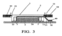
図3は、図1及び2に示されているようなタッチセンサ式表示器又はタッチパッド実装用のタッチスクリーン組立品2の断面図であり、PSL3が電子装置の機械的全体カバー20内に収容される様子を示している。この実施形態では、レンズ3には装置の機械的筐体20の下へ突出する舌部及び溝縁部21が形成される。これは、PSLレンズ3の脱落を防止し、押し下げられたとき下方へ自由に移動できるようにする。筐体20とレンズ3との間の領域にはゴム製の詰め物9が有り、レンズ3の移動を制限し、衝撃や振動を緩和し、ゴミやチリに対して装置を密封する。PSL3は、下方に延びて主装置回路基板30との間に検知器7を挟む側部フランジを含んでいる。印加圧力0から印加圧力最大値までの移動量については、ゴム製詰め物9で可能な最大可能移動量は、典型的には0.01〜0.1mmである。
FIG. 3 is a cross-sectional view of a
装置が逆さまにされた場合でもタッチスクリーン組立品2が完全に機能するように、検知器7は、予め負荷がかけられている。これは、検知器7がPSL3の重量より大きく均等な力でPSL3と予め係合することを伴い、4個の検知器を常に係合させる。FSR検知器の場合、これは特に重要である。各FSR検知器7に予め所定の負荷をかけることにより、常に係合が保たれ、極く小さな印加力でも制御された反復可能な検知器出力を生じ、タッチ座標が容易に決定できるようにする。
The detector 7 is pre-loaded so that the
加えて、長さが調整された支柱(pylons)13を用い、レンズ3の下方に延ばし、許容可能な最大移動量を制限し、検知器7の過圧縮を防止するための留め具として機能させる。この支柱13は、FSR検知器7の場合には任意であるが、伝統的なピエゾ抵抗検知器を使用する場合には必須である。
In addition, a length-adjusted
検知器7は、携帯電話又は他の電子装置の主回路基板と直接に結合するコネクタ18に接続する可撓性フィルム14で接続されており、所望であれば周辺部品40を可撓性フィルム14の上に搭載することができる。差動搭載される4個の圧力検知器7は、装置の印刷回路基板30の上、又はLCD若しくはOLEDモジュールの下に直接実装することができ、両者については以下で説明する。当業者には明らかなように、より伝統的な電線、多数の印刷回路基板又はこれらの組合わせを可撓性フィルム14とコネクタ18に代えて使用できる。
The detector 7 is connected by a
各圧力検知器7は、典型的には金属導電部ないし配線上に高分子を付けたものである力検知抵抗(FSR)を含むことが好ましい。FSR検知器は、検知器7に加えられる力を測定するために電気的抵抗特性を利用する。複数個(例えば4個等)の差動搭載された検知器7があると、各検知器は、レンズ2平面に沿った2次元(x、y)座標の関数として異なる力を登録する。隅の差動的な圧力を計算し、実際にタッチされた正確な座標を計算できる。
Each pressure detector 7 preferably includes a force sensing resistor (FSR) that is typically a metal conductive part or wiring with a polymer attached. The FSR detector uses electrical resistance characteristics to measure the force applied to the detector 7. When there are a plurality of (for example, four) differentially mounted detectors 7, each detector registers a different force as a function of two-dimensional (x, y) coordinates along the
図4は、個々のFSR検知器7の概略図を示しており、公知のインキないし高分子である感圧可変抵抗材料76に印刷された一対の導電性配線72、74を含む。抵抗材料76は、2つの配線72、74間に可変の電気的経路を生成する。検知器7に力が加えられると、材料76の抵抗が減少する。
FIG. 4 shows a schematic diagram of an individual FSR detector 7 and includes a pair of
図5は、力(g)の関数としての検知器7の抵抗(キロオーム)を示す。検知器動作の3区域に留意することが重要である。第1は、力が10ないし100gの圧力範囲内で起こる急激な変化である。これより上では、力が飽和までほぼ比例し、飽和点では力を増しても抵抗値が減少しない。統合FSR検知器を用いることの効果は、電圧出力が、典型的には、ピエゾ抵抗力検知器の電圧出力の10倍になることである。この高い電圧のためにアナログ信号増幅器を追加する必要がなくなり、これによって必要な基板の大きさと部品費用の双方を更に削減することとなる。FSR検知器を使用することにより機械的な設計が更に単純化されるが、これは、これらの検知器が典型的なピエゾ抵抗検知器と異なり過大圧力に対して保護する必要がないためである。上記のように、装置が逆さまにされた場合でもタッチスクリーン組立品2が完全に機能するように、各検知器7には予め制御された負荷がかけられている。図5に示されているように、印加される初期の力は、何らの電圧出力も極めて不規則な出力も生じない。各FSR検知器7に予め極めて制御された負荷をかけることにより、FSR検知器7は、常に係合が保たれ、極く小さな印加力でも制御された反復可能な検知器出力を生じ、タッチ座標を容易に決定できるようにする。
FIG. 5 shows the resistance of the detector 7 (kiloohms) as a function of force (g). It is important to note the three areas of detector operation. The first is an abrupt change where the force occurs within a pressure range of 10 to 100 g. Above this, the force is approximately proportional to saturation, and the resistance does not decrease at the saturation point even if the force is increased. The effect of using an integrated FSR detector is that the voltage output is typically 10 times that of a piezoresistive force detector. This high voltage eliminates the need for additional analog signal amplifiers, thereby further reducing both the required board size and component costs. The use of FSR detectors further simplifies the mechanical design because these detectors do not need to be protected against overpressure unlike typical piezoresistive detectors. . As described above, a pre-controlled load is applied to each detector 7 so that the
図2の挿入図に戻ると、検知器7は、装置の印刷回路基板30の上というより、むしろLCDないしOLEDモジュール5の下に取り付けられている。これは、LCDないしOLEDモジュール5の下に導電材料層82を加えることにより達成される。そこで、必要なら間隔片84とFSR抵抗性高分子85が導電材料82に接するように付加される。機能向上のために、ポロン(Poron 、商標)のような或る種の裏打ち材料が検知器7に加えられる。導電性配線は、導電材料82に沿って走り、汎用FSR設計毎に(4個の検知器毎に)可撓性フィルム6に接続されるか、又は別の可撓性フィルムコネクタによって主装置回路基板30に接続される。そして、この構成により、LCDないしOLEDモジュール5に予めユニットとして統合された4個のFSR検知器7全てを設けることができる。
Returning to the inset of FIG. 2, the detector 7 is mounted below the LCD or OLED module 5 rather than on the printed
検知器7をLCDないしOLEDモジュール5へ統合することの代替案として、図6は、検知器7を主装置PCB板30に搭載する方法を示している。ここでは、導電材料層82は、下のPCB30に接着されるか、又はPCB30に直接エッチングされる。PCB30は、2つの指状導電配線(図4の72、74)として設計されている。この配線領域の上に搭載されているのは間隔片98(挿入図参照)と感圧可変抵抗材料76であり、更にLCDないしOLEDモジュール5の下側に実装されている。加えて、この実装では、LCDないしOLEDモジュール5は、僅かに出っ張った筒状脚部100を所謂「活性剤」(FSR検知器の表面がシリコーンで被覆され、軸方向圧縮時にFSRを活性化することは、一般に知られている。)として備えている。「活性剤」は、FSR検知器材料をより長い距離で圧縮することを可能とし、解像度を上げ、検知器のダイナミックレンジを大きくすることを保証する。可撓性フィルム14は、携帯電話や他の電子装置の主回路板と直接結合する可撓性フィルムコネクタ18まで延び、所望であれば周辺部品40を可撓性フィルム14上に搭載できる。
As an alternative to integrating the detector 7 into the LCD or OLED module 5, FIG. 6 shows a method of mounting the detector 7 on the main
留意すべきは、図2(挿入図)及び図6に示された統合手法のいずれでも、装置全体の積み重ねの高さが増加していないことである。なぜなら、携帯電話のような装置ではLCDないしOLEDモジュール5がPSLレンズ3で保護されているからである。LCDないしOLEDモジュール5とその下のPCB30との間の高さでFSR7によって増加する高さは、使用材料に応じて約0.30から0.80mmである。しかしながら、典型的な携帯電話設計では、この間隔95は、薄型部品の配置を可能とするよう一般に高さ1.25mmに設計されている。結果的に、現在の組立品の高さの増加は、それ故皆無である。
It should be noted that neither of the integration techniques shown in FIG. 2 (inset) and FIG. 6 increased the stack height of the entire device. This is because the LCD or OLED module 5 is protected by the
FSR検知器の代替手段として、より伝統的な圧力検知器、例えばピエゾ抵抗力検知器を用いることもできる。これらは、一般に機械部品と変換器を含む。複数個(例えば4個等)の商業的に利用可能な微小力検知器は、検知器7として役立つ。これらは、1N未満の力を検知できる、7.0×5.2×2.9mmのセラミックパッケージで利用可能である。これらは、圧力変化に応答して撓むシリコン素子に頼っており、内部ブリッジ回路を介して比例出力信号を生成する。 As an alternative to FSR detectors, more traditional pressure detectors such as piezoresistive force detectors can also be used. These generally include mechanical parts and transducers. A plurality (e.g. 4) of commercially available micro force detectors serve as the detector 7. They are available in a 7.0 x 5.2 x 2.9 mm ceramic package that can detect forces below 1 N. They rely on silicon elements that flex in response to pressure changes and produce a proportional output signal via an internal bridge circuit.
図7は、伝統的な圧力検知器170に使用される機械的組立品の例であり、柱173のさやに閉じこめられている金属小球171と係合する機械的変換器172を含む。球171は、主PCB30又は装置の任意の機械部品である下側の面に当たり、レンズ組立品2の上部にあるPSL3に圧力が加えられたとき変換器172に押しつけられる。表示器がタッチされていないとき、特に感度の高い圧力検知器が用いられている場合に力を登録しないよう、レンズ組立品2は、柱173のさや内等のレンズ組立品2内に統合された通常の螺旋ばねで、又は他のばねシステム若しくはゴムや発泡体のような緩衝材で、ばね負荷がかけられる。好ましくは、レンズ組立品2の運動は、損傷を防止するため部品16底部で制限される。
FIG. 7 is an example of a mechanical assembly used in a traditional pressure detector 170 that includes a mechanical transducer 172 that engages a metal ball 171 confined to the pod of a
図8は、組立品の動作を示す流れ図である。本装置の周辺電子部品は、各圧力検知器7、170に接続された増幅器、例えばアナログデバイセズ社のAD623、及びアナログデバイセズ社のAD7888のような増幅器に接続されたA/D変換器を含む。これら全ての周辺的な抵抗、電源等は、要望に応じて主装置PCB30又は可撓性PCB6、14に搭載できる。
FIG. 8 is a flowchart showing the operation of the assembly. Peripheral electronic components of the device include an A / D converter connected to an amplifier, such as an Analog Devices AD623, and an Analog Devices AD7888, connected to each pressure detector 7,170. All of these peripheral resistors, power supplies, etc. can be mounted on the
各圧力検知器7、170の出力は、電圧出力が小さい場合には増幅され、ステップ72でデジタル変換(A/D変換)され、装置のホストプロセッサ又は専用マイクロプロセッサに常駐しているソフトウエアの力検知器ドライバ74に渡される。ソフトウエア力検知器ドライバ74は、不適切な入力を除去するために選別を行い、力データの正確性を最大化する。例えば使用者が装置を持って歩いている場合、衝撃によりレンズ3が検知器7を押すことがある。この種のジッターは、キー押下とは異なる「指紋」を持ち、除去される。差動搭載された全検知器7からのデータは、結合され、較正調整(起動時に実行される独立した使用者較正用アプリケーションにより予め記録されている。)によって補正され、x、y座標が計算される。計算は、より正確性を高めるために時間に基いている。この結果、データ点の時間的系列が各キー押下により得られる。力の小さな値すなわち時間的系列の初期における値及び終期における大きな力の値は除去され、残ったデータ点が最終的なx、y座標平均の計算に使用される。代替的には、ピークの力を有するデータ標本だけを座標計算に用いることができ、又は力の合計を平均計算におけるx、y値の重み付けに用いることができる。所望なら、力の実際の値又は平均値を後で利用するために記録することもできる。
The output of each pressure detector 7, 170 is amplified if the voltage output is small, digitally converted (A / D conversion) in
上記のように検知器7に予め負荷がかけられる場合、予めかける負荷力に対する調整が行われる。例えば、所与の複数個n=1・・・m個の圧力検知器がPSL3の下に実装され、x軸とy軸に沿って差動的に位置し、各圧力検知器が予めかける負荷力p1−mで圧縮されているとすると、x軸とy軸に沿った任意の位置での接触による補償圧力Pc1−mは、Pc1−m=z1−m−p1−mとなる。これは、データ集合(x1−m,y1−m,Pc1−m)の時間的系列となる。 As described above, when a load is applied to the detector 7 in advance, adjustment to the load force applied in advance is performed. For example, a given plurality of n = 1... M pressure detectors are mounted under PSL3, are positioned differentially along the x-axis and y-axis, and each pressure detector is preloaded. Assuming that the pressure is compressed by the force p 1-m , the compensation pressure Pc 1-m due to contact at an arbitrary position along the x-axis and the y-axis is Pc 1-m = z 1-m -p 1-m It becomes. This is a time series of the data set (x 1-m , y 1-m , Pc 1-m ).
ソフトウエア力検知器ドライバ74の出力は、x、y座標であり、その後ホストプロセッサに常駐するマウスイベント列80に入力され、任意的であるが、触覚ソフトウエアドライバ82に送られ、表示器が押下されたとき使用者触覚フィードバックを発生するために触覚装置12(図2)に送られる。
The output of the software
図9は、タッチセンサ式表示器又はタッチパッド実装用の感圧レンズ組立品2の断面図である。PSL組立品2は、例えば.030ポリカーボネート又は熱安定ポリエステルで形成された上部透明レンズ3を含む。レンズ3は、必要な電子部品と機械的部品の全てをその下面や周辺に持っており、好ましくは全ての面実装用回路部品が裏面で薄膜可撓性フイルムPCBに搭載され、電気配線が可撓性フィルム14を介して4個の差動搭載圧力検知器175に接続されている。当業者であれば容易に理解できることであるが、より伝統的な電線、印刷回路基板又はその組合わせを可撓性フィルムとコネクタの替わりに使用することができる。ここで、可撓性フィルム14は、携帯電話又は他の電子装置の主回路基板と直接に結合する可撓性フィルムコネクタ18まで延びている。留意すべきは、圧力検知器175が直交して透明レンズ3から後方に搭載された内蔵型装置となっていることである。各圧力検知器175は、上記のように機械部品と変換器を含む。更に、複数個(例えば4個等)の商業的に利用可能な微小力検知器は、変換器として役立つ。圧力検知器の変換器は、柱内に閉じこめた金属小球に連動する。圧力がPSLレンズ3の頂部に加えられたとき、球は、主PCB又は装置の任意の機械部品である下部の面30に当接し、変換器上に押しつけられる。複数個(例えば4個等)の差動搭載検知器175を考えると、各検知器は、レンズ3の面に沿った2次元(x,y)座標の関数として異なる力を登録する。隅の差動的圧力を計算することにより、実際の接触の正確な座標を計算できる。表示器が触れられていないとき、特に感度の高い圧力検知器が用いられている場合に力が登録されないようにするために、レンズ組立品2は、上記のように、ばね負荷がかけられている。
FIG. 9 is a cross-sectional view of the pressure-
図10では、機械的筐体20が無いタッチ組立品2を上から見ている。下側にある表示器5は、組立品のレンズ3を通して見ることができる。電気コネクタ14は、可撓性フィルムレンズ3上に形成され、通常は外部構造で覆われている領域へ、ここでは表示器5に沿って通る。この実施形態では、複数の圧力検知器175は、可撓性フィルム配線コネクタ14を介して、また増幅器等の周辺電気部品を介して下方のホストプロセッサPCBに接続される。前記実施形態のレンズ3が機械的筐体20に固定されていないという事実から、機械的筐体20から独立して振動させることが可能となる。これにより、現在の構成が触覚フィードバック用圧電素子追加に特に適したものとなる。また、圧電素子12は、可撓性フィルム14を介して接続され、組立品中に含まれる。統合圧電素子12は、使用者に対するフィードバック、触覚フィードバックないし音響フィードバックを生じることができる。使用者がレンズに触れると、制御ユニットは、接触を検知し、以後の処理のために座標を送信する。同時に、圧電素子12は、5ないし50ミリ秒等の短期間振動するよう指令される。レンズ組立品2は装置筐体20に極く緩く結合されているだけであるので、比較的容易に振動することができ、使用者は、タッチ指令の効果を見ることはできないが、実際にキーが押下されキー押下が登録されたことのフィードバックを指への振動の形態で即座に得る。当業者であれば理解できるように、他の種類の部品(圧電以外)、例えば、ダーフォン・エレクトロニクス・コープ(Darfon Electronics Corp.)のSMD誘導コイルのような、磁気素子を振動させるように接続された誘導磁気コイル等を用いることができる。触覚素子に加えて、デジタルアナログ変換器や増幅器のような付加的な電子部品を可撓性フィルム14に搭載することもできる。コイルでなく圧電素子を使用する効果は、圧電素子が触覚発生器とスピーカの二役を果たすことである。触覚素子の2形態であるコイルと圧電素子は、携帯電話の着信報知振動用の独立した振動器に代わることができる。
In FIG. 10, the
図11は、上記PSL2に2次元又は3次元の運動検知器40を加えたものを示している。運動検知器40は、レンズ組立品の可撓性フィルム14を介してホストPCB42に同様に接続されている。運動検知器40は、好ましくは商業的に利用可能なMEMs運動検知器、アナログ・デバイセズ社(Analog Device's、商標)の3軸iMEMS(統合MEMS)運動信号処理検知器等であり、単一の低電力チップで超小型低電力3軸(x−y−z)検知を可能とする。これにより携帯装置は、位置、方向及び運動に対して知的に応答することが可能となる。より具体的にいうと、装置使用者の運動を登録でき、装置制御における入力として用いることができる。例えば、使用者は、キー押下ではなく運動により、大きな仮想表示器上で大きくスクロールしたり、拡大縮小したりできる。この種の運動によるユーザーインターフェース制御の原理は、PCT公報のWO0127735号に記載されており、この参照によってここに組み込まれる。
FIG. 11 shows a structure in which a two-dimensional or three-
図12は、更に他の実施形態を示しており、表示器51が共有可撓性フィルム53を介して同様に接続され、表示器51とPSL2の双方が1以上の可撓性フィルムコネクタ52を介して共にPCB50に接続されている。この結果、表示器51からの可撓性フィルム53は、可撓性フィルムで組立品全体に接続されている。また、本実施形態は表示器51のバックライトを含み、表示器バックライトの電源用に専用電源54が可撓性フィルム53上に搭載されている。バックライトは、独立部品として表示器背後に搭載されてもよく、また表示器又はPSL組立品2に統合されていてもよく、この場合にはバックライトは、レンズの下に滑り込まされている。
FIG. 12 shows yet another embodiment in which the display 51 is similarly connected via a shared flexible film 53, and both the display 51 and PSL2 have one or more flexible film connectors 52. Both are connected to the
当業者であれば理解できるように、上記実施形態の統合感圧レンズ組立品は、統合のために単純化し、これによって最終製品化のための実装費用と時間を低下させ、また組立品を使用した製品を市場に出す時間を短縮するという観点で更に最適化することができる。これは、ホストプロセッサ搭載の上記ソフトウエアを、統合メモリ(又は独立部品メモリ)を有しレンズ組立品の可撓性フイルム14(図7参照)上に直接載置された単体型プロセッサに実装することにより可能である。この場合、上述の位置計算は、装置のホストプロセッサより寧ろ単体型プロセッサによって実行される。この場合の効果は、ソフトウエア統合の必要性が大幅に減少し、部分組立品と装置の他部分との通信がホストプロセッサ上で動く単純な通信用アプレットで行い得ることである。この場合の通信内容は、「x」座標と「y」座標、表示器からの割り込みや「目覚まし」コール、及び力の大きさを示す「z」値である。 As will be appreciated by those skilled in the art, the integrated pressure-sensitive lens assembly of the above embodiment simplifies for integration, thereby reducing mounting costs and time for final product and using the assembly. This can be further optimized in terms of reducing the time it takes to place the product on the market. This is implemented by mounting the above-mentioned software loaded on the host processor on a single processor that has an integrated memory (or independent component memory) and is placed directly on the flexible film 14 (see FIG. 7) of the lens assembly. Is possible. In this case, the position calculation described above is performed by a single processor rather than the host processor of the apparatus. The effect in this case is that the need for software integration is greatly reduced and communication between the subassembly and the rest of the device can be done with a simple communication applet running on the host processor. The communication contents in this case are “x” and “y” coordinates, an interrupt from the display or “wake-up” call, and a “z” value indicating the magnitude of the force.
図2に示されているように、レンズは、機構的な積み重ねの基礎を形成しており、可撓性フィルムと部品を加えることができる。機械的な制約が携帯電話ほど厳しくない、例えばラップトップPC又はタブレットPC用の実装では、組立は完全にモジュール化され、設計と組立が単純化されている。 As shown in FIG. 2, the lens forms the basis for a mechanistic stack, and flexible films and components can be added. In implementations where the mechanical constraints are not as stringent as mobile phones, for example laptop or tablet PCs, the assembly is completely modular and the design and assembly is simplified.
ここで、上述の発明の各実施形態が携帯電話やPDA等の携帯電子装置の製造に適した低価格感圧タッチセンサー式表示器の解決法を提供していることは明らかである。本装置は、完成品形式の解決法であるので、既存電子装置の費用や形状因子を損なうことなく製品の全体設計に取り込むことができる。 Here, it is clear that the embodiments of the invention described above provide a solution for a low-cost pressure-sensitive touch-sensitive display suitable for the manufacture of portable electronic devices such as mobile phones and PDAs. Since this device is a solution in the form of a finished product, it can be incorporated into the overall design of the product without compromising the cost and form factor of existing electronic devices.
本発明の好適な実施形態と特定の変更について既に十分に説明したが、当業者であれば、この基本概念を知悉することにより、これに対する幾つかの変形や変更と共に他の種々の実施形態に容易に想到することができる。したがって、当然のことながら、本発明は、ここに具体的に説明したもの以外の態様で実施することもできる。 Although the preferred embodiments and specific modifications of the present invention have already been fully described, those skilled in the art will be aware of this basic concept in various other embodiments along with some variations and modifications thereto. It can be easily conceived. Thus, it will be appreciated that the invention may be practiced otherwise than as specifically described herein.
タッチスクリーンは、ますます多くの製品で採用されてきており、数種の技術系列が用いられている。製品の大きさが縮小し続けるにつれて、安価で、薄型で正確なタッチスクリーンに対する要望が増加している。実際に小型電子装置に使用する場合、検知器は、薄型で、すなわち最大厚さが約0.508mm(20 mils)より薄くなければならず、また、事実上「スナップイン」構造としてモジュール組み立て可能とすべきである。今日の電子産業では、感圧タッチセンサ式表示器の解決法を用いる電子装置の製造者は、製品の全体設計に容易に統合できる完全な解決法を表示器供給者に求める。ここに挙げた既存検知技術の有用性にも関わらず、従来技術は、十分な感度、表面堅牢性、精度及び形状因子を持つ安価な検知器組立品を提供することができなかった。したがって、従来技術の幾つかの欠点を克服した力検知技術を提供する本発明には、重要な産業上の利用可能性が存する。 Touch screens are being adopted by more and more products, and several types of technology are used. As product sizes continue to shrink, there is an increasing demand for inexpensive, thin and accurate touch screens. For practical use in small electronic devices, the detector must be thin, i.e. the maximum thickness should be less than about 20 mils, and can be virtually modularized as a "snap-in" structure Should be. In today's electronics industry, manufacturers of electronic devices using pressure sensitive touch sensitive display solutions require display suppliers to have a complete solution that can be easily integrated into the overall product design. Despite the usefulness of the existing detection technologies listed here, the prior art failed to provide an inexpensive detector assembly with sufficient sensitivity, surface robustness, accuracy and form factor. Thus, the present invention which provides force sensing technology that overcomes some of the disadvantages of the prior art has significant industrial applicability.
Claims (22)
前記表示器モジュール上のレンズ、
前記表示器モジュールの下に搭載され、x軸とy軸に沿って差動的に位置する複数個n=1・・・m個の差動搭載圧力検知器であって、電子装置に電気接続され、前記x軸とy軸に沿った任意の位置における前記レンズの接触から圧力zを登録し、アナログ差動圧力信号を生じる圧力検知器、
前記アナログ差動圧力信号をデータ集合(x1−m,y1−m,z1−m)の時間的系列に変換する回路、及び
前記データ集合(x1−m,y1−m,z1−m)の時間的系列を解釈かつ選別して正確な接触座標を生じ、前記接触座標にしたがって制御信号を発生する制御用ソフトウエア
を含む電子装置用タッチスクリーン組立品。 A touch screen assembly for an electronic device having an LCD or OLED display module,
A lens on the display module;
A plurality of n = 1... M differentially mounted pressure detectors mounted under the display module and positioned differentially along the x-axis and y-axis, and electrically connected to the electronic device A pressure detector that registers the pressure z from contact of the lens at any position along the x-axis and y-axis to produce an analog differential pressure signal;
A circuit for converting the analog differential pressure signal into a time series of a data set (x 1-m , y 1-m , z 1-m ), and the data set (x 1-m , y 1-m , z A touch screen assembly for an electronic device including control software that interprets and sorts the time sequence of 1-m ) to generate accurate contact coordinates and generates a control signal according to the contact coordinates.
前記表示器上で1自由度を有する浮動レンズ、
前記浮動レンズの少なくとも一部の下に取り付けられた下部可撓性フィルム接続層、
前記浮動レンズの下に搭載され、x軸とy軸に沿って差動的に位置する4個の差動搭載圧力検知器であって、前記接続層で電子装置に電気接続され、前記4位置の各々における前記レンズの接触から圧力zを登録し、4個のデータ集合(x1−4,y1−4,z1−4)を生じる圧力検知器、
前記4個のデータ集合から正確な接触座標を解釈し、前記接触座標にしたがって制御信号を発生する制御用ソフトウエア
を含む電子装置用タッチスクリーン組立品。 A touch screen assembly for an electronic device having a display,
A floating lens having one degree of freedom on the display;
A lower flexible film connection layer attached under at least a portion of the floating lens;
Four differential mounting pressure detectors mounted under the floating lens and positioned differentially along the x-axis and y-axis, electrically connected to an electronic device at the connection layer, the four positions A pressure detector that registers the pressure z from the contact of the lens in each of the two and generates four data sets (x 1-4 , y 1-4 , z 1-4 ),
An electronic device touch screen assembly including control software that interprets accurate contact coordinates from the four data sets and generates control signals according to the contact coordinates.
前記表示器モジュール上のレンズ、
前記レンズの下に搭載され、x軸とy軸に沿って差動的に位置する複数個n=1・・・m個の圧力検知器であって、各々が予めかける負荷力p1−mで圧縮され、電子装置に電気接続され、前記x軸とy軸に沿った任意の位置における前記レンズの接触から、補償圧力Pc1−m=z1−m−p1−mを登録し、アナログ差動圧力信号を生じる圧力検知器、
前記アナログ差動圧力信号をデータ集合(x1−m,y1−m,Pc1−m)の時間的系列に変換する回路、及び
前記データ集合(x1−m,y1−m,Pc1−m)の時間的系列を解釈かつ選別して正確な接触座標を生じ、前記接触座標にしたがって制御信号を発生する制御用ソフトウエア
を含む電子装置用タッチスクリーン組立品。 A touch screen assembly for an electronic device having an LCD or OLED display module,
A lens on the display module;
A plurality of n = 1... M pressure detectors mounted under the lens and positioned differentially along the x-axis and y-axis, each of which has a load force p 1-m applied in advance. in compressed, electrically connected to the electronic device, the contact of the lens at any position along the x-axis and y-axis, and registers the compensating pressure Pc 1-m = z 1- m -p 1-m, A pressure detector that produces an analog differential pressure signal,
A circuit for converting the analog differential pressure signal into a time series of a data set (x 1-m , y 1-m , Pc 1-m ), and the data set (x 1-m , y 1-m , Pc) A touch screen assembly for an electronic device including control software that interprets and sorts the time sequence of 1-m ) to generate accurate contact coordinates and generates a control signal according to the contact coordinates.
Applications Claiming Priority (2)
| Application Number | Priority Date | Filing Date | Title |
|---|---|---|---|
| US84311606P | 2006-09-09 | 2006-09-09 | |
| PCT/US2007/019606 WO2008030594A2 (en) | 2006-09-09 | 2007-09-07 | Integrated pressure sensitive lens assembly |
Publications (1)
| Publication Number | Publication Date |
|---|---|
| JP2010503113A true JP2010503113A (en) | 2010-01-28 |
Family
ID=39157884
Family Applications (1)
| Application Number | Title | Priority Date | Filing Date |
|---|---|---|---|
| JP2009527441A Pending JP2010503113A (en) | 2006-09-09 | 2007-09-07 | Integrated pressure-sensitive lens assembly |
Country Status (6)
| Country | Link |
|---|---|
| US (1) | US8269731B2 (en) |
| EP (1) | EP2062119A4 (en) |
| JP (1) | JP2010503113A (en) |
| KR (1) | KR20090077755A (en) |
| CN (1) | CN101512468A (en) |
| WO (1) | WO2008030594A2 (en) |
Cited By (7)
| Publication number | Priority date | Publication date | Assignee | Title |
|---|---|---|---|---|
| JP2013254529A (en) * | 2008-09-17 | 2013-12-19 | Nec Corp | Input device, control method thereof and electronic equipment provided with input device |
| US8738133B2 (en) | 2006-12-20 | 2014-05-27 | Cardiac Pacemakers, Inc. | Rate adaptive cardiac pacing systems and methods |
| JP2017538187A (en) * | 2014-10-30 | 2017-12-21 | ビーボップ センサーズ、インコーポレイテッド | Sensor system integrated with globe |
| US10802641B2 (en) | 2012-03-14 | 2020-10-13 | Bebop Sensors, Inc. | Piezoresistive sensors and applications |
| US10884496B2 (en) | 2018-07-05 | 2021-01-05 | Bebop Sensors, Inc. | One-size-fits-all data glove |
| US11147510B2 (en) | 2014-06-09 | 2021-10-19 | Bebop Sensors, Inc. | Flexible sensors and sensor systems |
| US11480481B2 (en) | 2019-03-13 | 2022-10-25 | Bebop Sensors, Inc. | Alignment mechanisms sensor systems employing piezoresistive materials |
Families Citing this family (116)
| Publication number | Priority date | Publication date | Assignee | Title |
|---|---|---|---|---|
| JP2017073100A (en) | 2015-10-05 | 2017-04-13 | 株式会社ミライセンス | Tactile and force information providing system |
| US7688237B2 (en) * | 2006-12-21 | 2010-03-30 | Broadcom Corporation | Apparatus and method for analog-to-digital converter calibration |
| US9329719B2 (en) * | 2007-03-15 | 2016-05-03 | Apple Inc. | Hybrid force sensitive touch devices |
| US8199033B2 (en) * | 2007-07-06 | 2012-06-12 | Pacinian Corporation | Haptic keyboard systems and methods |
| US7741979B2 (en) * | 2007-07-06 | 2010-06-22 | Pacinian Corporation | Haptic keyboard systems and methods |
| US20100127140A1 (en) * | 2008-01-23 | 2010-05-27 | Gary Smith | Suspension for a pressure sensitive touch display or panel |
| US8310444B2 (en) * | 2008-01-29 | 2012-11-13 | Pacinian Corporation | Projected field haptic actuation |
| US8294600B2 (en) * | 2008-02-15 | 2012-10-23 | Cody George Peterson | Keyboard adaptive haptic response |
| CA2714534C (en) * | 2008-02-28 | 2018-03-20 | Kenneth Perlin | Method and apparatus for providing input to a processor, and a sensor pad |
| US8203531B2 (en) | 2008-03-14 | 2012-06-19 | Pacinian Corporation | Vector-specific haptic feedback |
| WO2009143267A2 (en) * | 2008-05-20 | 2009-11-26 | Qsi Corporation | Stress-limiting device for forced-based input panels |
| US8385885B2 (en) | 2008-10-17 | 2013-02-26 | Sony Ericsson Mobile Communications Ab | Method of unlocking a mobile electronic device |
| JP5181093B2 (en) * | 2008-12-08 | 2013-04-10 | 韓國電子通信研究院 | Touch screen and operation method thereof |
| EP2202619A1 (en) * | 2008-12-23 | 2010-06-30 | Research In Motion Limited | Portable electronic device including tactile touch-sensitive input device and method of controlling same |
| US8384679B2 (en) | 2008-12-23 | 2013-02-26 | Todd Robert Paleczny | Piezoelectric actuator arrangement |
| CN102388354A (en) * | 2009-02-17 | 2012-03-21 | 诺亚·安格林 | Floating plane touch detection system |
| US20100225600A1 (en) * | 2009-03-09 | 2010-09-09 | Motorola Inc. | Display Structure with Direct Piezoelectric Actuation |
| WO2010113698A1 (en) * | 2009-03-31 | 2010-10-07 | 日本写真印刷株式会社 | Information input device and pressure detection unit used for information input device |
| US8260377B2 (en) | 2009-05-07 | 2012-09-04 | Research In Motion Limited | Gasket for a mobile device having a touch sensitive display |
| ATE526624T1 (en) * | 2009-05-07 | 2011-10-15 | Research In Motion Ltd | SEAL FOR A MOBILE DEVICE HAVING A TOUCH-SENSITIVE DISPLAY |
| US9430078B2 (en) * | 2009-08-12 | 2016-08-30 | Google Technology Holdings LLC | Printed force sensor within a touch screen |
| CN201548948U (en) * | 2009-11-09 | 2010-08-11 | 瑞声声学科技(深圳)有限公司 | Touch screen feedback device |
| TWI420197B (en) * | 2010-01-21 | 2013-12-21 | Tpk Touch Solutions Inc | Embedded touch sensitive display and a method of manufacturing the same |
| JP5805974B2 (en) * | 2010-03-31 | 2015-11-10 | ティーケー ホールディングス,インコーポレーテッド | Steering wheel sensor |
| US8983732B2 (en) | 2010-04-02 | 2015-03-17 | Tk Holdings Inc. | Steering wheel with hand pressure sensing |
| CN102123561B (en) * | 2010-04-19 | 2013-12-25 | 苹果公司 | Electronic sub-component used for electronic device |
| JP2012034064A (en) * | 2010-07-28 | 2012-02-16 | Kyocera Corp | Portable electronic apparatus |
| CN103210363B (en) * | 2010-09-12 | 2015-08-05 | 深圳纽迪瑞科技开发有限公司 | Pressure sensor device and method of operating |
| US8508927B2 (en) | 2010-09-24 | 2013-08-13 | Research In Motion Limited | Gasket and display assembly for an electronic mobile device |
| US9971405B2 (en) * | 2010-09-27 | 2018-05-15 | Nokia Technologies Oy | Touch sensitive input |
| US8543168B2 (en) * | 2010-12-14 | 2013-09-24 | Motorola Mobility Llc | Portable electronic device |
| DE102011009840A1 (en) * | 2011-01-31 | 2012-08-02 | Continental Automotive Gmbh | operating device |
| US9389721B2 (en) | 2011-02-09 | 2016-07-12 | Apple Inc. | Snap domes as sensor protection |
| DE102011011769A1 (en) | 2011-02-18 | 2012-08-23 | Fresenius Medical Care Deutschland Gmbh | Medical device with touch screen and procedure |
| US9692411B2 (en) | 2011-05-13 | 2017-06-27 | Flow Control LLC | Integrated level sensing printed circuit board |
| US10180722B2 (en) * | 2011-05-27 | 2019-01-15 | Honeywell International Inc. | Aircraft user interfaces with multi-mode haptics |
| US9411442B2 (en) | 2011-06-29 | 2016-08-09 | Google Technology Holdings LLC | Electronic device having managed input components |
| US8890823B2 (en) * | 2012-01-09 | 2014-11-18 | Motorola Mobility Llc | System and method for reducing occurrences of unintended operations in an electronic device |
| BR202012004686Y1 (en) | 2011-07-13 | 2019-05-14 | Google Technology Holdings LLC | MOBILE ELECTRONIC DEVICE WITH ENHANCED IMPACT REDUCTION. |
| KR200471325Y1 (en) * | 2011-07-13 | 2014-02-19 | 모토로라 모빌리티 엘엘씨 | Mobile electronic device with enhanced tolerance accumulator |
| BR202012004685Y1 (en) | 2011-07-13 | 2019-04-02 | Google Technology Holdings LLC | MOBILE ELECTRONIC DEVICE WITH IMPROVED LAMINATED CONSTRUCTION |
| BR202012004687U8 (en) | 2011-07-13 | 2016-11-22 | Motorola Mobility Inc | MOBILE ELECTRONIC DEVICE WITH IMPROVED CHASSIS |
| US9417754B2 (en) | 2011-08-05 | 2016-08-16 | P4tents1, LLC | User interface system, method, and computer program product |
| US9495952B2 (en) | 2011-08-08 | 2016-11-15 | Qualcomm Incorporated | Electronic devices for controlling noise |
| DE102011084903A1 (en) | 2011-10-20 | 2013-04-25 | TAKATA Aktiengesellschaft | Sensor systems for a motor vehicle |
| US8922523B2 (en) * | 2011-11-29 | 2014-12-30 | Apple Inc. | Embedded force measurement |
| CN103135906A (en) * | 2011-12-02 | 2013-06-05 | 英华达(上海)科技有限公司 | Screen display control system and method of screen display control system |
| US8878788B2 (en) * | 2012-01-09 | 2014-11-04 | Motorola Mobility Llc | Touch screen device with surface switch |
| US9354748B2 (en) | 2012-02-13 | 2016-05-31 | Microsoft Technology Licensing, Llc | Optical stylus interaction |
| US9360893B2 (en) | 2012-03-02 | 2016-06-07 | Microsoft Technology Licensing, Llc | Input device writing surface |
| US9870066B2 (en) | 2012-03-02 | 2018-01-16 | Microsoft Technology Licensing, Llc | Method of manufacturing an input device |
| US9298236B2 (en) | 2012-03-02 | 2016-03-29 | Microsoft Technology Licensing, Llc | Multi-stage power adapter configured to provide a first power level upon initial connection of the power adapter to the host device and a second power level thereafter upon notification from the host device to the power adapter |
| USRE48963E1 (en) | 2012-03-02 | 2022-03-08 | Microsoft Technology Licensing, Llc | Connection device for computing devices |
| US9064654B2 (en) | 2012-03-02 | 2015-06-23 | Microsoft Technology Licensing, Llc | Method of manufacturing an input device |
| US9075566B2 (en) | 2012-03-02 | 2015-07-07 | Microsoft Technoogy Licensing, LLC | Flexible hinge spine |
| US9426905B2 (en) | 2012-03-02 | 2016-08-23 | Microsoft Technology Licensing, Llc | Connection device for computing devices |
| US9460029B2 (en) | 2012-03-02 | 2016-10-04 | Microsoft Technology Licensing, Llc | Pressure sensitive keys |
| WO2013154720A1 (en) | 2012-04-13 | 2013-10-17 | Tk Holdings Inc. | Pressure sensor including a pressure sensitive material for use with control systems and methods of using the same |
| US20130300590A1 (en) | 2012-05-14 | 2013-11-14 | Paul Henry Dietz | Audio Feedback |
| US10031556B2 (en) | 2012-06-08 | 2018-07-24 | Microsoft Technology Licensing, Llc | User experience adaptation |
| US9019615B2 (en) | 2012-06-12 | 2015-04-28 | Microsoft Technology Licensing, Llc | Wide field-of-view virtual image projector |
| US9152226B2 (en) * | 2012-06-15 | 2015-10-06 | Qualcomm Incorporated | Input method designed for augmented reality goggles |
| US9487388B2 (en) | 2012-06-21 | 2016-11-08 | Nextinput, Inc. | Ruggedized MEMS force die |
| US9032818B2 (en) | 2012-07-05 | 2015-05-19 | Nextinput, Inc. | Microelectromechanical load sensor and methods of manufacturing the same |
| US9466783B2 (en) | 2012-07-26 | 2016-10-11 | Immersion Corporation | Suspension element having integrated piezo material for providing haptic effects to a touch screen |
| US8964379B2 (en) | 2012-08-20 | 2015-02-24 | Microsoft Corporation | Switchable magnetic lock |
| WO2014043664A1 (en) | 2012-09-17 | 2014-03-20 | Tk Holdings Inc. | Single layer force sensor |
| US9304549B2 (en) | 2013-03-28 | 2016-04-05 | Microsoft Technology Licensing, Llc | Hinge mechanism for rotatable component attachment |
| US20140327643A1 (en) * | 2013-05-02 | 2014-11-06 | Nvidia Corporation | Display panel protection with overpressure sensor on mobile device |
| KR102061748B1 (en) * | 2013-05-07 | 2020-01-03 | 삼성디스플레이 주식회사 | Display device |
| JP6851197B2 (en) | 2013-05-30 | 2021-03-31 | ティーケー ホールディングス インク.Tk Holdings Inc. | Multidimensional trackpad |
| TW201503195A (en) * | 2013-07-12 | 2015-01-16 | Primax Electronics Ltd | Illumanating keyboard |
| CN110058697B (en) | 2013-10-08 | 2023-02-28 | Tk控股公司 | Force-based touch interface with integrated multi-sensory feedback |
| CN103533491A (en) * | 2013-10-12 | 2014-01-22 | 深圳市中兴移动通信有限公司 | Mobile terminal |
| US20150138112A1 (en) * | 2013-11-20 | 2015-05-21 | Nextinput, Inc. | Force sensor module for applying a preload force to a force sensor |
| US9213409B2 (en) | 2013-11-25 | 2015-12-15 | Immersion Corporation | Dual stiffness suspension system |
| US20150185767A1 (en) * | 2013-12-27 | 2015-07-02 | Arvind S. | Electronic devices with integrated lenses |
| US9902611B2 (en) | 2014-01-13 | 2018-02-27 | Nextinput, Inc. | Miniaturized and ruggedized wafer level MEMs force sensors |
| US10120420B2 (en) | 2014-03-21 | 2018-11-06 | Microsoft Technology Licensing, Llc | Lockable display and techniques enabling use of lockable displays |
| JP6594963B2 (en) | 2014-05-22 | 2019-10-23 | ジョイソン セイフティ システムズ アクイジション エルエルシー | System and method for protecting a hand sensing system on a handle |
| WO2015187647A1 (en) | 2014-06-02 | 2015-12-10 | Tk Holdings Inc. | Systems and methods for printing sensor circuits on a sensor mat for a steering wheel |
| US10324733B2 (en) | 2014-07-30 | 2019-06-18 | Microsoft Technology Licensing, Llc | Shutdown notifications |
| WO2016022576A1 (en) * | 2014-08-04 | 2016-02-11 | Nextinput, Inc. | Force sensitive touch panel devices |
| US9424048B2 (en) | 2014-09-15 | 2016-08-23 | Microsoft Technology Licensing, Llc | Inductive peripheral retention device |
| US10466826B2 (en) | 2014-10-08 | 2019-11-05 | Joyson Safety Systems Acquisition Llc | Systems and methods for illuminating a track pad system |
| US9632582B2 (en) | 2014-12-22 | 2017-04-25 | Immersion Corporation | Magnetic suspension system for touch screens and touch surfaces |
| US9589432B2 (en) | 2014-12-22 | 2017-03-07 | Immersion Corporation | Haptic actuators having programmable magnets with pre-programmed magnetic surfaces and patterns for producing varying haptic effects |
| CN107848788B (en) | 2015-06-10 | 2023-11-24 | 触控解决方案股份有限公司 | Reinforced wafer level MEMS force sensor with tolerance trenches |
| KR101902248B1 (en) * | 2015-08-17 | 2018-09-28 | 엘지전자 주식회사 | Pressure sensitive haptic device |
| KR102092864B1 (en) | 2015-08-31 | 2020-03-24 | 삼성전자주식회사 | A seonsor module and a motion assist apparatus comprising thereof |
| CN105843425A (en) * | 2016-03-23 | 2016-08-10 | 深圳市金立通信设备有限公司 | Key and terminal |
| US10336361B2 (en) | 2016-04-04 | 2019-07-02 | Joyson Safety Systems Acquisition Llc | Vehicle accessory control circuit |
| WO2018017835A1 (en) | 2016-07-20 | 2018-01-25 | Tk Holdings Inc. | Occupant detection and classification system |
| US10409470B2 (en) | 2016-09-14 | 2019-09-10 | Microsoft Technology Licensing, Llc | Touch-display accessory with relayed display plane |
| US10275032B2 (en) | 2016-12-22 | 2019-04-30 | Immersion Corporation | Pressure-sensitive suspension system for a haptic device |
| WO2018148510A1 (en) | 2017-02-09 | 2018-08-16 | Nextinput, Inc. | Integrated piezoresistive and piezoelectric fusion force sensor |
| CN116907693A (en) | 2017-02-09 | 2023-10-20 | 触控解决方案股份有限公司 | Integrated digital force sensor and related manufacturing method |
| KR102384033B1 (en) * | 2017-03-20 | 2022-04-06 | 엘지전자 주식회사 | Display Apparatus |
| CN107168577B (en) * | 2017-05-12 | 2020-06-12 | 京东方科技集团股份有限公司 | Electroluminescent device, touch display panel and touch display device |
| KR102364678B1 (en) | 2017-06-20 | 2022-02-18 | 엘지전자 주식회사 | Mobile terminal |
| CN111448446B (en) | 2017-07-19 | 2022-08-30 | 触控解决方案股份有限公司 | Strain transferring stack in MEMS force sensor |
| WO2019015401A1 (en) * | 2017-07-21 | 2019-01-24 | Guangdong Oppo Mobile Telecommunications Corp., Ltd. | Display module and electronic device |
| WO2019023309A1 (en) | 2017-07-25 | 2019-01-31 | Nextinput, Inc. | Integrated fingerprint and force sensor |
| US11243126B2 (en) | 2017-07-27 | 2022-02-08 | Nextinput, Inc. | Wafer bonded piezoresistive and piezoelectric force sensor and related methods of manufacture |
| US11211931B2 (en) | 2017-07-28 | 2021-12-28 | Joyson Safety Systems Acquisition Llc | Sensor mat providing shielding and heating |
| WO2019079420A1 (en) | 2017-10-17 | 2019-04-25 | Nextinput, Inc. | Temperature coefficient of offset compensation for force sensor and strain gauge |
| WO2019090057A1 (en) | 2017-11-02 | 2019-05-09 | Nextinput, Inc. | Sealed force sensor with etch stop layer |
| US11874185B2 (en) | 2017-11-16 | 2024-01-16 | Nextinput, Inc. | Force attenuator for force sensor |
| GB2574253B (en) * | 2018-06-01 | 2020-06-03 | Touchnetix Ltd | Displacement sensing |
| US10271425B1 (en) | 2018-06-12 | 2019-04-23 | Google Llc | Integrating a sensor into a flexible display circuit |
| KR102550324B1 (en) * | 2018-08-01 | 2023-07-03 | 삼성디스플레이 주식회사 | Display device |
| US10962427B2 (en) | 2019-01-10 | 2021-03-30 | Nextinput, Inc. | Slotted MEMS force sensor |
| US20210093252A1 (en) * | 2019-10-01 | 2021-04-01 | Avid Najdahmadi | Light-based medical device |
| US20230008926A1 (en) | 2019-12-13 | 2023-01-12 | Innovationlab Gmbh | Sensor |
| US11422629B2 (en) | 2019-12-30 | 2022-08-23 | Joyson Safety Systems Acquisition Llc | Systems and methods for intelligent waveform interruption |
| LU102398B1 (en) | 2021-01-11 | 2022-07-11 | Innovationlab Gmbh | Sensor device |
Citations (1)
| Publication number | Priority date | Publication date | Assignee | Title |
|---|---|---|---|---|
| JP2005526337A (en) * | 2002-05-17 | 2005-09-02 | スリーエム イノベイティブ プロパティズ カンパニー | Correction of memory effect error in push-type touch panel system |
Family Cites Families (12)
| Publication number | Priority date | Publication date | Assignee | Title |
|---|---|---|---|---|
| US5241308A (en) * | 1990-02-22 | 1993-08-31 | Paragon Systems, Inc. | Force sensitive touch panel |
| US5008497A (en) * | 1990-03-22 | 1991-04-16 | Asher David J | Touch controller |
| US5543588A (en) * | 1992-06-08 | 1996-08-06 | Synaptics, Incorporated | Touch pad driven handheld computing device |
| JP2557796B2 (en) * | 1993-10-19 | 1996-11-27 | 株式会社エニックス | Piezoelectric surface pressure input panel |
| US7102621B2 (en) * | 1997-09-30 | 2006-09-05 | 3M Innovative Properties Company | Force measurement system correcting for inertial interference |
| US6429846B2 (en) * | 1998-06-23 | 2002-08-06 | Immersion Corporation | Haptic feedback for touchpads and other touch controls |
| FI20001506A (en) * | 1999-10-12 | 2001-04-13 | J P Metsaevainio Design Oy | Method of operation of the handheld device |
| US6995752B2 (en) * | 2001-11-08 | 2006-02-07 | Koninklijke Philips Electronics N.V. | Multi-point touch pad |
| US7499039B2 (en) * | 2005-01-10 | 2009-03-03 | 3M Innovative Properties Company | Iterative method for determining touch location |
| US20060202933A1 (en) * | 2005-02-25 | 2006-09-14 | Pasch Nicholas F | Picture element using microelectromechanical switch |
| JP4577109B2 (en) * | 2005-06-20 | 2010-11-10 | パナソニック株式会社 | Touch panel and manufacturing method thereof |
| US8026906B2 (en) * | 2007-09-07 | 2011-09-27 | F-Origin, Inc. | Integrated force sensitive lens and software |
-
2007
- 2007-09-07 US US12/310,837 patent/US8269731B2/en active Active
- 2007-09-07 KR KR1020097005402A patent/KR20090077755A/en not_active Application Discontinuation
- 2007-09-07 EP EP07837938A patent/EP2062119A4/en not_active Withdrawn
- 2007-09-07 CN CNA2007800333703A patent/CN101512468A/en active Pending
- 2007-09-07 JP JP2009527441A patent/JP2010503113A/en active Pending
- 2007-09-07 WO PCT/US2007/019606 patent/WO2008030594A2/en active Application Filing
Patent Citations (1)
| Publication number | Priority date | Publication date | Assignee | Title |
|---|---|---|---|---|
| JP2005526337A (en) * | 2002-05-17 | 2005-09-02 | スリーエム イノベイティブ プロパティズ カンパニー | Correction of memory effect error in push-type touch panel system |
Cited By (8)
| Publication number | Priority date | Publication date | Assignee | Title |
|---|---|---|---|---|
| US8738133B2 (en) | 2006-12-20 | 2014-05-27 | Cardiac Pacemakers, Inc. | Rate adaptive cardiac pacing systems and methods |
| JP2013254529A (en) * | 2008-09-17 | 2013-12-19 | Nec Corp | Input device, control method thereof and electronic equipment provided with input device |
| US10802641B2 (en) | 2012-03-14 | 2020-10-13 | Bebop Sensors, Inc. | Piezoresistive sensors and applications |
| US11204664B2 (en) | 2012-03-14 | 2021-12-21 | Bebop Sensors, Inc | Piezoresistive sensors and applications |
| US11147510B2 (en) | 2014-06-09 | 2021-10-19 | Bebop Sensors, Inc. | Flexible sensors and sensor systems |
| JP2017538187A (en) * | 2014-10-30 | 2017-12-21 | ビーボップ センサーズ、インコーポレイテッド | Sensor system integrated with globe |
| US10884496B2 (en) | 2018-07-05 | 2021-01-05 | Bebop Sensors, Inc. | One-size-fits-all data glove |
| US11480481B2 (en) | 2019-03-13 | 2022-10-25 | Bebop Sensors, Inc. | Alignment mechanisms sensor systems employing piezoresistive materials |
Also Published As
| Publication number | Publication date |
|---|---|
| US20100045612A1 (en) | 2010-02-25 |
| EP2062119A4 (en) | 2012-07-11 |
| KR20090077755A (en) | 2009-07-15 |
| WO2008030594B1 (en) | 2008-07-10 |
| EP2062119A2 (en) | 2009-05-27 |
| WO2008030594A2 (en) | 2008-03-13 |
| CN101512468A (en) | 2009-08-19 |
| US8269731B2 (en) | 2012-09-18 |
| WO2008030594A3 (en) | 2008-05-29 |
Similar Documents
| Publication | Publication Date | Title |
|---|---|---|
| US8269731B2 (en) | Integrated pressure sensitive lens assembly | |
| US9977537B2 (en) | Hybrid force sensitive touch devices | |
| JP5611282B2 (en) | Force imaging input devices and systems | |
| US8169332B2 (en) | Tactile device with force sensitive touch input surface | |
| US8270148B2 (en) | Suspension for a pressure sensitive touch display or panel | |
| US8026906B2 (en) | Integrated force sensitive lens and software | |
| US8780543B2 (en) | Integrated feature for friction-less movement of force sensitive touch screen | |
| US20170285781A1 (en) | Movable Track Pad with Smudge-Resistant Input Surface | |
| US10698491B2 (en) | Pressure-sensitive suspension system for a haptic device | |
| US20100127140A1 (en) | Suspension for a pressure sensitive touch display or panel | |
| JP7245382B1 (en) | Touchpads, pressure-sensitive touch devices and electronics |
Legal Events
| Date | Code | Title | Description |
|---|---|---|---|
| RD04 | Notification of resignation of power of attorney |
Free format text: JAPANESE INTERMEDIATE CODE: A7424 Effective date: 20110223 |
|
| A977 | Report on retrieval |
Free format text: JAPANESE INTERMEDIATE CODE: A971007 Effective date: 20111027 |
|
| A131 | Notification of reasons for refusal |
Free format text: JAPANESE INTERMEDIATE CODE: A131 Effective date: 20120214 |
|
| A601 | Written request for extension of time |
Free format text: JAPANESE INTERMEDIATE CODE: A601 Effective date: 20120510 |
|
| A602 | Written permission of extension of time |
Free format text: JAPANESE INTERMEDIATE CODE: A602 Effective date: 20120517 |
|
| A02 | Decision of refusal |
Free format text: JAPANESE INTERMEDIATE CODE: A02 Effective date: 20120925 |