JP2010246225A - Battery pack and charging method - Google Patents
Battery pack and charging method Download PDFInfo
- Publication number
- JP2010246225A JP2010246225A JP2009090983A JP2009090983A JP2010246225A JP 2010246225 A JP2010246225 A JP 2010246225A JP 2009090983 A JP2009090983 A JP 2009090983A JP 2009090983 A JP2009090983 A JP 2009090983A JP 2010246225 A JP2010246225 A JP 2010246225A
- Authority
- JP
- Japan
- Prior art keywords
- voltage
- battery
- charging
- switch
- temperature
- Prior art date
- Legal status (The legal status is an assumption and is not a legal conclusion. Google has not performed a legal analysis and makes no representation as to the accuracy of the status listed.)
- Abandoned
Links
Images


Classifications
-
- H—ELECTRICITY
- H02—GENERATION; CONVERSION OR DISTRIBUTION OF ELECTRIC POWER
- H02J—CIRCUIT ARRANGEMENTS OR SYSTEMS FOR SUPPLYING OR DISTRIBUTING ELECTRIC POWER; SYSTEMS FOR STORING ELECTRIC ENERGY
- H02J7/00—Circuit arrangements for charging or depolarising batteries or for supplying loads from batteries
- H02J7/0013—Circuit arrangements for charging or depolarising batteries or for supplying loads from batteries acting upon several batteries simultaneously or sequentially
- H02J7/0014—Circuits for equalisation of charge between batteries
- H02J7/0016—Circuits for equalisation of charge between batteries using shunting, discharge or bypass circuits
-
- H—ELECTRICITY
- H02—GENERATION; CONVERSION OR DISTRIBUTION OF ELECTRIC POWER
- H02J—CIRCUIT ARRANGEMENTS OR SYSTEMS FOR SUPPLYING OR DISTRIBUTING ELECTRIC POWER; SYSTEMS FOR STORING ELECTRIC ENERGY
- H02J7/00—Circuit arrangements for charging or depolarising batteries or for supplying loads from batteries
- H02J7/00032—Circuit arrangements for charging or depolarising batteries or for supplying loads from batteries characterised by data exchange
- H02J7/00038—Circuit arrangements for charging or depolarising batteries or for supplying loads from batteries characterised by data exchange using passive battery identification means, e.g. resistors or capacitors
-
- H—ELECTRICITY
- H02—GENERATION; CONVERSION OR DISTRIBUTION OF ELECTRIC POWER
- H02J—CIRCUIT ARRANGEMENTS OR SYSTEMS FOR SUPPLYING OR DISTRIBUTING ELECTRIC POWER; SYSTEMS FOR STORING ELECTRIC ENERGY
- H02J7/00—Circuit arrangements for charging or depolarising batteries or for supplying loads from batteries
- H02J7/00047—Circuit arrangements for charging or depolarising batteries or for supplying loads from batteries with provisions for charging different types of batteries
Abstract
Description
この発明は、過充電状態を検出可能な電池パックおよび充電方法に関する。 The present invention relates to a battery pack capable of detecting an overcharged state and a charging method.
近年、様々な電子機器の電源として、高出力、高エネルギー密度、小型、軽量といった利点を有するリチウムイオン二次電池が広く使用されている。リチウムイオン二次電池は、例えばニッケルカドミウムやニッケル水素を用いた他の二次電池と比較してエネルギー密度が高いので、電池の安全性を十分に確保することが非常に重要である。そのため、リチウムイオン二次電池を用いた電池パックには、通常、過充電や過放電などを検出して充放電を禁止する保護回路や保護IC(Integrated Circuit)が搭載されている。 In recent years, lithium ion secondary batteries having advantages such as high output, high energy density, small size, and light weight have been widely used as power sources for various electronic devices. Lithium ion secondary batteries have a higher energy density than other secondary batteries using, for example, nickel cadmium or nickel hydride, so it is very important to ensure sufficient battery safety. For this reason, a battery pack using a lithium ion secondary battery is usually equipped with a protection circuit or a protection IC (Integrated Circuit) that detects overcharge or overdischarge and prohibits charge / discharge.
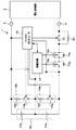
図45は、従来の電池パック100の一例の構成を示す。電池パック100は、二次電池(以下、単に電池と適宜称する)101、保護回路102、マイクロコンピュータ103、充電制御FET104、放電制御FET105、セルバランス回路106で構成されている。一例として、2つの電池101が直列に接続されている。電池パック100は、充電時には電圧供給部200に装着され、正極端子109および負極端子110がそれぞれ電圧供給部の正極端子および負極端子に接続され、充電が行われる。
FIG. 45 shows an exemplary configuration of a
保護回路102は、電池101の電圧をそれぞれ測定し、測定結果に基づき過充電状態や過放電状態の検出を行い、検出結果に基づき充電制御FET104および放電制御FET105を制御する。電池電圧が過充電検出電圧となったときは、充電制御FET104をOFFし、充電電流が流れないように制御する。電池電圧が過放電検出電圧となったときは、放電制御FET105がOFFされ、放電電流が流れない。
The
また、保護回路102は、測定した電池101の電圧をマイクロコンピュータ103に供給する。マイクロコンピュータ103は、供給された電池101の電圧によってセルバランスが崩れているか否かを判断する。セルバランスが崩れていると判断されると、電池101に対して並列に接続されたセルバランス回路106のスイッチ107のON/OFFが制御され、セル電圧が高い側の電池101が抵抗108を介して放電される。
The
このように、電池の電圧を測定し、測定結果に基づいて過充電状態を検出し、検出結果に応じて充放電制御FETを制御する技術が、下記の特許文献1に記載されている。
A technique for measuring the voltage of the battery, detecting the overcharge state based on the measurement result, and controlling the charge / discharge control FET according to the detection result is described in
一般に、リチウムイオン二次電池の電池を用いた電池パックにおいては、電池の電圧が4.2V(ボルト)となるように充電される。例えば、図45に示す例において、電圧供給部による充電電圧が8.4V±0.1Vの場合、電池101に印加される電圧の最大値が4.25Vとなる。実際には、セルバランス回路106による補正は、マイクロコンピュータ103の電圧測定精度のバラツキが存在し、電池101の電圧を完全に等しくするのが困難であった。したがって、充電電圧が8.4V±0.1Vの場合でも、一つの電池当たりで、最大4.25V以上の電圧が印加される可能性がある。したがって、各電池に印加される電圧が最大4.25Vの制御を行うことが困難であった。
Generally, in a battery pack using a lithium ion secondary battery, the battery is charged so that the voltage of the battery is 4.2 V (volts). For example, in the example shown in FIG. 45, when the charging voltage by the voltage supply unit is 8.4 V ± 0.1 V, the maximum value of the voltage applied to the
ところで、近い将来、電気用品安全法の改正が予定されている。この電気用品安全法の改正法では、電池の安全性をより十分に確保することを目的として、各電池に印加される充電電圧を4.25V以下とするように規定されている。今後は、各電池の電圧が4.25Vを超えることがないような対策を行う必要がある。 By the way, the revision of the Electrical Appliance and Material Safety Law is scheduled in the near future. In the revised law of the Electrical Appliance and Material Safety Law, the charging voltage applied to each battery is regulated to be 4.25 V or less for the purpose of ensuring sufficient battery safety. In the future, it is necessary to take measures to prevent the voltage of each battery from exceeding 4.25V.
対策の一つの方法として、電池に印加される電圧が4.25Vを超えないような充電電圧を発生する充電器を新たに設計することがある。しかしながら、既存の充電器を使用して充電を行う場合には、上述したように、電池に印加される電圧が4.25Vを超えてしまうので、既存の充電器を使用することができなくなる。 One method of countermeasure is to newly design a charger that generates a charging voltage such that the voltage applied to the battery does not exceed 4.25V. However, when charging is performed using an existing charger, as described above, the voltage applied to the battery exceeds 4.25 V, so that the existing charger cannot be used.
他の対策として、電池パック内の保護回路の精度を向上させ、過充電検出電圧が4.25V以下となるように設定することが考えられる。高精度のICを使用しても、4.24V±0.01Vの過充電保護の制御となる。この場合では、電池に印加される電圧が4.23Vとなると、過充電と判断される。そのため、正常な充電状態であるにもかかわらず、過充電保護がなされる問題がある。過充電保護によって充電制御FET104がOFFした場合、通常、充電異常としてアラームが発生する。このように、正常な充電状態にアラームが発生することは、好ましいことではない。 As another countermeasure, it is conceivable to improve the accuracy of the protection circuit in the battery pack and set the overcharge detection voltage to be 4.25 V or less. Even if a high-precision IC is used, the overcharge protection is controlled to 4.24V ± 0.01V. In this case, when the voltage applied to the battery is 4.23 V, it is determined that the battery is overcharged. For this reason, there is a problem that overcharge protection is performed even though the charging state is normal. When the charge control FET 104 is turned off by overcharge protection, an alarm is usually generated as a charging abnormality. Thus, it is not preferable that an alarm is generated in a normal charging state.
したがって、この発明の目的は、電池に印加される電圧が過充電検出電圧以下となるように充電を行うことができる電池パックおよび充電方法を提供することにある。 Accordingly, an object of the present invention is to provide a battery pack and a charging method that can perform charging so that the voltage applied to the battery is equal to or lower than the overcharge detection voltage.
上述した課題を解決するために、この発明は、1または互いに接続された複数の二次電池と、
外部の機器が接続される正極端子および負極端子と、
二次電池の正極と正極端子との間、または、二次電池の負極と負極端子との間に接続された抵抗値が変化する可変抵抗部と、
二次電池の電圧を測定する電池電圧測定部と、
電池電圧測定部の測定結果に基づき可変抵抗部の抵抗値を制御する制御部と
を有する電池パックである。
In order to solve the above-described problems, the present invention includes one or a plurality of secondary batteries connected to each other,
A positive terminal and a negative terminal to which external devices are connected;
A variable resistance unit that changes a resistance value connected between the positive electrode and the positive electrode terminal of the secondary battery or between the negative electrode and the negative electrode terminal of the secondary battery;
A battery voltage measuring unit for measuring the voltage of the secondary battery;
The battery pack includes a control unit that controls a resistance value of the variable resistance unit based on a measurement result of the battery voltage measurement unit.
この発明は、1または互いに接続された複数の二次電池と、
外部の機器が接続される正極端子および負極端子と、
二次電池の正極と正極端子との間、または、二次電池の負極と負極端子との間に接続された第1のスイッチと、
第1のスイッチに対して並列に接続された第1の抵抗部と、
二次電池の電圧を測定する電池電圧測定部と、
電池電圧測定部の測定結果に基づき第1のスイッチの開放状態および接続状態を制御する制御部と
を有する電池パックである。
The present invention includes one or a plurality of secondary batteries connected to each other,
A positive terminal and a negative terminal to which external devices are connected;
A first switch connected between the positive electrode and the positive electrode terminal of the secondary battery or between the negative electrode and the negative electrode terminal of the secondary battery;
A first resistor connected in parallel to the first switch;
A battery voltage measuring unit for measuring the voltage of the secondary battery;
The battery pack includes a control unit that controls an open state and a connection state of the first switch based on a measurement result of the battery voltage measurement unit.
この発明は、1または互いに接続された複数の二次電池と、
外部の機器が接続される正極端子および負極端子と、
二次電池の正極と正極端子との間、または、二次電池の負極と負極端子との間に接続された第1のスイッチと、
第1のスイッチに対して並列に接続された第1の抵抗部と、
二次電池の電圧を測定する電池電圧測定部と、
電池電圧測定部の測定結果に基づき第1のスイッチの開放状態および接続状態を制御する制御部と
を有し、
制御部は、
1または複数の二次電池のうち少なくとも1の電圧が予め設定された第1の充電上限電池電圧以上となる場合に、第1のスイッチを開放状態に切り替えて、正極端子および負極端子に接続された外部の電圧供給部から供給される充電電流を、第1の抵抗部を介して二次電池に流す電池パックである。
The present invention includes one or a plurality of secondary batteries connected to each other,
A positive terminal and a negative terminal to which external devices are connected;
A first switch connected between the positive electrode and the positive electrode terminal of the secondary battery or between the negative electrode and the negative electrode terminal of the secondary battery;
A first resistor connected in parallel to the first switch;
A battery voltage measuring unit for measuring the voltage of the secondary battery;
A control unit for controlling the open state and connection state of the first switch based on the measurement result of the battery voltage measurement unit,
The control unit
When at least one voltage of one or more secondary batteries is equal to or higher than a preset first charge upper limit battery voltage, the first switch is switched to an open state and connected to the positive terminal and the negative terminal. The battery pack allows a charging current supplied from an external voltage supply unit to flow to the secondary battery via the first resistance unit.
この発明は、1または互いに接続された複数の二次電池の電圧を測定し、
充電中に、二次電池の電圧が予め設定された第1の充電上限電池電圧以上となる場合に、二次電池に流れる充電電流の電流経路に設けられた第1のスイッチを開放状態に切り替えて、第1のスイッチに対して並列に接続された第1の抵抗部を介して充電電流を流す充電方法である。
The present invention measures the voltage of one or a plurality of secondary batteries connected to each other,
During charging, when the voltage of the secondary battery is equal to or higher than the preset first upper limit battery voltage, the first switch provided in the current path of the charging current flowing through the secondary battery is switched to the open state. In this charging method, the charging current is passed through the first resistor connected in parallel to the first switch.
上述したように、この発明では、1または互いに接続された複数の二次電池の電圧を測定し、測定結果に基づき可変抵抗部の抵抗値を制御するようにしているため、充電中における二次電池に対する印加電圧を低下させることができる。 As described above, in the present invention, the voltage of one or a plurality of secondary batteries connected to each other is measured, and the resistance value of the variable resistance unit is controlled based on the measurement result. The voltage applied to the battery can be reduced.
また、この発明では、1または互いに接続された複数の二次電池の電圧を測定し、充電中に、二次電池の電圧が予め設定された第1の充電上限電池電圧以上となった場合に、二次電池に流れる充電電流の電流経路に設けられた第1のスイッチをOFFして、第1のスイッチに対して並列に接続された第1の抵抗部を介して充電電流を流すようにしているため、充電中における二次電池に対する印加電圧を低下させることができる。 Further, in the present invention, when the voltage of one or a plurality of secondary batteries connected to each other is measured and the voltage of the secondary battery becomes equal to or higher than a preset first upper limit battery voltage during charging. The first switch provided in the current path of the charging current flowing through the secondary battery is turned off so that the charging current flows through the first resistor connected in parallel to the first switch. Therefore, the voltage applied to the secondary battery during charging can be reduced.
この発明は、二次電池に対する電流経路中に可変抵抗部を設け、二次電池の電圧の測定結果に基づき可変抵抗部の抵抗値を制御するようにしている。そのため、充電中における二次電池に対する印加電圧を低下させ、過充電検出電圧を超えないように充電を行うことができるという効果がある。 According to the present invention, a variable resistance portion is provided in the current path for the secondary battery, and the resistance value of the variable resistance portion is controlled based on the measurement result of the voltage of the secondary battery. Therefore, there is an effect that the voltage applied to the secondary battery during charging can be reduced and charging can be performed so as not to exceed the overcharge detection voltage.
また、この発明は、二次電池に対する電流経路中に、並列に接続された第1のスイッチおよび第1の抵抗部を設け、充電中に、二次電池の電圧が第1の充電上限電池電圧以上となった場合に、第1のスイッチをOFFして、充電電流を第1の抵抗部を介して流すようにしている。そのため、充電中における二次電池に対する印加電圧を低下させ、過充電検出電圧を超えないように充電を行うことができるという効果がある。 Further, according to the present invention, a first switch and a first resistor connected in parallel are provided in a current path to the secondary battery, and the voltage of the secondary battery is the first charging upper limit battery voltage during charging. In such a case, the first switch is turned off so that the charging current flows through the first resistance unit. Therefore, there is an effect that the voltage applied to the secondary battery during charging can be reduced and charging can be performed so as not to exceed the overcharge detection voltage.
以下、この発明の実施の形態について説明する。なお、説明は、以下の順序で行う。
<1.第1の実施形態(電流経路にスイッチおよび抵抗部を設けた例)>
<2.第2の実施形態(充電制御FETを強制的に制御する例)>
<3.第3の実施形態(温度センサを設けた例)>
<4.第4の実施形態(電流経路に可変抵抗部を設けた例)>
<5.第5の実施形態(外部電極端子間にスイッチおよび抵抗部を設けた例)>
なお、以下に説明する実施の形態は、この発明の好適な具体例であり、技術的に好ましい種々の限定が付されているが、この発明の範囲は、以下の説明において、特にこの発明を限定する旨の記載がない限り、これらの実施の形態に限定されないものとする。
Embodiments of the present invention will be described below. The description will be given in the following order.
<1. First Embodiment (Example in which a switch and a resistor are provided in a current path)>
<2. Second Embodiment (Example of Forcibly Controlling Charge Control FET)>
<3. Third Embodiment (Example in which a temperature sensor is provided)>
<4. Fourth Embodiment (example in which variable resistance portion is provided in current path)>
<5. Fifth Embodiment (Example in which a switch and a resistor are provided between external electrode terminals)>
The embodiments described below are preferred specific examples of the present invention, and various technically preferable limitations are given. However, the scope of the present invention is not limited to the present invention in the following description. Unless otherwise specified, the present invention is not limited to these embodiments.
<1.第1の実施形態>
この発明の第1の実施形態について説明する。この発明の第1の実施形態では、二次電池に対する充電電流の経路中に、並列に接続されたスイッチおよび抵抗部を設ける。そして、二次電池の電圧が予め設定された充電上限電池電圧を超えた場合にスイッチをOFFして、充電電流を抵抗部を介して流す。結果、二次電池に印加される充電電圧が低下し、二次電池の電圧が所定の電圧を超えない範囲で充電がなされる。
<1. First Embodiment>
A first embodiment of the present invention will be described. In the first embodiment of the present invention, a switch and a resistor connected in parallel are provided in the path of the charging current for the secondary battery. And when the voltage of a secondary battery exceeds the preset charge upper limit battery voltage, a switch is turned OFF and a charging current is sent through a resistance part. As a result, the charging voltage applied to the secondary battery decreases, and charging is performed in a range where the voltage of the secondary battery does not exceed a predetermined voltage.
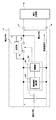
「電池パックの構成」
図1は、この発明の第1の実施形態による電池パック1の一例の構成を示す。電池パック1は、組電池10、保護回路12、マイクロコンピュータ13を有する。さらに、保護回路によって制御される充電制御FET(Field Effect Transistor)14aおよび放電制御FET15aを有する。セルバランス回路16a、16bおよびスイッチ19がマイクロコンピュータ13によって制御される。スイッチ19と並列に抵抗部20が接続される。スイッチ19は、FET,リレー等の構成とされる。
"Battery pack configuration"
FIG. 1 shows an exemplary configuration of a
組電池10は、直列接続された電池11aおよび11bからなる。電池11aおよび11bとしては、例えばリチウムイオン二次電池を用いることができる。リチウムイオン二次電池の場合、定電流充電と定電圧充電とを組合せたCC・CV(Constant Current Constant Voltage:定電流定電圧)充電方式でもって電池パックが充電される。充電開始時は、定電流で充電する定電流充電が行われ、電池電圧が所定の電圧に達した時に、定電流充電から2次電池を定電圧で充電する定電圧充電に切り替えられる。なお、以下の説明において、電池11aおよび11bを特に区別する必要がない場合には、単に電池11と適宜称する。
The assembled
保護回路12は、電池11の電圧(以下、セル電圧と適宜称する)を測定し、測定結果から過充電状態または過放電状態を検出し、検出結果によって、充電制御FET14aおよび放電制御FET15aを制御する。セル電圧が過充電検出電圧になると、充電制御FET14aがOFFし、充電電流が阻止される。充電制御FET14aのOFF後は、寄生ダイオード14bを介することによって放電のみが可能となる。セル電圧が過放電検出電圧になると、放電制御FET15aがOFFし、放電電流が阻止される。放電制御FET15aのOFF後は、寄生ダイオード15bを介することによって充電のみが可能となる。さらに、保護回路12は、測定した電池11のセル電圧をマイクロコンピュータ13に供給する。
The
マイクロコンピュータ13によってスイッチ19が制御される。スイッチ19は、電池11の充電電流の経路に挿入されている。放電時では、スイッチ19がONされる。マイクロコンピュータ13は、電池11のセル電圧が所定の電圧を超えた場合に、スイッチ19をONからOFFに切り替える。スイッチ19がOFFされると、スイッチ19に対して並列に接続された抵抗部20に充電電流が流れ、抵抗部20による電圧降下が発生する。この抵抗部20による電圧降下により、電池11に対する充電電圧が低下される。
The
セルバランス回路16aは、スイッチ17aおよび抵抗部18aの直列接続からなり、直列接続が電池11aに対して並列に接続されている。セルバランス回路16bは、スイッチ17bおよび抵抗部18bの直列接続からなり、直列接続が電池11bに対して並列に接続されている。マイクロコンピュータ13は、セルバランスが崩れているか否かを判断する。電池11aおよび11bの電圧が一致しない場合に、セルバランスが崩れていると判断される。
The
セルバランスが崩れていると判断すると、電池11aおよび11bに対して並列に接続されたセルバランス回路16aおよび16bを制御して、電池11aおよび11bのうち、セル電圧が高い側の電池11を放電される。例えば、電池11aのセル電圧が電池11bのセル電圧よりも高い場合には、スイッチ17aがONされ、電池11aが放電される。逆に、電池11bのセル電圧が電池11aのセル電圧よりも高い場合には、スイッチ17bがONされ、電池11bが放電される。なお、以下の説明において、スイッチ17aおよび17b、ならびに抵抗部18aおよび18bを特に区別する必要がない場合には、それぞれスイッチ17ならびに抵抗部18と適宜称する。
If it is determined that the cell balance is lost, the
さらに、マイクロコンピュータ13は、図示しないが、測定したセル電圧などの各種データを記憶する記憶部や、接続された本体機器と通信を行うための通信端子を備えている。
Further, although not shown, the
「充電制御方法」
第1の実施形態では、電池11のセル電圧に応じてスイッチ19が制御され、充電時の最大セル電圧が予め設定された所定の設定電圧、例えば4.25V(ボルト)を超えないように制御される。
"Charging control method"
In the first embodiment, the
スイッチ19の制御方法について説明する。図2は、スイッチ19の制御方法についての説明を容易とするため、図1に示す構成から、説明に必要な構成以外の部分を省略したものである。すなわち、図2に示す電池パック1では、図1に示すセルバランス回路16aおよび16b、充電制御FET14a、放電制御FET15aの図示を省略している。制御IC30は、図1に示す保護回路12およびマイクロコンピュータ13の機能を有するICであり、電池11のセル電圧を測定し、測定結果に基づいてスイッチ19を制御する。
A method for controlling the
ここで、電池11のセル電圧に関して所定の条件が成立した場合には、制御IC30の制御によってスイッチ19がOFFされ、充電電流ICが抵抗部20を介して流れる。抵抗部20に充電電流が流れることにより、この抵抗部20において電圧降下が発生し、この電圧降下によって電池11に印加される電圧が低下するため、充電時の最大セル電圧を設定電圧(例えば4.25V)以下に抑えることができる。抵抗部20の値は、下記のように設定される。
{(バラツキにより単一の電池にかかる最大電圧)−4.25V}/(充電終止電流)
ここで、充電終止電流は、充電器が充電完了を検出するために設定された充電電流の値である。
Here, when a predetermined condition is satisfied with respect to the cell voltage of the
{(Maximum voltage applied to a single battery due to variation) −4.25V} / (end-of-charge current)
Here, the charge end current is a value of a charge current set for the charger to detect the completion of the charge.
「スイッチ19の第1の制御方法」
スイッチ19の第1の制御方法について説明する。第1の制御方法では、充電中の電池11のセル電圧の上限を示す第1の充電上限電池電圧VBCAを予め設定する。制御IC30は、電池11aおよび11bのセル電圧VB1およびVB2と第1の充電上限電池電圧VBCAとを比較する。少なくとも一方のセル電圧が第1の充電上限電池電圧VBCA以上となると、スイッチ19がOFFされる。すなわち、制御IC30は、次の式(1)に示す条件が成立すると、スイッチ19をOFFする。
VB1≧VBCA または VB2≧VBCA ・・・(1)
“First Control Method of
A first control method of the
VB1 ≧ VBCA or VB2 ≧ VBCA (1)
スイッチ19がOFF状態では、充電電流ICが抵抗部20に流れ、抵抗部20において電圧降下VRAが発生する。抵抗部20で発生する電圧降下VRAは、抵抗部20の抵抗値をRAとすると、式(2)によって算出される。
VRA=RA×IC ・・・(2)
When the
VRA = RA × IC (2)
抵抗部20において発生する電圧降下により、電池11における最大セル電圧を設定電圧以下となるように制御することができる。例えば、設定電圧を4.25Vとした場合、第1の充電上限電池電圧VBCAを4.19Vとし、抵抗部20の抵抗値RAを0.8Ω(オーム)とすることにより、電池11における最大セル電圧を4.25V以下とすることができる。
The maximum cell voltage in the
例えば、充電電圧が4.24Vの電圧供給部2で充電した場合、スイッチ19がOFFされると、抵抗部20における電圧降下が40mVとなる。すなわち、電池11に対する充電電圧は、電圧供給部2の充電電圧4.24Vから40mVを減じた4.2Vとなる。これは、一般的なリチウムイオン二次電池における定格の充電電圧である。したがって、このように充電を制御することにより、電池11に対して適切な充電電圧で充電することができる。
For example, when charging is performed with the
第1の充電上限電池電圧VBCAは、過充電検出電圧よりも低い値に設定することによって、充電中に電池電圧が上昇して充電制御FET14aがOFFする前に、充電電圧を低下させ、充電が停止することを防止できる。なお、スイッチ19をOFFした後、電池11aおよび11bのセル電圧VB1およびVB2が共に第1の充電上限電池電圧VBCA未満となった場合に、スイッチ19をONさせることによって、充電状態に復帰する。
The first charge upper limit battery voltage VBCA is set to a value lower than the overcharge detection voltage, so that the battery voltage rises during charging and the
制御IC30は、図3に示すように、電圧比較器31aおよび31b、論理和演算器32を備える。電圧比較器31aは、電池11aのセル電圧VB1と第1の充電上限電池電圧VBCAとを比較し、比較結果に応じた値を論理和演算器32に出力する。例えば、セル電圧VB1が第1の充電上限電池電圧VBCA以上である場合には、値「1」を出力し、セル電圧VB1が第1の充電上限電池電圧VBCA未満である場合には、値「0」を出力する。
As shown in FIG. 3, the
電圧比較器31bは、電圧比較器31aと同様に、電池11bのセル電圧VB2と第1の充電上限電池電圧VBCAとを比較し、比較結果に応じた値を論理和演算器32に出力する。例えば、セル電圧VB2が第1の充電上限電池電圧VBCA以上である場合には、値「1」を出力し、セル電圧VB2が第1の充電上限電池電圧VBCA未満である場合には、値「0」を出力する。
Similarly to the
論理和演算器32は、電圧比較器31aおよび31bから供給された値の論理和出力をスイッチ19を制御するための制御信号として出力する。すなわち、電圧比較器31aおよび31bから供給された値の論理和を演算し、少なくとも何れか一方の値が「1」である場合に、スイッチ19をOFFするための制御信号を出力する。
The
[スイッチ19の第2の制御方法]
スイッチ19の第2の制御方法について説明する。第2の制御方法では、上述した第1の方法に加えて、さらに充電中であるか否かを制御IC30により判定する。充電中の場合に限り、スイッチ19のOFFを可能とする。すなわち、制御IC30は、式(3)に示す条件が成立した場合にスイッチ19をOFFし、この条件が成立しなかった場合にスイッチ19をONする。
「充電中」且つ(VB1≧VBCA または VB2≧VBCA) ・・・(3)
[Second Control Method of Switch 19]
A second control method of the
“Charging” and (VB1 ≧ VBCA or VB2 ≧ VBCA) (3)
スイッチ19がOFFになると、上述の第1の制御方法と同様に、式(2)に基づく電圧降下VRAが抵抗部20に発生するため、電池11における最大セル電圧を設定電圧以下となるように制御することができる。
When the
第2の制御方法は、スイッチ19をOFFした後、充電が終了するまでOFF状態を保持し、充電が終了した時点でスイッチ19をONする。このように、充電中であるか否かを判定することにより、放電時に抵抗部20が挿入されることによる電力消費を回避することができる。
In the second control method, after the
ここで、充電中であるか否かの判定方法について説明する。以下で説明する第1〜第7の判定方法のうち何れかを用いて充電中であるか否かを判定することができる。 Here, a method for determining whether or not charging is in progress will be described. Whether or not charging is in progress can be determined using any one of first to seventh determination methods described below.
「第1の判定方法」
第1の判定方法について説明する。第1の判定方法では、所定のサンプリング周期毎に組電池10の電圧(以下、電池電圧と適宜称する)VBTを測定する。そして、連続する2つの電池電圧VBTの差分値DVを算出し、差分値DVと予め設定された設定差分値SDVとを比較することにより、充電中であるか否かが判定される。
"First judgment method"
The first determination method will be described. In the first determination method, the voltage (hereinafter referred to as battery voltage) VBT of the assembled
図4に示すように、制御IC30は、サンプリング周期毎に電池電圧VBT1、VBT2、VBT3およびVBT4を測定し、記憶する。そして、電池電圧VBT1〜VBT4に基づいて、連続する電池電圧の差分値DV1、DV2およびDV3を算出する。差分値DV1〜DV3は、式(4)〜(6)によって算出される。
DV1=VBT2−VBT1 ・・・(4)
DV2=VBT3−VBT2 ・・・(5)
DV3=VBT4−VBT3 ・・・(6)
As shown in FIG. 4, the
DV1 = VBT2-VBT1 (4)
DV2 = VBT3-VBT2 (5)
DV3 = VBT4-VBT3 (6)
次に、制御IC30は、算出された差分値DV1〜DV3と予め設定された設定差分値SDVとを比較する。下記の式(7)に示す条件の中で、2つ以上の条件が成立する場合に充電中であると判断し、それ以外の場合に非充電中であると判断する。
DV1≧SDV,DV2≧SDV,DV3≧SDV ・・・(7)
Next, the
DV1 ≧ SDV, DV2 ≧ SDV, DV3 ≧ SDV (7)
このように、充電中であるか否かを判定することができる。例えば、サンプリング周期を10秒、設定差分値SDVを0.01Vとし、サンプリング周期毎に測定された電池電圧VBT1〜VBT4がそれぞれ8.00V、8.10V、7.95V、7.98Vである場合について考える。 In this way, it can be determined whether or not charging is in progress. For example, when the sampling period is 10 seconds, the set difference value SDV is 0.01V, and the battery voltages VBT1 to VBT4 measured at each sampling period are 8.00V, 8.10V, 7.95V, and 7.98V, respectively. think about.
この場合、式(4)〜(6)に基づいて算出される差分値DV1〜DV3は、それぞれ0.1V、−0.15V、0.03Vとなる。したがって、DV1およびDV3が設定差分値SDV以上となるため、充電状態が検出される。 In this case, the difference values DV1 to DV3 calculated based on the equations (4) to (6) are 0.1V, −0.15V, and 0.03V, respectively. Therefore, since DV1 and DV3 are equal to or greater than the set difference value SDV, the state of charge is detected.
一方、電池パック1に対して充電器や本体機器が接続されていない無負荷時には、図5に示すように、充電電流および放電電流の何れも流れていないため、電池電圧VBT1'〜VBT4'が変化しない。そのため、上述した式(4)〜(6)に基づいて算出される電池電圧VBT1'〜VBT4'の差分値DV1'〜DV3'は、それぞれ略0Vとなる。したがって、上述した式(7)の条件が成立しないので、非充電中と判断することができる。
On the other hand, at the time of no load when the charger or the main device is not connected to the
なお、電池電圧を測定する回数は、4回程度とすると好ましい。電池電圧の測定回数を2回と設定した場合を考える。最初の電圧測定と次の電圧測定との間でスイッチ19がOFFすると、抵抗部20における電圧降下により、電池11に対する充電電圧および充電電流が低下し、電池電圧VBTが低下する。その結果、上述した判定を行うと、差分値DVが設定差分値SDV未満となり、充電中にも関わらず非充電中と判定されてしまう問題が生じる。
In addition, it is preferable when the frequency | count which measures a battery voltage shall be about 4 times. Consider a case where the number of battery voltage measurements is set to two. When the
「第2の判定方法」
第2の判定方法について説明する。第2の判定方法では、抵抗部20の両端の電圧によって、充電中であるか否かが判定される。制御IC30は、抵抗部20の両端の電圧を測定し、測定された電圧が、充電方向の電圧値として予め設定された所定値以上である場合に、充電中であると判定する。
"Second determination method"
A second determination method will be described. In the second determination method, whether or not charging is in progress is determined based on the voltage across the
「第3の判定方法」
第3の判定方法について説明する。第3の判定方法では、組電池10の電池電圧VBTと、電圧供給部2に接続される正極端子3および負極端子4の間の電圧(以下、端子電圧と適宜称する)VBEとに基づいて充電中であるか否かを判定する。
"Third determination method"
A third determination method will be described. In the third determination method, charging is performed based on the battery voltage VBT of the assembled
充電中においては、電圧供給部2から供給される充電電圧VBEよりも、組電池10の電池電圧VBTの方が低いと考えられる。したがって、電池電圧VBTおよび端子電圧VBEを比較することにより、充電中であるか否かが判定できる。
During charging, the battery voltage VBT of the assembled
制御IC30は、電池11のセル電圧に基づいて組電池10の電池電圧VBTを算出する。また、制御IC30は、電池パック1の正極端子3および負極端子4の電圧に基づいて端子電圧VBEを算出する。電池電圧VBTおよび端子電圧VBEを比較し、式(8)に示す条件が成立した場合に充電中であると判定し、この条件が成立しなかった場合に非充電中であると判定する。
電池電圧VBT<端子電圧VBE ・・・(8)
The
Battery voltage VBT <terminal voltage VBE (8)
「第4の判定方法」
第4の判定方法について説明する。図6に示すように、電池パック1には、充電対象の電池パックが正規のものであるか否かを判定するために、認識用端子5が設けられ、認識用端子5と負極端子4との間に認識用抵抗7が接続される。電池パック1に対して電圧供給部2が接続されると、認識用抵抗7に対して所定の電流が流れる。認識用抵抗7に流れる電流や、認識用抵抗7で発生する電圧降下に基づいて、充電中であるか否かを判定する。例えば、認識用抵抗7に電圧降下が発生した場合には、充電中であると判定する。
"Fourth determination method"
A fourth determination method will be described. As shown in FIG. 6, the
「第5の判定方法」
第5の判定方法について説明する。図7に示すように、電池パック1には、例えば通信用端子6が設けられ、マイクロコンピュータ13に接続されている。マイクロコンピュータ13は、電池パック1に本体機器111'のマイクロコンピュータと通信を行う。電池パック1に設けられた通信端子6を用いて、本体機器111'と通信を行っているか否かに基づいて、充電中であるか否かを判断する。例えば、マイクロコンピュータ13が通信端子6を介して本体機器111'と通信を行っている場合は、放電中であると判定される。一方、マイクロコンピュータ13が本体機器111'と通信を行っていない場合は、充電中であると判定される。
"Fifth determination method"
A fifth determination method will be described. As shown in FIG. 7, the
「第6の判定方法」
第6の判定方法について説明する。第6の判定方法では、充電電流が測定され、測定結果に基づいて充電中であるか否かが判定される。図8に示すように、電流経路中に電流検出部21を設ける。電流検出部21は、電流経路を流れる電流の大きさおよび向きを測定し、測定結果を制御IC30に供給する。制御IC30は、測定結果に基づいて、電流が充電方向に流れている場合に充電中であると判定する。一方、放電方向に流れている場合や電流が流れていない場合には、非充電中であると判定する。
"Sixth judgment method"
A sixth determination method will be described. In the sixth determination method, the charging current is measured, and it is determined whether charging is in progress based on the measurement result. As shown in FIG. 8, a
電流検出部21は、例えば予め設定されたサンプリング周期毎に所定回数だけ電流を測定し、測定された所定回数分の電流値に基づいて平均電流値を算出して判定に用いるようにしてもよい。第6の判定方法では、充電電流を直接測定するため、電池電圧に基づく判定方法と比較して、充電中であるか否かをより確実に判定することができる。
For example, the
「第7の判定方法」
第7の判定方法について説明する。第7の判定方法では、電流経路に設けられた電流検出抵抗の電圧が測定され、測定結果に基づいて充電中であるか否かが判定される。図9に示すように、電流検出部21は、電流検出抵抗22および電流検出器23を備える。電流検出器23は、電流検出抵抗22の両端の電圧VRBを測定し、測定結果を制御IC30に供給する。
"Seventh determination method"
A seventh determination method will be described. In the seventh determination method, the voltage of the current detection resistor provided in the current path is measured, and it is determined whether charging is in progress based on the measurement result. As shown in FIG. 9, the
制御IC30は、供給された電圧VRBと予め設定された充電判定電圧とを比較し、電圧VRBが充電判定電圧以上である場合に、充電中であると判定する。すなわち、制御IC30は、式(9)に示す条件が成立した場合に充電中であると判定し、この条件が成立しなかった場合に非充電中であると判定する。
電圧VRB≧充電判定電圧 ・・・(9)
The
Voltage VRB ≧ charge determination voltage (9)
電流検出器23は、予め設定されたサンプリング周期毎に所定回数だけ電流検出抵抗22の電圧を測定し、測定された所定回数分の電圧値に基づいて平均電圧値を算出して判定に用いるようにしてもよい。
The
「セルバランスの制御方法」
セルバランスの制御方法について、図10を参照して説明する。この発明の第1の実施形態では、電池11aおよび11bのセル電圧VB1およびVB2が略等しくなるように各電池電圧を制御する。
"Cell balance control method"
A cell balance control method will be described with reference to FIG. In the first embodiment of the present invention, each battery voltage is controlled so that the cell voltages VB1 and VB2 of the
なお、図10は、セルバランスの制御方法を説明するのに必要な構成の部分のみを示す。すなわち、図10に示す電池パック1では、充電制御FET14a、放電制御FET15aの図示が省略されている。制御IC30は、保護回路12およびマイクロコンピュータ13の機能を有する。
FIG. 10 shows only a part of the configuration necessary to explain the cell balance control method. That is, in the
電池11aおよび11bに対してセルバランス回路16aおよび16bがそれぞれ並列に接続されている。セルバランス回路16aおよび16bに設けられたスイッチ17aおよび17bがOFF状態では、セルバランス回路16aおよび16bには、電流が流れない。電池11aおよび11bのセル電圧に関して所定の条件が成立した場合には、制御IC30によってスイッチ17aおよび17bがONされる。
セルバランス回路16aに設けられたスイッチ17aがONすると、電池11aの放電電流が抵抗部18aに流れ、電池11aのセル電圧が低下する。充電中では、電圧供給部2からの充電電流の一部が抵抗部18aに流れ、電池11aの電圧上昇が抑えられる。同様に、セルバランス回路16bに設けられたスイッチ17bがONされると、電池11bの放電電流が抵抗部18bに流れ、電池11bのセル電圧が低下する。充電では、電圧供給部2からの充電電流の一部が抵抗部18bに流れ、電池11bの電圧上昇が抑えちれる。
When the
スイッチ17aおよび17bの制御方法としては、以下に述べる第1〜第3の制御方法を用いることができる。
As a control method of the
「スイッチ17aおよび17bの第1の制御方法」
第1の制御方法は、セルバランスを制御する際に用いる第2の充電上限電池電圧VBCBおよび上限電池電圧差VBDLを予め設定する。制御IC30は、充電中であり、且つ、電池11aのセル電圧VB1が第2の充電上限電池電圧VBCB以上である場合に、スイッチ17aをONする。制御IC30は、充電中であり、且つ、電池11aおよび11bのセル電圧VB1およびVB2の差分(VB1−VB2)が上限電池電圧差VBDL以上である場合においても、スイッチ17aをONする。
“First Control Method of
In the first control method, the second charging upper limit battery voltage VBCB and the upper limit battery voltage difference VBDL used when controlling the cell balance are set in advance. The
すなわち、制御IC30は、式(10)に示す条件が成立する場合にスイッチ17aをONし、この条件が成立しない場合にスイッチ17aをOFFする。
「充電中」且つ(VB1≧VBCBまたはVB1−VB2≧VBDL)・・・(10)
That is, the
“Charging” and (VB1 ≧ VBCB or VB1-VB2 ≧ VBDL) (10)
上述と同様に、制御IC30がスイッチ17bを制御する。すなわち、制御IC30は、式(11)に示す条件が成立する場合にスイッチ17bをONし、この条件が成立しない場合にスイッチ17bをOFFする。
「充電中」且つ(VB2≧VBCBまたはVB2−VB1≧VBDL)・・・(11)
As described above, the
“Charging” and (VB2 ≧ VBCB or VB2-VB1 ≧ VBDL) (11)
ここで、第2の充電上限電池電圧VBCBは、上述した第1の充電上限電池電圧VBCAとは別の設定値として用意する。第2の充電上限電池電圧VBCBは、第1の充電上限電池電圧VBCAと同一、または第1の充電上限電池電圧よりも低い値とすると好ましい。 Here, the second charging upper limit battery voltage VBCB is prepared as a set value different from the first charging upper limit battery voltage VBCA described above. Second charging upper limit battery voltage VBCB is preferably the same as first charging upper limit battery voltage VBCA or a value lower than the first charging upper limit battery voltage.
第2の充電上限電池電圧VBCBは、過充電検出電圧よりも低い値に設定すると好ましい。こうすることにより、充電中に過充電を検出して充電制御FET14aがOFFする前に、セルバランス回路16aおよび16bによる放電によってセル電圧を低下させ、充電が停止することを防止することができるからである。
Second charging upper limit battery voltage VBCB is preferably set to a value lower than the overcharge detection voltage. By doing so, it is possible to prevent the charging from being stopped by reducing the cell voltage due to the discharge by the
上述したスイッチ17aおよび17bの第1の制御方法では、所定の制御周期時間毎にセル電圧VB1およびVB2の測定、ならびにスイッチ17aおよび17bを制御するようにしている。第1の制御方法に基づいてスイッチ17aおよび17bをONした後は、抵抗部18aおよび18bに放電電流が流れることにより、セル電圧VB1およびVB2が直ちに低下する。
In the first control method of the
このとき、スイッチ17aおよび17bをONした後、制御周期時間経過後に第1の制御方法に示す処理を行うと、セル電圧の低下により式(10)および(11)に示す条件が不成立となるため、スイッチ17aおよび17bを再度OFFすることになる。スイッチ17aおよび17bを再度OFFした場合には、セル電圧が十分に低下していないため、すぐにセル電圧VB1およびVB2が上昇し、次の制御周期時間経過後に式(10)および(11)に示す条件が成立してしまう。すなわち、制御周期時間毎にスイッチ17aおよび17bを制御すると、スイッチ17aおよび17bのON/OFF動作を制御周期時間毎に繰り返してしまう。
At this time, if the processing shown in the first control method is performed after the control cycle time has elapsed after the
そこで、第1の制御方法では、スイッチ17aおよび17bの状態を保持する保持時間を予め設定し、スイッチ17aおよび/または17bがONされた場合には、設定された保持時間の間、スイッチ17aおよび17bの状態を保持すると好ましい。具体的には、例えば制御周期時間を10秒程度に設定した場合、保持時間を60秒程度とする。
Therefore, in the first control method, a holding time for holding the states of the
「スイッチ17aおよび17bの第2の制御方法」
第2の制御方法では、充電中であり、且つ、電池11aおよび11bのセル電圧VB1およびVB2の差分(VB1−VB2)が上限電池電圧差VBDL以上である場合に、スイッチ17aをONする。すなわち、制御IC30は、式(12)に示す条件が成立する場合にスイッチ17aをONし、この条件が成立しない場合にスイッチ17aをOFFする。
「充電中」且つVB1−VB2≧VBDL ・・・(12)
“Second Control Method of
In the second control method, the
“Charging” and VB1-VB2 ≧ VBDL (12)
上述と同様に、制御IC30は、式(13)に示す条件が成立する場合にスイッチ17bをONし、この条件が成立しない場合にスイッチ17bをOFFする。
「充電中」 且つ VB2−VB1≧VBDL ・・・(13)
Similarly to the above, the
“Charging” and VB2-VB1 ≧ VBDL (13)
なお、この第2の制御方法は、上述した第1の制御方法と同様に、所定の制御周期時間毎にスイッチ17aおよび17bの制御を行い、スイッチ17aおよび17bをONした後は、保持時間の間、ON状態を保持する。
In the second control method, similarly to the first control method described above, the
「スイッチ17aおよび17bの第3の制御方法」
第3の制御方法では、充電中であり、且つ、電池11aのセル電圧VB1が第2の充電上限電池電圧VBCB以上である場合に、スイッチ17aをONする。すなわち、制御IC30は、式(14)に示す条件が成立する場合にスイッチ17aをONし、この条件が成立しない場合にスイッチ17aをOFFする。
「充電中」且つVB1≧VBCB ・・・(14)
“Third Control Method of
In the third control method, the
“Charging” and VB1 ≧ VBCB (14)
上述と同様に、充電中であり、且つ、電池11bのセル電圧VB2が第2の充電上限電池電圧VBCB以上である場合に、スイッチ17bをONする。すなわち、制御IC30は、式(15)に示す条件が成立する場合にスイッチ17bをONし、この条件が成立しない場合にスイッチ17bをOFFする。
「充電中」且つVB2≧VBCB ・・・(15)
Similarly to the above, when the battery is being charged and the cell voltage VB2 of the
“Charging” and VB2 ≧ VBCB (15)
上述した第1および第2の制御方法と同様に、所定の制御周期時間毎にスイッチ17aおよび17bの制御を行い、スイッチ17aおよび17bをONした後は、保持時間の間、ON状態を保持する。
Similar to the first and second control methods described above, the
「抵抗部20および18の構成例」
抵抗部20および18として適用可能な素子について説明する。図11Aは、抵抗部20および18を、1つの抵抗素子35で構成する場合を示す。抵抗素子35としては、固定抵抗器や正特性サーミスタ、ポジスタ、PTC(Positive Temperature Coefficient)、ヒューズ抵抗器等を用いることができる。固定抵抗器は、温度による抵抗値の変化が小さい素子である。正特性サーミスタは、温度が高くなるに従って、抵抗値が増大する素子である。正特性サーミスタは、抵抗値によってポジスタやPTCに分類される。
“Configuration Example of
An element applicable as the
ポジスタは、正特性サーミスタの一種であり、後述するPTCと比較して抵抗値が大きく、約10Ω以上が主流の素子である。ポジスタは、一般的に所定の温度領域において抵抗値が急激に増大する。ポジスタを抵抗素子35として使用した場合、抵抗素子35に過大電圧が印加され、過大電流が流れて温度が高温となった場合に、抵抗値が急激に増大して流れる電流が小さくなる。
The posistor is a kind of positive-characteristic thermistor, and has a resistance value larger than that of a PTC described later, and a mainstream element of about 10Ω or more. In general, the resistance value of the posistor increases rapidly in a predetermined temperature range. When a posistor is used as the
PTCは、正特性サーミスタの一種であり、ポジスタと比較して抵抗値が小さく、約1Ω以下が主流の素子である。PTCは、ポジスタと同様に、一般的に所定の温度領域において抵抗値が急激に増大する。例えば、PTCを抵抗素子35として使用した場合、抵抗素子35に過大電圧が印加され、過大電流が流れて温度が高温となった場合に、抵抗値が急激に増大して流れる電流が小さくなる。
PTC is a kind of positive temperature coefficient thermistor, and has a resistance value smaller than that of a posistor, and a mainstream element of about 1Ω or less. The resistance value of the PTC generally increases rapidly in a predetermined temperature range, like the posistor. For example, when PTC is used as the
ヒューズ抵抗器は、過大電圧が印加され、過大電流が流れて温度が高温となった場合に、素子の電流経路が溶断して電流を遮断することができる。 When an excessive voltage is applied to the fuse resistor and an excessive current flows and the temperature becomes high, the current path of the element is blown to interrupt the current.
抵抗部20としては、例えば図11Bに示すように、抵抗素子35および温度スイッチ素子36を直列に接続したものを使用できる。温度スイッチ素子36としては、例えば、サーモスタットや温度ヒューズを用いることができる。
As the
サーモスタットは、素子の温度が予め設定された温度よりも高くなった場合に、スイッチをOFFして電流を遮断する。また、素子の温度が設定温度よりも低くなった場合に、スイッチをONする。一般的に、スイッチをOFFする際の設定温度(遮断温度)と、スイッチをONする際の設定温度(復帰温度)とが異なり、遮断温度が復帰温度よりも高く、その温度差が1℃〜20℃程度となるように設定されている。 The thermostat cuts off the current by turning off the switch when the temperature of the element becomes higher than a preset temperature. Also, when the temperature of the element becomes lower than the set temperature, the switch is turned on. Generally, the set temperature (switching temperature) when the switch is turned off is different from the set temperature (return temperature) when the switch is turned on, and the cut-off temperature is higher than the return temperature, and the temperature difference is 1 ° C to It is set to be about 20 ° C.
温度ヒューズは、素子の温度が高温となった場合に、ヒューズのエレメントを溶断することによって流れる電流を遮断する。ヒューズエレメントを遮断した場合には、再度電流を流すことができない。温度ヒューズに用いられるヒューズエレメントは、一般的に、融点が100℃〜200℃程度の低融点金属が用いられる。 The thermal fuse cuts off the flowing current by fusing the element of the fuse when the temperature of the element becomes high. When the fuse element is cut off, no current can flow again. Generally, a low melting point metal having a melting point of about 100 ° C. to 200 ° C. is used for a fuse element used for a thermal fuse.
図12は、抵抗部20における温度および抵抗値の関係の一例を示す。抵抗部20に用いられる抵抗素子35としては、通常、抵抗値が10mΩ〜90Ω程度のものが用いられ、より好適には、抵抗値が100mΩ〜5Ω程度のものが用いられる。この例では、抵抗部20に用いられる抵抗素子35として、周囲の温度が23℃の場合に抵抗値が約0.8Ωとなるような固定抵抗器、サーミスタおよびポジスタを用いた場合の特性を示している。
FIG. 12 shows an example of the relationship between the temperature and the resistance value in the
図12に示すように、固定抵抗器は、温度による抵抗値の変動が少なく、抵抗値が常に略0.8Ω程度である。サーミスタは、温度が上昇するに従って抵抗値が増大する。ポジスタは、温度が上昇するに従って抵抗値が増大するが、特に、温度が100℃程度になった場合に、抵抗値が急激に増大する。 As shown in FIG. 12, the fixed resistor has little variation in resistance value due to temperature, and the resistance value is always about 0.8Ω. The thermistor increases in resistance as the temperature increases. The resistance value of the posistor increases as the temperature rises. In particular, when the temperature reaches about 100 ° C., the resistance value increases rapidly.
ここで、例えば、充電上限電圧が4.25Vである2つの電池11が直列接続され、抵抗値が90mΩの固定抵抗器からなる抵抗部20を用いた電池パック1を充電した場合について考える。この電池パック1に対して、充電電圧が8.4Vであり、充電電流値が100mAである電圧供給部2を接続して充電を行った場合、抵抗部20の電圧は、9mVとなる。
Here, for example, a case is considered where two
このとき、例えば一方の電池11のセル電圧が4.10Vであるとすると、他方の電池11のセル電圧は、4.291Vとなり、充電上限電圧である4.25Vを超えてしまうことになる。
At this time, for example, if the cell voltage of one
このように、抵抗部20の抵抗値が小さい場合には、抵抗部20による電圧降下が小さく、電池11のセル電圧を十分に低下させることができない。
Thus, when the resistance value of the
例えば、抵抗値が100Ωの固定抵抗器からなる抵抗部20と、抵抗値が0.02Ωのスイッチ19とを用いた電池パック1を充電した場合について考える。この場合において、スイッチ19がOFFされたときの抵抗部20の電圧が0.02Vであるとすると、抵抗部20に流れる電流は、0.2mAとなる。一方、スイッチ19がONされたときのスイッチ19の電圧が0.02Vであるとすると、スイッチ19に流れる電流は、1Aとなる。
For example, consider a case where the
したがって、スイッチ19がOFFされた場合には、スイッチ19がONされた場合と比較して、流れる電流が減少してしまうため、充電時間が約2倍以上長くなってしまう。
Therefore, when the
例えば、抵抗部20としてポジスタを用いた場合について考える。抵抗部20としてポジスタを用いた場合、図12に示すように、温度が23℃のときに抵抗値が約0.8Ωである。スイッチ19がOFFされたときの抵抗部20の電圧が0.1Vであるとすると、抵抗部20に流れる電流は、約125mAとなる。
For example, consider a case where a posistor is used as the
そして、抵抗部20に流れる電流によって温度が90℃となると、抵抗部20の抵抗値が約2Ωとなる。そのため、抵抗部18に流れる電流が約50mAに減少する。
When the temperature is 90 ° C. due to the current flowing through the
このように、抵抗部20としてポジスタを用いた場合には、高温時に抵抗値が増大するため、抵抗部20に流れる電流量を抑え、温度の上昇を防ぐことができる。
As described above, when a posistor is used as the
抵抗部20に用いる抵抗素子35としては、電池パック1の使用条件や電池11の特性に応じて決定するとよい。例えば、電池11の電池容量や、最大充電電流値、充電終了条件の充電電流値を考慮して、抵抗部20に用いる抵抗素子35を決定するとより好ましい。
The
図13は、抵抗部18における温度および抵抗値の関係の一例を示す。抵抗部18に用いられる抵抗素子35としては、通常、抵抗値が1Ω〜9kΩ程度のものが用いられ、より好適には、抵抗値が10Ω〜1kΩ程度のものが用いられる。この例では、抵抗部18に用いられる抵抗素子35として、周囲の温度が23℃の場合に抵抗値が約120Ωとなるような固定抵抗器、サーミスタおよびポジスタを用いた場合の特性を示している。
FIG. 13 shows an example of the relationship between temperature and resistance value in the resistance section 18. As the
図13に示すように、固定抵抗器は、温度による抵抗値の変動が少なく、抵抗値が常に略120Ω程度である。サーミスタは、温度が上昇するに従って抵抗値が増大する。ポジスタは、温度が上昇するに従って抵抗値が増大するが、特に、温度が100℃程度になった場合に、抵抗値が急激に増大する。 As shown in FIG. 13, the fixed resistor has a small variation in resistance value due to temperature, and the resistance value is always about 120Ω. The thermistor increases in resistance as the temperature increases. The resistance value of the posistor increases as the temperature rises. In particular, when the temperature reaches about 100 ° C., the resistance value increases rapidly.
ここで、例えば、定格放電容量が1500mAhであり、電池電圧が4.25Vである電池11と、抵抗値が10kΩの固定抵抗器からなる抵抗部18とを用いた電池パック1を充電した場合について考える。この場合において、スイッチ17がONされると、抵抗部18に流れる電流は、0.425mAとなるため、この状態を1時間続行した場合の抵抗部18による放電電流容量は、0.425mAhとなる。この抵抗部18による放電電流容量は、電池11の定格放電容量に対して、約0.03%程度であるため、セル電圧を十分に調整することができない。
Here, for example, when the
この場合の抵抗部18による発熱量は、約1.8mWであり、発熱量を小さくすることができる。そのため、抵抗部18の発熱による温度上昇量を小さくすることができる。 In this case, the amount of heat generated by the resistance portion 18 is about 1.8 mW, and the amount of heat generated can be reduced. Therefore, the amount of temperature increase due to the heat generation of the resistance portion 18 can be reduced.
このように、抵抗部18の抵抗値が大きい場合には、温度上昇量を小さくすることができるが、セル電圧を十分に調整することができない。 As described above, when the resistance value of the resistance portion 18 is large, the temperature rise amount can be reduced, but the cell voltage cannot be adjusted sufficiently.
例えば、定格放電容量が1500mAhであり、電池電圧が4.25Vである電池11と、抵抗値が9Ωの固定抵抗器からなる抵抗部18とを用いた電池パック1を充電した場合について考える。この場合において、スイッチ17がONされると、抵抗部18に流れる電流は、約472mAとなるため、この状態を1時間続行した場合の抵抗部18による放電電流容量は、472mAhとなる。この抵抗部18による放電電流容量は、電池11の定格放電容量に対して、約31%程度であるため、セル電圧を十分に調整することができる。
For example, consider a case where the
一方、この場合の抵抗部18による発熱量は、約2Wであり、発熱量が大きくなってしまう。そのため、抵抗部18の発熱による温度上昇量が大きくなってしまう。 On the other hand, the amount of heat generated by the resistance portion 18 in this case is about 2 W, and the amount of heat generated becomes large. For this reason, the amount of temperature increase due to the heat generated by the resistor 18 increases.
このように、抵抗部18の抵抗値が小さい場合には、セル電圧を十分に調整することができるが、温度上昇量が大きくなってしまう。 As described above, when the resistance value of the resistance portion 18 is small, the cell voltage can be sufficiently adjusted, but the temperature increase amount becomes large.
そこで、温度上昇量を抑える場合には、抵抗部18として、例えばポジスタを用いる。抵抗部18としてポジスタを用いた場合、図13に示すように、温度が23℃のときに抵抗値が約120Ωである。スイッチ17がONされ、例えば抵抗部18に4.2Vの電圧が印加されると、抵抗部18に流れる電流は、約35mAとなり、抵抗部18による発熱量は、約147mWとなる。
Therefore, in order to suppress the temperature rise amount, for example, a posistor is used as the resistance unit 18. When a posistor is used as the resistance portion 18, as shown in FIG. 13, the resistance value is about 120Ω when the temperature is 23 ° C. When the
そして、抵抗部18に流れる電流によって温度が90℃となると、抵抗部18の抵抗値が200Ωとなる。そのため、抵抗部18に流れる電流が約21mAに減少し、抵抗部18による発熱量が約88.2mWとなる。 When the temperature reaches 90 ° C. due to the current flowing through the resistor 18, the resistance value of the resistor 18 becomes 200Ω. Therefore, the current flowing through the resistance portion 18 is reduced to about 21 mA, and the amount of heat generated by the resistance portion 18 is about 88.2 mW.
このように、抵抗部18としてポジスタを用いた場合には、高温時に抵抗値が増大するため、温度の上昇による発熱量の増大を抑え、温度の上昇を防ぐことができる。 As described above, when a posistor is used as the resistance portion 18, the resistance value increases at a high temperature. Therefore, an increase in the amount of heat generated due to a temperature rise can be suppressed, and a temperature rise can be prevented.
抵抗部18に用いる抵抗素子35としては、電池パック1の使用条件や電池11の特性に応じて決定するとよい。例えば、電池11の電池容量や、最大充電電流値、充電終了条件を考慮して、抵抗部20に用いる抵抗素子35を決定するとより好ましい。また、電池11の定格放電容量が大きい場合には、抵抗部18の抵抗値を小さい値に設定し、電池11の定格放電容量が小さい場合には、抵抗部18の抵抗値を大きい値に設定するとよい。
The
「充電制御処理」
次に、この発明の第1の実施形態による電池パック1の充電制御処理の流れについて、図14〜図16に示すフローチャートを参照して説明する。なお、特別な記載がない限り、以下の処理は、マイクロコンピュータ13の制御の下で行われるものとする。
"Charge control process"
Next, the flow of the charging control process for the
この発明の第1の実施形態では、スイッチ19およびスイッチ17を制御して、電池11aおよび11bに対する充電を制御している。図14に示すように、電池パック1に対する充電制御処理では、スイッチ19の制御(ステップS1)およびスイッチ17の制御(ステップS2)が並行して行われる。以下では、ステップS1およびS2で行われる各スイッチの制御処理について、ステップ毎に説明する。
In the first embodiment of the present invention, the charging of the
先ず、ステップS1に示すスイッチ19の制御処理の流れについて、図15を参照して説明する。ここでは、上述したスイッチ19の第2の制御方法について説明する。ステップS11では、予め設定された制御周期時間だけ待機し、制御周期時間に達した時点でステップS12以降の処理に移行する。
First, the flow of control processing of the
ステップS12では、充電中であるか否かが判定される。充電中であるか否かの判定は、上述した第1〜第7の判定方法のうち、何れかの方法を用いることによって行われる。充電中であると判定されると、処理がステップS13に移行する。一方、非充電中であると判定されると、ステップS17において、スイッチ19がONされる。
In step S12, it is determined whether charging is in progress. The determination as to whether or not the battery is being charged is performed by using any one of the first to seventh determination methods described above. If it is determined that charging is in progress, the process proceeds to step S13. On the other hand, if it is determined that the battery is not being charged, the
ステップS13において、電池11aおよび11bのセル電圧VB1およびVB2と第1の充電上限電池電圧VBCAとが比較される。比較の結果、セル電圧VB1が第1の充電上限電池電圧VBCA以上である場合、またはセル電圧VB2が第1の充電上限電池電圧VBCA以上である場合には、ステップS14において、スイッチ19がOFFされる。
In step S13, cell voltages VB1 and VB2 of
次のステップS15では、充電中であるか否かが判定される。充電中であると判定されると、処理がステップS15に戻り、充電中であるか否かが再度判定される。非充電中であると判定されると、ステップS16において、スイッチ19がONされる。そして、処理がステップS11に戻る。
In the next step S15, it is determined whether or not charging is in progress. If it is determined that charging is in progress, the process returns to step S15, and it is determined again whether charging is in progress. If it is determined that the battery is not being charged, the
一方、ステップS13に示す条件が成立しないと、ステップS17において、スイッチ19がONされる。
On the other hand, if the condition shown in step S13 is not satisfied, the
次に、ステップS2に示すスイッチ17の制御処理の流れについて、図16を参照して説明する。ここでは、上述したスイッチ17aおよび17bの第1の制御方法が用いられる。ステップS21では、予め設定された制御周期時間だけ待機し、制御周期時間に達した時点でステップS22以降の処理に移行する。
Next, the flow of the control process of the
ステップS22では、スイッチ17aおよび17bがOFFされ、ステップS23において、充電中であるか否かが判定される。充電中であるか否かの判定は、上述した第1〜第7の判定方法のうち、何れかの方法を用いることによって行われる。充電中であると判定されると、処理がステップS24に移行する。一方、非充電中であると判定されると、処理がステップS21に戻り、制御周期時間だけ待機する。
In step S22, the
ステップS24では、電池11aおよび11bのセル電圧VB1およびVB2と第2の充電上限電池電圧とが比較される。比較の結果、セル電圧VB1が第2の充電上限電池電圧VBCB以上であり、且つ、セル電圧VB2が第2の充電上限電池電圧VBCB以上である場合には、処理がステップS25に移行する。
In step S24, cell voltages VB1 and VB2 of
ステップS25では、スイッチ17aおよび17bがONされ、セルバランス回路16aおよび16bにより電池11aおよび11bの放電処理が行われる。そして、次のステップS26において、スイッチ17aおよび17bのON状態が予め設定された保持時間だけ保持され、保持時間経過後に処理がステップS21に戻る。
In step S25, the
一方、ステップS24に示す条件が成立しないと、処理がステップS27に移行する。ステップS27では、電池11aのセル電圧VB1と第2の充電上限電池電圧VBCBとが比較される。また、セル電圧VB1およびVB2の差分(VB1−VB2)と上限電池電圧差VBDLとが比較される。比較の結果、セル電圧VB1が第2の充電上限電池電圧VBCB以上である場合、または差分(VB1−VB2)が上限電池電圧差VBDL以上である場合には、セルバランスが崩れ、セル電圧VB1が高いと判断される。そして、処理がステップS28に移行する。
On the other hand, if the condition shown in step S24 is not satisfied, the process proceeds to step S27. In step S27, the cell voltage VB1 of the
ステップS28では、スイッチ17aがONされるとともにスイッチ17bがOFFされ、セルバランス回路16aにより電池11aの放電処理が行われる。そして、次のステップS29において、スイッチ17aのON状態およびスイッチ17bのOFF状態が保持時間だけ保持され、保持時間経過後に処理がステップS21に戻る。
In step S28, the
一方、ステップS27に示す条件が成立しないと、処理がステップS30に移行する。ステップS30では、電池11bのセル電圧VB2と第2の充電上限電池電圧VBCBとが比較される。また、電池11bおよび11aのセル電圧VB2およびVB1の差分VB2−VB1と上限電池電圧差VBDLとが比較される。比較の結果、セル電圧VB2が第2の充電上限電池電圧VBCB以上である場合、または差分VB2−VB1が上限電池電圧差VBDL以上である場合には、電池11aおよび11bのセルバランスが崩れ、セル電圧VB2が高いと判断される。そして、処理がステップS31に移行する。
On the other hand, if the condition shown in step S27 is not satisfied, the process proceeds to step S30. In step S30, the cell voltage VB2 of the
ステップS31では、スイッチ17aがOFFされるとともにスイッチ17bがONされ、セルバランス回路16bにより電池11bの放電処理が行われる。次のステップS32において、スイッチ17aのOFF状態およびスイッチ17bのON状態が保持時間だけ保持され、保持時間経過後に処理がステップS21に戻る。
In step S31, the
一方、ステップS30に示す条件が成立しないと、電池11aおよび11bのセルバランスが崩れていないと判断され、処理がステップS21に戻る。
On the other hand, if the condition shown in step S30 is not satisfied, it is determined that the cell balance of
このように、スイッチ19、スイッチ17aおよび17bを制御することにより、電池11aおよび11bのセル電圧VB1およびVB2が過充電検出電圧などの所定の電圧を超えないように充電できる。
In this way, by controlling the
なお、この発明の第1の実施形態では、複数の電池11aおよび11bからなる電池パック1を例にとって説明したが、これはこの例に限られない。例えば、図17に示すように、1つの電池11からなる電池パック1’についても、上述したスイッチ19の第1および第2の制御方法を適用して充電制御を行うことができる。
In addition, in 1st Embodiment of this invention, although demonstrated taking the case of the
図17において、制御IC30は、電池電圧測定部33および制御部34で構成されている。スイッチ19は、電池電圧測定部33で測定された電池11のセル電圧VBTに基づき、上述したスイッチ19の第1および第2の制御方法に従って、制御部34によって制御される。
In FIG. 17, the
また、並列に接続されたスイッチ19および抵抗部20は、電池11のマイナス端子と負極端子4との間に設ける場合に限られず、例えば図18に示す電池パック1''のように、電池11のプラス端子と正極端子3との間に設けるようにしてもよい。
Further, the
<2.第2の実施形態>
この発明の第2の実施形態について説明する。この発明の第2の実施形態では、直列に接続されたスイッチおよび抵抗を充電制御FETのドレイン端子およびソース端子間に並列に接続するとともに、他のスイッチを充電制御FETのゲート端子およびソース端子間に接続する。二次電池の電圧が予め設定された充電上限電池電圧を超えた場合にこれらのスイッチを制御し、充電電流を抵抗を介して流すことにより、二次電池に対する充電電圧を低下させ、二次電池の電圧が所定の電圧を超えないように充電を行う。
<2. Second Embodiment>
A second embodiment of the present invention will be described. In the second embodiment of the present invention, a switch and a resistor connected in series are connected in parallel between the drain terminal and the source terminal of the charge control FET, and another switch is connected between the gate terminal and the source terminal of the charge control FET. Connect to. When the voltage of the secondary battery exceeds the preset charging upper limit battery voltage, the charging voltage for the secondary battery is lowered by controlling these switches and flowing the charging current through the resistor. The battery is charged so that the voltage does not exceed a predetermined voltage.
「電池パックの構成」
図19は、この発明の第2の実施形態による電池パック40の構成を示す。なお、図19において、図1と共通する部分については同一の符号を付し、詳細な説明を省略する。第2の実施形態による電池パック40では、第1の実施形態におけるスイッチ19および抵抗部20の代わりに、スイッチ41、抵抗部42およびスイッチ43が設けられている。
"Battery pack configuration"
FIG. 19 shows a configuration of a
スイッチ41および抵抗部42は、直列に接続され、充電制御FET14aのドレイン端子およびソース端子の間に並列に接続される。マイクロコンピュータ13'の制御によって、スイッチ41は、通常動作時にはOFFされ、電池11のセル電圧が第1の充電上限電池電圧を超えた際にONするように制御される。
The
スイッチ43は、充電制御FET14aのゲート端子およびソース端子の間に並列に接続されている。マイクロコンピュータ13'の制御によって、スイッチ43は、通常動作時にはOFFされ、電池11のセル電圧が第1の充電上限電池電圧を超えた際にONするように制御される。
The
「電池パックの動作」
通常動作時には、スイッチ41およびスイッチ43がOFFされており、充電電流が充電制御FET14aを介して流れ、抵抗部42に充電電流が流れない。充電中において、電池11のセル電圧が第1の充電上限電池電圧を超えると、マイクロコンピュータ13'の制御によってスイッチ41がONされ、充電電流がスイッチ41および抵抗部42を介して流れる。スイッチ41のONと同時に、マイクロコンピュータ13'によってスイッチ43がONされ、充電制御FET14aがOFFされる。
"Battery pack operation"
During normal operation, the
このようにスイッチ41および43を制御することにより、充電電流が充電制御FET14aを介さずにスイッチ41および抵抗部42を介して流れる。抵抗部42に充電電流が流れることにより、この抵抗部42において電圧降下が発生し、電圧降下によって電池11に印加される電圧が低下するため、充電時の最大セル電圧が設定電圧以下に抑えられる。
By controlling the
このように、この発明の第2の実施形態では、スイッチ41および43を制御することにより、電池11aおよび11bのセル電圧が所定の電圧を超えないように充電を行うことができる。
Thus, in 2nd Embodiment of this invention, it can charge by controlling
上述した第1の実施形態による電池パック1では、電流経路中にスイッチ19が設けられているため、スイッチ19で損失が発生する。一方、電池パック40では、通常時の電流経路中にスイッチ等の負荷となる素子が設けられていないため、通常動作時において出力効率を低下させることなく、第1の実施形態と同様の充電制御を行うことができる。
In the
<3.第3の実施形態>
この発明の第3の実施形態について説明する。この発明の第3の実施形態は、温度センサを設け、温度に基づき充電電圧を制御するとともに、高温による素子の破損や二次電池の劣化を防ぐものである。
<3. Third Embodiment>
A third embodiment of the present invention will be described. In the third embodiment of the present invention, a temperature sensor is provided to control the charging voltage based on the temperature and prevent damage to the element and deterioration of the secondary battery due to high temperature.
「電池パックの構成」
図20は、この発明の第3の実施形態による電池パック50の構成を示す。なお、図20において、図1と共通する部分については同一の符号を付し、詳細な説明を省略する。電池パック50では、第1の実施形態による電池パック1に対して、さらにスイッチ51、ダイオード52および温度センサ53が設けられている。
"Battery pack configuration"
FIG. 20 shows a configuration of a
スイッチ51は、抵抗部20に対して直列に接続される。スイッチ51は、通常動作時にはONされ、制御IC30'の制御に基づいて動作が制御される。ダイオード52は、スイッチ19と、直列に接続された抵抗部20およびスイッチ51とに対して並列に接続されている。ダイオード52は、スイッチ19およびスイッチ51がOFFされている場合でも、放電電流を流すことができるように接続されている。
The
温度センサ53は、電子部品が実装された基板上や、電池11の近傍に配置され、周囲の温度に基づく温度情報を制御IC30'に対して出力する。温度センサ53としては、高温時に抵抗値が増大する正特性サーミスタや、高温時に抵抗時が減少する負特性サーミスタ、温度によって抵抗値が変化する金属抵抗器等を用いることができる。
The
制御IC30'は、図1に示す保護回路12およびマイクロコンピュータ13の機能を有するICである。制御IC30'は、上述した第1の実施形態と同様に、電池11のセル電圧を測定し、測定結果に基づいて過充電状態や過放電状態を検出し、充電制御FET14aおよび放電制御FET15aを制御する。制御IC30'は、測定したセル電圧に基づいてセルバランスが崩れているか否かを判断し、判断結果に応じて所定の電池を放電させるようにセルバランス回路16aおよび16bを制御する。
The
さらに、制御IC30'は、温度センサ53から供給された温度情報に基づいてスイッチ19およびスイッチ51を制御する。例えば、抵抗部20や電池11の温度が所定の温度に達した場合に、スイッチ19およびスイッチ51をOFFする。
Further, the
図21は、温度センサ53を回路基板上に配置した場合の一例の構造を示す。電池パック50の筐体内には、電池11aおよび11b、回路基板が配置されている。電池11aのプラス端子および電池11bのマイナス端子が電極タブによって接続されることにより、電池11aおよび11bが直列に接続されている。また、電池11aのマイナス端子が配線を介して回路基板に接続されるとともに、電池11bのプラス端子が配線を介して回路基板に接続される。
FIG. 21 shows an example of the structure when the
回路基板は、正極端子3および負極端子4を備え、筐体の外部に露出するように設けられている。回路基板には、制御IC30'や抵抗部20等の各種の電子部品が実装されている。この例では、回路基板に対して、さらに温度センサ53が実装されている。
The circuit board includes a
温度センサ53は、主に回路基板に実装された電子部品の温度を測定する。例えば、温度センサ53を基板上の抵抗部20の近傍に配置した場合には、抵抗部20による発熱を測定することができる。抵抗部20から離れた位置に配置した場合には、抵抗部20による発熱の影響が少なくなり、また、回路基板の温度と電池11の温度との差が10℃以内程度であるため、電池11の温度を間接的に測定することができる。
The
図22は、温度センサ53を電池11の近傍に配置した場合の一例の構造を示す。図22に示す例では、温度センサ53が電池11の近傍に配置され、配線を介して回路基板に接続されている。この場合、温度センサ53は、主に電池11の温度を測定し、図21に示す例と比較して、電池11の温度をより正確に測定することができる。
FIG. 22 shows an example of the structure when the
「充電制御方法」
この発明の第3の実施形態による電池パック50の充電制御方法について説明する。第3の実施形態では、温度センサ53による温度情報に基づいてスイッチ19、スイッチ17および第3のスイッチ51を制御し、充電時の最大セル電圧が予め設定された所定の設定電圧を超えないように充電を行う。なお、スイッチ17の制御方法については、上述した第1の実施形態と同様であるため、その説明を省略する。
"Charging control method"
A charging control method for the
スイッチ19およびスイッチ51の制御方法について、図23および図24を参照して説明する。図23および図24は、スイッチ19およびスイッチ51の制御方法についての説明を容易とするため、図20に示す構成から、説明に必要な構成以外の部分が省略されている。すなわち、図20に示すセルバランス回路16aおよび16b、充電制御FET14a、放電制御FET15aの図示が省略されている。図23は、温度センサ53を抵抗部20の近傍に配置した例を示し、図24は、温度センサ53を電池11の近傍に配置した例を示す。
A control method of the
図23および図24に示すように、第3の実施形態による電池パック50では、スイッチ19と、直列に接続された抵抗部20およびスイッチ51とが並列に接続され、電池11に対する電流経路中に設けられている。通常動作時には、スイッチ19およびスイッチ51がONされており、スイッチ19を介して電流が流れるため、抵抗部20およびスイッチ51に電流が流れない。
As shown in FIGS. 23 and 24, in the
電池11のセル電圧または温度センサ53の温度に対して所定の条件が成立すると、制御IC30'の制御に基づいてスイッチ19がOFFされ、充電電流ICが抵抗部20を介して流れる。抵抗部20に充電電流が流れることにより、この抵抗部20において電圧降下が発生し、この電圧降下によって電池11に印加される電圧が低下するため、充電時の最大セル電圧を設定電圧以下に抑えることができる。
When a predetermined condition is established with respect to the cell voltage of the
温度センサ53の温度に対して別の条件が成立した場合には、制御IC30'の制御に基づいてスイッチ51がOFFされ、電池11に対する充電が禁止される。それによって、図23に示す例においては、異常な発熱による抵抗部20の破損を防止することができる。図24に示す例においては、異常な発熱による電池11の劣化を防止することができる。
When another condition is established for the temperature of the
図23を参照して、温度センサ53を抵抗部20の近傍に配置した場合におけるスイッチ19の制御方法について説明する。スイッチ19の制御方法としては、以下に述べる第1および第2の制御方法を用いることができる。
With reference to FIG. 23, the control method of the
「スイッチ19の第1の制御方法」
スイッチ19の第1の制御方法では、抵抗部20の上限温度を示す抵抗部上限温度RULCが予め設定される。制御IC30'は、温度センサ53の温度TAと抵抗部上限温度RULCとを比較する。また、制御IC30'は、電池11aおよび11bのセル電圧VB1およびVB2と第1の充電上限電池電圧VBCAとを比較する。比較の結果、温度TAが抵抗部上限温度RULCよりも大きい場合、スイッチ19をOFFする。またはセル電圧VB1およびVB2うち、少なくとも一方のセル電圧が第1の充電上限電池電圧VBCA以上となった場合に、スイッチ19をOFFする。
“First Control Method of
In the first control method of the
制御IC30'は、式(16)に示す条件が成立した場合にスイッチ19をOFFし、この条件が成立しなかった場合にスイッチ19をONする。
TA>RULCまたはVB1≧VBCAまたはVB2≧VBCA・・・(16)
The
TA> RULC or VB1 ≧ VBCA or VB2 ≧ VBCA (16)
スイッチ19の第1の制御方法では、スイッチ19をOFFした後、充電が終了するまでOFF状態を保持し、充電が終了した時点でスイッチ19をONする。
In the first control method of the
「スイッチ19の第2の制御方法」
温度センサ53を抵抗部20の近傍に配置した場合におけるスイッチ19の第2の制御方法について説明する。スイッチ19の第2の制御方法では、温度センサ53の温度TAと抵抗部上限温度RULCとを比較する。また、セル電圧VB1およびVB2と第1の充電上限電池電圧VBCAとを比較する。比較の結果、温度TAが抵抗部上限温度RULCよりも大きい場合、またはセル電圧VB1およびVB2が第1の充電上限電池電圧VBCA以上となった場合に、スイッチ19をOFFする。
“Second Control Method of
A second control method of the
制御IC30'は、式(17)に示す条件が成立した場合にスイッチ19をOFFし、この条件が成立しなかった場合にスイッチ19をONする。
TA>RULCまたは(VB1≧VBCA且つVB2≧VBCA)・・・(17)
The
TA> RULC or (VB1 ≧ VBCA and VB2 ≧ VBCA) (17)
なお、スイッチ19の第2の制御方法では、スイッチ19をOFFした後、充電が終了するまでOFF状態を保持し、充電が終了した時点でスイッチ19をONする。
In the second control method of the
「スイッチ51の第1の制御方法」
温度センサ53を抵抗部20の近傍に配置した場合におけるスイッチ51の第1の制御方法について説明する。スイッチ51の第1の制御方法は、温度センサ53の温度TAと抵抗部上限温度RULCとを比較する。比較の結果、温度TAが抵抗部上限温度RULCよりも大きい場合に、スイッチ51をOFFする。
“First Control Method of
A first control method of the
制御部30'は、式(18)に示す条件が成立した場合にスイッチ51をOFFし、この条件が成立しなかった場合にスイッチ51をONする。
TA>RULC ・・・(18)
The
TA> RULC (18)
このように、抵抗部20の温度が抵抗部上限温度RULCよりも高くなった場合には、スイッチ19およびスイッチ51をOFFして充電を禁止することにより、異常な発熱による抵抗部20の破損を防ぐことができる。ここで、抵抗部上限温度RULCは、例えば80℃程度に設定される。
In this way, when the temperature of the
次に、図24に示すように、温度センサ53を電池11の近傍に配置した場合におけるスイッチ19の制御方法について説明する。スイッチ19の制御方法としては、以下に述べる第3の制御方法を用いることができる。
Next, as shown in FIG. 24, a method for controlling the
「スイッチ19の第3の制御方法」
温度センサ53を電池11の近傍に配置した場合におけるスイッチ19の第3の制御方法について説明する。スイッチ19の第3の制御方法は、電池11の上限温度を示す充電上限温度CULTおよび下限温度を示す充電下限温度CLLTを予め設定する。制御IC30'は、温度センサ53の温度TBと充電上限温度CULTおよび充電下限温度CLLTとを比較する。また、制御IC30'は、セル電圧VB1およびVB2と第1の充電上限電池電圧VBCAとを比較する。比較の結果、充電中であり、且つ、温度TBが充電上限温度CULTよりも高い場合、または、温度TBが充電下限温度CLLTよりも低い場合、スイッチ19をOFFする。または、セル電圧VB1およびVB2うち、少なくとも一方のセル電圧が第1の充電上限電池電圧VBCA以上となった場合に、スイッチ19をOFFする。
“Third Control Method of
A third control method of the
制御IC30'は、式(19)に示す条件が成立した場合にスイッチ19をOFFし、この条件が成立しなかった場合にスイッチ19をONする。
「充電中」且つ(TB>CLUT または TB<CLLT または
VB1≧VBCA または VB2≧VBCA) ・・・(19)
The
“Charging” and (TB> CLUT or TB <CLLT or VB1 ≧ VBCA or VB2 ≧ VBCA) (19)
なお、スイッチ19の第3の制御方法では、スイッチ19をOFFした後、充電が終了するまでOFF状態を保持し、充電が終了した時点でスイッチ19をONする。
In the third control method of the
また、充電中であるか否かの判定方法としては、上述した第1の実施形態における第1〜第7の判定方法を用いることができる。 In addition, as a method for determining whether or not charging is in progress, the first to seventh determination methods in the first embodiment described above can be used.
「スイッチ51の第2の制御方法」
温度センサ53を電池11の近傍に配置した場合におけるスイッチ51の第2の制御方法について説明する。スイッチ51の第2の制御方法は、温度センサ53の温度TBと充電上限温度CULTおよび充電下限温度CLLTとを比較する。比較の結果、温度TBが充電上限温度CULTよりも大きい場合、または温度TBが充電下限温度CLLTよりも小さい場合に、スイッチ51をOFFする。制御部30'は、式(20)に示す条件が成立した場合にスイッチ51をOFFし、この条件が成立しなかった場合にスイッチ51をONする。
TB>CULT または TB<CLLT ・・・(20)
“Second Control Method of
A second control method of the
TB> CULT or TB <CLLT (20)
このように、電池11の温度が充電上限温度CULTよりも高くなった場合や、電池11の温度が充電下限温度CLLTよりも低くなった場合には、スイッチ19およびスイッチ51をOFFして充電を禁止する。その結果、異常な発熱による電池11の劣化を防ぐことができる。充電上限温度CULTは、例えば60℃程度とし、充電下限温度CLLTは、例えば0℃程度に設定される。
As described above, when the temperature of the
なお、スイッチ19を制御する際に用いられる第1の充電上限電池電圧VBCAは、温度センサ53の温度に応じて変化させてもよい。例えば、図25に示すように、常温時(11℃〜44℃)における第1の充電上限電池電圧VBCAが4.19Vに設定される。0℃以下の場合に4.0V、1℃〜10℃の場合に4.1V、45℃〜59℃の場合に4.0V、60℃以上の場合に3.9Vに設定される。
The first charging upper limit battery voltage VBCA used when controlling the
スイッチ17を制御する際に用いられる第2の充電上限電池電圧VBCBについても、第1の充電上限電池電圧VBCAと同様に、温度センサ53の温度に応じて変化させてもよい。例えば、第2の充電上限電池電圧VBCBを第1の充電上限電池電圧VBCAと同一の値とした場合には、図26Aに示すように、常温時(11℃〜44℃)における第2の充電上限電池電圧VBCBが4.19Vに設定される。0℃以下の場合に4.0V、1℃〜10℃の場合に4.1V、45℃〜59℃の場合に4.0V、60℃以上の場合に3.9Vに設定される。
Similarly to the first charging upper limit battery voltage VBCA, the second charging upper limit battery voltage VBCB used when controlling the
さらに、第2の充電上限電池電圧VBCBが第1の充電上限電池電圧VBCAよりも低くなるように設定した場合には、図26Bに示すように、常温時(11℃〜44℃)における第2の充電上限電池電圧VBCBが4.18Vに設定される。0℃以下の場合に3.9V、1℃〜10℃の場合に4.0V、45℃〜59℃の場合に3.9V、60℃以上の場合に3.8Vに設定される。 Further, when the second charge upper limit battery voltage VBCB is set to be lower than the first charge upper limit battery voltage VBCA, as shown in FIG. 26B, the second charge upper limit battery voltage VBCB at the normal temperature (11 ° C. to 44 ° C.). Charging upper limit battery voltage VBCB is set to 4.18V. It is set to 3.9 V when it is 0 ° C. or lower, 4.0 V when it is 1 ° C. to 10 ° C., 3.9 V when it is 45 ° C. to 59 ° C., and 3.8 V when it is 60 ° C. or higher.
このように、常温時の充電上限電池電圧を基準とし、高温または低温になるに従って第1の充電上限電池電圧VBCAおよび第2の充電上限電池電圧VBCBが低下するように設定してもよい。 As described above, the first charging upper limit battery voltage VBCA and the second charging upper limit battery voltage VBCB may be set to decrease as the temperature becomes higher or lower with reference to the charging upper limit battery voltage at normal temperature.
「充電制御処理」
次に、この発明の第3の実施形態による電池パック50の充電制御処理の流れについて、図27〜図29に示すフローチャートを参照して説明する。なお、特別な記載がない限り、以下の処理は、マイクロコンピュータ13の制御の下で行われるものとする。
"Charge control process"
Next, the flow of the charging control process for the
この発明の第3の実施形態では、スイッチ19、スイッチ17およびスイッチ51を制御して、電池11aおよび11bに対する充電が制御される。図27に示すように、電池パック50に対する充電制御処理では、スイッチ19の制御(ステップS41)、スイッチ51の制御(ステップS42)およびスイッチ17の制御(ステップS2)が並行して行われる。
In the third embodiment of the present invention, the
以下では、ステップS41およびS42で行われる各スイッチの制御処理について、ステップ毎に説明する。なお、ステップS2におけるスイッチ17の制御処理については、図16に示す処理と同様であるため、ここではその説明を省略する。
Below, the control process of each switch performed in step S41 and S42 is demonstrated for every step. The control process for the
先ず、ステップS41に示すスイッチ19の制御処理の流れについて、図28を参照して説明する。ここでは、上述したスイッチ19の第3の制御方法を用いた場合を例にとって説明する。ステップS51では、予め設定された制御周期時間だけ待機し、制御周期時間に達した時点でステップS52以降の処理に移行する。
First, the flow of the control process of the
ステップS52では、充電中であるか否かが判定される。充電中であるか否かの判定は、上述した第1〜第7の判定方法のうち、何れかの方法を用いることによって行われる。充電中であると判定されると、処理がステップS53に移行する。一方、非充電中であると判定されると、処理がステップS58に移行し、スイッチ19がONされる。
In step S52, it is determined whether charging is in progress. The determination as to whether or not the battery is being charged is performed by using any one of the first to seventh determination methods described above. If it is determined that charging is in progress, the process proceeds to step S53. On the other hand, if it is determined that the battery is not being charged, the process proceeds to step S58, and the
ステップS53において、電池11aおよび11bのセル電圧VB1およびVB2と第1の充電上限電池電圧VBCAとが比較される。比較の結果、セル電圧VB1が第1の充電上限電池電圧VBCA以上である場合、またはセル電圧VB2が第1の充電上限電池電圧VBCA以上である場合には、処理がステップS55に移行する。
In step S53, cell voltages VB1 and VB2 of
一方、ステップS53に示す条件が成立しないと、処理がステップS54に移行する。ステップS54では、センサ温度TBと充電上限温度CULTおよび充電下限温度CLLTとが比較される。比較の結果、センサ温度TBが充電上限温度CULTより高い場合、またはセンサ温度TBが充電下限温度CLLTより低い場合には、処理がステップS55に移行する。 On the other hand, if the condition shown in step S53 is not satisfied, the process proceeds to step S54. In step S54, the sensor temperature TB is compared with the charge upper limit temperature CULT and the charge lower limit temperature CLLT. As a result of the comparison, when the sensor temperature TB is higher than the charging upper limit temperature CULT, or when the sensor temperature TB is lower than the charging lower limit temperature CLLT, the process proceeds to step S55.
ステップS55では、スイッチ19がOFFされ、次のステップS56において、充電中であるか否かが判定される。充電中であると判定されると、処理がステップS56に戻り、充電中であるか否かが再度判定される。非充電中であると判定されると、処理がステップS57に移行し、スイッチ19がONされる。そして、処理がステップS51に戻る。
In step S55, the
一方、ステップS54における条件が成立しないと、処理がステップS58に移行し、スイッチ19がONされる。
On the other hand, if the condition in step S54 is not satisfied, the process proceeds to step S58, and the
次に、ステップS42に示すスイッチ51の制御処理の流れについて、図29を参照して説明する。ここでは、上述したスイッチ51の第2の制御方法を用いた場合を例にとって説明する。ステップS61では、予め設定された制御周期時間だけ待機し、制御周期時間に達した時点でステップS62以降の処理に移行する。
Next, the flow of control processing of the
ステップS62では、センサ温度TBと充電上限温度CULTおよび充電下限温度CLLTとが比較される。比較の結果、センサ温度TBが充電上限温度CULTより高い場合、またはセンサ温度TBが充電下限温度CLLTより低い場合には、処理がステップS64に移行し、スイッチ51がOFFされ、一連の処理が終了する。
In step S62, the sensor temperature TB is compared with the charging upper limit temperature CULT and the charging lower limit temperature CLLT. As a result of the comparison, if the sensor temperature TB is higher than the charging upper limit temperature CULT, or if the sensor temperature TB is lower than the charging lower limit temperature CLLT, the process proceeds to step S64, the
一方、ステップS62に示す条件が成立しないと、処理がステップS63に移行し、スイッチ51がONされる。そして、処理がステップS61に戻る。
On the other hand, if the condition shown in step S62 is not satisfied, the process proceeds to step S63, and the
このように、この発明の第3の実施形態では、温度に応じてスイッチ19、スイッチ17およびスイッチ51を制御することにより、電池11aおよび11bのセル電圧VB1およびVB2が過充電検出電圧などの所定の電圧を超えないように充電を行うことができる。
Thus, in the third embodiment of the present invention, by controlling the
また、温度に応じてスイッチ51をOFFして充電を禁止することにより、異常な高温による電池11の劣化や抵抗部20等の素子の破損を防ぐことができる。
Further, by prohibiting charging by turning off the
なお、この第3の実施形態による電池パック50では、スイッチ19、スイッチ17およびスイッチ51として、例えば図30に示すようにFETを用いたスイッチ19'、スイッチ17'およびスイッチ51'とすることができる。また、第1および第2の実施形態で用いられているスイッチ41等の他のスイッチについても、同様にFETを用いることが可能である。
In the
<4.第4の実施形態>
この発明の第4の実施形態について説明する。この発明の第4の実施形態では、上述した第1の実施形態において充電電流の経路中に設けられたスイッチ19および抵抗部20の代わりに、可変抵抗部を設ける。そして、二次電池の電圧が予め設定された充電上限電池電圧を超えた場合に可変抵抗部の抵抗値を変化させることにより、二次電池に印加される充電電圧を低下させ、所定の電圧を超えない範囲で二次電池の充電がなされる。
<4. Fourth Embodiment>
A fourth embodiment of the present invention will be described. In the fourth embodiment of the present invention, a variable resistance portion is provided in place of the
「電池パックの構成」
図31は、この発明の第4の実施形態による電池パック60の一例の構成を示す。電池パック60は、図2に示す第1の実施形態による電池パック1に並列接続されて設けられたスイッチ19および抵抗部20の代わりに、可変抵抗部61が設けられている。また、制御IC30は、電池電圧測定部33および制御部34で構成されている。なお、図2と共通する部分については同一の符号を付し、詳細な説明を省略する。
"Battery pack configuration"
FIG. 31 shows an exemplary configuration of the
電池電圧測定部33は、電池11のセル電圧を測定し、制御部34に供給する。制御部34は、測定された電池11のセル電圧に基づき可変抵抗部61の抵抗値を制御する。可変抵抗部61は、電池11のマイナス端子と負極端子4との間に設けられている。制御部34の制御によって、可変抵抗部61は、通常動作時には低い抵抗値が設定され、電池11のセル電圧が第1の充電上限電池電圧を超えた際に、通常動作時よりも高い抵抗値に設定される。
The battery
「充電制御方法」
この発明の第4の実施形態による電池パック60の充電制御方法について説明する。第4の実施形態では、電池11のセル電圧に基づいて可変抵抗部61の抵抗値を制御し、充電時の最大セル電圧が予め設定された所定の設定電圧を超えないように充電を行う。
"Charging control method"
A charging control method for the
通常動作時、可変抵抗部61は、低い抵抗値に設定されている。充電中において、電池11のセル電圧に対して所定の条件が成立すると、制御部34の制御によって可変抵抗部61が通常動作時よりも高い抵抗値に設定される。可変抵抗部61の抵抗値設定条件としては、上述した第1の実施形態におけるスイッチ19の第1および第2の制御方法に示す条件と同様の条件を適用することができる。すなわち、電池11のセル電圧VBTが第1の充電上限電池電圧VBCAを超えた場合に、可変抵抗部61を高い抵抗値に設定する。
During normal operation, the
電池パック60に電圧供給部2を接続して充電した場合、電池11のセル電圧VBTは、可変抵抗部61の抵抗値RAおよび充電電流ICに基づき、以下の式(21)によって算出される。
VBT=VBE−RA×IC ・・・(21)
When the
VBT = VBE-RA × IC (21)
可変抵抗部61を高い抵抗値に設定することにより、可変抵抗部61での電圧降下量が増大するため、電池11に印加される電圧が低下し、充電時の最大セル電圧を設定電圧以下に抑えることができる。
By setting the
例えば、放電容量が約530mAhであり、開放電圧を3.1Vとした電池パック60に、電圧供給部2として最大電圧が4.3Vであり、最大電流が500mAである直流電源を接続した場合について考える。この例では、第1の充電上限電池電圧VBCAを4.21Vに設定し、充電電流が約100mA以下となった時点で充電が終了するように設定する。また、可変抵抗部61としては、抵抗値RAが約270mΩと約1.1Ωとを切り替え可能な抵抗を適用する。
For example, when a DC power source having a discharge capacity of about 530 mAh, an open circuit voltage of 3.1 V, and a DC power supply having a maximum voltage of 4.3 V and a maximum current of 500 mA as the
この場合、図32に示すように、充電開始から約65分後に、セル電圧VBTが充電上限電池電圧VBCAである4.21Vに到達し、可変抵抗部61の抵抗値RAが約270mΩから約1.1Ωに切り替えられ、この状態が充電終了まで保持される。そして、充電開始から約74分後に、充電電流ICが約100mA以下となって充電が終了し、このときの可変抵抗部61における電圧降下量VRAが0.11Vとなる。そのため、電池11のセル電圧VBTは、端子電圧VBEから可変抵抗部61による電圧降下量VRAを減算した4.19Vとなる。したがって、セル電圧に基づき可変抵抗部61の抵抗値を制御することにより、最大セル電圧を設定電圧(4.25V)以下に制御することができる。
In this case, as shown in FIG. 32, about 65 minutes after the start of charging, the cell voltage VBT reaches 4.21 V which is the upper limit battery voltage VBCA, and the resistance value RA of the
ここで、この発明の第4の実施形態に対する理解を容易とするため、図33に示すように、可変抵抗部61の代わりに抵抗値が固定である固定抵抗部62を設けた電池パック60'について説明する。この例では、上述した第4の実施形態と同様に、放電容量が約530mAhであり、開放電圧を3.1Vとした電池パック60'に、電圧供給部2として最大電圧が4.3Vであり、最大電流が500mAである直流電源を接続する。そして、充電電流が約100mA以下となった時点で充電が終了するように設定する。また、固定抵抗部62としては、抵抗値が約190mΩである抵抗を適用する。
Here, in order to facilitate understanding of the fourth embodiment of the present invention, as shown in FIG. 33, a
この場合、図34に示すように、充電開始から約75分後に、充電電流が約100mA以下となって充電が終了する。このときの固定抵抗部62における電圧降下量VRAは、19mVとなる。そのため、電池11のセル電圧VBTは、端子電圧VBEから固定抵抗部62による電圧降下量VRAを減算した4.281Vとなり、設定電圧である4.25Vを超えてしまう。したがって、充電電流の経路中に固定抵抗部62を設けた場合には、電池11のセル電圧を設定電圧以下に制御することができない。
In this case, as shown in FIG. 34, about 75 minutes after the start of charging, the charging current becomes about 100 mA or less and the charging ends. At this time, the voltage drop amount VRA in the fixed
このように、この発明の第4の実施形態では、可変抵抗部61を制御することにより、電池11のセル電圧が所定の設定電圧を超えないように充電を行うことができる。なお、この第4の実施形態による構成は、上述した第1〜第3の実施形態と組み合わせて適用することも可能である。
Thus, in the fourth embodiment of the present invention, by controlling the
また、この例では、可変抵抗部61を電池11のマイナス端子と負極端子4との間に設けた場合について説明したが、これはこの例に限られず、例えば図35に示すように、可変抵抗部61を電池11のプラス端子と正極端子3との間に設けるようにしてもよい。さらに、この例では、1つの電池11を用いた場合について説明したが、複数の電池を用いた場合にも同様に適用可能である。
Further, in this example, the case where the
<5.第5の実施形態>
この発明の第5の実施形態について説明する。この発明の第5の実施形態では、直列に接続されたスイッチおよび抵抗部を外部電極端子間に設ける。そして、二次電池の電圧が予め設定された充電上限電池電圧を超えた場合に、スイッチをONして充電電流を抵抗部を介して流すことにより、二次電池の電圧が所定の電圧を超えない範囲で充電を行う。
<5. Fifth Embodiment>
A fifth embodiment of the present invention will be described. In the fifth embodiment of the present invention, a switch and a resistor connected in series are provided between the external electrode terminals. When the voltage of the secondary battery exceeds the preset upper limit battery voltage, the switch is turned on and the charging current is caused to flow through the resistance unit, so that the voltage of the secondary battery exceeds the predetermined voltage. Charge the battery as far as possible.
「電池パックの構成」
図36は、この発明の第5の実施形態による電池パック70の一例の構成を示す。電池パック70では、電池11aのマイナス端子と負極端子4との間に抵抗部73が設けられ、抵抗部73における電池11aのマイナス端子側と正極端子3との間に、スイッチ71および抵抗部72が直列接続されて設けられている。また、制御IC30は、第4の実施形態と同様に、電池電圧測定部33および制御部34で構成されている。なお、図2および図31と共通する部分については同一の符号を付し、詳細な説明を省略する。
"Battery pack configuration"
FIG. 36 shows an exemplary configuration of the
スイッチ71は、制御部34によって制御され、電池11aおよび11bのセル電圧が所定の電圧以下である場合にはOFFされている。制御部34は、電池11aおよび11bの何れかのセル電圧が所定の電圧を超えた場合に、スイッチ71をOFFからONに切り替える。
The switch 71 is controlled by the
「充電制御方法」
この発明の第5の実施形態による電池パック70の充電制御方法について説明する。第5の実施形態では、電池11aおよび11bのセル電圧に基づいてスイッチ71を制御し、充電時の最大セル電圧が予め設定された所定の設定電圧を超えないように充電を行う。
"Charging control method"
A charging control method for the
通常動作時、スイッチ71はOFFされている。充電中において、電池11aおよび11bの何れかのセル電圧が所定の電圧を超えると、制御部34の制御によってスイッチ71がONされる。スイッチ71をONする条件としては、上述した第1の実施形態におけるスイッチ19の第1および第2の制御方法に示す条件と同様の条件を適用することができる。すなわち、電池11aおよび11bのセル電圧VB1およびVB2の何れかが第1の充電上限電池電圧VBCAを超えた場合に、スイッチ71をONする。スイッチ71がONすることにより、スイッチ71に対して直列に接続された抵抗部72に充電電流が流れ、電池11aおよび11bの電圧を低下させることができる。
During normal operation, the switch 71 is OFF. During charging, when the cell voltage of any of the
スイッチ71がONすることによって低下する電池11aおよび11bの電池電圧VBTの低下電圧ΔVBTは、抵抗部73の抵抗値RAおよび抵抗部72の抵抗値RBに基づき、以下の式(22)によって算出される。
ΔVBT={(VB1+VB2)/RB}×RA ・・・(22)
The drop voltage ΔVBT of the battery voltage VBT of the
ΔVBT = {(VB1 + VB2) / RB} × RA (22)
例えば、第1の充電上限電池電圧VBCAを4.21Vに設定し、抵抗部72の抵抗値RAが100mΩ、抵抗部73の抵抗値RBが100Ωである場合について考える。この場合において、電池11aおよび11bのセル電圧VB1およびVB2が4.21Vとなったときには、スイッチ71がONし、電池11の電池電圧VBTが低下する。このときの電池電圧VBTの低下電圧ΔVBTは、式(22)に基づき8.42mVとなる。
For example, consider a case where the first charging upper limit battery voltage VBCA is set to 4.21 V, the resistance value RA of the
このように、この発明の第5の実施形態では、スイッチ71を制御することにより、電池11aおよび11bのセル電圧が所定の設定電圧を超えないように充電を行うことができる。なお、この第5の実施形態による構成は、上述した第1〜第4の実施形態と組み合わせて適用することも可能である。
Thus, in the fifth embodiment of the present invention, by controlling the switch 71, charging can be performed so that the cell voltages of the
以下、実施例により、この発明の第1の実施形態による電池パックについて具体的に説明するが、この第1の実施形態は、これらの実施例のみに限定されるものではない。 Hereinafter, the battery pack according to the first embodiment of the present invention will be specifically described by way of examples. However, the first embodiment is not limited to only these examples.
<実施例1>
先ず、以下のようにして、残放電容量が10%の電池11aを作製した。放電容量が1500mAhである電池11aを負荷に接続し、電圧が2.3Vとなるまで150mAで放電した。この放電を電池11aの開放電圧が3.0V以下となるまで繰り返した。そして、この電池11aを直流電源に接続し、最大電圧が4.2Vとなるように、150mAの充電電流で60分間充電した。このようにして、放電容量が150mAh、すなわち残放電容量が10%の電池11aを作製した。
<Example 1>
First, a
次に、以下のようにして、残放電容量が0%の電池11bを作製した。放電容量が1500mAhである電池11bを負荷に接続し、電圧が2.3Vとなるまで150mAで放電した。この放電を電池11bの開放電圧が3.0V以下となるまで繰り返した。このようにして、放電容量が0mAh、すなわち残放電容量が0%の電池11bを作製した。
Next, a
このようにして作製された電池11aおよび11bを直列接続し、図2に示す電池パックを作製した。ここでは、抵抗部20の抵抗値を0.8Ωとした。
The
<実施例2>
実施例1と同様にして、残放電容量が10%の電池11aおよび残放電容量が0%の電池11aを作製した。そして、このようにして作製された電池11aおよび11bを直列接続し、図10に示す電池パックを作製した。ここでは、抵抗部20の抵抗値を0.8Ωとし、抵抗部18aおよび18bの抵抗値を120Ωとした。
<Example 2>
In the same manner as in Example 1, a
<比較例1>
実施例1と同様にして、残放電容量が10%の電池11aおよび残放電容量が0%の電池11aを作製した。そして、このようにして作製された電池11aおよび11bを直列接続した電池パックを作製した。
<Comparative Example 1>
In the same manner as in Example 1, a
<比較例2>
実施例1における電池11bの作製方法と同様にして、残放電容量が0%の電池11aおよび11bを作製した。そして、このようにして作製された電池11aおよび11bを直列接続した電池パックを作製した。
<Comparative example 2>
<充電特性の測定>
上述のようにして作製された実施例1および実施例2、ならびに比較例1および比較例2の電池パックに対して、最大電圧および最大電流が8.4Vおよび1.2Aに制限された直流電源を接続して定電流定電圧充電を行った。そして、充電電流が約42mAとなったときに、充電を終了した。
<Measurement of charging characteristics>
DC power supply in which the maximum voltage and the maximum current are limited to 8.4 V and 1.2 A for the battery packs of Examples 1 and 2 and Comparative Examples 1 and 2 manufactured as described above. Was connected to perform constant current constant voltage charging. Then, the charging was terminated when the charging current reached about 42 mA.
実施例1および実施例2においては、電池11aおよび11bのセル電圧VB1およびVB2が第1の充電上限電池電圧VBCA以上となる場合に、スイッチ19をOFFし、充電が終了するまでOFF状態を保持する。ここで、実施例1および実施例2においては、第1の充電上限電池電圧VBCAを4.19Vとした。
In the first and second embodiments, when the cell voltages VB1 and VB2 of the
実施例2においては、セル電圧VB1が第2の充電上限電池電圧VBCB以上となる場合、またはセル電圧VB1、VB2の電圧差VB1−VB2が上限電池電圧差VBDL以上となる場合に、スイッチ17aをONし、保持時間、ON状態を保持する。また、セル電圧VB2が第2の充電上限電池電圧VBCB以上となる場合、またはセル電圧VB2およびVB1の電圧差VB2−VB1が上限電池電圧差VBDL以上となる場合に、スイッチ17bをONし、保持時間の間、ON状態を保持する。ここで、実施例2においては、第2の充電上限電池電圧VBCBを4.19Vとし、上限電池電圧差VBDLを20mVとし、スイッチ17aおよび17bの保持時間を60秒とした。
In the second embodiment, when the cell voltage VB1 is equal to or higher than the second charging upper limit battery voltage VBCB, or when the voltage difference VB1-VB2 between the cell voltages VB1 and VB2 is equal to or higher than the upper limit battery voltage difference VBDL, the
このような電池パックの充電において、所定の時点A〜Eにおける電池11aおよび11bのセル電圧VB1およびVB2、セル電圧差VB1−VB2およびVB2−VB1、充電電流IC、抵抗部20の電圧VRAを測定した。ここで、時点Aは、スイッチ19をOFFする直前の時点である。時点Bは、スイッチ19をOFFしてから3分経過した時点である。時点Cは、充電が終了する直前の時点である。時点Dは、受電が終了した時点である。時点Eは、充電が終了してから20分経過した時点である。このときの電池11aおよび11bのセル電圧VB1およびVB2が4.25V以下となるものを合否判定の基準とした。
When charging such a battery pack, the cell voltages VB1 and VB2, the cell voltage differences VB1-VB2 and VB2-VB1, the charging current IC, and the voltage VRA of the
上述のようにして作製された実施例1および実施例2、ならびに比較例1および比較例2の電池パックについて、各時点A〜Eにおける測定結果を、図37〜図44および表1に示す。なお、実施例2においては、セル電圧VB2がセル電圧VB1よりも常に低く、スイッチ17bが動作しなかったため、スイッチ17bの動作については、測定結果に記載していない。また、比較例1および比較例2においては、抵抗部20が設けられていないため、抵抗部20の電圧VRAの項目はない。さらに、比較例1および比較例2においては、スイッチ19が設けられていないため、時点Aおよび時点Bにおける測定は行っていない。
With respect to the battery packs of Example 1 and Example 2 and Comparative Example 1 and Comparative Example 2 produced as described above, the measurement results at each time point A to E are shown in FIGS. In Example 2, since the cell voltage VB2 is always lower than the cell voltage VB1 and the

この結果から、実施例1では、充電終了直前の時点Cにおける電池11aおよび11bのセル電圧VB1およびVB2が最大セル電圧となった。このように、スイッチ19をOFFして抵抗部20に電流を流すことにより、セル電圧VB1およびVB2を4.25V以下とすることができる。
From this result, in Example 1, the cell voltages VB1 and VB2 of the
ここで、スイッチ19をOFFしてから3分経過した時点Bにおける充電電流ICは、348mVであり、抵抗部20の電圧VRAは、278mVである。すなわち、スイッチ19をOFFすることにより、抵抗部20による電圧降下が278mVとなり、電池11aおよび11bに印加される電圧を278mVだけ低下させることができる。
Here, the charging current IC at time B after 3 minutes from turning off the
実施例2では、実施例1と同様に、充電終了直前の時点Cにおける電池11aおよび11bのセル電圧VB1およびVB2が最大セル電圧となった。このように、スイッチ19をOFFして抵抗部20に電流を流すとともに、スイッチ17aおよび17bをONしてセルバランス回路16aおよび16bに電流を流すことにより、セル電圧VB1およびVB2を4.25V以下とすることができる。
In Example 2, as in Example 1, the cell voltages VB1 and VB2 of the
また、図40に示すように、抵抗部18aにおける放電容量は、119mAhであり、充電前の放電容量差である150mAhに対して差異を約79%低下させることができる。
As shown in FIG. 40, the discharge capacity in the
ここで、スイッチ19をOFFしてから3分経過した時点Bにおける充電電流ICは、341mVであり、抵抗部20の電圧VRAは、273mVである。すなわち、スイッチ19をOFFすることにより、抵抗部20による電圧降下が273mVとなり、電池11aおよび11bに印加される電圧を273mVだけ低下させることができる。
Here, the charging current IC at the time point B when 3 minutes have elapsed after the
また、実施例2では、スイッチ17aおよび17bをONすることにより、実施例1と比較して最大セル電圧を18mV低下させることができるため、セル電圧をより効果的に制御することができる。
Further, in the second embodiment, by turning on the
一方、比較例1では、充電終了直前の時点Cにおける電池11aのセル電圧VB1が最大セル電圧(4.261V)となり、セル電圧が4.25Vを超えてしまう。なお、比較例2では、充電終了直前の時点Cにおける電池11aおよび11bのセル電圧VB1およびVB2が最大セル電圧となった。このように、電池11aおよび11bの残放電容量に差異がない場合には、セル電圧VB1およびVB2を4.25V以下とすることができる。
On the other hand, in Comparative Example 1, the cell voltage VB1 of the
上述の結果から、残放電容量に差異がある場合のセル電圧を4.25V以下とするためには、スイッチ19を制御する必要があることがわかる。また、スイッチ17aおよび17bを制御して、電池の残放電容量の差異を低下させることにより、セル電圧をより効果的に制御することがわかる。
From the above results, it can be seen that the
以上、この発明の実施の第1〜第5の形態について説明したが、この発明は、上述したこの発明の実施の第1〜第5の形態に限定されるものではなく、この発明の要旨を逸脱しない範囲内で様々な変形や応用が可能である。例えば、上述した例では、電池11のマイナス端子と負極端子4との間に抵抗部20を設けるように説明したが、これに限られず、例えば、電池11のプラス端子と正極端子3との間に抵抗部20を設けるようにしてもよい。
The first to fifth embodiments of the present invention have been described above. However, the present invention is not limited to the above-described first to fifth embodiments of the present invention. Various modifications and applications are possible without departing from the scope. For example, in the above-described example, the
1、1'、1''、40、50、60、70 電池パック
10 組電池
11a、11b 電池
12 保護回路
13 マイクロコンピュータ
14a 充電制御FET
15a 放電制御FET
16a、16b セルバランス回路
17a、17b スイッチ
18a、18b 抵抗部
19、41、43、51、71 スイッチ
20、42、72、73 抵抗部
30、30' 制御IC
33 電池電圧測定部
34 制御部
35 抵抗素子
36 温度スイッチ素子
53 温度センサ
61 可変抵抗部
1, 1 ′, 1 ″, 40, 50, 60, 70
15a Discharge control FET
16a, 16b
33 battery
Claims (18)
外部の機器が接続される正極端子および負極端子と、
上記二次電池の正極と上記正極端子との間、または、上記二次電池の負極と上記負極端子との間に接続された抵抗値が変化する可変抵抗部と、
上記二次電池の電圧を測定する電池電圧測定部と、
上記電池電圧測定部の測定結果に基づき上記可変抵抗部の抵抗値を制御する制御部と
を有する電池パック。 One or a plurality of secondary batteries connected to each other;
A positive terminal and a negative terminal to which external devices are connected;
A variable resistance unit that changes a resistance value connected between the positive electrode of the secondary battery and the positive electrode terminal or between the negative electrode of the secondary battery and the negative electrode terminal;
A battery voltage measuring unit for measuring the voltage of the secondary battery;
A battery pack comprising: a control unit that controls a resistance value of the variable resistance unit based on a measurement result of the battery voltage measurement unit.
外部の機器が接続される正極端子および負極端子と、
上記二次電池の正極と上記正極端子との間、または、上記二次電池の負極と上記負極端子との間に接続された第1のスイッチと、
上記第1のスイッチに対して並列に接続された第1の抵抗部と、
上記二次電池の電圧を測定する電池電圧測定部と、
上記電池電圧測定部の測定結果に基づき上記第1のスイッチの開放状態および接続状態を制御する制御部と
を有する電池パック。 One or a plurality of secondary batteries connected to each other;
A positive terminal and a negative terminal to which external devices are connected;
A first switch connected between the positive electrode of the secondary battery and the positive electrode terminal, or between the negative electrode of the secondary battery and the negative electrode terminal;
A first resistor connected in parallel to the first switch;
A battery voltage measuring unit for measuring the voltage of the secondary battery;
A battery pack comprising: a control unit that controls an open state and a connection state of the first switch based on a measurement result of the battery voltage measurement unit.
外部の機器が接続される正極端子および負極端子と、
上記二次電池の正極と上記正極端子との間、または、上記二次電池の負極と上記負極端子との間に接続された第1のスイッチと、
上記第1のスイッチに対して並列に接続された第1の抵抗部と、
上記二次電池の電圧を測定する電池電圧測定部と、
上記電池電圧測定部の測定結果に基づき上記第1のスイッチの開放状態および接続状態を制御する制御部と
を有し、
上記制御部は、
上記1または複数の二次電池のうち少なくとも1の電圧が予め設定された第1の充電上限電池電圧以上となる場合に、上記第1のスイッチを上記開放状態に切り替えて、上記正極端子および上記負極端子に接続された外部の電圧供給部から供給される充電電流を、上記第1の抵抗部を介して上記二次電池に流す電池パック。 One or a plurality of secondary batteries connected to each other;
A positive terminal and a negative terminal to which external devices are connected;
A first switch connected between the positive electrode of the secondary battery and the positive electrode terminal, or between the negative electrode of the secondary battery and the negative electrode terminal;
A first resistor connected in parallel to the first switch;
A battery voltage measuring unit for measuring the voltage of the secondary battery;
A control unit for controlling an open state and a connection state of the first switch based on a measurement result of the battery voltage measurement unit,
The control unit
When at least one voltage of the one or more secondary batteries is equal to or higher than a preset first charge upper limit battery voltage, the first switch is switched to the open state, and the positive terminal and the A battery pack in which a charging current supplied from an external voltage supply unit connected to a negative electrode terminal is supplied to the secondary battery via the first resistance unit.
上記電流検出抵抗部の両端の電圧を測定する電流検出用電圧測定部と
をさらに有し、
上記電流検出用電圧測定部は、
上記電流検出抵抗部が上記二次電池の正極と上記正極端子との間に接続されている場合に、上記電流検出抵抗部における上記二次電池の正極側の端子の電圧を基準電位とし、
上記電流検出抵抗部が上記二次電池の負極と上記負極端子との間に接続されている場合に、上記電流検出抵抗部における上記負極端子側の端子の電圧を基準電位とし、
上記電流検出抵抗部の両端の電圧が予め設定された充電判定電圧以上である場合に、充電中であると判定し、
上記電流検出抵抗部の両端の電圧が予め設定された充電判定電圧未満である場合に、非充電中であると判定し、
上記判定の結果、充電中である場合に上記制御部による制御を行う請求項1、2または3に記載の電池パック。 A current detection resistor connected between the positive electrode of the secondary battery and the positive electrode terminal, or between the negative electrode of the secondary battery and the negative electrode terminal;
A current detection voltage measurement unit for measuring the voltage across the current detection resistor unit;
The voltage detection unit for current detection is
When the current detection resistor unit is connected between the positive electrode of the secondary battery and the positive electrode terminal, the voltage of the terminal on the positive electrode side of the secondary battery in the current detection resistor unit is a reference potential,
When the current detection resistor unit is connected between the negative electrode and the negative electrode terminal of the secondary battery, the voltage of the terminal on the negative electrode side in the current detection resistor unit is a reference potential,
When the voltage at both ends of the current detection resistor unit is equal to or higher than a preset charging determination voltage, it is determined that charging is in progress,
When the voltage at both ends of the current detection resistor portion is less than a preset charging determination voltage, it is determined that the battery is not being charged,
4. The battery pack according to claim 1, wherein the control unit performs control when charging is being performed as a result of the determination. 5.
上記1または複数の二次電池の電圧を所定周期毎に2回以上測定し、
所定の時点において測定された上記二次電池の電圧から1周期前に測定された上記二次電池の電圧を減算した値が正の値である場合に、充電中であると判定し、
所定の時点において測定された上記二次電池の電圧から1周期前に測定された上記二次電池の電圧を減算した値が負の値である場合に、非充電中であると判定し、
充電中である場合に、上記制御部による制御を行う請求項1、2または3に記載の電池パック。 The battery voltage measuring unit is
Measuring the voltage of the one or more secondary batteries at least twice at predetermined intervals;
When a value obtained by subtracting the voltage of the secondary battery measured one cycle before from the voltage of the secondary battery measured at a predetermined time point is a positive value, it is determined that charging is in progress.
When the value obtained by subtracting the voltage of the secondary battery measured one cycle before from the voltage of the secondary battery measured at a predetermined time point is a negative value, it is determined that the battery is not being charged,
4. The battery pack according to claim 1, wherein control by the control unit is performed when charging.
上記1または複数の二次電池の電圧を所定周期毎に3回測定し、
所定の時点において測定された上記二次電池の電圧から1周期前に測定された上記二次電池の電圧を減算した値が予め設定された判定差分値以上、または、上記1周期前に測定された上記二次電池の電圧から2周期前に測定された上記二次電池の電圧を減算した値が予め設定された判定差分値以上である場合に、充電中であると判定し、
上記所定の時点において測定された上記二次電池の電圧から1周期前に測定された上記二次電池の電圧を減算した値が予め設定された判定差分値以下、且つ、上記1周期前に測定された上記二次電池の電圧から上記2周期前に測定された上記二次電池の電圧を減算した値が予め設定された判定差分値以下である場合に、非充電中であると判定し、
充電中である場合に、上記制御部による制御を行う請求項1、2または3に記載の電池パック。 The battery voltage measuring unit is
Measure the voltage of the one or more secondary batteries three times at predetermined intervals,
A value obtained by subtracting the voltage of the secondary battery measured one cycle before the voltage of the secondary battery measured at a predetermined time is measured more than a predetermined determination difference value or measured one cycle before. When the value obtained by subtracting the voltage of the secondary battery measured two cycles ago from the voltage of the secondary battery is equal to or greater than a predetermined determination difference value, it is determined that charging is in progress.
A value obtained by subtracting the voltage of the secondary battery measured one cycle before the voltage of the secondary battery measured at the predetermined time is equal to or less than a predetermined determination difference value and measured one cycle before When the value obtained by subtracting the voltage of the secondary battery measured two cycles ago from the voltage of the secondary battery is less than or equal to a preset determination difference value, it is determined that the battery is not being charged,
4. The battery pack according to claim 1, wherein control by the control unit is performed when charging.
上記第1の放電制御部が上記1または複数の二次電池に対してそれぞれ並列に接続され、
上記制御部は、
充電中に、上記電池電圧測定部によって測定された上記1または複数の二次電池の電圧のうち何れかの電圧が予め設定された第2の充電上限電池電圧以上となる場合に、対応する上記第2のスイッチを接続状態に切り替えて上記第2の抵抗部を介して上記二次電池を放電させる請求項1、2または3に記載の電池パック。 And further comprising one or a plurality of first discharge control units comprising a series connection of a second switch and a second resistance unit,
The first discharge control unit is connected in parallel to the one or more secondary batteries,
The control unit
When any voltage among the voltages of the one or the plurality of secondary batteries measured by the battery voltage measuring unit is equal to or higher than a preset second charge upper limit battery voltage during charging, the corresponding 4. The battery pack according to claim 1, wherein the second battery is discharged through the second resistance portion by switching the second switch to a connected state. 5.
上記第1の放電制御部が上記複数の二次電池に対してそれぞれ並列に接続され、
上記制御部は、
充電中に、上記電池電圧測定部によって測定された上記複数の二次電池の電圧差が予め設定された上限電池電圧差以上となる場合に、上記第2のスイッチを接続状態に切り替えて上記第2の抵抗部を介して上記二次電池を放電させる請求項1、2または3に記載の電池パック。 A plurality of first discharge control units comprising a series connection of a second switch and a second resistance unit;
The first discharge control unit is connected in parallel to the plurality of secondary batteries, respectively.
The control unit
When the voltage difference between the plurality of secondary batteries measured by the battery voltage measuring unit is greater than or equal to a preset upper limit battery voltage difference during charging, the second switch is switched to a connected state to The battery pack according to claim 1, wherein the secondary battery is discharged through two resistance portions.
上記複数の二次電池が直列接続され、
上記第2の放電制御部が上記直列接続された複数の二次電池に対して並列に接続され、
上記制御部は、
上記電池電圧測定部によって測定された上記複数の二次電池の電圧のうち何れかの電圧が予め設定された第3の充電上限電池電圧以上となる場合に、上記第3のスイッチを接続状態に切り替えて、上記第3の抵抗部を介して上記二次電池を放電させる請求項1、2または3に記載の電池パック。 A second discharge control unit including a third switch and a third resistor unit connected in series;
The plurality of secondary batteries are connected in series,
The second discharge control unit is connected in parallel to the plurality of secondary batteries connected in series,
The control unit
When any voltage among the voltages of the plurality of secondary batteries measured by the battery voltage measuring unit is equal to or higher than a preset third charging upper limit battery voltage, the third switch is set to a connected state. 4. The battery pack according to claim 1, wherein the battery pack is switched to discharge the secondary battery via the third resistance unit. 5.
上記制御部は、
上記温度センサによって測定された温度に基づき上記第1のスイッチを制御する請求項2または3に記載の電池パック。 A temperature sensor that is disposed inside the battery pack and measures the temperature inside the battery pack;
The control unit
The battery pack according to claim 2 or 3, wherein the first switch is controlled based on a temperature measured by the temperature sensor.
上記温度センサによって測定された温度に応じて、上記第1の充電上限電池電圧、上記第2の充電上限電池電圧または上記第3の充電上限電池電圧の値を変化させる請求項3、7または9に記載の電池パック。 A temperature sensor that is disposed inside the battery pack and measures the temperature inside the battery pack;
The value of the first charging upper limit battery voltage, the second charging upper limit battery voltage, or the third charging upper limit battery voltage is changed according to the temperature measured by the temperature sensor. The battery pack described in 1.
上記制御部は、
上記温度センサによって測定された上記電池パックの内部の温度が予め設定された充電上限温度を超える場合、上記第2のスイッチを開放状態に切り替えて上記第2の抵抗部の電流を遮断する請求項7または8に記載の電池パック。 A temperature sensor that is disposed inside the battery pack and measures the temperature inside the battery pack;
The control unit
When the temperature inside the battery pack measured by the temperature sensor exceeds a preset charging upper limit temperature, the second switch is switched to an open state to cut off the current of the second resistance unit. The battery pack according to 7 or 8.
上記可変抵抗部または上記第1の抵抗部に対して直列接続される第4のスイッチと
をさらに有し、
上記制御部は、
上記温度センサによって測定された上記温度が予め設定された充電上限温度を超える場合、または、上記温度が予め設定された充電下限温度よりも低い場合に、上記第4のスイッチを開放状態に切り替えて上記充電電流を遮断する請求項1、2または3に記載の電池パック。 A temperature sensor that is disposed inside the battery pack and measures the temperature inside the battery pack;
A fourth switch connected in series to the variable resistance section or the first resistance section;
The control unit
When the temperature measured by the temperature sensor exceeds a preset charging upper limit temperature, or when the temperature is lower than a preset charging lower limit temperature, the fourth switch is switched to an open state. The battery pack according to claim 1, 2 or 3, wherein the charging current is cut off.
上記制御部は、
充電中に、上記温度センサによって測定された上記二次電池の温度が予め設定された充電上限温度を超える場合、または、上記温度が予め設定された充電下限温度よりも低い場合、または、上記二次電池の電圧が上記第1の充電上限電池電圧以上となる場合に、上記第1のスイッチを開放状態に切り替えて上記第1の抵抗部を介して上記充電電流を流す請求項2または3に記載の電池パック。 A temperature sensor disposed in the vicinity of the secondary battery and measuring the temperature of the secondary battery;
The control unit
During charging, when the temperature of the secondary battery measured by the temperature sensor exceeds a preset charging upper limit temperature, or when the temperature is lower than a preset charging lower limit temperature, or 4. The method according to claim 2, wherein when the voltage of the secondary battery is equal to or higher than the first charging upper limit battery voltage, the charging current is caused to flow through the first resistance unit by switching the first switch to an open state. The battery pack described.
充電中に、上記二次電池の電圧が予め設定された第1の充電上限電池電圧以上となる場合に、上記二次電池に流れる充電電流の電流経路に設けられた第1のスイッチを開放状態に切り替えて、上記第1のスイッチに対して並列に接続された第1の抵抗部を介して上記充電電流を流す充電方法。 Measuring the voltage of one or a plurality of secondary batteries connected to each other;
During charging, when the voltage of the secondary battery is equal to or higher than a preset first charging upper limit battery voltage, the first switch provided in the current path of the charging current flowing through the secondary battery is opened. And charging the charging current through the first resistor connected in parallel to the first switch.
Priority Applications (3)
| Application Number | Priority Date | Filing Date | Title |
|---|---|---|---|
| JP2009090983A JP2010246225A (en) | 2009-04-03 | 2009-04-03 | Battery pack and charging method |
| US12/725,109 US20100253285A1 (en) | 2009-04-03 | 2010-03-16 | Battery pack and charging method |
| CN201010140459A CN101860066A (en) | 2009-04-03 | 2010-03-26 | Battery pack and charging method |
Applications Claiming Priority (1)
| Application Number | Priority Date | Filing Date | Title |
|---|---|---|---|
| JP2009090983A JP2010246225A (en) | 2009-04-03 | 2009-04-03 | Battery pack and charging method |
Publications (2)
| Publication Number | Publication Date |
|---|---|
| JP2010246225A true JP2010246225A (en) | 2010-10-28 |
| JP2010246225A5 JP2010246225A5 (en) | 2012-03-08 |
Family
ID=42825635
Family Applications (1)
| Application Number | Title | Priority Date | Filing Date |
|---|---|---|---|
| JP2009090983A Abandoned JP2010246225A (en) | 2009-04-03 | 2009-04-03 | Battery pack and charging method |
Country Status (3)
| Country | Link |
|---|---|
| US (1) | US20100253285A1 (en) |
| JP (1) | JP2010246225A (en) |
| CN (1) | CN101860066A (en) |
Cited By (13)
| Publication number | Priority date | Publication date | Assignee | Title |
|---|---|---|---|---|
| JP2012115100A (en) * | 2010-11-26 | 2012-06-14 | Keihin Corp | Cell balance controller |
| JP2013013258A (en) * | 2011-06-29 | 2013-01-17 | Sanyo Electric Co Ltd | Charging method of secondary battery, charging control device, and battery pack |
| KR101273811B1 (en) * | 2010-10-25 | 2013-06-11 | 삼성전기주식회사 | Device and method for stabilizing of voltage of energy storage |
| KR20140048737A (en) * | 2012-10-16 | 2014-04-24 | 삼성에스디아이 주식회사 | Battery pack and method of controlling the battery pack |
| WO2015064734A1 (en) * | 2013-11-01 | 2015-05-07 | 日本電気株式会社 | Charging device, electricity storage system, charging method, and program |
| WO2015166654A1 (en) * | 2014-05-01 | 2015-11-05 | パナソニックIpマネジメント株式会社 | Semiconductor device and semiconductor module |
| JP2016214058A (en) * | 2015-05-07 | 2016-12-15 | 株式会社リコー | Charge control device, moving body and charge control method |
| WO2018199311A1 (en) * | 2017-04-28 | 2018-11-01 | 株式会社Gsユアサ | Management device, power storage device, and power storage system |
| WO2020044168A1 (en) * | 2018-08-31 | 2020-03-05 | 株式会社半導体エネルギー研究所 | Semiconductor device and semiconductor device operation method |
| WO2020067777A1 (en) * | 2018-09-27 | 2020-04-02 | 주식회사 엘지화학 | Device and method for preventing overcharge of rechargeable battery |
| WO2020195425A1 (en) * | 2019-03-28 | 2020-10-01 | 株式会社Gsユアサ | Power storage device and management method for power storage device |
| JP2021510055A (en) * | 2018-11-27 | 2021-04-08 | エルジー・ケム・リミテッド | How to recognize the off state of the starting battery drive system and the external system using it |
| JP2022551134A (en) * | 2019-10-22 | 2022-12-07 | 華為技術有限公司 | ELECTRONIC DEVICE, CHARGING METHOD AND CHARGING SYSTEM |
Families Citing this family (40)
| Publication number | Priority date | Publication date | Assignee | Title |
|---|---|---|---|---|
| US11397216B2 (en) | 2010-05-21 | 2022-07-26 | Qnovo Inc. | Battery adaptive charging using a battery model |
| US10389156B2 (en) * | 2010-05-21 | 2019-08-20 | Qnovo Inc. | Method and circuitry to adaptively charge a battery/cell |
| US11397215B2 (en) | 2010-05-21 | 2022-07-26 | Qnovo Inc. | Battery adaptive charging using battery physical phenomena |
| US11791647B2 (en) | 2010-05-21 | 2023-10-17 | Qnovo Inc. | Method and circuitry to adaptively charge a battery/cell |
| KR101108188B1 (en) * | 2010-06-10 | 2013-03-08 | 삼성에스디아이 주식회사 | Battery protection circuit and controlling method of the same |
| US20130187465A1 (en) * | 2010-10-15 | 2013-07-25 | Sanyo Electric Co., Ltd. | Power management system |
| JP5337842B2 (en) * | 2011-06-29 | 2013-11-06 | 株式会社日立製作所 | Secondary battery system |
| JP6011541B2 (en) * | 2011-10-04 | 2016-10-19 | トヨタ自動車株式会社 | Charge control device and charge control method |
| CN103123992B (en) | 2011-11-17 | 2015-07-29 | 财团法人工业技术研究院 | Battery pack and method for controlling charge and discharge of battery pack by thermoelectric characteristics thereof |
| CN103782478B (en) * | 2012-07-13 | 2017-07-18 | 松下知识产权经营株式会社 | Battery system and its control method |
| KR102028170B1 (en) * | 2012-08-13 | 2019-10-02 | 삼성에스디아이 주식회사 | cell balancing circuit and battery pack having the same |
| CN103000957A (en) * | 2012-12-17 | 2013-03-27 | 杭州万好万家动力电池有限公司 | Chargeable electric bicycle lithium battery module with function of thermal runaway protection |
| US9461341B2 (en) * | 2012-12-26 | 2016-10-04 | Semiconductor Energy Laboratory Co., Ltd. | Power storage device and method for charging the same |
| JP2015012725A (en) | 2013-06-28 | 2015-01-19 | ソニー株式会社 | Power storage system, power storage module and control method |
| JP6427743B2 (en) * | 2013-11-19 | 2018-11-28 | エリーパワー株式会社 | Storage battery unit, overcurrent control method and program |
| DE102014205116A1 (en) * | 2014-03-19 | 2015-09-24 | Robert Bosch Gmbh | A battery cell device having a battery cell and a current limiting circuit, and a method of limiting a current flowing across the battery cell and the battery cell terminals of the battery cell |
| JP6245094B2 (en) * | 2014-06-30 | 2017-12-13 | 日立化成株式会社 | Battery system |
| CN204145050U (en) * | 2014-07-02 | 2015-02-04 | 艾默生电气公司 | The controller used in environmental control system |
| CN104577228B (en) * | 2014-12-25 | 2017-01-11 | 杭州协能科技股份有限公司 | System for detecting and trimming voltage deviation of battery equalization modules |
| GB201523105D0 (en) | 2015-12-30 | 2016-02-10 | Hyperdrive Innovation Ltd | Battery management system |
| GB2545280B (en) * | 2015-12-30 | 2018-01-10 | Hyperdrive Innovation Ltd | Battery management system |
| EP3424123B1 (en) * | 2016-03-01 | 2022-08-03 | Volvo Truck Corporation | A method and system for controlling a current being fed to a battery pack |
| WO2018016231A1 (en) * | 2016-07-22 | 2018-01-25 | 株式会社村田製作所 | Cell device, electronic device, electrically driven vehicle, storage system, and control method |
| KR102246769B1 (en) * | 2016-11-07 | 2021-04-30 | 삼성에스디아이 주식회사 | The battery pack and a vacuum cleaner including the same |
| CN116487794A (en) | 2017-01-09 | 2023-07-25 | 米沃奇电动工具公司 | Device for providing output power to an electrical device |
| CN106549465B (en) * | 2017-01-13 | 2019-05-17 | Oppo广东移动通信有限公司 | Charge control method, device, system and terminal |
| GB2559708A (en) * | 2017-02-15 | 2018-08-15 | O2Micro Inc | Systems and methods for charging a battery pack |
| GB2543710B (en) | 2017-02-15 | 2018-07-11 | 02Micro Inc | Systems and methods for charging a battery pack |
| CN107104492B (en) * | 2017-07-04 | 2023-08-22 | 红豆电信有限公司 | Power supply circuit |
| CN109687541A (en) * | 2017-10-19 | 2019-04-26 | 新盛力科技股份有限公司 | Battery powdered device |
| CN109950939B (en) * | 2017-12-20 | 2021-09-24 | 炬芯科技股份有限公司 | Charger state detection circuit, device circuit, and charger state detection method |
| JP7112483B2 (en) * | 2018-03-08 | 2022-08-03 | 三洋電機株式会社 | Management device, power storage system |
| CN111211587A (en) * | 2018-11-21 | 2020-05-29 | 联正电子(深圳)有限公司 | Equalizing circuit, charging device and energy storage device |
| US10992146B2 (en) * | 2018-12-21 | 2021-04-27 | Motorola Solutions, Inc. | Methods and apparatus for controlling charge current in a battery pack containing cells of disparate types |
| CN111347911B (en) * | 2018-12-21 | 2021-12-07 | 比亚迪股份有限公司 | Vehicle, power battery charging device and direct current charging protection system |
| CN112952224B (en) * | 2019-12-11 | 2022-12-20 | 南京泉峰科技有限公司 | Battery pack and charging balance method and system thereof |
| CN112994131B (en) * | 2019-12-16 | 2024-04-09 | 北京天诚同创电气有限公司 | Battery cluster control system and control method thereof |
| CN111638460B (en) * | 2020-06-11 | 2022-07-26 | 宁德新能源科技有限公司 | Battery testing apparatus, system and method |
| US11836027B2 (en) * | 2020-07-06 | 2023-12-05 | Baidu Usa Llc | Enhanced battery backup unit battery management system |
| CN112193091A (en) * | 2020-12-07 | 2021-01-08 | 澄瑞电力科技(上海)有限公司 | Automatic power supply control system and method for electric ship |
Family Cites Families (10)
| Publication number | Priority date | Publication date | Assignee | Title |
|---|---|---|---|---|
| CA2132419C (en) * | 1992-03-18 | 1996-12-17 | Gerald L. Brainard | A power supply and battery charging system |
| CN1077341C (en) * | 1995-08-10 | 2002-01-02 | 索尼公司 | Charging method, charging device and integrated circuit |
| US6051957A (en) * | 1998-10-21 | 2000-04-18 | Duracell Inc. | Battery pack having a state of charge indicator |
| JP4605952B2 (en) * | 2001-08-29 | 2011-01-05 | 株式会社日立製作所 | Power storage device and control method thereof |
| US6914418B2 (en) * | 2003-04-21 | 2005-07-05 | Phoenixtec Power Co., Ltd. | Multi-mode renewable power converter system |
| JP4888041B2 (en) * | 2006-02-16 | 2012-02-29 | 株式会社デンソー | Battery voltage regulator |
| CN200944526Y (en) * | 2006-09-01 | 2007-09-05 | 中国科技开发院芜湖分院 | Charging/discharging protection module of lithium power battery |
| JP4432985B2 (en) * | 2007-03-12 | 2010-03-17 | ソニー株式会社 | Battery pack |
| EP2015421B1 (en) * | 2007-07-13 | 2016-03-09 | Black & Decker, Inc. | Reset mechanism for a battery pack |
| CN201138676Y (en) * | 2007-12-14 | 2008-10-22 | 天津力神电池股份有限公司 | Balanced control module of protection circuit board of 10 string lithium ion batteries |
-
2009
- 2009-04-03 JP JP2009090983A patent/JP2010246225A/en not_active Abandoned
-
2010
- 2010-03-16 US US12/725,109 patent/US20100253285A1/en not_active Abandoned
- 2010-03-26 CN CN201010140459A patent/CN101860066A/en active Pending
Cited By (30)
| Publication number | Priority date | Publication date | Assignee | Title |
|---|---|---|---|---|
| KR101273811B1 (en) * | 2010-10-25 | 2013-06-11 | 삼성전기주식회사 | Device and method for stabilizing of voltage of energy storage |
| US8941355B2 (en) | 2010-11-26 | 2015-01-27 | Keihin Corporation | Cell balance control device that prevents temperature increase of bypass circuit substrate |
| JP2012115100A (en) * | 2010-11-26 | 2012-06-14 | Keihin Corp | Cell balance controller |
| JP2013013258A (en) * | 2011-06-29 | 2013-01-17 | Sanyo Electric Co Ltd | Charging method of secondary battery, charging control device, and battery pack |
| KR101973054B1 (en) * | 2012-10-16 | 2019-04-26 | 삼성에스디아이 주식회사 | Battery pack and method of controlling the battery pack |
| KR20140048737A (en) * | 2012-10-16 | 2014-04-24 | 삼성에스디아이 주식회사 | Battery pack and method of controlling the battery pack |
| WO2015064734A1 (en) * | 2013-11-01 | 2015-05-07 | 日本電気株式会社 | Charging device, electricity storage system, charging method, and program |
| JPWO2015064734A1 (en) * | 2013-11-01 | 2017-03-09 | 日本電気株式会社 | Charging device, power storage system, charging method and program |
| WO2015166654A1 (en) * | 2014-05-01 | 2015-11-05 | パナソニックIpマネジメント株式会社 | Semiconductor device and semiconductor module |
| EP3139406A1 (en) * | 2014-05-01 | 2017-03-08 | Panasonic Intellectual Property Management Co., Ltd. | Semiconductor device and semiconductor module |
| EP3139406A4 (en) * | 2014-05-01 | 2017-05-10 | Panasonic Intellectual Property Management Co., Ltd. | Semiconductor device and semiconductor module |
| JP2016214058A (en) * | 2015-05-07 | 2016-12-15 | 株式会社リコー | Charge control device, moving body and charge control method |
| JPWO2018199311A1 (en) * | 2017-04-28 | 2020-03-12 | 株式会社Gsユアサ | Management device, power storage device, and power storage system |
| WO2018199311A1 (en) * | 2017-04-28 | 2018-11-01 | 株式会社Gsユアサ | Management device, power storage device, and power storage system |
| WO2020044168A1 (en) * | 2018-08-31 | 2020-03-05 | 株式会社半導体エネルギー研究所 | Semiconductor device and semiconductor device operation method |
| JP7330986B2 (en) | 2018-08-31 | 2023-08-22 | 株式会社半導体エネルギー研究所 | Semiconductor device and method of operating semiconductor device |
| US11594898B2 (en) | 2018-09-27 | 2023-02-28 | Lg Energy Solution, Ltd. | Apparatus and method for preventing overcharge of secondary battery |
| WO2020067777A1 (en) * | 2018-09-27 | 2020-04-02 | 주식회사 엘지화학 | Device and method for preventing overcharge of rechargeable battery |
| KR20200035643A (en) * | 2018-09-27 | 2020-04-06 | 주식회사 엘지화학 | Apparatus and method for preventing overcharge of secondary battery |
| JP2021515534A (en) * | 2018-09-27 | 2021-06-17 | エルジー・ケム・リミテッド | Secondary battery overcharge prevention device and method |
| KR102387387B1 (en) | 2018-09-27 | 2022-04-14 | 주식회사 엘지에너지솔루션 | Apparatus and method for preventing overcharge of secondary battery |
| JP7058845B2 (en) | 2018-09-27 | 2022-04-25 | エルジー エナジー ソリューション リミテッド | Secondary battery overcharge prevention device and method |
| JP2021510055A (en) * | 2018-11-27 | 2021-04-08 | エルジー・ケム・リミテッド | How to recognize the off state of the starting battery drive system and the external system using it |
| JP7062172B2 (en) | 2018-11-27 | 2022-05-06 | エルジー エナジー ソリューション リミテッド | How to recognize the off state of the starting battery drive system and the external system using it |
| US11437837B2 (en) | 2018-11-27 | 2022-09-06 | Lg Energy Solution, Ltd. | Starting battery driving system and external system off-state recognition method using same |
| WO2020195425A1 (en) * | 2019-03-28 | 2020-10-01 | 株式会社Gsユアサ | Power storage device and management method for power storage device |
| JP7192614B2 (en) | 2019-03-28 | 2022-12-20 | 株式会社Gsユアサ | POWER STORAGE DEVICE AND MANAGEMENT METHOD OF POWER STORAGE DEVICE |
| JP2020167766A (en) * | 2019-03-28 | 2020-10-08 | 株式会社Gsユアサ | Power storage device and management method of the same |
| JP2022551134A (en) * | 2019-10-22 | 2022-12-07 | 華為技術有限公司 | ELECTRONIC DEVICE, CHARGING METHOD AND CHARGING SYSTEM |
| JP7350164B2 (en) | 2019-10-22 | 2023-09-25 | 華為技術有限公司 | Electronic devices, charging methods, and charging systems |
Also Published As
| Publication number | Publication date |
|---|---|
| US20100253285A1 (en) | 2010-10-07 |
| CN101860066A (en) | 2010-10-13 |
Similar Documents
| Publication | Publication Date | Title |
|---|---|---|
| JP2010246225A (en) | Battery pack and charging method | |
| JP4692674B2 (en) | Charger | |
| US8384353B2 (en) | Battery pack | |
| US9172261B2 (en) | Battery pack, method of charging secondary battery and battery charger | |
| JP4183004B2 (en) | Battery pack | |
| US8203312B2 (en) | Battery pack and control method | |
| CN101567555B (en) | Battery pack | |
| US7598706B2 (en) | Cell balancing battery pack and method of balancing the cells of a battery | |
| US8138721B2 (en) | Battery pack and charging method for the same | |
| JP5225559B2 (en) | Battery pack abnormality determination method and battery pack | |
| US7479765B2 (en) | Integrated circuit for controlling charging, charging device using the integrated circuit, and method for detecting connection of secondary battery | |
| JP7072607B2 (en) | Effective Battery Cell Balancing Methods and Systems Using Duty Control | |
| JP2008253129A (en) | Method for quick charging lithium-based secondary battery and electronic equipment using same | |
| KR101264428B1 (en) | Battery Pack | |
| CN102077440A (en) | Charging system and battery pack | |
| JP5094301B2 (en) | Pack battery control method | |
| JP2008005693A (en) | Battery device | |
| JP2009133676A (en) | Battery pack and charge/discharge method | |
| JP2009097954A (en) | Battery pack and residual capacity correction method of secondary battery | |
| JP2012034425A (en) | Charging/discharging control circuit of secondary battery, battery pack, and battery power supply system | |
| JP5492464B2 (en) | Battery pack, charging device and mobile device | |
| JP4878573B2 (en) | Battery protection circuit and battery pack | |
| KR102358435B1 (en) | Battery charging method and battery pack using the method | |
| JP5489779B2 (en) | Lithium-ion battery charging system and charging method | |
| KR101245274B1 (en) | Battery for hand-held electronic device capable of precharging, Batter charging apparatus, and Method thereof |
Legal Events
| Date | Code | Title | Description |
|---|---|---|---|
| A521 | Written amendment |
Free format text: JAPANESE INTERMEDIATE CODE: A523 Effective date: 20120124 |
|
| A621 | Written request for application examination |
Free format text: JAPANESE INTERMEDIATE CODE: A621 Effective date: 20120124 |
|
| A762 | Written abandonment of application |
Free format text: JAPANESE INTERMEDIATE CODE: A762 Effective date: 20130416 |