JP2010244316A - Encoding apparatus and method, and decoding apparatus and method - Google Patents
Encoding apparatus and method, and decoding apparatus and method Download PDFInfo
- Publication number
- JP2010244316A JP2010244316A JP2009092683A JP2009092683A JP2010244316A JP 2010244316 A JP2010244316 A JP 2010244316A JP 2009092683 A JP2009092683 A JP 2009092683A JP 2009092683 A JP2009092683 A JP 2009092683A JP 2010244316 A JP2010244316 A JP 2010244316A
- Authority
- JP
- Japan
- Prior art keywords
- encoding
- decoding
- processing
- unit
- processing speed
- Prior art date
- Legal status (The legal status is an assumption and is not a legal conclusion. Google has not performed a legal analysis and makes no representation as to the accuracy of the status listed.)
- Abandoned
Links
Images


Classifications
-
- H—ELECTRICITY
- H04—ELECTRIC COMMUNICATION TECHNIQUE
- H04N—PICTORIAL COMMUNICATION, e.g. TELEVISION
- H04N21/00—Selective content distribution, e.g. interactive television or video on demand [VOD]
- H04N21/20—Servers specifically adapted for the distribution of content, e.g. VOD servers; Operations thereof
- H04N21/23—Processing of content or additional data; Elementary server operations; Server middleware
- H04N21/234—Processing of video elementary streams, e.g. splicing of video streams, manipulating MPEG-4 scene graphs
-
- H—ELECTRICITY
- H04—ELECTRIC COMMUNICATION TECHNIQUE
- H04N—PICTORIAL COMMUNICATION, e.g. TELEVISION
- H04N19/00—Methods or arrangements for coding, decoding, compressing or decompressing digital video signals
- H04N19/10—Methods or arrangements for coding, decoding, compressing or decompressing digital video signals using adaptive coding
- H04N19/102—Methods or arrangements for coding, decoding, compressing or decompressing digital video signals using adaptive coding characterised by the element, parameter or selection affected or controlled by the adaptive coding
- H04N19/127—Prioritisation of hardware or computational resources
-
- H—ELECTRICITY
- H04—ELECTRIC COMMUNICATION TECHNIQUE
- H04N—PICTORIAL COMMUNICATION, e.g. TELEVISION
- H04N19/00—Methods or arrangements for coding, decoding, compressing or decompressing digital video signals
- H04N19/10—Methods or arrangements for coding, decoding, compressing or decompressing digital video signals using adaptive coding
- H04N19/134—Methods or arrangements for coding, decoding, compressing or decompressing digital video signals using adaptive coding characterised by the element, parameter or criterion affecting or controlling the adaptive coding
- H04N19/146—Data rate or code amount at the encoder output
-
- H—ELECTRICITY
- H04—ELECTRIC COMMUNICATION TECHNIQUE
- H04N—PICTORIAL COMMUNICATION, e.g. TELEVISION
- H04N19/00—Methods or arrangements for coding, decoding, compressing or decompressing digital video signals
- H04N19/10—Methods or arrangements for coding, decoding, compressing or decompressing digital video signals using adaptive coding
- H04N19/134—Methods or arrangements for coding, decoding, compressing or decompressing digital video signals using adaptive coding characterised by the element, parameter or criterion affecting or controlling the adaptive coding
- H04N19/156—Availability of hardware or computational resources, e.g. encoding based on power-saving criteria
-
- H—ELECTRICITY
- H04—ELECTRIC COMMUNICATION TECHNIQUE
- H04N—PICTORIAL COMMUNICATION, e.g. TELEVISION
- H04N19/00—Methods or arrangements for coding, decoding, compressing or decompressing digital video signals
- H04N19/10—Methods or arrangements for coding, decoding, compressing or decompressing digital video signals using adaptive coding
- H04N19/169—Methods or arrangements for coding, decoding, compressing or decompressing digital video signals using adaptive coding characterised by the coding unit, i.e. the structural portion or semantic portion of the video signal being the object or the subject of the adaptive coding
- H04N19/17—Methods or arrangements for coding, decoding, compressing or decompressing digital video signals using adaptive coding characterised by the coding unit, i.e. the structural portion or semantic portion of the video signal being the object or the subject of the adaptive coding the unit being an image region, e.g. an object
- H04N19/176—Methods or arrangements for coding, decoding, compressing or decompressing digital video signals using adaptive coding characterised by the coding unit, i.e. the structural portion or semantic portion of the video signal being the object or the subject of the adaptive coding the unit being an image region, e.g. an object the region being a block, e.g. a macroblock
-
- H—ELECTRICITY
- H04—ELECTRIC COMMUNICATION TECHNIQUE
- H04N—PICTORIAL COMMUNICATION, e.g. TELEVISION
- H04N19/00—Methods or arrangements for coding, decoding, compressing or decompressing digital video signals
- H04N19/42—Methods or arrangements for coding, decoding, compressing or decompressing digital video signals characterised by implementation details or hardware specially adapted for video compression or decompression, e.g. dedicated software implementation
-
- H—ELECTRICITY
- H04—ELECTRIC COMMUNICATION TECHNIQUE
- H04N—PICTORIAL COMMUNICATION, e.g. TELEVISION
- H04N19/00—Methods or arrangements for coding, decoding, compressing or decompressing digital video signals
- H04N19/46—Embedding additional information in the video signal during the compression process
-
- H—ELECTRICITY
- H04—ELECTRIC COMMUNICATION TECHNIQUE
- H04N—PICTORIAL COMMUNICATION, e.g. TELEVISION
- H04N19/00—Methods or arrangements for coding, decoding, compressing or decompressing digital video signals
- H04N19/60—Methods or arrangements for coding, decoding, compressing or decompressing digital video signals using transform coding
- H04N19/63—Methods or arrangements for coding, decoding, compressing or decompressing digital video signals using transform coding using sub-band based transform, e.g. wavelets
- H04N19/64—Methods or arrangements for coding, decoding, compressing or decompressing digital video signals using transform coding using sub-band based transform, e.g. wavelets characterised by ordering of coefficients or of bits for transmission
- H04N19/645—Methods or arrangements for coding, decoding, compressing or decompressing digital video signals using transform coding using sub-band based transform, e.g. wavelets characterised by ordering of coefficients or of bits for transmission by grouping of coefficients into blocks after the transform
-
- H—ELECTRICITY
- H04—ELECTRIC COMMUNICATION TECHNIQUE
- H04N—PICTORIAL COMMUNICATION, e.g. TELEVISION
- H04N19/00—Methods or arrangements for coding, decoding, compressing or decompressing digital video signals
- H04N19/60—Methods or arrangements for coding, decoding, compressing or decompressing digital video signals using transform coding
- H04N19/63—Methods or arrangements for coding, decoding, compressing or decompressing digital video signals using transform coding using sub-band based transform, e.g. wavelets
- H04N19/64—Methods or arrangements for coding, decoding, compressing or decompressing digital video signals using transform coding using sub-band based transform, e.g. wavelets characterised by ordering of coefficients or of bits for transmission
- H04N19/647—Methods or arrangements for coding, decoding, compressing or decompressing digital video signals using transform coding using sub-band based transform, e.g. wavelets characterised by ordering of coefficients or of bits for transmission using significance based coding, e.g. Embedded Zerotrees of Wavelets [EZW] or Set Partitioning in Hierarchical Trees [SPIHT]
-
- H—ELECTRICITY
- H04—ELECTRIC COMMUNICATION TECHNIQUE
- H04N—PICTORIAL COMMUNICATION, e.g. TELEVISION
- H04N19/00—Methods or arrangements for coding, decoding, compressing or decompressing digital video signals
- H04N19/70—Methods or arrangements for coding, decoding, compressing or decompressing digital video signals characterised by syntax aspects related to video coding, e.g. related to compression standards
-
- H—ELECTRICITY
- H04—ELECTRIC COMMUNICATION TECHNIQUE
- H04N—PICTORIAL COMMUNICATION, e.g. TELEVISION
- H04N21/00—Selective content distribution, e.g. interactive television or video on demand [VOD]
- H04N21/20—Servers specifically adapted for the distribution of content, e.g. VOD servers; Operations thereof
- H04N21/23—Processing of content or additional data; Elementary server operations; Server middleware
- H04N21/24—Monitoring of processes or resources, e.g. monitoring of server load, available bandwidth, upstream requests
- H04N21/2405—Monitoring of the internal components or processes of the server, e.g. server load
-
- H—ELECTRICITY
- H04—ELECTRIC COMMUNICATION TECHNIQUE
- H04N—PICTORIAL COMMUNICATION, e.g. TELEVISION
- H04N21/00—Selective content distribution, e.g. interactive television or video on demand [VOD]
- H04N21/40—Client devices specifically adapted for the reception of or interaction with content, e.g. set-top-box [STB]; Operations thereof
- H04N21/41—Structure of client; Structure of client peripherals
- H04N21/426—Internal components of the client ; Characteristics thereof
-
- H—ELECTRICITY
- H04—ELECTRIC COMMUNICATION TECHNIQUE
- H04N—PICTORIAL COMMUNICATION, e.g. TELEVISION
- H04N21/00—Selective content distribution, e.g. interactive television or video on demand [VOD]
- H04N21/40—Client devices specifically adapted for the reception of or interaction with content, e.g. set-top-box [STB]; Operations thereof
- H04N21/43—Processing of content or additional data, e.g. demultiplexing additional data from a digital video stream; Elementary client operations, e.g. monitoring of home network or synchronising decoder's clock; Client middleware
- H04N21/44—Processing of video elementary streams, e.g. splicing a video clip retrieved from local storage with an incoming video stream, rendering scenes according to MPEG-4 scene graphs
-
- H—ELECTRICITY
- H04—ELECTRIC COMMUNICATION TECHNIQUE
- H04N—PICTORIAL COMMUNICATION, e.g. TELEVISION
- H04N21/00—Selective content distribution, e.g. interactive television or video on demand [VOD]
- H04N21/40—Client devices specifically adapted for the reception of or interaction with content, e.g. set-top-box [STB]; Operations thereof
- H04N21/43—Processing of content or additional data, e.g. demultiplexing additional data from a digital video stream; Elementary client operations, e.g. monitoring of home network or synchronising decoder's clock; Client middleware
- H04N21/442—Monitoring of processes or resources, e.g. detecting the failure of a recording device, monitoring the downstream bandwidth, the number of times a movie has been viewed, the storage space available from the internal hard disk
-
- H—ELECTRICITY
- H04—ELECTRIC COMMUNICATION TECHNIQUE
- H04N—PICTORIAL COMMUNICATION, e.g. TELEVISION
- H04N21/00—Selective content distribution, e.g. interactive television or video on demand [VOD]
- H04N21/60—Network structure or processes for video distribution between server and client or between remote clients; Control signalling between clients, server and network components; Transmission of management data between server and client, e.g. sending from server to client commands for recording incoming content stream; Communication details between server and client
- H04N21/63—Control signaling related to video distribution between client, server and network components; Network processes for video distribution between server and clients or between remote clients, e.g. transmitting basic layer and enhancement layers over different transmission paths, setting up a peer-to-peer communication via Internet between remote STB's; Communication protocols; Addressing
- H04N21/637—Control signals issued by the client directed to the server or network components
- H04N21/6377—Control signals issued by the client directed to the server or network components directed to server
-
- H—ELECTRICITY
- H04—ELECTRIC COMMUNICATION TECHNIQUE
- H04N—PICTORIAL COMMUNICATION, e.g. TELEVISION
- H04N21/00—Selective content distribution, e.g. interactive television or video on demand [VOD]
- H04N21/60—Network structure or processes for video distribution between server and client or between remote clients; Control signalling between clients, server and network components; Transmission of management data between server and client, e.g. sending from server to client commands for recording incoming content stream; Communication details between server and client
- H04N21/65—Transmission of management data between client and server
- H04N21/658—Transmission by the client directed to the server
Abstract
Description
本発明は、符号化装置および方法、並びに、復号装置および方法に関し、特に、符号化処理または復号処理においてハードウェア資源をより有効に活用することができるようにした符号化装置および方法、並びに、復号装置および方法に関する。 The present invention relates to an encoding apparatus and method, and a decoding apparatus and method, and in particular, an encoding apparatus and method that can more effectively utilize hardware resources in an encoding process or a decoding process, and The present invention relates to a decoding apparatus and method.
従来のアーカイブシステムまたは画像のデータベースでは、マスタ画像と呼ばれる非圧縮の画像が記憶・保持されており、そのマスタ画像が読み出されエンコーダにより圧縮される。また、その圧縮結果のファイルは、ネットワーク等を介して配信されたり、記憶媒体に保存されたりする(例えば特許文献1および特許文献2参照)。
In a conventional archive system or image database, an uncompressed image called a master image is stored and held, and the master image is read out and compressed by an encoder. Further, the compression result file is distributed via a network or the like, or stored in a storage medium (see, for example,
また、例えば、画像データが圧縮されたコードストリームがネットワークを介して受信され、デコーダにより伸長される。伸長結果の画像データは、ネットワーク等を介して配信されたり、記憶媒体に保存されたりする。 Also, for example, a code stream in which image data is compressed is received via a network and decompressed by a decoder. The decompressed image data is distributed via a network or stored in a storage medium.
しかしながら、このようなシステムにおいて、エンコーダやデコーダの処理速度に対して、記憶媒体の読み出し速度や書き込み速度が十分に高速で無いことも考えられる。同様に、ネットワークの伝送速度がエンコーダやデコーダの処理速度に対して十分に高速で無いことも考えられる。 However, in such a system, it is conceivable that the reading speed and writing speed of the storage medium are not sufficiently high relative to the processing speed of the encoder and decoder. Similarly, it is conceivable that the transmission speed of the network is not sufficiently high relative to the processing speed of the encoder or decoder.
つまり、エンコーダやデコーダの処理速度に対して、それらの前段の処理部における処理速度、または、それらの後段の処理部における処理速度が十分に高速でないことが考えられる。換言すれば、例えば、エンコーダやデコーダの処理速度に対して、処理対象の画像データのエンコーダへの入力速度や処理対象のコードストリームのデコーダへの入力速度、または、処理結果のコードストリームのエンコーダからの出力速度や処理結果の画像データのデコーダからの出力速度が十分に高速でないことが考えられる。 That is, it is conceivable that the processing speed of the preceding processing unit or the processing speed of the subsequent processing unit is not sufficiently high with respect to the processing speed of the encoder or decoder. In other words, for example, with respect to the processing speed of the encoder or decoder, the input speed to the encoder of the image data to be processed, the input speed to the decoder of the code stream to be processed, or the encoder of the code stream of the processing result The output speed of the image data and the output speed of the processed image data from the decoder may not be sufficiently high.
このような場合、システム全体の処理速度が前段や後段の処理部における処理速度によって決定されるので、仮にエンコーダやデコーダの処理速度をより高速にしてもシステム全体の処理速度が向上しない、すなわち、不要に負荷を増大させてしまう恐れがあった。 In such a case, since the processing speed of the entire system is determined by the processing speed in the processing unit in the preceding stage or the subsequent stage, even if the processing speed of the encoder or the decoder is further increased, the processing speed of the entire system is not improved. There was a risk of unnecessarily increasing the load.
また、逆に、エンコーダやデコーダの処理速度が、それらの前段の処理部における処理速度、および、それらの後段の処理部における処理速度に対して十分に高速でないことも考えられる。 Conversely, the processing speed of the encoder or decoder may not be sufficiently high relative to the processing speed of the preceding processing unit and the processing speed of the subsequent processing unit.
このような場合、システム全体の処理速度がエンコーダやデコーダの処理速度によって決定されるので、仮にエンコーダやデコーダの処理速度をより高速にすることができるのであれば、不要にシステム全体の処理速度を低減させている恐れがあった。 In such a case, the processing speed of the entire system is determined by the processing speed of the encoder or decoder. Therefore, if the processing speed of the encoder or decoder can be further increased, the processing speed of the entire system is unnecessarily increased. There was a risk of reduction.
以上のように、各処理部の処理速度の関係を考慮せずに、各処理部の処理速度を個別に調整しても、システム全体の処理速度が向上せずに、不要にハードウェア資源を消費してしまう恐れがあった。 As described above, even if the processing speed of each processing unit is individually adjusted without considering the relationship between the processing speeds of each processing unit, the processing speed of the entire system is not improved, and unnecessary hardware resources are used. There was a risk of consumption.
特に、可逆圧縮の場合、その圧縮率が画像の難易度によって大きく変化するので、符号化や復号の処理速度が画像によって大きく変化する恐れがある。したがって、各処理部の処理速度の関係がより不安定になるので、より不要にハードウェア資源を消費してしまう恐れがあった。 In particular, in the case of lossless compression, since the compression ratio greatly varies depending on the difficulty level of the image, the processing speed of encoding or decoding may vary greatly depending on the image. Accordingly, the relationship between the processing speeds of the processing units becomes more unstable, and there is a possibility that hardware resources may be consumed more unnecessarily.
本発明は、このような状況に鑑みて提案されたものであり、符号化処理または復号処理においてハードウェア資源をより有効に活用することができるようにするものである。 The present invention has been proposed in view of such a situation, and makes it possible to more effectively utilize hardware resources in encoding processing or decoding processing.
本発明の一側面は、符号化処理の対象である画像データに対して、前記符号化処理の前に所定の第1の処理を行う第1の処理手段と、前記第1の処理手段により前記第1の処理が行われた前記画像データに対して前記符号化処理を行い、コードストリームを生成する符号化手段と、前記符号化手段による前記符号化処理により前記画像データが符号化されて生成された前記コードストリームに対して、所定の第2の処理を行う第2の処理手段と、前記第1の処理手段による前記第1の処理の処理速度、および、前記第2の処理手段による前記第2の処理の処理速度に応じて、前記符号化手段による前記符号化処理の処理速度を制御する制御手段とを備える符号化装置である。 According to one aspect of the present invention, a first processing unit that performs a predetermined first process on the image data to be encoded is performed by the first processing unit before the encoding process. A coding unit that performs the coding process on the image data subjected to the first process to generate a code stream, and the image data is generated by the coding process performed by the coding unit. A second processing means for performing a predetermined second process on the code stream, a processing speed of the first processing by the first processing means, and the second processing means by the second processing means. And a control unit that controls a processing speed of the encoding process by the encoding unit according to a processing speed of a second process.
前記制御手段は、前記符号化処理の処理速度が、前記第1の処理の処理速度よりも速い場合、前記符号化処理の処理速度を低下させることができる。 The control means can reduce the processing speed of the encoding process when the processing speed of the encoding process is higher than the processing speed of the first process.
前記制御手段は、前記符号化処理の処理速度が、前記第2の処理の処理速度よりも速い場合、前記符号化処理の処理速度を低下させることができる。 The control means can reduce the processing speed of the encoding process when the processing speed of the encoding process is faster than the processing speed of the second process.
前記制御手段は、前記符号化処理の処理速度が、前記第2の処理の処理速度よりも遅い場合、前記符号化処理の処理速度を上昇させることができる。 The control means can increase the processing speed of the encoding process when the processing speed of the encoding process is slower than the processing speed of the second process.
前記符号化手段は、複数のコアを持つプロセッサによって実現され、前記制御手段は、前記符号化処理に割り当てる前記コアの数を増減させることにより、前記符号化処理の処理速度を制御することができる。 The encoding unit is realized by a processor having a plurality of cores, and the control unit can control the processing speed of the encoding process by increasing or decreasing the number of cores allocated to the encoding process. .
前記符号化手段は、可逆符号化方式により前記符号化処理を行うことができる。 The encoding means can perform the encoding process by a lossless encoding method.
前記符号化手段は、JPEG2000方式の可逆符号化方式により前記符号化処理を行い、前記制御手段は、前記画像データのコードブロック毎のゼロビットプレーン数を取得し、前記ゼロビットプレーン数から有効ビットプレーン数のピクチャ毎の総和を算出し、前記有効ビットプレーン数のピクチャ毎の総和を用いて、前記符号化手段による前記符号化処理の処理速度を制御することができる。 The encoding unit performs the encoding process by a lossless encoding method of JPEG2000, and the control unit obtains the number of zero bit planes for each code block of the image data, and the effective bit is calculated from the number of zero bit planes. The sum of the number of planes for each picture is calculated, and the processing speed of the encoding process by the encoding means can be controlled using the sum of the number of effective bit planes for each picture.
前記制御手段による前記符号化処理の処理速度の制御に関する負荷制御情報を、前記コードストリームに付加する付加手段をさらに備えることができる。 The information processing apparatus may further include adding means for adding load control information related to control of a processing speed of the encoding process by the control means to the code stream.
本発明の一側面は、また、符号化装置の第1の処理手段が、符号化処理の対象である画像データに対して、前記符号化処理の前に所定の第1の処理を行い、前記符号化装置の符号化手段が、前記第1の処理が行われた前記画像データに対して前記符号化処理を行い、コードストリームを生成し、前記符号化装置の第2の処理手段が、前記符号化処理により前記画像データが符号化されて生成された前記コードストリームに対して、所定の第2の処理を行い、前記符号化装置の制御手段が、前記第1の処理の処理速度および前記第2の処理の処理速度に応じて、前記符号化処理の処理速度を制御する符号化方法である。 According to another aspect of the present invention, the first processing unit of the encoding device performs a predetermined first process on the image data to be encoded before the encoding process, An encoding unit of the encoding device performs the encoding process on the image data on which the first processing has been performed, generates a code stream, and a second processing unit of the encoding device includes the A predetermined second process is performed on the code stream generated by encoding the image data by an encoding process, and the control unit of the encoding device is configured to control the processing speed of the first process and the In this encoding method, the processing speed of the encoding process is controlled according to the processing speed of the second process.
本発明の他の側面は、復号処理の対象である、画像データが符号化されて生成されたコードストリームに対して、前記復号処理の前に所定の第1の処理を行う第1の処理手段と、前記第1の処理手段により前記第1の処理が行われた前記コードストリームに対して前記復号処理を行い、前記画像データを生成する復号手段と、前記復号手段による前記復号処理により前記コードストリームが復号されて生成された前記画像データに対して、所定の第2の処理を行う第2の処理手段と、前記第1の処理手段による前記第1の処理の処理速度、および、前記第2の処理手段による前記第2の処理の処理速度に応じて、前記復号手段による前記復号処理の処理速度を制御する制御手段とを備える復号装置である。 Another aspect of the present invention is a first processing means for performing a predetermined first process before the decoding process on a code stream generated by encoding image data, which is a target of the decoding process. And the decoding process for generating the image data by performing the decoding process on the code stream on which the first process has been performed by the first processing unit, and the code by the decoding process by the decoding unit A second processing means for performing a predetermined second process on the image data generated by decoding the stream; a processing speed of the first process by the first processing means; and And a control unit that controls a processing speed of the decoding process performed by the decoding unit according to a processing speed of the second process performed by the second processing unit.
前記制御手段は、前記復号処理の処理速度が、前記第1の処理の処理速度よりも遅い場合、前記復号処理の処理速度を上昇させることができる。 The control means can increase the processing speed of the decoding process when the processing speed of the decoding process is slower than the processing speed of the first process.
前記制御手段は、前記復号処理の処理速度が、前記第1の処理の処理速度よりも速い場合、前記復号処理の処理速度を低下させることができる。 The control means can reduce the processing speed of the decoding process when the processing speed of the decoding process is higher than the processing speed of the first process.
前記制御手段は、前記復号処理の処理速度が、前記第2の処理の処理速度よりも速い場合、前記復号処理の処理速度を低下させることができる。 The control means can reduce the processing speed of the decoding process when the processing speed of the decoding process is faster than the processing speed of the second process.
前記復号手段は、複数のコアを持つプロセッサによって実現され、前記制御手段は、前記復号処理に割り当てる前記コアの数を増減させることにより、前記復号処理の処理速度を制御することができる。 The decoding unit is realized by a processor having a plurality of cores, and the control unit can control the processing speed of the decoding process by increasing or decreasing the number of cores allocated to the decoding process.
前記復号手段は、複数のコアを持つプロセッサによって実現され、前記制御手段は、前記復号処理に割り当てる前記コアの数を増減させることにより、前記復号処理の処理速度を制御することができる。 The decoding unit is realized by a processor having a plurality of cores, and the control unit can control the processing speed of the decoding process by increasing or decreasing the number of cores allocated to the decoding process.
前記制御手段は、前記コードストリームのファイルサイズの大きさに基づいて、前記復号手段による前記復号処理の処理速度を制御することができる。 The control means can control the processing speed of the decoding process by the decoding means based on the file size of the code stream.
本発明の他の側面は、また、復号装置の第1の処理手段が、復号処理の対象である、画像データが符号化されて生成されたコードストリームに対して、前記復号処理の前に所定の第1の処理を行い、前記復号装置の復号手段が、前記第1の処理が行われた前記コードストリームに対して前記復号処理を行い、前記画像データを生成し、前記復号装置の第2の処理手段が、前記復号処理により前記コードストリームが復号されて生成された前記画像データに対して、所定の第2の処理を行い、前記復号装置の制御手段が、前記第1の処理の処理速度および前記第2の処理の処理速度に応じて、前記復号処理の処理速度を制御する復号方法である。 According to another aspect of the present invention, the first processing unit of the decoding device performs a predetermined process before the decoding process on a code stream generated by encoding image data, which is a target of the decoding process. The decoding means of the decoding device performs the decoding processing on the code stream on which the first processing has been performed, generates the image data, and outputs the second data of the decoding device. The processing means performs predetermined second processing on the image data generated by decoding the code stream by the decoding processing, and the control means of the decoding device performs processing of the first processing. The decoding method controls the processing speed of the decoding process according to the speed and the processing speed of the second process.
本発明の一側面においては、符号化処理の対象である画像データに対して、前記符号化処理の前に所定の第1の処理が行われ、前記第1の処理が行われた前記画像データに対して前記符号化処理が行われ、コードストリームが生成され、前記符号化処理により前記画像データが符号化されて生成された前記コードストリームに対して、所定の第2の処理が行われ、前記第1の処理の処理速度および前記第2の処理の処理速度に応じて、前記符号化処理の処理速度が制御される。 In one aspect of the present invention, a predetermined first process is performed on the image data that is a target of the encoding process before the encoding process, and the image data on which the first process has been performed. Is subjected to the encoding process, a code stream is generated, and a predetermined second process is performed on the code stream generated by encoding the image data by the encoding process, The processing speed of the encoding process is controlled according to the processing speed of the first process and the processing speed of the second process.
本発明の他の側面においては、復号処理の対象である、画像データが符号化されて生成されたコードストリームに対して、復号処理の前に所定の第1の処理が行われ、第1の処理が行われたコードストリームに対して復号処理が行われ、画像データが生成され、復号処理によりコードストリームが復号されて生成された画像データに対して、所定の第2の処理が行われ、第1の処理の処理速度および第2の処理の処理速度に応じて、復号処理の処理速度が制御される。 In another aspect of the present invention, a predetermined first process is performed before a decoding process on a code stream generated by encoding image data, which is a target of the decoding process. A decoding process is performed on the processed code stream, image data is generated, a predetermined second process is performed on the image data generated by decoding the code stream by the decoding process, The processing speed of the decoding process is controlled according to the processing speed of the first process and the processing speed of the second process.
本発明によれば、情報を処理することができる。特に、符号化処理または復号処理においてハードウェア資源をより有効に活用することができる。 According to the present invention, information can be processed. In particular, hardware resources can be used more effectively in encoding processing or decoding processing.
以下、発明を実施するための形態(以下実施の形態とする)について 説明する。なお、説明は以下の順序で行う。
1.第1の実施の形態(符号化制御処理)
2.第2の実施の形態(符号化方式がJPEG2000の場合の符号化制御処理)
3.第3の実施の形態(ハードウェア資源を割り当てる符号化制御処理)
4.第4の実施の形態(復号制御処理に負荷情報を提供する符号化制御処理)
5.第5の実施の形態(復号制御処理)
6.第6の実施の形態(符号化方式がJPEG2000の場合の復号制御処理)
7.第7の実施の形態(ハードウェア資源を割り当てる復号制御処理)
Hereinafter, modes for carrying out the invention (hereinafter referred to as embodiments) will be described. The description will be given in the following order.
1. First embodiment (encoding control process)
2. Second embodiment (encoding control process when the encoding method is JPEG2000)
3. Third embodiment (encoding control processing for allocating hardware resources)
4). Fourth embodiment (encoding control processing for providing load information to decoding control processing)
5). Fifth embodiment (decoding control process)
6). Sixth embodiment (decoding control process when the encoding method is JPEG2000)
7). Seventh embodiment (decoding control processing for allocating hardware resources)
<1.第1の実施の形態>
[符号化装置の構成]
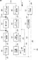
図1は、本発明を適用した符号化装置の主な構成例を示すブロック図である。図1に示される符号化装置100は、画像データを所定の符号化方式で符号化し、コードストリームを生成する装置である。符号化装置100は、制御部101、入力系111、画像符号化部112、および出力系113を有する。
<1. First Embodiment>
[Configuration of Encoding Device]
FIG. 1 is a block diagram showing a main configuration example of an encoding apparatus to which the present invention is applied. An
制御部101は、入力系111乃至出力系113を制御し、画像データの符号化に関する処理を実行させる。
The
入力系111は、任意のハードウェア資源により実現される1つまたは複数の処理部よりなる系である。入力系111は、制御部101により制御され、符号化処理の対象となる画像データに対して、例えば、記憶媒体から画像データを読み出したり、ネットワークを介して他の装置より送信された画像データを受信したりする等、任意の処理を行う。また、入力系111は、制御部101により制御され、矢印121に示されるように、任意の処理を施したその画像データを画像符号化部112に供給する。
The
画像符号化部112は、制御部101により制御され、矢印121に示されるように、入力系111より供給される画像データを取得する。また、画像符号化部112は、制御部101により制御され、取得した画像データを所定の方式で符号化してコードストリームを生成する。さらに、画像符号化部112は、制御部101により制御され、矢印122に示されるように、生成したコードストリームを出力系113に供給する。
The
出力系113は、任意のハードウェア資源により実現される1つまたは複数の処理部よりなる系である。出力系113は、制御部101により制御され、矢印122に示されるように、画像符号化部112より供給されるコードストリームを取得する。また、出力系113は、制御部101により制御され、取得したコードストリームに対して、例えば記憶媒体に記憶したり、ネットワークを介して他の装置に送信したりする等、任意の処理を行う。
The
制御部101は、矢印131に示されるように、入力系111から、入力系111が行う処理の処理速度を示す入力レート情報を取得する。同様に、制御部101は、矢印132に示されるように、出力系113から、出力系113が行う処理の処理速度を示す出力レート情報を取得する。さらに、制御部101は、矢印133に示されるように、画像符号化部112から、画像符号化部112が行う画像符号化処理の負荷量を示す負荷情報133を取得する。
The
また、制御部101は、矢印134に示されるように入力系111に制御情報を供給して入力系111の処理を制御する。さらに、制御部101は、矢印135に示されるように画像符号化部112に制御情報を供給して画像符号化処理を制御する。また、制御部101は、矢印136に示されるように出力系113に制御情報を供給して出力系113の処理を制御する。
Further, the
このとき、制御部101は、入力レート情報、出力レート情報、および負荷情報に基づいて、画像符号化部112が行う画像符号化処理の処理速度を決定する。
At this time, the
ここで処理速度とは、単位時間当たりの処理量(所謂スループット)である。この処理速度は、例えば、単位時間当たりに処理される画像データ(コードストリーム)のデータ量(所謂レート)により示される。つまり、入力レート情報は、入力系111において単位時間辺りに処理される画像データのデータ量(入力レート)を示す情報である。同様に、出力レート情報は、出力系113において単位時間辺りに処理される画像データのデータ量(出力レート)を示す情報である。
Here, the processing speed is a processing amount per unit time (so-called throughput). This processing speed is indicated, for example, by the data amount (so-called rate) of image data (code stream) processed per unit time. That is, the input rate information is information indicating the data amount (input rate) of image data processed per unit time in the
この入力レート情報は、入力系111に割り当てられたハードウェア資源の仕様であってもよいし、入力系111において実際に行われる処理の速度計測結果であってもよい。同様に、出力レート情報は、出力系113に割り当てられたハードウェア資源の仕様であってもよいし、出力系113において実際に行われる処理の速度計測結果であってもよい。
The input rate information may be a specification of hardware resources allocated to the
なお、入力レート情報および出力レート情報は、例えば単位時間当たりに処理されるデータ量のように、直接的にスループットを示す情報であってもよいが、例えばハードウェア資源の量のように、単位時間当たりの処理量に変換可能な、間接的にスループットを示す情報であってもよい。もちろん、入力レート情報および出力レート情報は、ハードウェア資源の仕様と速度計測結果を併用する等、複数の情報を含むようにしてもよい。 Note that the input rate information and the output rate information may be information that directly indicates the throughput, for example, the amount of data processed per unit time, but the unit, for example, the amount of hardware resources. Information indicating throughput indirectly that can be converted into a processing amount per time may be used. Of course, the input rate information and the output rate information may include a plurality of pieces of information such as a combination of hardware resource specifications and speed measurement results.
負荷情報は、画像符号化部112により行われる画像符号化処理の、予測される負荷の大きさを示す予測情報である。換言すれば、負荷情報は、画像符号化処理の処理速度(スループット)の予測値を示す。より具体的には、負荷情報は、例えば、画像データの符号化難易度を示す情報、過去の画像データのスループット、ハードウェア資源の割当量を示す情報、またはその他の設定情報等よりなる。つまり負荷情報は、画像符号化処理のスループットの予測値を求めることができる情報であればどのような情報であってもよい。
The load information is prediction information indicating the predicted load size of the image encoding process performed by the
制御部101は、負荷情報より求められる画像符号化処理の処理速度を、入力系111の処理の処理速度や、出力系113の処理の処理速度と比較し、それらの比較結果に基づいて画像符号化処理の処理速度を制御する。
The
例えば、制御部101は、画像符号化処理の処理速度が入力系111の処理の処理速度より速い場合、画像符号化処理の処理速度を入力系111の処理速度まで低下させる。また、例えば、制御部101は、画像符号化処理の処理速度が出力系113の処理の処理速度より速い場合、画像符号化処理の処理速度を出力系113の処理速度まで低下させる。さらに、例えば、制御部101は、画像符号化処理の処理速度が出力系113の処理の処理速度より遅い場合、画像符号化処理の処理速度を出力系113の処理速度まで上昇させる。
For example, when the processing speed of the image encoding process is faster than the processing speed of the
このように、制御部101は、入力系111や出力系113等、画像符号化部112の前段や後段の処理部が行う処理の処理速度も考慮して画像符号化処理の処理速度を決定するので、符号化装置100全体の処理速度を向上させるように画像符号化処理の処理速度を制御することができる。
As described above, the
このような制御により符号化装置100は、不要な負荷の増大を抑制するように、符号化処理にハードウェア資源を割り当てることができる。つまり、符号化装置100は、符号化処理においてハードウェア資源をより有効に活用することができる。
By such control, the
次に、このような符号化装置100の構成の具体的な例について説明する。
Next, a specific example of the configuration of such an
図2は、図1の符号化装置の具体的な例を示す図である。符号化装置100Aは、図1の符号化装置100の構成の具体的な一例を示す。図2に示されるように、符号化装置100Aは、制御部101と画像符号化部112がバス141に接続される。バス141には、さらに、記憶部142、キャッシュメモリ143、および入出力インタフェース144が接続される。
FIG. 2 is a diagram illustrating a specific example of the encoding device of FIG. 100 A of encoding apparatuses show a specific example of a structure of the
バス141は、バス141に接続される処理部間で授受されるデータの伝送媒体である。例えばPCIバス(Peripheral Components Interconnect bus)等により構成される。記憶部142は、データを記憶する記憶媒体である。例えば、ハードディスクやフラッシュメモリ等により構成される。
The
キャッシュメモリ143は、データを一時的に保持する記憶媒体である。例えばRAM(Random Access Memory)等の、記憶部142の読み出し速度や、入出力インタフェースの144のスループットに比べて高速にデータの授受が可能な半導体メモリにより構成される。
The
入出力インタフェース144は、符号化装置100Aのデータの授受を行う。入出力インタフェース144は、例えば、符号化装置100Aの外部のネットワーク151より供給されるデータを取得し、そのデータを、バス141を介してキャッシュメモリ143等に供給する。また、入出力インタフェース144は、例えば、画像符号化部112等からバス141を介して供給されるデータを取得し、そのデータを、ネットワーク151を介して他の装置に供給する。例えば、HDMI(High-Definition Multimedia Interface)、HD-SDI(High Definition Serial Digital Interface)、Ethernet(登録商標)(LAN(Local Area Network)ボード)等により構成される。
The input /
このような構成の符号化装置100Aにおいて、符号化対象の画像データは記憶部142に記憶されている。制御部101は、点線矢印161に示されるように、記憶部142からその画像データを読み出し、バス141を介してキャッシュメモリ143に供給させ、キャッシュメモリ143にその画像データを保持させる。
In the
制御部101は、また、点線矢印162に示されるように、キャッシュメモリ143に保持されている画像データを読み出し、バス141を介して画像符号化部112に供給させ、符号化させる。
The
制御部101は、さらに、点線163に示されるように、画像データが符号化されたコードストリームを、バス141を介して入出力インタフェース144に供給させ、入出力インタフェース144から外部のネットワーク151に出力させる。
Further, as indicated by a dotted
つまり、この符号化装置100Aにおいては、一点鎖線で示されるように、バス141、記憶部142、およびキャッシュメモリ143により入力系111が形成され、二点鎖線で示されるように、バス141および入出力インタフェース144により出力系113が形成される。
In other words, in this
入力系111において、一般的に、記憶部142からのデータの読み出しレートは、バス141の伝送レートやキャッシュメモリ143のデータ入出力レートより低い。従って、図1を参照して説明したように、制御部101は、画像符号化部112の画像符号化処理の処理速度(スループット)が記憶部142のデータ読み出し速度より速い場合、画像符号化部112の画像符号化処理の処理速度を減速させ、記憶部142のデータ読み出し速度(入力系111の処理速度)に合わせる。
In the
出力系113において、一般的に、入出力インタフェース144のデータの入出力レート(スループット)は、バス141の伝送レートより低い。従って、図1を参照して説明したように、制御部101は、画像符号化部112の画像符号化処理の処理速度(スループット)が入出力インタフェース144のデータの入出力速度より速い場合、画像符号化部112の画像符号化処理の処理速度を減速させ、入出力インタフェース144のデータ入出力速度(出力系113の処理速度)に合わせる。
In the
また、図1を参照して説明したように、制御部101は、画像符号化部112の画像符号化処理の処理速度(スループット)が入出力インタフェース144のデータの入出力速度より遅い場合、画像符号化部112の画像符号化処理の処理速度を加速させ、入出力インタフェース144のデータ入出力速度(出力系113の処理速度)に合わせる。
Further, as described with reference to FIG. 1, when the processing speed (throughput) of the image encoding process of the
このように制御部101が符号化処理を制御することにより、符号化装置100Aは、各部の処理速度を適切に調整し、不要な待機時間の発生を抑制することができる。すなわち、符号化装置100Aは、ハードウェア資源をより有効に利用して符号化処理を行うことができる。
As described above, the
図3は、図1の符号化装置100の他の具体的な例を示す図である。
FIG. 3 is a diagram illustrating another specific example of the
符号化装置100Bは、図1の符号化装置100の構成の、他の具体的な一例を示す。図3に示されるように、符号化装置100Bは、制御部101と画像符号化部112がバス141に接続される。バス141には、さらに、キャッシュメモリ143、および入出力インタフェース144が接続される。
The
このような構成の符号化装置100Bにおいて、符号化対象の画像データはネットワーク151を介して他の装置より供給される。制御部101は、点線矢印171に示されるように、入出力インタフェース144を制御して、その画像データを取得し、バス141を介してキャッシュメモリ143に供給させ、キャッシュメモリ143にその画像データを保持させる。
In the
制御部101は、また、点線矢印172に示されるように、キャッシュメモリ143に保持されている画像データを読み出し、バス141を介して画像符号化部112に供給させ、符号化させる。
The
制御部101は、さらに、点線173に示されるように、画像データが符号化されたコードストリームを、バス141を介して入出力インタフェース144に供給させ、入出力インタフェース144から外部のネットワーク151に出力させる。
Further, as indicated by a dotted
つまり、この符号化装置100Bにおいては、一点鎖線で示されるように、バス141、キャッシュメモリ143、および入出力インタフェース144により入力系111が形成され、二点鎖線で示されるように、バス141および入出力インタフェース144により出力系113が形成される。
That is, in this
入力系111において、一般的に、入出力インタフェース144のデータの入出力レート(スループット)は、バス141の伝送レートやキャッシュメモリ143のデータ入出力レートより低い。従って、図1を参照して説明したように、制御部101は、画像符号化部112の画像符号化処理の処理速度(スループット)が入出力インタフェース144のデータの入出力速度より速い場合、画像符号化部112の画像符号化処理の処理速度を減速させ、入出力インタフェース144のデータ入出力速度(入力系111の処理速度)に合わせる。
In the
また、図2の場合と同様に、制御部101は、画像符号化部112の画像符号化処理の処理速度(スループット)が入出力インタフェース144のデータの入出力速度より速い場合、画像符号化部112の画像符号化処理の処理速度を減速させ、入出力インタフェース144のデータ入出力速度(出力系113の処理速度)に合わせる。
Similarly to the case of FIG. 2, when the processing speed (throughput) of the image encoding process of the
さらに、図2の場合と同様に、制御部101は、画像符号化部112の画像符号化処理の処理速度(スループット)が入出力インタフェース144のデータの入出力速度より遅い場合、画像符号化部112の画像符号化処理の処理速度を加速させ、入出力インタフェース144のデータ入出力速度(出力系113の処理速度)に合わせる。
Further, as in the case of FIG. 2, the
このように制御部101が符号化処理を制御することにより、符号化装置100Bは、各部の処理速度を適切に調整し、不要な待機時間の発生を抑制することができる。すなわち、符号化装置100Bは、ハードウェア資源をより有効に利用して符号化処理を行うことができる。
As described above, the
次に、このような制御を行う制御部101について説明する。図4は、制御部の主な構成例を示すブロック図である。図4に示されるように、制御部101は、入力レート情報取得部181、出力レート情報取得部182、符号化処理制御部183、負荷情報取得部184、負荷制御部185、および記憶部186を有する。
Next, the
入力レート情報取得部181は、入力系111を構成するデバイスより、入力系111のスループットを示す入力レート情報191を取得し、それを記憶部186に記憶させる。出力レート情報取得部182は、出力系113を構成するデバイスより、出力系113のスループットを示す出力レート情報192を取得し、それを記憶部186に記憶させる。
The input rate information acquisition unit 181 acquires
なお、この入力レート情報191および出力レート情報192は、入力系111または出力系113において計測された値であってもよいが、入力系111または出力系113を構成するデバイスの仕様であってもよい。したがって、入力系111および出力系113を構成するデバイスが予め定められており、それらのデバイスの仕様を入力レート情報191および出力レート情報192とする場合、入力レート情報191および出力レート情報192は、例えば工場出荷時等に予め記憶部186に記憶させておくようにしてもよい。その場合、入力レート情報取得部181および出力レート情報取得部182は、省略することができる。
Note that the
符号化処理制御部183は、画像符号化部112による画像データの符号化処理を制御する。符号化処理制御部183は、負荷制御部185において決定された負荷量となるように、符号化処理のスループットを制御する。
The encoding
負荷情報取得部184は、画像符号化部112の画像符号化処理の負荷の大きさ(負荷量)の予測値を示す負荷情報を取得する。例えば、負荷情報取得部184は、この負荷情報として、画像符号化処理のスループットの予測値を直接的または間接的に示すスループット情報193を取得する。スループット情報193の内容は任意であるが、例えば、画像データの符号化の難易度を示す情報や、過去の符号化処理の単位時間当たりの処理量等により構成される。負荷情報取得部184は、取得した負荷情報を負荷制御部185に供給する。
The load
負荷制御部185は、記憶部186から入力レート情報191および出力レート情報192を読み出し、それらと、負荷情報取得部184から供給された負荷情報(スループット情報193)とに基づいて、画像符号化部112による画像符号化処理の負荷量を決定する。負荷制御部185は、符号化処理制御部183を制御することにより、決定した負荷量となるように画像符号化処理のスループットを制御する。
The
記憶部186は、例えばRAM等の半導体メモリにより構成される記憶媒体であり、入力レート情報191や出力レート情報192等の情報を記憶する。
The
[処理の流れ]
次に、以上のような符号化装置100において実行される各種処理の流れについて説明する。最初に、制御部101による符号化制御処理の流れの例を、図5のフローチャートを参照して説明する。
[Process flow]
Next, the flow of various processes executed in the
符号化制御処理が開始されると、制御部101の入力レート情報取得部181は、ステップS101において、入力レート情報を取得する。ステップS102において、出力レート情報取得部182は、出力レート情報を取得する。ステップS103において、符号化処理制御部183は、画像データを入力系111(例えばキャッシュメモリ143)から読み出し、画像符号化部112に入力させる。
When the encoding control process is started, the input rate information acquisition unit 181 of the
ステップS104において、符号化処理制御部183は、画像符号化部112を制御し、入力させた画像データを符号化する画像符号化処理を実行させる。ステップS105において、負荷情報取得部184は、その符号化処理についてスループット情報193を取得する。
In step S104, the encoding
ステップS106において、負荷制御部185は、入力レートまたは出力レートのうち、少なくともいずれか一方に基づいて、ステップS104の制御によって実行された画像符号化処理のスループットを制御する。
In step S106, the
ステップS107において、符号化処理制御部183は、画像符号化処理により生成されたコードストリームを出力系113に出力し、処理させる。
In step S107, the encoding
ステップS108において、符号化処理制御部183は、符号化制御処理を終了するか否かを判定する。例えば未処理の画像データが入力系111(例えばキャッシュメモリ143)に存在する等して、符号化制御処理を終了しないと判定された場合、ステップS101に処理が戻り、それ以降の処理が繰り返される。
In step S108, the encoding
このとき、入力レートが固定値の場合、ステップS101の処理は省略可能である。同様に、出力レートが固定値の場合、ステップS102の処理は省略可能である。 At this time, if the input rate is a fixed value, the process of step S101 can be omitted. Similarly, when the output rate is a fixed value, the process of step S102 can be omitted.
ステップS108において、例えば未処理の画像データが入力系111(例えばキャッシュメモリ143)に存在せず、符号化制御処理を終了すると判定された場合、符号化制御処理が終了される。 In step S108, for example, when it is determined that the unprocessed image data does not exist in the input system 111 (for example, the cache memory 143) and the encoding control process is to be ended, the encoding control process is ended.
なお、ステップS105の処理(スループット情報の取得)は、その情報の内容に応じて適切なタイミングで行われる。したがって、例えば、ステップS104の処理より先にステップS105およびステップS106の処理が行われるようにしてもよい。また、例えば、画像符号化処理実行途中において、ステップS105およびステップS106の処理が行われるようにしてもよい。 Note that the processing of step S105 (acquisition of throughput information) is performed at an appropriate timing according to the content of the information. Therefore, for example, the processing of step S105 and step S106 may be performed prior to the processing of step S104. Further, for example, the processing of step S105 and step S106 may be performed during the execution of the image encoding processing.
次に、図5のステップS106において実行される負荷制御処理の詳細な流れの例について、図6のフローチャートを参照して説明する。 Next, an example of a detailed flow of the load control process executed in step S106 of FIG. 5 will be described with reference to the flowchart of FIG.
負荷制御処理が開始されると、負荷制御部185は、ステップS121において、入力レート情報191およびスループット情報193に基づいて、符号化処理のスループットが入力レートより高いか否かを判定する。
When the load control process is started, the
符号化処理のスループットが入力レートより高いと判定された場合、処理はステップS122に進む。この場合、画像符号化処理の処理速度が速すぎて、入力系111からの画像データの供給が追いつかない。つまり、画像符号化処理がハードウェア資源を不要に消費している。そこで、負荷制御部185は、ステップS122において、画像符号化部112の画像符号化処理の処理速度を減速させ、画像符号化処理のスループットを入力レートまで低下させる。ステップS122の処理が終了すると、図5のステップS106に戻り、それ以降の処理が実行される。
If it is determined that the throughput of the encoding process is higher than the input rate, the process proceeds to step S122. In this case, the processing speed of the image encoding process is too high, and the supply of image data from the
符号化処理のスループットが入力レートより高くないと判定された場合、処理はステップS123に進む。負荷制御部185は、ステップS123において、出力レート情報192およびスループット情報193に基づいて、符号化処理のスループットが出力レートより高いか否かを判定する。
If it is determined that the throughput of the encoding process is not higher than the input rate, the process proceeds to step S123. In step S123, the
符号化処理のスループットが出力レートより高いと判定された場合、処理はステップS124に進む。この場合、画像符号化処理の処理速度が速すぎて、出力系113における処理がオーバフローする恐れがある。つまり、画像符号化処理がハードウェア資源を不要に消費している。そこで、負荷制御部185は、ステップS124において、画像符号化部112の画像符号化処理の処理速度を減速させ、画像符号化処理のスループットを出力レートまで低下させる。ステップS124の処理が終了すると、図5のステップS106に戻り、それ以降の処理が実行される。
If it is determined that the throughput of the encoding process is higher than the output rate, the process proceeds to step S124. In this case, there is a possibility that the processing speed of the image encoding process is too fast and the process in the
符号化処理のスループットが出力レートより高くないと判定された場合、処理はステップS125に進む。負荷制御部185は、ステップS125において、出力レート情報192およびスループット情報193に基づいて、符号化処理のスループットが出力レートより低いか否かを判定する。
If it is determined that the throughput of the encoding process is not higher than the output rate, the process proceeds to step S125. In step S125, the
符号化処理のスループットが出力レートより低いと判定された場合、処理はステップS126に進む。この場合、画像符号化処理の処理速度が遅すぎて、出力系113において処理の無駄な空き時間(待機時間)が生じる。つまり、画像符号化処理のハードウェア資源の消費量が少なすぎる。ハードウェア資源に余裕があるのであれば、さらに画像符号化処理がハードウェア資源を消費するようにすることにより、符号化装置100のスループットを向上させることができる。そこで、負荷制御部185は、ステップS126において、画像符号化部112の画像符号化処理の処理速度を加速させ、画像符号化処理のスループットを出力レートまで上昇させる。ステップS126の処理が終了すると、図5のステップS106に戻り、それ以降の処理が実行される。
If it is determined that the throughput of the encoding process is lower than the output rate, the process proceeds to step S126. In this case, the processing speed of the image encoding process is too slow, and a wasteful idle time (standby time) of processing occurs in the
符号化処理のスループットが出力レートより低くないと判定された場合、負荷制御処理が終了され、図5のステップS106に戻り、それ以降の処理が実行される。 If it is determined that the throughput of the encoding process is not lower than the output rate, the load control process is terminated, the process returns to step S106 in FIG. 5, and the subsequent processes are executed.
以上のような制御処理が行われることにより、符号化装置100は、符号化処理においてハードウェア資源をより有効に活用することができる。
By performing the control process as described above, the
なお、図6においては、ステップS121、ステップS123、またはステップS125の各判定処理を、図6に示されるフローチャートの順に行うように説明したが、各判定条件の優先順位は任意であり、どの判定から行うようにしてもよい。また、複数の判定を満たすときのみ符号化処理のスループットの制御(例えば、ステップS122、ステップS124、またはステップS126)を行うようにしてもよい。 In FIG. 6, it has been described that each determination process of step S121, step S123, or step S125 is performed in the order of the flowchart shown in FIG. 6, but the priority order of each determination condition is arbitrary, and which determination You may make it perform from. Also, the throughput of the encoding process (for example, step S122, step S124, or step S126) may be performed only when a plurality of determinations are satisfied.
<2.第2の実施の形態>
[画像符号化部の構成]
画像符号化部112の符号化方法は任意であり、例えば、JPEG(Joint Photographic Experts Group)、MPEG(Moving Picture Experts Group)、AVC(Advanced Video Coding)、JPEG-LS(Lossless JPEG)、または、JPEG2000 Losslessなどであってもよいし、これら以外の方法であっても良い。
<2. Second Embodiment>
[Configuration of Image Encoding Unit]
The encoding method of the
以下に符号化方式がJPEG2000の場合について説明する。図7は、画像符号化部112の主な構成例を示すブロック図である。図7に示されるように、画像符号化部112は、DCレベルシフト部201、ウェーブレット変換部202、量子化部203、コードブロック化部204、およびビットプレーン展開部205を有する。
The case where the encoding method is JPEG2000 will be described below. FIG. 7 is a block diagram illustrating a main configuration example of the
DCレベルシフト部201は、後段のウェーブレット変換を効率的に行うために、矢印231のように画像符号化部112に入力された画像データのDC成分のレベルシフトを行う。例えば、RGB信号が正の値(符号無しの整数)を持っている。そこで、DCレベルシフト部201は、そのことを利用し、原信号のダイナミックレンジを半分にするレベルシフトを行うことで、圧縮効率の向上を図る。従ってYCbCr信号のCbやCr(色差信号)の様に符号(正負両方あり)の整数値を持つ信号を原信号とする場合、このレベルシフトは行われない。
The DC
ウェーブレット変換部202は、通常低域フィルタと高域フィルタから構成されるフィルタバンクによって実現される。また、デジタルフィルタは通常複数タップ長のインパルス応答(フィルタ係数)を有するので、ウェーブレット変換部122は、フィルタリングが行えるだけの入力画像を予めバッファリングするバッファを有する。
The
ウェーブレット変換部202は、矢印232のようにDCレベルシフト部201より出力された画像データを、フィルタリングに最低限必要なデータ量以上取得すると、そのDCレベルシフト後の画像データに対して、所定のウェーブレット変換フィルタを用いてフィルタリングを行い、ウェーブレット係数を生成する。なお、ウェーブレット変換部202は、画像の垂直方向および水平方向のそれぞれに対して、画像データを低域成分と高域成分に分離するフィルタリングを行う。
When the
そして、ウェーブレット変換部202は、このようなフィルタリング処理を、図8に示されるように、垂直方向および水平方向の両方において低域成分として分離されたサブバンドに対して再帰的に所定回数繰り返す。これは、画像のエネルギーの多くが低域成分に集中しているからである。
Then, the
図8は、分割レベル数3のウェーブレット変換処理により生成されるサブバンドの構成例を示す図である。この場合、ウェーブレット変換部202は、まず、画像全体をフィルタリングし、サブバンド3LL(図示せず)、3HL、3LH、および3HHを生成する。次に、ウェーブレット変換部202は、生成されたサブバンド3LLに対して再度フィルタリングを行い、2LL(図示せず)、2HL、2LH、および2HHを生成する。さらに、ウェーブレット変換部122は、生成されたサブバンド2LLに対して再度フィルタリングを行い、0LL、1HL、1LH、および1HHを生成する。
FIG. 8 is a diagram illustrating a configuration example of subbands generated by the wavelet transform process of the
ウェーブレット変換部202は、フィルタリングにより得られたウェーブレット係数を、サブバンド毎に、矢印233に示されるように量子化部203に供給する。量子化部203は、供給されたウェーブレット係数を量子化する。この量子化の方法は任意であるが、量子化ステップサイズで除算するスカラ量子化が一般的である。量子化部203は、量子化により得られた量子化係数を、矢印234に示されるように、コードブロック化部204に供給する。なお、これより後段においては、ウェーブレット係数の代わりに量子化係数が供給されることになるが、この量子化係数もウェーブレット係数の場合と基本的に同様に扱われる。したがって、以下においては、必要でない限りその点についての説明は省略し、単に係数または係数データと称する。
The
なお、画像符号化部112が、復号処理により元のデータを完全に復元可能な可逆符号化方式により画像データを符号化する場合、この量子化部203の処理は省略され、矢印235に示されるように、ウェーブレット変換部202の出力がコードブロック化部204に供給される。
When the
ウェーブレット係数は、コードブロック化部204で、エントロピ符号化の処理単位である所定の大きさのコードブロックに分割される。図9は各サブバンド中のコードブロックの位置関係を示したものである。例えば64×64画素程度のサイズのコードブロックが、分割後のすべてのサブバンド中に生成される。図4の例において、最も分割レベルが小さい3HHのサブバンドの大きさが例えば640×320画素であるとすると、64×64画素のコードブロックは合計50個存在することになる。後段の各処理部は、このコードブロック毎に処理を行う。
The wavelet coefficients are divided into code blocks having a predetermined size, which is a processing unit of entropy coding, by the
コードブロック化部204は、矢印236に示されるように、各コードブロックをビットプレーン展開部205に供給する。ビットプレーン展開部205は、係数データを、ビットの位毎のビットプレーンに展開する。
The code
ビットプレーンは、所定の数のウェーブレット係数よりなる係数群を、1ビット毎、つまり位毎に分割(スライス)したものである。つまり、ビットプレーンは、その係数群の互いに同一の位のビット(係数ビット)の集合である。 The bit plane is obtained by dividing (slicing) a coefficient group including a predetermined number of wavelet coefficients for each bit, that is, for each rank. That is, the bit plane is a set of bits (coefficient bits) at the same position in the coefficient group.
図10にその具体例を示す。図10の左図は縦4個、横4個の計16個の係数を示している。この16個の係数のうち、絶対値が最大のものは13で、2進数で1101と表現される。ビットプレーン展開部205は、このような係数群を、絶対値を示す4枚のビットプレーン(絶対値のビットプレーン)と、符号を示す1枚のビットプレーン(符号のビットプレーン)に展開する。つまり、図10中左の係数群は、図10中右に示されるように、4枚の絶対値のビットプレーンと1枚の符号のビットプレーンに展開される。ここで、絶対値のビットプレーンの要素はすべて0か1の値をとる。また、符号を示すビットプレーンの要素は、係数の値が正であることを示す値、係数の値が0であることを示す値、または係数の値がマイナスを示す値のいずれかをとる。
FIG. 10 shows a specific example. The left diagram of FIG. 10 shows a total of 16 coefficients, 4 vertical and 4 horizontal. Among these 16 coefficients, the coefficient having the maximum absolute value is 13, which is expressed as 1101 in binary. The bit
画像符号化部112は、さらに、ビットモデリング部206、算術符号化部207、符号量加算部208、制御部209、ヘッダ生成部210、およびパケット生成部211を有する。
The
ビットプレーン展開部205は、展開したビットプレーンを、矢印237に示されるように、ビットモデリング部206に供給する。
The bit
ビットモデリング部206および算術符号化部207は、EBCOT(Embedded Coding with Optimized Truncation)部221として動作し、入力される係数データに対して、JPEG2000規格で定められたEBCOTと呼ばれるエントロピ符号化を行う。EBCOTは、所定の大きさのブロック毎にそのブロック内の係数の統計量を測定しながら符号化を行う手法である。
The
ビットモデリング部206は、JPEG2000規格で定められた手順に従って、係数データに対してビットモデリングを行い、矢印238に示されるように算術符号化部207にコンテキストを送出する。算術符号化部207は、係数のビットプレーンを算術符号化する。
The
コードブロックの縦横のサイズは4から256まで2のべき乗で、通常使用される大きさは、32×32、64×64、128×32等がある。係数値がnビットの符号付き2進数で表されていて、bit0からbit(n−2)がLSBからMSBまでのそれぞれのビットを表すとする。残りの1ビットは符号を示す。符号ブロックの符号化は、MSB側のビットプレーンから順番に、例えばSignificant Propagation Pass、Magnitude Refinement Pass、およびCleanup Passの3種類の符号化パスによって行われる。
The vertical and horizontal sizes of the code block are powers of 2 from 4 to 256, and commonly used sizes include 32 × 32, 64 × 64, 128 × 32, and the like. Assume that the coefficient value is represented by an n-bit signed binary number, and
算術符号化部207は、生成したコードストリームを、矢印239に示されるように、符号量加算部208に供給する。符号量加算部208は、そのコードストリームの符号量をカウントし、累積する。そして、符号量加算部208は、そのコードストリームを、矢印242および矢印243に示されるように、ヘッダ作成部210およびパケット生成部211に供給するとともに、矢印240に示されるように、符号量の累積値を制御部209に供給する。制御部209は、供給された符号量の累積値と目標符号量とを比較し、累積値が目標符号量より小さい場合、矢印241に示されるように、EBCOT部221を制御し、次のビットプレーンの符号化を行わせる。EBCOT部221は、その制御に従って次に重要なビットプレーンを符号化し、生成したコードストリームを符号量加算部208に供給する。符号量加算部208は、そのコードストリームの符号量をカウントして累積し、累積値を制御部209に供給する。
The
累積値が目標符号量に達するまで、以上のような処理が繰り返される。そして、累積値が目標符号量に達すると、制御部209は、EBCOT部221を制御し、符号化処理を終了させる。
The above processing is repeated until the accumulated value reaches the target code amount. When the accumulated value reaches the target code amount, the
パケット生成部211は、供給された符号化コードストリームをパケット化する。ヘッダ生成部210は、そのパケットのヘッダ情報を生成し、そのヘッダ情報を矢印244に示されるように、パケット生成部211に供給する。パケット生成部211は、そのヘッダ情報を用いてパケット化を行う。生成されたパケットは矢印245に示されるように、画像符号化部112の外部に出力される。
The
[制御部の構成]
次に、このような画像符号化部112を制御する制御部について説明する。図11は、制御部の主な構成例を示すブロック図である。図11において、制御部101は、基本的に図4を参照して説明した場合と同様の構成を有する。すなわち、制御部101は、符号化処理制御部183乃至記憶部186を有する。
[Configuration of control unit]
Next, a control unit that controls the
ただし、この場合、制御部101の負荷情報取得部184は、負荷情報として、画像符号化部112からゼロビットプレーン数251を取得する。
However, in this case, the load
ゼロビットプレーンは、画像符号化部112のビットプレーン展開部205により展開された各ビットプレーンのうち、MSBから連続する、係数が全てゼロのビットプレーンのことを示す。つまり、ゼロビットプレーン数は、全ての係数がゼロであるビットプレーンのMSBからの連続数を示す。この値は、ビットプレーン展開部205がコードブロックをビットプレーンに展開した時点で決定される。負荷情報取得部184は、このように生成されるゼロビットプレーン数251を、画像符号化部112のビットプレーン展開部205より取得する。
The zero bit plane indicates a bit plane that is continuous from the MSB and has all zero coefficients among the bit planes expanded by the bit
図12は、ゼロビットプレーンの例を説明する図である。図12に示されるように、ゼロビットプレーン数251は、コードブロック毎に算出される。各コードブロックのビット深度Hからこのゼロビットプレーン数(NUM_ZB)(図12中空白部分)を減算することにより、各コードブロックの有効ビットプレーン数(NUM_BP)(図12中斜線部分)が算出される。この有効ビットプレーン数は、各コードブロックのおおよその情報量を示す。すなわち、各コードブロックのおおよその符号化の難易度を示す。
FIG. 12 is a diagram illustrating an example of a zero bit plane. As shown in FIG. 12, the number of zero
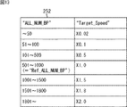
記憶部186には、入力レート情報191や出力レート情報192の代わりに、テーブル情報252が記憶されている。テーブル情報252は、有効ビットプレーン数のピクチャ内の総和(ALL_NUM_BP)から画像符号化処理の処理速度の制御量を決定するためのテーブル情報である。このテーブル情報252において、有効ビットプレーン数のピクチャ毎の総和と画像符号化処理の処理速度の制御量との対応関係は、入力レートと出力レートを考慮して作成されている。
The
図13は、有効ビットプレーン数から処理速度の補正量を求めるためのテーブル情報の例を説明する図である。 FIG. 13 is a diagram for explaining an example of table information for obtaining the correction amount of the processing speed from the number of effective bit planes.
図13に示されるように、テーブル情報252においては、有効ビットプレーン数の総和(ALL_NUM_BP)の取り得る値が複数の範囲に区切られ、各範囲に対して、画像符号化処理の処理速度の補正量が割り当てられている。例えば、図13の例の場合、有効ビットプレーン数の総和(ALL_NUM_BP)が「501」乃至「1000」であるときを標準値とし、画像符号化処理の処理速度を変更しない(×1.0倍)とする。また、これより、有効ビットプレーン数の総和(ALL_NUM_BP)が大きい場合はその値に応じて処理速度を加速させ、有効ビットプレーン数の総和(ALL_NUM_BP)が小さい場合はその値に応じて処理速度を減速させるようになされている。
As shown in FIG. 13, in the
つまり、負荷制御部185は、負荷情報取得部184が取得したコードブロック毎のゼロビットプレーン数251から、各コードブロックの有効ビットプレーン数を求め、さらにその有効ビットプレーン数の総和をピクチャ毎に求める。負荷制御部185は、さらに、記憶部186より読み出したテーブル情報252を用いて、その有効ビットプレーン数の総和に対応する画像符号化処理の処理速度の制御量を求め、符号化処理制御部183を制御する。このようにすることにより、負荷制御部185は、入力レート、出力レート、および負荷情報に基づいて、画像符号化処理の負荷量を制御することになる。
That is, the
したがって、上述した場合と同様に、符号化装置100は、符号化処理においてハードウェア資源をより有効に活用することができる。
Therefore, as in the case described above, the
なお、この場合、図4の入力レート情報取得部181および出力レート情報取得部182は、省略される。 In this case, the input rate information acquisition unit 181 and the output rate information acquisition unit 182 in FIG. 4 are omitted.
[処理の流れ]
次にこの場合の符号化制御処理の流れの例を図14のフローチャートを参照して説明する。
[Process flow]
Next, an example of the flow of the encoding control process in this case will be described with reference to the flowchart of FIG.
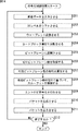
符号化制御処理が開始されると、符号化処理制御部183は、ステップS201において、入力系111(例えばキャッシュメモリ143)から画像データを画像符号化部112に入力させる。
When the encoding control process is started, the encoding
ステップS202において、符号化処理制御部183は、DCレベルシフト部201に、DCレベルをシフトさせる。ステップS203において、符号化処理制御部183は、ウェーブレット変換部202にウェーブレット変換させる。また、非可逆符号化方式の場合、符号化処理制御部183は、量子化部203にウェーブレット係数を量子化させる。ステップS204において、符号化処理制御部183は、コードブロック化部204に、係数をコードブロック単位で分割させる。ステップS205において、符号化処理制御部183は、ビットプレーン展開部205に、コードブロック毎の係数をビットプレーンに展開させる。
In step S202, the encoding
ステップS206において、負荷情報取得部184は、ビットプレーン展開部205より各コードブロックのゼロビットプレーン数251を取得する。負荷制御部185は、ステップS207において、ゼロビットプレーン数251から、有効ビットプレーン数のピクチャ毎の総和を算出する。負荷制御部185は、ステップS208において、テーブル情報252を参照し、有効ビットプレーン数のピクチャ毎の総和(ALL_NUM_BP)に基づいて画像符号化処理のスループットを制御する。
In step S206, the load
ステップS209において、符号化処理制御部183は、EBCOT部221等を制御し、負荷制御部185により決定されたスループットでエントロピ符号化を行わせる。
In step S209, the encoding
符号化処理制御部183は、ヘッダ生成部210およびパケット生成部211を制御し、ステップS210において、パケットを生成させ、ステップS211において、そのパケットを出力系113に出力させる。
The encoding
ステップS212において、符号化処理制御部183は、符号化制御処理を終了するか否かを判定する。終了しないと判定された場合、ステップS201に戻り、それ以降の処理が繰り返される。また、ステップS212において、符号化制御処理を終了すると判定された場合、符号化制御処理が終了される。
In step S212, the encoding
このように制御が行われることにより、符号化装置100は、符号化処理においてハードウェア資源をより有効に活用することができる。
By performing the control in this way, the
なお、図7の画像符号化部112において、EBCOT221の処理の負荷が非常に大きく、DCレベルシフト部201乃至ビットプレーン展開部205の各処理は、それに比べて負荷が軽い。従って、ビットプレーン展開時に、その有効ビットプレーン数から画像符号化処理のスループットを求めることにより、制御部101は、画像符号化処理をより高速に制御することができ、遅延時間の増大を抑制することができる。
In the
また、特に、可逆符号化の場合、非可逆符号化に比べて、画像データの符号化の難易度による符号化処理の負荷の増減が大きい。したがって、ハードウェア資源を不要に消費する恐れが大きい。しかしながら、制御部101が、上述したように制御を行うことにより、ピクチャ単位で画像符号化処理の負荷量を制御することができるので、可逆符号化の場合も、ハードウェア資源をより有効に活用することができる。
In particular, in the case of lossless encoding, an increase or decrease in the load of the encoding process due to the difficulty of encoding image data is larger than in lossy encoding. Therefore, there is a high risk of consuming hardware resources unnecessarily. However, since the
以上における画像符号化処理のスループットの制御方法は任意である。例えば、画像符号化処理のクロックの速度を変更するようにしてもよいし、画像符号化処理の実行に割り当てる時間を増減させても良いし、符号化方法を変更するようにしてもよい。 The method for controlling the throughput of the image encoding process described above is arbitrary. For example, the clock speed of the image encoding process may be changed, the time allocated to the execution of the image encoding process may be increased or decreased, and the encoding method may be changed.
また、例えば、画像符号化部112の画像符号化処理をソフトウェアにより実現させるようにしてもよく、その場合、制御部101が、画像符号化処理に割り当てるハードウェア資源の量を増減させることにより、画像符号化処理のスループットを制御するようにしてもよい。例えば、複数のCPU、複数のコアを有するCPU(Central Processing Unit)、またはマルチスレッド対応のCPUを用いて画像符号化処理を実行させる場合、制御部101は、画像符号化処理に割り当てるCPU数、コア数、またはスレッド数を増減させることにより、画像符号化処理のスループットを制御するようにしてもよい。
Further, for example, the image encoding process of the
<3.第3の実施の形態>
[ハードウェア資源の構成]
以下に、複数コアを有するCPUを用いて画像符号化処理を行う場合のハードウェア資源割り当て方法の様子について説明する。図15は、このときのハードウェア資源の例を説明するブロック図である。
<3. Third Embodiment>
[Hardware resource configuration]
Hereinafter, a description will be given of a hardware resource allocation method in a case where image encoding processing is performed using a CPU having a plurality of cores. FIG. 15 is a block diagram illustrating an example of hardware resources at this time.
図15に示されるように、情報処理システム300は、画像符号化処理を実現する情報処理装置301を有する。その情報処理装置301には、PCIバス302を介して各種装置が接続される。例えば、記憶装置303や、複数台のビデオテープレコーダ(VTR)であるVTR304−1乃至VTR304−Sが接続される。また、ユーザがこれらに対する操作入力を行うためのマウス305、キーボード306、並びに操作コントローラ307等も接続される。情報処理システム300は、これらの各装置により構成されるシステムであり、インストールされたプログラムによって、画像符号化処理や画像復号処理等を行うシステムである。
As illustrated in FIG. 15, the
例えば情報処理システム300の情報処理装置301は、大容量の記憶装置303に記憶されている動画コンテンツを読み出して符号化し、得られた符号化データを記憶装置303に書き戻すことができるようになされている。さらに、情報処理装置301は、符号化処理により得られた符号化データをVTR304−1乃至VTR304−Sを介してビデオテープに記録したりすることができるようにもなされている。また、情報処理装置301は、VTR304−1乃至VTR304−Sに装着されたビデオテープに記録された動画コンテンツを記憶装置303に取り込み得るようにもなされている。その際、情報処理装置301が、動画コンテンツを符号化するようにしてもよい。
For example, the
情報処理装置301は、マイクロプロセッサ401、GPU(Graphics Processing Unit)402の他に、XDR(Extreme Data Rate)-RAM(Random Access Memory)403やサウスブリッジ404を有している。また、情報処理装置301は、HDD(Hard Disk Drive)405、USB(Universal Serial Bus)インタフェース(USB I/F)406、およびサウンド入出力コーデック407を有している。
The
GPU402は専用のバス411を介してマイクロプロセッサ401に接続される。XDR-RAM403は専用のバス412を介してマイクロプロセッサ401に接続される。サウスブリッジ404は、専用のバスを介してマイクロプロセッサ401のI/Oコントローラ444に接続される。このサウスブリッジ404には、HDD405、USBインタフェース406、および、サウンド入出力コーデック407も接続されている。このサウンド入出力コーデック407にはスピーカ421が接続されている。また、GPU402にはディスプレイ422が接続される。サウスブリッジ404には、さらに、PCIバス302を介して、マウス305、キーボード306、VTR304−1乃至VTR304−S、記憶装置303、並びに、操作コントローラ307が接続される。
The
マウス305およびキーボード306は、ユーザの操作入力を受け、PCIバス302およびサウスブリッジ404を介して、ユーザの操作入力の内容を示す信号を、マイクロプロセッサ401に供給する。記憶装置303およびVTR304−1乃至VTR304−Sは、所定のデータを記録または再生できるようになされている。PCIバス302にはさらに、必要に応じてドライブ308が接続され、磁気ディスク、光ディスク、光磁気ディスク、或いは半導体メモリなどのリムーバブルメディア311が適宜装着され、それらから読み出されたコンピュータプログラムが、必要に応じてHDD405にインストールされる。
The
マイクロプロセッサ401は、OS(Operating System)等の基本プログラムを実行する汎用のメインCPUコア441を有する。また、メインCPUコア441には、共有バス445を介して複数(この場合8個)のRISC(Reduced Instruction Set Computer)タイプの信号処理プロセッサである、サブCPUコア442−1乃至サブCPUコア442−8が接続される。また、共有バス445には、例えば256[MByte]の容量を持つXDR-RAM403に対するメモリコントロールを行うメモリコントローラ443も接続される。さらに、共有バス445には、サウスブリッジ404との間でデータの入出力を管理するI/O(In/Out)コントローラ444も接続される。マイクロプロセッサ401は、これらの構成が1チップに集積された、マルチコア構成のプロセッサである。マイクロプロセッサ401の動作周波数は、例えば4[GHz]である。
The
このマイクロプロセッサ401は、起動時、HDD405に格納された制御プログラムに基づき、HDD405に格納されている必要なアプリケーションプログラムを読み出してXDR-RAM403に展開し、この後このアプリケーションプログラム及びオペレータ操作に基づいて必要な制御処理を実行する。また、マイクロプロセッサ401は、ソフトウェアを実行することにより符号化処理や復号処理を実現する。例えば、マイクロプロセッサ401は、エンコードの結果得られた符号化ストリームを、サウスブリッジ404を介してHDD405に供給して記憶させることができる。また、マイクロプロセッサ401は、例えば、デコードした結果得られる動画像コンテンツの再生映像を、GPU402へデータ転送し、ディスプレイ422に表示させることができる。
At startup, the
マイクロプロセッサ401内の各CPUコアの使用方法は任意であるが、例えば、メインCPUコア441が、制御部101の処理を行い、8個のサブCPUコア442−1乃至サブCPUコア442−8がそれぞれ、画像符号化部112の画像符号化処理を行う。このような情報処理システム300のマイクロプロセッサ401における8個のサブCPUコア442−1乃至サブCPUコア442−8のそれぞれには、キャッシュメモリが内蔵されている。つまり、8個のサブCPUコア442−1乃至サブCPUコア442−8は、それぞれ、各自の内部メモリであるキャッシュメモリと外部メモリであるXDR-RAM403の両方を利用することができる。
Although the usage method of each CPU core in the
なお、以下において、サブCPUコア442−1乃至サブCPUコア442−8を互いに区別して説明する必要の無い場合、サブCPUコア442と称する。このサブCPUコア442の数は、図15においては8個設けられるように示されているが、実際には任意である。各サブCPUコア442には、事前に、メインCPUコア441により画像符号化処理を行うためのソフトウェアプログラムが割り当てられる(キャッシュメモリにロードされる)。各サブCPUコア442は、割り当てられたソフトウェアプログラムを実行することにより、符号化処理を実現する。
In the following, the sub CPU cores 442-1 to 442-8 are referred to as sub CPU cores 442 when it is not necessary to distinguish them from each other. The number of sub CPU cores 442 is shown as being eight in FIG. 15, but is actually arbitrary. A software program for performing image coding processing by the
[制御部の構成]
図16は、図15に示されるようなハードウェア資源を用いて画像符号化処理を実行する場合の、制御部の主な構成例を示すブロック図である。
[Configuration of control unit]
FIG. 16 is a block diagram illustrating a main configuration example of the control unit when the image encoding process is executed using the hardware resources as illustrated in FIG. 15.
この場合の制御部101の構成も、基本的に図4を参照して説明した場合と同様であるが、負荷制御部185の代わりに、ハードウェア資源割り当て部461を有する。ハードウェア資源割り当て部461は、入力レート情報191、出力レート情報192、およびスループット情報193に基づいて、画像符号化処理に割り当てるハードウェア資源、すなわち、サブCPUコア442のコア数を制御する。符号化処理制御部183は、ハードウェア資源割り当て部461により割り当てられたサブCPUコア442を用いて画像符号化処理を行う。
The configuration of the
なお、ここでは、入力レート情報191および出力レート情報192が予め記憶部186に記憶されているものとし、入力レート情報取得部181および出力レート情報取得部182は省略されるものとする。もちろんこれらを有するようにしてもよい。
Here, it is assumed that
[処理の流れ]
次に、この場合の符号化制御処理の流れの例について、図17のフローチャートを参照して説明する。
[Process flow]
Next, an example of the flow of the encoding control process in this case will be described with reference to the flowchart of FIG.
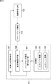
符号化制御処理が開始されると、制御部101の符号化処理制御部183は、ステップS301において、画像データを入力系111(例えばキャッシュメモリ143)から読み出し、画像符号化部112に入力させる。
When the encoding control process is started, the encoding
ステップS302において、符号化処理制御部183は、画像符号化部112を制御し、入力させた画像データを符号化する画像符号化処理を実行させる。ステップS303において、負荷情報取得部184は、その符号化処理についてスループット情報193を取得する。
In step S302, the encoding
ステップS304において、ハードウェア資源割り当て部461は、入力レートまたは出力レートのうち、少なくともいずれか一方に基づいて、画像符号化処理の一部または全部にハードウェア資源を割り当てる。この時、例えば符号化方法がJPEG2000の場合、符号化処理全体に割り当てるハードウェア資源を制御するようにしても良いし、EBCOT221により行われるエントロピ符号化処理に割り当てるハードウェア資源を制御するようにしてもよい。
In step S304, the hardware
ステップS305において、符号化処理制御部183は、画像符号化処理により生成されたコードストリームを出力系113に出力し、処理させる。
In step S305, the encoding
ステップS306において、符号化処理制御部183は、符号化制御処理を終了するか否かを判定する。例えば未処理の画像データが入力系111(例えばキャッシュメモリ143)に存在する等して、符号化制御処理を終了しないと判定された場合、ステップS301に処理が戻り、それ以降の処理が繰り返される。
In step S306, the encoding
ステップS306において、例えば未処理の画像データが入力系111(例えばキャッシュメモリ143)に存在せず、符号化制御処理を終了すると判定された場合、符号化制御処理が終了される。 In step S306, for example, when it is determined that the unprocessed image data does not exist in the input system 111 (for example, the cache memory 143) and the encoding control process is to be ended, the encoding control process is ended.
なお、ステップS303の処理(スループット情報の取得)は、その情報の内容に応じて適切なタイミングで行われる。したがって、例えば、ステップS302の処理より先にステップS303およびステップS304の処理が行われるようにしてもよい。また、例えば、画像符号化処理実行途中において、ステップS303およびステップS304の処理が行われるようにしてもよい。 Note that the process of step S303 (acquisition of throughput information) is performed at an appropriate timing according to the content of the information. Therefore, for example, the processing in step S303 and step S304 may be performed prior to the processing in step S302. Further, for example, the processing in step S303 and step S304 may be performed during the execution of the image encoding processing.
以上のような制御処理により、制御部101は、例えば、画像符号化処理のスループットが低すぎる場合、画像符号化処理に割り当てるハードウェア資源(例えばコア数)を増やすことにより、スループットを向上させることができる。また、例えば、画像符号化処理のスループットが高すぎる場合、制御部101は、画像符号化処理に割り当てるハードウェア資源(例えばコア数)を減らすことにより、スループットを低減させることができる。
Through the control process as described above, for example, when the throughput of the image encoding process is too low, the
このように、制御部101は、入力レートや出力レート等に基づいて、画像符号化処理に割り当てるハードウェア資源の量をより適切な状態に保つことができる。画像符号化処理に割り当てられないコアは、例えば他の処理に割り当てることができるので、以上のような制御により、サブCPUコア442がより有効に活用されるようになる。つまり、符号化装置100は、符号化処理においてハードウェア資源をより有効に活用することができる。
As described above, the
なお、画像符号化処理に割り当てるCPUの数を制御する場合や、画像符号化処理に割り当てるスレッド数を制御する場合も、基本的にコア数を制御する場合と同様に制御される。 In addition, when controlling the number of CPUs allocated to the image encoding process and when controlling the number of threads allocated to the image encoding process, the control is basically performed in the same manner as when the number of cores is controlled.
<4.第4の実施の形態>
[制御部の構成]
なお、以上に説明した負荷量の制御に関する情報は、復号処理の際に、ハードウェア資源の割り当て制御に利用することができる。この情報としては、例えば、画像符号化処理の圧縮率、画像符号化処理のスループット、画像符号化処理に割り当てたコア数、または、それらを変更したときの入力レートや出力レート等のシステム環境条件等がある。もちろん、これら以外の情報であっても良い。
<4. Fourth Embodiment>
[Configuration of control unit]
It should be noted that the information related to the load amount control described above can be used for hardware resource allocation control in the decoding process. This information includes, for example, the compression rate of the image encoding process, the throughput of the image encoding process, the number of cores assigned to the image encoding process, or system environment conditions such as the input rate and output rate when these are changed Etc. Of course, information other than these may be used.
図18は、この場合の制御部の主な構成例を示すブロック図である。図18に示されるように、この場合、制御部101は、基本的に図16を参照して説明した場合と同様の構成を有するが、さらに情報付加部471を有する。
FIG. 18 is a block diagram illustrating a main configuration example of the control unit in this case. As shown in FIG. 18, in this case, the
情報付加部471は、例えば、画像符号化処理の圧縮率、画像符号化処理のスループット、画像符号化処理に割り当てたコア数、または、それらを変更したときの入力レートや出力レート等のシステム環境条件等の負荷量の制御に関する情報を、負荷制御情報として、画像符号化処理により生成されたコードストリームのヘッダに負荷する。情報付加部471は、例えば、コードストリームのメインヘッダに付加する。
The
図19は、符号化方式がJPEG2000の場合のコードストリームのメインヘッダの例を説明する模式図である。図19に示されるように、符号化方式がJPEG2000の場合、コードストリームのメインヘッダ480には、SOC481に続いてSIZ482が形成される。SIZ482には、COD483、COC484、QCD485、QCC486、RGN487、POC488、およびCOM489等のマーカセグメントが形成される。
FIG. 19 is a schematic diagram illustrating an example of a main header of a code stream when the encoding method is JPEG2000. As shown in FIG. 19, when the encoding method is JPEG2000,
JPEG2000においては、COM489のシンタックスは、図20に示されるように定められており、COM491、Lcom492、およびRcom493等のマーカが含まれる。Rcom493は、16ビットのパラメータであり、値「0」と「1」は予約されているが、それ以外の値は更改されており、自由に使用することができる。
In JPEG2000, the syntax of COM489 is determined as shown in FIG. 20 and includes markers such as COM491, Lcom492, and Rcom493.
情報付加部471は、このRcom493に、「0」と「1」以外の値を用いて、圧縮率等の付加制御情報を付加する。つまり、値「2」から値「65,535」まの値を定義可能なので、例えば、圧縮率=3分の2=0.6667 x65,535=43,690とすれば良い。
The
[処理の流れ]
この場合の符号化制御処理の流れの例を図21のフローチャートを参照して説明する。
[Process flow]
An example of the flow of the encoding control process in this case will be described with reference to the flowchart of FIG.
符号化制御処理が開始されると、符号化処理制御部183は、ステップS401において、画像データを入力系111(例えばキャッシュメモリ143)から読み出し、画像符号化部112に入力させる。
When the encoding control process is started, the encoding
ステップS402において、符号化処理制御部183は、画像符号化部112を制御し、入力させた画像データを符号化する画像符号化処理を実行させる。ステップS403において、負荷情報取得部184は、その符号化処理についてスループット情報193を取得する。
In step S402, the encoding
ステップS404において、ハードウェア資源割り当て部461は、入力レートまたは出力レートのうち、少なくともいずれか一方に基づいて、画像符号化処理の一部または全部にハードウェア資源を割り当てる。この時、例えば符号化方法がJPEG2000の場合、符号化処理全体に割り当てるハードウェア資源を制御するようにしても良いし、EBCOT221により行われるエントロピ符号化処理に割り当てるハードウェア資源を制御するようにしてもよい。
In step S404, the hardware
ステップS405において、情報負荷部471は、例えば画像符号化処理の圧縮率等の、負荷制御情報をコードストリームのヘッダに登録する。
In step S405, the
ステップS406において、符号化処理制御部183は、画像符号化処理により生成されたコードストリームを出力系113に出力し、処理させる。
In step S406, the encoding
ステップS407において、符号化処理制御部183は、符号化制御処理を終了するか否かを判定する。例えば未処理の画像データが入力系111(例えばキャッシュメモリ143)に存在する等して、符号化制御処理を終了しないと判定された場合、ステップS401に処理が戻り、それ以降の処理が繰り返される。
In step S407, the encoding
ステップS407において、例えば未処理の画像データが入力系111(例えばキャッシュメモリ143)に存在せず、符号化制御処理を終了すると判定された場合、符号化制御処理が終了される。 If it is determined in step S407 that, for example, unprocessed image data does not exist in the input system 111 (for example, the cache memory 143) and the encoding control process is to be ended, the encoding control process is ended.
なお、ステップS403の処理(スループット情報の取得)は、その情報の内容に応じて適切なタイミングで行われる。したがって、例えば、ステップS402の処理より先にステップS403およびステップS404の処理が行われるようにしてもよい。また、例えば、画像符号化処理実行途中において、ステップS403およびステップS404の処理が行われるようにしてもよい。 Note that the processing of S403 (acquisition of throughput information) is performed at an appropriate timing according to the content of the information. Therefore, for example, the processing of step S403 and step S404 may be performed prior to the processing of step S402. In addition, for example, the processes in steps S403 and S404 may be performed during the execution of the image encoding process.
以上のような制御処理により、制御部101は、例えば、画像の圧縮率、画像符号化処理に割り当てられたコア数、または、スループットを変更したときのシステム環境情報(変更条件の履歴情報)等を含む負荷制御情報を、復号装置に提供することができる。
Through the control processing as described above, the
<5.第5の実施の形態>
[復号装置の構成]
以上のような負荷制御は復号処理においても適用可能である。
<5. Fifth embodiment>
[Configuration of Decoding Device]
The load control as described above can also be applied in the decoding process.
図22は、復号装置の主な構成例を示すブロック図である。 FIG. 22 is a block diagram illustrating a main configuration example of a decoding device.
図22に示される復号装置600は、符号化装置100の画像符号化処理に対応する方法で画像復号処理を行い、符号化装置100が生成したコードストリームを復号して画像データを得る装置である。復号装置600は、制御部601、入力系611、画像復号部612、および出力系613を有する。
A decoding device 600 shown in FIG. 22 is a device that performs image decoding processing by a method corresponding to the image encoding processing of the
制御部601は、入力系611乃至出力系613を制御し、画像データの復号に関する処理を実行させる。
The
入力系611は、入力系111と同様に、任意のハードウェア資源により実現される1つまたは複数の処理部よりなる系である。入力系611は、制御部601により制御され、復号処理の対象となるコードストリームに対して、例えば、記憶媒体からコードストリームを読み出したり、ネットワークを介して他の装置より送信されたコードストリームを受信したりする等、任意の処理を行う。また、入力系611は、制御部601により制御され、矢印621に示されるように、任意の処理を施したその画像データを画像復号部612に供給する。
Similar to the
画像復号部612は、制御部601により制御され、矢印621に示されるように、入力系611より供給されるコードストリームを取得する。また、画像復号部612は、制御部601により制御され、取得したコードストリームを所定の方式で復号して画像データを生成する。さらに、画像復号部612は、制御部601により制御され、矢印622に示されるように、生成した画像データを出力系613に供給する。
The
出力系613は、出力系113と同様に、任意のハードウェア資源により実現される1つまたは複数の処理部よりなる系である。出力系613は、制御部601により制御され、矢印622に示されるように、画像復号部612より供給される画像データを取得する。また、出力系613は、制御部601により制御され、取得したコードストリームに対して、例えば記憶媒体に記憶したり、ネットワークを介して他の装置に送信したりする等、任意の処理を行う。
Similar to the
制御部601は、矢印631に示されるように、入力系611から、入力系611が行う処理の処理速度を示す入力レート情報を取得する。同様に、制御部601は、矢印632に示されるように、出力系613から、出力系613が行う処理の処理速度を示す出力レート情報を取得する。さらに、制御部601は、矢印633に示されるように、画像復号部612から、画像復号部612が行う画像復号処理の負荷量を示す負荷情報633を取得する。
The
また、制御部601は、矢印634に示されるように入力系611に制御情報を供給して入力系611の処理を制御する。さらに、制御部601は、矢印635に示されるように画像復号部612に制御情報を供給して画像復号処理を制御する。また、制御部601は、矢印636に示されるように出力系613に制御情報を供給して出力系613の処理を制御する。
In addition, the
このとき、制御部601は、入力レート情報、出力レート情報、および負荷情報に基づいて、画像復号部612が行う画像復号処理の処理速度を決定する。
At this time, the
なお、復号装置600の場合、負荷情報は、画像復号部612により行われる画像復号処理の、予測される負荷の大きさを示す予測情報である。基本的に符号化装置100の場合と同様の情報である。
In the case of the decoding device 600, the load information is prediction information indicating the size of the load predicted for the image decoding processing performed by the
制御部601は、負荷情報より求められる画像復号処理の処理速度を、入力系611の処理の処理速度や、出力系613の処理の処理速度と比較し、それらの比較結果に基づいて画像復号処理の処理速度を制御する。
The
例えば、制御部601は、画像復号処理の処理速度が入力系611の処理の処理速度より遅い場合、画像復号処理の処理速度を入力系611の処理速度まで上昇させる。また、例えば、制御部601は、画像復号処理の処理速度が入力系611の処理の処理速度より速い場合、画像復号処理の処理速度を入力系611の処理速度まで低下させる。さらに、例えば、制御部601は、画像復号処理の処理速度が出力系613の処理の処理速度より速い場合、画像復号処理の処理速度を出力系613の処理速度まで低下させる。
For example, when the processing speed of the image decoding process is slower than the processing speed of the
このように、制御部601は、入力系611や出力系613等、画像復号部612の前段や後段の処理部が行う処理の処理速度も考慮して画像復号処理の処理速度を決定するので、復号装置600全体の処理速度を向上させるように画像復号処理の処理速度を制御することができる。
In this way, the
このような制御により復号装置600は、不要な負荷の増大を抑制するように、復号処理にハードウェア資源を割り当てることができる。つまり、復号装置600は、復号処理においてハードウェア資源をより有効に活用することができる。 With such control, the decoding device 600 can allocate hardware resources to the decoding process so as to suppress an increase in unnecessary load. That is, the decoding device 600 can more effectively utilize hardware resources in the decoding process.
次に、このような復号装置600の構成の具体的な例について説明する。 Next, a specific example of the configuration of such a decoding device 600 will be described.
図23は、図22の復号装置の具体的な例を示す図である。復号装置600Aは、図22の復号装置600の構成の具体的な一例を示す。図23に示されるように、復号装置600Aは、制御部601と画像復号部612がバス641に接続される。バス641には、さらに、入出力インタフェース641、キャッシュメモリ643、および記憶部644が接続される。
FIG. 23 is a diagram illustrating a specific example of the decoding device of FIG. Decoding
バス641は、バス141と同様の伝送媒体であり、例えばPCIバス等により構成される。入出力インタフェース642は、入出力インタフェース144と同様の、外部のネットワーク651と接続される通信インタフェースであり、例えば、HDMI、HD-SDI、Ethernet(登録商標)(LANボード)等により構成される。
The
キャッシュメモリ643は、キャッシュメモリ143と同様の記憶媒体であり、例えばRAM等の、記憶部644の読み出し速度や、入出力インタフェースの642のスループットに比べて高速にデータの授受が可能な半導体メモリにより構成される。記憶部644は、記憶部142と同様の記憶媒体であり、例えば、ハードディスクやフラッシュメモリ等により構成される。
The
このような構成の復号装置600Aにおいて、復号対象のコードストリームは例えば、ネットワーク651を介して他の装置より供給される。制御部601は、点線矢印661に示されるように、入出力インタフェース642を制御して、そのコードストリームを取得し、バス641を介してキャッシュメモリ643に供給させ、キャッシュメモリ643にそのコードストリームを保持させる。
In the
制御部601は、また、点線矢印662に示されるように、キャッシュメモリ643に保持されているコードストリームを読み出し、バス641を介して画像復号部612に供給させ、復号させる。
The
制御部601は、さらに、点線663に示されるように、コードストリームが符号化された画像データを、バス141を介して記憶部644に供給させ、記憶させる。
Further, as indicated by a dotted
つまり、この復号装置600Aにおいては、一点鎖線で示されるように、バス641、入出力インタフェース642、およびキャッシュメモリ643により入力系611が形成され、二点鎖線で示されるように、バス641および記憶部644により出力系613が形成される。
That is, in this
入力系611において、一般的に、入出力インタフェース642のデータの入出力レート(スループット)は、バス641の伝送レートやキャッシュメモリ143のデータ入出力レートより低い。従って、図22を参照して説明したように、制御部601は、画像復号部612の画像復号処理の処理速度(スループット)が入出力インタフェース642のデータの入出力速度より速い場合、画像復号部612の画像復号処理の処理速度を減速させ、画像復号部612の画像復号処理の処理速度(スループット)が入出力インタフェース642のデータの入出力速度より遅い場合、画像復号部612の画像復号処理の処理速度を加速させ、入出力インタフェース642のデータの入出力速度(入力系611の処理速度)に合わせる。
In the
また、出力系613において、一般的に、記憶部644へのデータの書き込みレートは、バス641の伝送レートより低い。従って、図22を参照して説明したように、制御部601は、画像復号部612の画像復号処理の処理速度(スループット)が記憶部642のデータ書き込み速度より速い場合、画像復号部612の画像復号処理の処理速度を減速させ、記憶部142のデータ書き込み速度(入力系611の処理速度)に合わせる。
In the
このように制御部601が復号処理を制御することにより、復号装置600Aは、各部の処理速度を適切に調整し、不要な待機時間の発生を抑制することができる。すなわち、復号装置600Aは、ハードウェア資源をより有効に利用して復号処理を行うことができる。
As described above, when the
図24は、図22の復号装置600の他の具体的な例を示す図である。 FIG. 24 is a diagram illustrating another specific example of the decoding device 600 of FIG.
復号装置600Bは、図22の復号装置600の構成の、他の具体的な一例を示す。図24に示されるように、復号装置600Bは、制御部601と画像復号部612がバス641に接続される。バス641には、さらに、キャッシュメモリ643、および入出力インタフェース642が接続される。
Decoding
このような構成の復号装置600Bにおいて、復号対象のコードストリームはネットワーク651を介して他の装置より供給される。制御部601は、点線矢印671に示されるように、入出力インタフェース642を制御して、そのコードストリームを取得し、バス641を介してキャッシュメモリ643に供給させ、キャッシュメモリ643にそのコードストリームを保持させる。
In the
制御部601は、また、点線矢印672に示されるように、キャッシュメモリ643に保持されているコードストリームを読み出し、バス141を介して画像復号部612に供給させ、復号させる。
Further, as indicated by a
制御部601は、さらに、点線673に示されるように、コードストリームが復号された画像データを、バス641を介して入出力インタフェース642に供給させ、入出力インタフェース642から外部のネットワーク651に出力させる。
Further, as indicated by a dotted
つまり、この復号装置600Bにおいては、一点鎖線で示されるように、バス641、キャッシュメモリ643、および入出力インタフェース642により入力系611が形成され、二点鎖線で示されるように、バス641および入出力インタフェース642により出力系613が形成される。
That is, in this
入力系611において、一般的に、入出力インタフェース642のデータの入出力レート(スループット)は、バス641の伝送レートやキャッシュメモリ643のデータ入出力レートより低い。従って、図22を参照して説明したように、制御部601は、画像復号部612の画像復号処理の処理速度(スループット)が入出力インタフェース642のデータの入出力速度より遅い場合、画像復号部612の画像復号処理の処理速度を加速させ、画像復号部612の画像復号処理の処理速度(スループット)が入出力インタフェース642のデータの入出力速度より速い場合、画像復号部612の画像復号処理の処理速度を減速させ、入出力インタフェース642のデータ入出力速度(入力系611の処理速度)に合わせる。
In the
また、出力系613において、図23の場合と同様に、制御部601は、画像復号部612の画像復号処理の処理速度(スループット)が入出力インタフェース642のデータの入出力速度より速い場合、画像復号部612の画像復号処理の処理速度を減速させ、入出力インタフェース642のデータ入出力速度(出力系613の処理速度)に合わせる。
In the
このように制御部601が復号処理を制御することにより、復号装置600Bは、各部の処理速度を適切に調整し、不要な待機時間の発生を抑制することができる。すなわち、復号装置600Bは、ハードウェア資源をより有効に利用して復号処理を行うことができる。
As described above, when the
次に、このような制御を行う制御部601について説明する。図25は、制御部の主な構成例を示すブロック図である。図25に示されるように、制御部601は、入力レート情報取得部681、出力レート情報取得部682、復号処理制御部683、負荷情報取得部684、負荷制御部685、および記憶部686を有する。
Next, the
入力レート情報取得部681は、入力系611を構成するデバイスより、入力系611のスループットを示す入力レート情報691を取得し、それを記憶部686に記憶させる。出力レート情報取得部682は、出力系613を構成するデバイスより、出力系613のスループットを示す出力レート情報692を取得し、それを記憶部686に記憶させる。
The input rate information acquisition unit 681 acquires the
なお、この入力レート情報691および出力レート情報692は、入力系611または出力系613において計測された値であってもよいが、入力系611または出力系613を構成するデバイスの仕様であってもよい。したがって、入力系611および出力系613を構成するデバイスが予め定められており、それらのデバイスの仕様を入力レート情報691および出力レート情報692とする場合、入力レート情報691および出力レート情報692は、例えば工場出荷時等に予め記憶部686に記憶させておくようにしてもよい。その場合、入力レート情報取得部681および出力レート情報取得部682は、省略することができる。
The
復号処理制御部683は、画像復号部612による画像データの復号処理を制御する。復号処理制御部183は、負荷制御部685において決定された負荷量となるように、復号処理のスループットを制御する。
The decoding
負荷情報取得部684は、画像復号部612の画像復号処理の負荷の大きさ(負荷量)の予測値を示す負荷情報を取得する。例えば、負荷情報取得部684は、この負荷情報として、画像復号処理のスループットの予測値を直接的または間接的に示すスループット情報693を取得する。スループット情報693の内容は任意であるが、例えば、画像データの符号化の難易度を示す情報、過去の復号処理の単位時間当たりの処理量、またはコードストリームのファイルサイズ等により構成される。負荷情報取得部684は、取得した負荷情報を負荷制御部685に供給する。
The load
負荷制御部685は、記憶部686から入力レート情報691および出力レート情報692を読み出し、それらと、負荷情報取得部684から供給された負荷情報(スループット情報693)とに基づいて、画像復号部612による画像復号処理の負荷量を決定する。負荷制御部685は、復号処理制御部683を制御することにより、決定した負荷量となるように画像復号処理のスループットを制御する。
The
記憶部686は、例えばRAM等の半導体メモリにより構成される記憶媒体であり、入力レート情報691や出力レート情報692等の情報を記憶する。
The
[処理の流れ]
次に、以上のような復号装置600において実行される各種処理の流れについて説明する。最初に、制御部601による復号制御処理の流れの例を、図26のフローチャートを参照して説明する。
[Process flow]
Next, the flow of various processes executed in the decoding device 600 as described above will be described. First, an example of the flow of decoding control processing by the
復号制御処理が開始されると、制御部601の入力レート情報取得部681は、ステップS601において、入力レート情報を取得する。ステップS602において、出力レート情報取得部682は、出力レート情報を取得する。ステップS603において、復号処理制御部683は、コードストリームを入力系611(例えばキャッシュメモリ643)から読み出し、画像復号部612に入力させる。
When the decoding control process is started, the input rate information acquisition unit 681 of the
ステップS604において、復号処理制御部683は、画像復号部612を制御し、入力させた画像データを復号する画像復号処理を実行させる。ステップS605において、負荷情報取得部684は、その復号処理についてスループット情報693を取得する。
In step S604, the decoding
ステップS606において、負荷制御部685は、入力レートまたは出力レートのうち、少なくともいずれか一方に基づいて、ステップS604の制御によって実行された画像復号処理のスループットを制御する。
In step S606, the
ステップS607において、復号処理制御部683は、画像復号処理により生成された画像データを出力系613に出力し、処理させる。
In step S607, the decoding
ステップS608において、復号処理制御部683は、復号制御処理を終了するか否かを判定する。例えば未処理の画像データが入力系611(例えばキャッシュメモリ643)に存在する等して、復号制御処理を終了しないと判定された場合、ステップS601に処理が戻り、それ以降の処理が繰り返される。
In step S608, the decoding
このとき、入力レートが固定値の場合、ステップS601の処理は省略可能である。同様に、出力レートが固定値の場合、ステップS602の処理は省略可能である。 At this time, if the input rate is a fixed value, the process of step S601 can be omitted. Similarly, when the output rate is a fixed value, the process of step S602 can be omitted.
ステップS608において、例えば未処理の画像データが入力系611(例えばキャッシュメモリ643)に存在せず、復号制御処理を終了すると判定された場合、復号制御処理が終了される。 In step S608, for example, when it is determined that the unprocessed image data does not exist in the input system 611 (for example, the cache memory 643) and the decoding control process is to be ended, the decoding control process is ended.
なお、ステップS605の処理(スループット情報の取得)は、その情報の内容に応じて適切なタイミングで行われる。したがって、例えば、ステップS604の処理より先にステップS605およびステップS606の処理が行われるようにしてもよい。また、例えば、画像復号処理実行途中において、ステップS605およびステップS606の処理が行われるようにしてもよい。 Note that the processing of step S605 (acquisition of throughput information) is performed at an appropriate timing according to the content of the information. Therefore, for example, the processing of step S605 and step S606 may be performed prior to the processing of step S604. In addition, for example, the processing of step S605 and step S606 may be performed during the execution of the image decoding processing.
次に、図26のステップS606において実行される負荷制御処理の詳細な流れの例について、図27のフローチャートを参照して説明する。 Next, an example of a detailed flow of the load control process executed in step S606 of FIG. 26 will be described with reference to the flowchart of FIG.
負荷制御処理が開始されると、負荷制御部685は、ステップS621において、入力レート情報691およびスループット情報693に基づいて、復号処理のスループットが入力レートより低いか否かを判定する。
When the load control process is started, the
復号処理のスループットが入力レートより低いと判定された場合、処理はステップS622に進む。この場合、画像復号処理の処理速度が遅すぎて、入力系611における処理がオーバフローする恐れがある。つまり、画像復号処理のハードウェア資源の消費量が少なすぎる。ハードウェア資源に余裕があるのであれば、さらに画像復号処理がハードウェア資源を消費するようにすることにより、入力系611におけるオーバフローの発生を抑制し、復号装置600のスループットを向上させることができる。そこで、負荷制御部685は、ステップS622において、画像復号部612の画像復号処理の処理速度を加速させ、画像復号処理のスループットを入力レートまで上昇させる。ステップS622の処理が終了すると、図26のステップS606に戻り、それ以降の処理が実行される。
If it is determined that the throughput of the decoding process is lower than the input rate, the process proceeds to step S622. In this case, there is a possibility that the processing speed of the image decoding process is too slow and the process in the
復号処理のスループットが入力レートより低くないと判定された場合、処理はステップS623に進む。負荷制御部685は、ステップS623において、入力レート情報691およびスループット情報693に基づいて、復号処理のスループットが入力レートより高いか否かを判定する。
If it is determined that the throughput of the decoding process is not lower than the input rate, the process proceeds to step S623. In step S623, the
復号処理のスループットが入力レートより高いと判定された場合、処理はステップS624に進む。この場合、画像復号処理の処理速度が速すぎて、入力系611からのコードストリームの供給が追いつかない。つまり、画像復号処理がハードウェア資源を不要に消費している。そこで、負荷制御部685は、ステップS624において、画像復号部612の画像復号処理の処理速度を減速させ、画像復号処理のスループットを入力レートまで低下させる。ステップS624の処理が終了すると、図26のステップS606に戻り、それ以降の処理が実行される。
If it is determined that the throughput of the decoding process is higher than the input rate, the process proceeds to step S624. In this case, the processing speed of the image decoding process is too fast, and the supply of the code stream from the
復号処理のスループットが入力レートより高くないと判定された場合、処理はステップS625に進む。負荷制御部685は、ステップS625において、出力レート情報692およびスループット情報693に基づいて、復号処理のスループットが出力レートより高いか否かを判定する。
If it is determined that the throughput of the decoding process is not higher than the input rate, the process proceeds to step S625. In step S625, the
復号処理のスループットが出力レートより高いと判定された場合、処理はステップS626に進む。この場合、画像復号処理の処理速度が速すぎて、出力系613における処理がオーバフローする恐れがある。つまり、画像復号処理がハードウェア資源を不要に消費している。そこで、負荷制御部685は、ステップS626において、画像復号部612の画像復号処理の処理速度を減速させ、画像復号処理のスループットを出力レートまで低下させる。ステップS626の処理が終了すると、図26のステップS606に戻り、それ以降の処理が実行される。
If it is determined that the throughput of the decoding process is higher than the output rate, the process proceeds to step S626. In this case, there is a possibility that the processing speed of the image decoding process is too fast and the process in the
復号処理のスループットが出力レートより高くないと判定された場合、負荷制御処理が終了され、図26のステップS606に戻り、それ以降の処理が実行される。 When it is determined that the throughput of the decoding process is not higher than the output rate, the load control process is terminated, the process returns to step S606 in FIG. 26, and the subsequent processes are executed.
以上のような制御処理が行われることにより、復号装置600は、復号処理においてハードウェア資源をより有効に活用することができる。 By performing the control process as described above, the decoding apparatus 600 can more effectively utilize hardware resources in the decoding process.
なお、図27においては、ステップS621、ステップS623、またはステップS625の各判定処理を、図27に示されるフローチャートの順に行うように説明したが、各判定条件の優先順位は任意であり、どの判定から行うようにしてもよい。また、複数の判定を満たすときのみ復号処理のスループットの制御(例えば、ステップS622、ステップS624、またはステップS626)を行うようにしてもよい。 In FIG. 27, it has been described that each determination process of step S621, step S623, or step S625 is performed in the order of the flowchart shown in FIG. 27. However, the priority of each determination condition is arbitrary, and which determination You may make it perform from. Further, the throughput of the decoding process (for example, step S622, step S624, or step S626) may be performed only when a plurality of determinations are satisfied.
<6.第6の実施の形態>
[画像復号部の構成]
上述したように、符号化方式は任意である。つまり、画像復号部612が行う画像複合処理の復号方法は任意である。以下に符号化方式がJPEG2000の場合について説明する。図28は、画像復号部612の主な構成例を示すブロック図である。図28に示されるように、画像復号部612は、パケット解読部701、算術復号部702、ビットモデリング部703、ビットプレーン合成部704、コードブロック合成部705、ウェーブレット逆変換部706、およびDCレベル逆シフト部707を有する。
<6. Sixth Embodiment>
[Configuration of image decoding unit]
As described above, the encoding method is arbitrary. That is, the decoding method of the image composite process performed by the
パケット解読部701は、矢印731に示されるように、符号化装置100より供給されるパケットを解読し、矢印732に示されるように、コードストリームを算術復号部702に供給する。また、パケット解読部701は、コードストリームのパケットを解読し、コードストリームのファイルサイズを抽出し、矢印721に示されるように、負荷情報として負荷情報取得部684に供給する。
The
算術復号部702およびビットモデリング部703は、EBCOT部711として動作し、入力されるコードストリームに対して、JPEG2000規格で定められたEBCOTと呼ばれるエントロピ復号を行う。
The
算術復号部702は、算術符号化部207に対応する方法でコードストリームを復号し、矢印733に示されるように、コンテキストをビットモデリング部703に供給する。ビットモデリング部703は、ビットモデリング部206に対応する方法で、ビットプレーンに展開されたウェーブレット係数を生成する。ビットモデリング部703は、生成したビットプレーン毎の係数データを、矢印734に示されるように、ビットプレーン合成部704に供給する。
The
ビットプレーン合成部704は、ビットプレーンに展開されたウェーブレット係数を合成する。ビットプレーン合成部704は、ビットプレーンを合成したウェーブレット係数を、矢印735に示されるように、コードブロック合成部705に供給する。
The bit
コードブロック合成部705は、供給されたビットプレーンを用いてコードブロック単位の係数データを生成し、さらにそれらを合成し、サブバンド毎の係数データを生成する。コードブロック合成部705は、矢印736に示されるように、それをウェーブレット逆変換部706に供給する。
The code
ウェーブレット逆変換部706は、供給されたウェーブレット係数をウェーブレット逆変換し、ベースバンドの画像データを生成する。ウェーブレット逆変換部706は、生成したベースバンドの画像データを、矢印737に示されるように、DCレベル逆シフト部707に供給する。
The wavelet
DCレベル逆シフト部707は、その画像データのDC成分に対して、DCレベルシフト部201においてシフトした分を元に戻すDCレベル逆シフト処理を必要に応じて行う。DCレベル逆シフト部707は、DCレベル逆シフト処理後の画像データを、矢印738に示されるように、画像復号部612の外部(出力系613)に出力する。
The DC level
[制御部の構成]
次に、このような画像復号部612を制御する制御部について説明する。図29は、制御部の主な構成例を示すブロック図である。図29において、制御部601は、基本的に図25を参照して説明した場合と同様の構成を有する。すなわち、制御部601は、復号処理制御部683乃至記憶部686を有する。
[Configuration of control unit]
Next, a control unit that controls the
ただし、この場合、制御部601の負荷情報取得部684は、負荷情報として、画像復号部612のパケット解読部701からコードストリームのファイルサイズ751を取得する。復号処理の難易度は、復号処理対象のコードストリームのファイルサイズの大きさにおおよそ比例する。つまり、ファイルサイズが大きいほど、復号処理の難易度は上がり、復号処理の負荷量は増大することが予想される。
In this case, however, the load
記憶部686には、入力レート情報691や出力レート情報692の代わりに、テーブル情報752が記憶されている。テーブル情報752は、ファイルサイズ751から画像復号処理の処理速度の制御量を決定するためのテーブル情報である。このテーブル情報752において、コードストリームのファイルサイズの大きさと画像復号処理の処理速度の制御量との対応関係は、入力レートと出力レートを考慮して作成されている。
The
負荷制御部685は、記憶部686より読み出したテーブル情報752を用いて、負荷情報取得部684により取得されたファイルサイズ751の値に対応する画像復号処理の処理速度の制御量を求め、復号処理制御部683を制御する。このようにすることにより、負荷制御685は、入力レート、出力レート、および負荷情報に基づいて、画像復号処理の負荷量を制御することになる。
The
したがって、上述した場合と同様に、復号装置600は、復号処理においてハードウェア資源をより有効に活用することができる。 Therefore, as in the case described above, the decoding device 600 can more effectively utilize hardware resources in the decoding process.
なお、この場合、図25の入力レート情報取得部681および出力レート情報取得部682は、省略される。 In this case, the input rate information acquisition unit 681 and the output rate information acquisition unit 682 in FIG. 25 are omitted.
[処理の流れ]
次にこの場合の復号制御処理の流れの例を図30のフローチャートを参照して説明する。
[Process flow]
Next, an example of the flow of the decoding control process in this case will be described with reference to the flowchart of FIG.
復号制御処理が開始されると、負荷情報取得部684は、ステップS701において、パケット解読部701を制御し、処理対象のコードストリームのファイルサイズ751を取得する。ステップS702において、負荷制御部685は、取得されたファイルサイズ751と、テーブル情報752に基づいて、スループットを制御する。
When the decoding control process is started, the load
ステップS703において、復号処理制御部683は、入力系611(例えばキャッシュメモリ643)からコードストリームを画像復号部612に入力させる。
In step S703, the decoding
ステップS704において、復号処理制御部683は、EBCOT部711等を制御し、負荷制御部685により決定されたスループットでエントロピ復号を行わせる。
In step S704, the decoding
ステップS705において、復号処理制御部683は、ビットプレーン合成部704を制御し、復号処理により生成された係数データのビットプレーンを合成させる。ステップS706において、復号処理制御部683は、コードブロック合成部705を制御し、係数データのコードブロックを合成させ、サブバンド毎の係数データを生成させる。
In step S705, the decoding
ステップS707において、復号処理制御部683は、ウェーブレット逆変換部706を制御し、サブバンド毎の係数データをウェーブレット逆変換させ、ベースバンドの画像データを生成する。ステップS708において、復号処理制御部683は、DCレベル逆シフト部707を制御し、画像データのDCレベルを逆シフトさせる。復号処理制御部683は、ステップS709において、DCレベル逆シフト部707を制御し、処理済の画像データを出力系613に出力させる。
In step S707, the decoding
ステップS710において、復号処理制御部683は、復号制御処理を終了するか否かを判定する。終了しないと判定された場合、ステップS701に戻り、それ以降の処理が繰り返される。また、ステップS710において、復号制御処理を終了すると判定された場合、復号制御処理が終了される。
In step S710, the decoding
このように制御が行われることにより、復号装置600は、復号処理においてハードウェア資源をより有効に活用することができる。また、復号装置600は、コードストリームのファイルサイズに基づいてこのような負荷制御を行うことができるので、容易に、ハードウェア資源をより有効に活用することができる。 By performing control in this way, the decoding device 600 can more effectively utilize hardware resources in the decoding process. Also, since the decoding apparatus 600 can perform such load control based on the file size of the code stream, it can easily utilize hardware resources more effectively.
なお、制御部601は、コードストリームのファイルサイズの代わりに、コードストリームの例えばメインヘッダ等に付加される負荷制御情報に基づいて、画像復号処理のスループット制御を行うようにしてもよい。この負荷制御情報は、上述したように、例えば、画像データの圧縮率、画像符号化処理時に割り当てられたハードウェア資源(コア数等)、または、スループットを制御したときのシステム環境情報(変更条件履歴情報)等により構成される。
Note that the
いずれの場合においても、記憶部686に、負荷制御情報に対応するテーブル情報が予め用意されており、負荷制御部685は、そのテーブル情報を用いて、取得された負荷制御情報の値に対応する制御量を求める。
In any case, table information corresponding to the load control information is prepared in advance in the
このようにすることにより、復号装置600は、容易に、ハードウェア資源をより有効に活用することができる。 By doing in this way, the decoding apparatus 600 can utilize a hardware resource more effectively easily.
以上における画像復号処理のスループットの制御方法は任意である。例えば、画像復号処理のクロックの速度を変更するようにしてもよいし、画像復号処理の実行に割り当てる時間を増減させても良いし、復号方法を変更するようにしてもよい。 The method for controlling the throughput of the image decoding process described above is arbitrary. For example, the clock speed of the image decoding process may be changed, the time allocated to the execution of the image decoding process may be increased or decreased, and the decoding method may be changed.
また、例えば、画像復号部612の画像復号処理をソフトウェアにより実現させるようにしてもよく、その場合、制御部601が、画像復号処理に割り当てるハードウェア資源の量を増減させることにより、画像復号処理のスループットを制御するようにしてもよい。例えば、複数のCPU、複数のコアを有するCPU、またはマルチスレッド対応のCPUを用いて画像復号処理を実行させる場合、制御部601は、画像復号処理に割り当てるCPU数、コア数、またはスレッド数を増減させることにより、画像復号処理のスループットを制御するようにしてもよい。
Further, for example, the image decoding process of the
<7.第7の実施の形態>
[制御部の構成]
以下に、複数コアを有するCPUを用いて画像復号処理を行う場合のハードウェア資源割り当て方法の様子について説明する。
<7. Seventh Embodiment>
[Configuration of control unit]
Hereinafter, a situation of a hardware resource allocation method when performing image decoding processing using a CPU having a plurality of cores will be described.
図31は、図15に示されるような、複数コアのCPUを有するハードウェア資源を用いて画像復号処理を実行する場合の、制御部の主な構成例を示すブロック図である。 FIG. 31 is a block diagram illustrating a main configuration example of the control unit in a case where image decoding processing is executed using hardware resources having a multi-core CPU as illustrated in FIG. 15.
この場合の制御部601の構成も、基本的に図25を参照して説明した場合と同様であるが、負荷制御部685の代わりに、ハードウェア資源割り当て部761を有する。ハードウェア資源割り当て部761は、入力レート情報691、出力レート情報692、およびスループット情報693に基づいて、画像復号処理に割り当てるハードウェア資源、すなわち、サブCPUコア442のコア数を制御する。復号処理制御部683は、ハードウェア資源割り当て部761により割り当てられたサブCPUコア442を用いて画像復号処理を行う。
The configuration of the
なお、ここでは、入力レート情報691および出力レート情報692が予め記憶部686に記憶されているものとし、入力レート情報取得部681および出力レート情報取得部682は省略されるものとする。もちろんこれらを有するようにしてもよい。
Here, it is assumed that the
[処理の流れ]
次に、この場合の復号制御処理の流れの例について、図32のフローチャートを参照して説明する。
[Process flow]
Next, an example of the flow of decoding control processing in this case will be described with reference to the flowchart of FIG.
復号制御処理が開始されると、制御部601の符号化処理制御部683は、ステップS731において、コードストリームを入力系611(例えばキャッシュメモリ643)から読み出し、画像復号部612に入力させる。
When the decoding control process is started, the encoding
ステップS732において、復号処理制御部683は、画像復号部612を制御し、入力させたコードストリームを復号する画像復号処理を実行させる。ステップS733において、負荷情報取得部684は、その復号処理についてスループット情報693を取得する。
In step S732, the decoding
ステップS734において、ハードウェア資源割り当て部761は、入力レートまたは出力レートのうち、少なくともいずれか一方に基づいて、画像復号処理の一部または全部にハードウェア資源を割り当てる。この時、例えば復号方法がJPEG2000の場合、復号処理全体に割り当てるハードウェア資源を制御するようにしても良いし、EBCOT部7111により行われるエントロピ復号処理に割り当てるハードウェア資源を制御するようにしてもよい。
In step S734, the hardware
ステップS735において、復号処理制御部683は、画像復号処理により生成された画像データを出力系613に出力し、処理させる。ステップS736において、復号処理制御部683は、復号制御処理を終了するか否かを判定する。例えば未処理のコードストリームが入力系611(例えばキャッシュメモリ643)に存在する等して、復号制御処理を終了しないと判定された場合、ステップS731に処理が戻り、それ以降の処理が繰り返される。
In step S735, the decoding
ステップS736において、例えば未処理のコードストリームが入力系611(例えばキャッシュメモリ643)に存在せず、復号制御処理を終了すると判定された場合、復号制御処理が終了される。 If it is determined in step S736 that, for example, an unprocessed code stream does not exist in the input system 611 (for example, the cache memory 643) and the decoding control process is to be ended, the decoding control process is ended.
なお、ステップS733の処理(スループット情報の取得)は、その情報の内容に応じて適切なタイミングで行われる。したがって、例えば、ステップS732の処理より先にステップS733およびステップS734の処理が行われるようにしてもよい。また、例えば、画像復号処理実行途中において、ステップS733およびステップS734の処理が行われるようにしてもよい。 Note that the processing of step S733 (acquisition of throughput information) is performed at an appropriate timing according to the content of the information. Therefore, for example, the processing of step S733 and step S734 may be performed prior to the processing of step S732. Further, for example, the processes in steps S733 and S734 may be performed during the execution of the image decoding process.
以上のような制御処理により、制御部601は、例えば、画像復号処理のスループットが低すぎる場合、画像復号処理に割り当てるハードウェア資源(例えばコア数)を増やすことにより、スループットを向上させることができる。また、例えば、画像復号処理のスループットが高すぎる場合、制御部601は、画像復号処理に割り当てるハードウェア資源(例えばコア数)を減らすことにより、スループットを低減させることができる。
By the control processing as described above, for example, when the throughput of the image decoding process is too low, the
このように、制御部601は、入力レートや出力レート等に基づいて、画像復号処理に割り当てるハードウェア資源の量をより適切な状態に保つことができる。画像復号処理に割り当てられないコアは、例えば他の処理に割り当てることができるので、以上のような制御により、サブCPUコア442がより有効に活用されるようになる。つまり、復号装置600は、画像復号処理においてハードウェア資源をより有効に活用することができる。
As described above, the
なお、画像復号処理に割り当てるCPUの数を制御する場合や、画像復号処理に割り当てるスレッド数を制御する場合も、基本的にコア数を制御する場合と同様に制御される。 In addition, when controlling the number of CPUs allocated to the image decoding process or when controlling the number of threads allocated to the image decoding process, the control is basically performed in the same manner as when the number of cores is controlled.
上述した一連の処理をソフトウェアにより実行させる場合には、そのソフトウェアを構成するプログラムが、ネットワークや記録媒体からインストールされる。この記録媒体は、例えば、図15に示されるように、装置本体とは別に、ユーザにプログラムを配信するために配布される、プログラムが記録されている磁気ディスク(フレキシブルディスクを含む)、光ディスク(CD-ROM(Compact Disc - Read Only Memory),DVD(Digital Versatile Disc)を含む)、光磁気ディスク(MD(Mini Disc)を含む)、もしくは半導体メモリなどよりなるリムーバブルメディア311により構成されるだけでなく、装置本体に予め組み込まれた状態でユーザに配信される、プログラムが記録されているHDD405や記憶装置303に含まれるハードディスクやメモリなどで構成される。
When the above-described series of processing is executed by software, a program constituting the software is installed from a network or a recording medium. For example, as shown in FIG. 15, the recording medium is distributed to distribute the program to the user separately from the apparatus main body, and includes a magnetic disk (including a flexible disk) on which the program is recorded, an optical disk ( It is only composed of removable media 311 made of CD-ROM (compact disc-read only memory), DVD (including digital versatile disc), magneto-optical disc (including MD (mini disc)), or semiconductor memory. Rather, it is composed of an
なお、本明細書において、記録媒体に記録されるプログラムを記述するステップは、記載された順序に沿って時系列的に行われる処理はもちろん、必ずしも時系列的に処理されなくとも、並列的あるいは個別に実行される処理をも含むものである。 In the present specification, the step of describing the program recorded on the recording medium is not limited to the processing performed in chronological order according to the described order, but is not necessarily performed in chronological order. It also includes processes that are executed individually.
もちろん、上述した一連の処理は、汎用のハードウェアを用いてソフトウェアを実行することにより実現させることもできるが、専用のハードウェアにより実現させることもできる。 Of course, the above-described series of processing can be realized by executing software using general-purpose hardware, but can also be realized by dedicated hardware.
また、本明細書において、システムとは、複数のデバイス(装置)により構成される装置全体を表すものである。 Further, in this specification, the system represents the entire apparatus composed of a plurality of devices (apparatuses).
なお、以上において、1つの装置(または処理部)として説明した構成を分割し、複数の装置(または処理部)として構成するようにしてもよい。逆に、以上において複数の装置(または処理部)として説明した構成をまとめて1つの装置(または処理部)として構成されるようにしてもよい。また、各装置(または処理部)の構成に上述した以外の構成を付加するようにしてももちろんよい。さらに、システム全体としての構成や動作が実質的に同じであれば、ある装置(または処理部)の構成の一部を他の装置(または処理部)の構成に含めるようにしてもよい。つまり、本発明の実施の形態は、上述した実施の形態に限定されるものではなく、本発明の要旨を逸脱しない範囲において種々の変更が可能である。 In the above, the configuration described as one device (or processing unit) may be divided and configured as a plurality of devices (or processing units). Conversely, the configurations described above as a plurality of devices (or processing units) may be combined into a single device (or processing unit). Of course, a configuration other than that described above may be added to the configuration of each device (or processing unit). Furthermore, if the configuration and operation of the entire system are substantially the same, a part of the configuration of a certain device (or processing unit) may be included in the configuration of another device (or processing unit). That is, the embodiment of the present invention is not limited to the above-described embodiment, and various modifications can be made without departing from the gist of the present invention.
100 符号化装置, 101 制御部, 111 入力系, 112 画像符号化部, 113 出力系, 183 符号化処理制御部, 184 負荷情報取得部, 185 負荷制御部, 191 スループット情報, 251 ゼロビットプレーン数, 252 テーブル情報, 461 ハードウェア資源割り当て部, 471 情報付加部, 600 復号装置, 601 制御部, 611 入力系, 612 画像復号部, 613 出力系, 683 復号処理制御部, 684 負荷情報取得部, 685 付加制御部, 693 スループット情報, 751 ファイルサイズ, 752 テーブル情報, 761 ハードウェア資源割り当て部 100 encoding device, 101 control unit, 111 input system, 112 image encoding unit, 113 output system, 183 encoding processing control unit, 184 load information acquisition unit, 185 load control unit, 191 throughput information, 251 number of zero bit planes , 252 table information, 461 hardware resource allocation unit, 471 information addition unit, 600 decoding device, 601 control unit, 611 input system, 612 image decoding unit, 613 output system, 683 decoding processing control unit, 684 load information acquisition unit, 685 Additional control unit, 693 Throughput information, 751 File size, 752 Table information, 761 Hardware resource allocation unit
Claims (17)
前記第1の処理手段により前記第1の処理が行われた前記画像データに対して前記符号化処理を行い、コードストリームを生成する符号化手段と、
前記符号化手段による前記符号化処理により前記画像データが符号化されて生成された前記コードストリームに対して、所定の第2の処理を行う第2の処理手段と、
前記第1の処理手段による前記第1の処理の処理速度、および、前記第2の処理手段による前記第2の処理の処理速度に応じて、前記符号化手段による前記符号化処理の処理速度を制御する制御手段と
を備える符号化装置。 First processing means for performing a predetermined first process on the image data to be encoded before the encoding process;
Encoding means for performing the encoding process on the image data subjected to the first processing by the first processing means to generate a code stream;
Second processing means for performing predetermined second processing on the code stream generated by encoding the image data by the encoding processing by the encoding means;
According to the processing speed of the first processing by the first processing means and the processing speed of the second processing by the second processing means, the processing speed of the encoding processing by the encoding means is An encoding device comprising: control means for controlling.
請求項1に記載の符号化装置。 The encoding device according to claim 1, wherein the control means reduces the processing speed of the encoding process when the processing speed of the encoding process is faster than the processing speed of the first process.
請求項1に記載の符号化装置。 The encoding device according to claim 1, wherein the control means reduces the processing speed of the encoding process when the processing speed of the encoding process is faster than the processing speed of the second process.
請求項1に記載の符号化装置。 The encoding device according to claim 1, wherein the control means increases the processing speed of the encoding process when the processing speed of the encoding process is slower than the processing speed of the second process.
前記制御手段は、前記符号化処理に割り当てる前記コアの数を増減させることにより、前記符号化処理の処理速度を制御する
請求項1に記載の符号化装置。 The encoding means is realized by a processor having a plurality of cores,
The encoding apparatus according to claim 1, wherein the control unit controls the processing speed of the encoding process by increasing or decreasing the number of cores allocated to the encoding process.
請求項1に記載の符号化装置。 The encoding apparatus according to claim 1, wherein the encoding unit performs the encoding process by a lossless encoding method.
前記制御手段は、前記画像データのコードブロック毎のゼロビットプレーン数を取得し、前記ゼロビットプレーン数から有効ビットプレーン数のピクチャ毎の総和を算出し、前記有効ビットプレーン数のピクチャ毎の総和を用いて、前記符号化手段による前記符号化処理の処理速度を制御する
請求項1に記載の符号化装置。 The encoding means performs the encoding process by a lossless encoding method of JPEG2000 method,
The control means obtains the number of zero bit planes for each code block of the image data, calculates the sum of the number of effective bit planes for each picture from the number of zero bit planes, and sums the number of effective bit planes for each picture. The encoding apparatus according to claim 1, wherein a processing speed of the encoding process by the encoding unit is controlled using the encoding unit.
請求項1に記載の符号化装置。 The encoding apparatus according to claim 1, further comprising an adding unit that adds load control information related to control of a processing speed of the encoding process by the control unit to the code stream.
前記符号化装置の符号化手段が、前記第1の処理が行われた前記画像データに対して前記符号化処理を行い、コードストリームを生成し、
前記符号化装置の第2の処理手段が、前記符号化処理により前記画像データが符号化されて生成された前記コードストリームに対して、所定の第2の処理を行い、
前記符号化装置の制御手段が、前記第1の処理の処理速度および前記第2の処理の処理速度に応じて、前記符号化処理の処理速度を制御する
符号化方法。 The first processing means of the encoding device performs a predetermined first process on the image data to be encoded before the encoding process,
An encoding unit of the encoding device performs the encoding process on the image data on which the first process has been performed, and generates a code stream;
A second processing unit of the encoding device performs a predetermined second process on the code stream generated by encoding the image data by the encoding process;
An encoding method, wherein the control means of the encoding device controls the processing speed of the encoding process according to the processing speed of the first process and the processing speed of the second process.
前記第1の処理手段により前記第1の処理が行われた前記コードストリームに対して前記復号処理を行い、前記画像データを生成する復号手段と、
前記復号手段による前記復号処理により前記コードストリームが復号されて生成された前記画像データに対して、所定の第2の処理を行う第2の処理手段と、
前記第1の処理手段による前記第1の処理の処理速度、および、前記第2の処理手段による前記第2の処理の処理速度に応じて、前記復号手段による前記復号処理の処理速度を制御する制御手段と
を備える復号装置。 First processing means for performing a predetermined first process on the code stream generated by encoding image data, which is a target of the decoding process, before the decoding process;
Decoding means for generating the image data by performing the decoding process on the code stream on which the first processing has been performed by the first processing means;
Second processing means for performing predetermined second processing on the image data generated by decoding the codestream by the decoding processing by the decoding means;
The processing speed of the decoding process by the decoding means is controlled according to the processing speed of the first processing by the first processing means and the processing speed of the second processing by the second processing means. And a decoding device.
請求項10に記載の復号装置。 The decoding device according to claim 10, wherein the control means increases the processing speed of the decoding process when a processing speed of the decoding process is slower than a processing speed of the first process.
請求項10に記載の復号装置。 The decoding device according to claim 10, wherein the control unit decreases the processing speed of the decoding process when the processing speed of the decoding process is faster than the processing speed of the first process.
請求項10に記載の復号装置。 The decoding device according to claim 10, wherein when the processing speed of the decoding process is faster than the processing speed of the second process, the control unit decreases the processing speed of the decoding process.
前記制御手段は、前記復号処理に割り当てる前記コアの数を増減させることにより、前記復号処理の処理速度を制御する
請求項10に記載の復号装置。 The decoding means is realized by a processor having a plurality of cores,
The decoding device according to claim 10, wherein the control means controls the processing speed of the decoding process by increasing or decreasing the number of cores allocated to the decoding process.
請求項10に記載の復号装置。 The decoding device according to claim 10, wherein the decoding unit performs the decoding process by a JPEG2000 lossless decoding method.
請求項10に記載の復号装置。 The decoding device according to claim 10, wherein the control unit controls a processing speed of the decoding process performed by the decoding unit based on a file size of the code stream.
前記復号装置の復号手段が、前記第1の処理が行われた前記コードストリームに対して前記復号処理を行い、前記画像データを生成し、
前記復号装置の第2の処理手段が、前記復号処理により前記コードストリームが復号されて生成された前記画像データに対して、所定の第2の処理を行い、
前記復号装置の制御手段が、前記第1の処理の処理速度および前記第2の処理の処理速度に応じて、前記復号処理の処理速度を制御する
復号方法。 The first processing means of the decoding device performs a predetermined first process on the code stream generated by encoding image data, which is a target of the decoding process, before the decoding process,
Decoding means of the decoding device performs the decoding process on the code stream on which the first process has been performed, and generates the image data;
A second processing unit of the decoding device performs a predetermined second process on the image data generated by decoding the codestream by the decoding process;
A decoding method, wherein a control unit of the decoding device controls a processing speed of the decoding process according to a processing speed of the first process and a processing speed of the second process.
Priority Applications (3)
| Application Number | Priority Date | Filing Date | Title |
|---|---|---|---|
| JP2009092683A JP2010244316A (en) | 2009-04-07 | 2009-04-07 | Encoding apparatus and method, and decoding apparatus and method |
| US12/720,243 US8433147B2 (en) | 2009-04-07 | 2010-03-09 | Encoding apparatus and method, and decoding apparatus and method |
| CN2010101577361A CN101860740B (en) | 2009-04-07 | 2010-03-31 | Encoding device and method, decoding device and method |
Applications Claiming Priority (1)
| Application Number | Priority Date | Filing Date | Title |
|---|---|---|---|
| JP2009092683A JP2010244316A (en) | 2009-04-07 | 2009-04-07 | Encoding apparatus and method, and decoding apparatus and method |
Publications (2)
| Publication Number | Publication Date |
|---|---|
| JP2010244316A true JP2010244316A (en) | 2010-10-28 |
| JP2010244316A5 JP2010244316A5 (en) | 2012-04-26 |
Family
ID=42826233
Family Applications (1)
| Application Number | Title | Priority Date | Filing Date |
|---|---|---|---|
| JP2009092683A Abandoned JP2010244316A (en) | 2009-04-07 | 2009-04-07 | Encoding apparatus and method, and decoding apparatus and method |
Country Status (3)
| Country | Link |
|---|---|
| US (1) | US8433147B2 (en) |
| JP (1) | JP2010244316A (en) |
| CN (1) | CN101860740B (en) |
Cited By (5)
| Publication number | Priority date | Publication date | Assignee | Title |
|---|---|---|---|---|
| JP2013047892A (en) * | 2011-08-29 | 2013-03-07 | Fujitsu Ltd | Information processing device, scheduling method and program |
| KR20130114734A (en) * | 2011-01-19 | 2013-10-17 | 퀄컴 인코포레이티드 | Dynamic video switching |
| JP2014518043A (en) * | 2011-05-11 | 2014-07-24 | クゥアルコム・インコーポレイテッド | Reduce power consumption on multi-threaded processor mobile devices |
| JP2018129027A (en) * | 2017-02-08 | 2018-08-16 | エーオー カスペルスキー ラボAO Kaspersky Lab | System and method for executing anti-virus scan of web page |
| WO2023243098A1 (en) * | 2022-06-17 | 2023-12-21 | 日本電信電話株式会社 | Accelerator offload device, accelerator offload method, and program |
Families Citing this family (8)
| Publication number | Priority date | Publication date | Assignee | Title |
|---|---|---|---|---|
| US8934725B1 (en) | 2010-08-30 | 2015-01-13 | Accusoft Corporation | Image coding and decoding methods and apparatus |
| US8983213B1 (en) * | 2010-08-30 | 2015-03-17 | Accusoft Corporation | Image coding and decoding methods and apparatus |
| CN102801981B (en) * | 2012-08-30 | 2015-04-22 | 西安空间无线电技术研究所 | Multipath compressed kernel parallel encoding control method on basis of JPEG-LS (Joint Pho-tographic Experts Group-Lossless Standard) algorithm |
| SG10201604902PA (en) * | 2013-07-12 | 2016-08-30 | Sony Corp | Image Decoding Device And Method |
| CN103366386A (en) * | 2013-07-14 | 2013-10-23 | 西安电子科技大学 | Parallel image uncompressing system based on multiple processes and multiple threads |
| US20150237356A1 (en) * | 2014-02-18 | 2015-08-20 | Microsoft Corporation | Host encoder for hardware-accelerated video encoding |
| JP6724581B2 (en) * | 2016-06-15 | 2020-07-15 | 富士通株式会社 | Image coding apparatus, method, and program |
| CN112788198B (en) * | 2019-11-11 | 2024-04-23 | 株式会社理光 | Image capturing apparatus, image transfer system, image capturing apparatus, image transfer method, recording medium, and computer apparatus |
Family Cites Families (10)
| Publication number | Priority date | Publication date | Assignee | Title |
|---|---|---|---|---|
| KR940008389A (en) * | 1992-09-30 | 1994-04-29 | 가나이 쯔또무 | Image signal processing device and information transmitting / receiving device using the same |
| JPH06121126A (en) * | 1992-10-02 | 1994-04-28 | Canon Inc | Facsimile equipment |
| JP3594017B2 (en) | 1993-07-12 | 2004-11-24 | ソニー株式会社 | Bitstream transmission method and transmission system |
| EP0660613A4 (en) | 1993-07-12 | 2006-11-22 | Sony Corp | Image signal reproducing method and image signal reproducing apparatus |
| US5592225A (en) * | 1993-09-30 | 1997-01-07 | Matsushita Electric Industrial Co., Ltd. | Device and method for controlling coding |
| JP2002010261A (en) * | 2000-06-16 | 2002-01-11 | Nec Corp | Image coding transform apparatus |
| FR2823049B1 (en) * | 2001-03-29 | 2003-06-06 | Nextream Sa | METHOD AND DEVICE FOR CONTROLLING THE QUALITY OF VIDEO DATA |
| JP4534630B2 (en) * | 2004-07-01 | 2010-09-01 | ソニー株式会社 | IMAGING DEVICE, IMAGING ELEMENT, AND METHOD FOR CONTROLLING IMAGING DEVICE |
| JP2006157730A (en) * | 2004-11-30 | 2006-06-15 | Toshiba Corp | Video data arithmetic unit |
| JP2009010608A (en) * | 2007-06-27 | 2009-01-15 | Toshiba Microelectronics Corp | Encoding processor |
-
2009
- 2009-04-07 JP JP2009092683A patent/JP2010244316A/en not_active Abandoned
-
2010
- 2010-03-09 US US12/720,243 patent/US8433147B2/en not_active Expired - Fee Related
- 2010-03-31 CN CN2010101577361A patent/CN101860740B/en not_active Expired - Fee Related
Cited By (8)
| Publication number | Priority date | Publication date | Assignee | Title |
|---|---|---|---|---|
| KR20130114734A (en) * | 2011-01-19 | 2013-10-17 | 퀄컴 인코포레이티드 | Dynamic video switching |
| JP2014509118A (en) * | 2011-01-19 | 2014-04-10 | クアルコム,インコーポレイテッド | Dynamic video switching |
| JP2015181289A (en) * | 2011-01-19 | 2015-10-15 | クアルコム,インコーポレイテッド | dynamic video switching |
| KR101591437B1 (en) * | 2011-01-19 | 2016-02-03 | 퀄컴 인코포레이티드 | Dynamic video switching |
| JP2014518043A (en) * | 2011-05-11 | 2014-07-24 | クゥアルコム・インコーポレイテッド | Reduce power consumption on multi-threaded processor mobile devices |
| JP2013047892A (en) * | 2011-08-29 | 2013-03-07 | Fujitsu Ltd | Information processing device, scheduling method and program |
| JP2018129027A (en) * | 2017-02-08 | 2018-08-16 | エーオー カスペルスキー ラボAO Kaspersky Lab | System and method for executing anti-virus scan of web page |
| WO2023243098A1 (en) * | 2022-06-17 | 2023-12-21 | 日本電信電話株式会社 | Accelerator offload device, accelerator offload method, and program |
Also Published As
| Publication number | Publication date |
|---|---|
| CN101860740B (en) | 2013-07-24 |
| US20100254619A1 (en) | 2010-10-07 |
| CN101860740A (en) | 2010-10-13 |
| US8433147B2 (en) | 2013-04-30 |
Similar Documents
| Publication | Publication Date | Title |
|---|---|---|
| JP2010244316A (en) | Encoding apparatus and method, and decoding apparatus and method | |
| US9838715B2 (en) | Image processing apparatus and method | |
| US8395634B2 (en) | Method and apparatus for processing information | |
| US9392292B2 (en) | Parallel encoding of bypass binary symbols in CABAC encoder | |
| US8281314B2 (en) | Information processing device and method | |
| US8320689B2 (en) | Image processing apparatus | |
| JP2010093669A (en) | Apparatus and method for processing information | |
| CN112087628A (en) | Encoding video using two-level intra search | |
| JP2011091575A (en) | Coding apparatus and method | |
| JP4119470B2 (en) | Image decoding apparatus and image decoding method | |
| US10009617B2 (en) | Method of operating encoder and method of operating system on chip including the encoder | |
| JP5817125B2 (en) | Image processing apparatus and method | |
| JP4626707B2 (en) | Information processing apparatus and method | |
| JP4670947B2 (en) | Information processing apparatus and method | |
| JP2013187692A (en) | Image processing device and image processing method | |
| US20130142249A1 (en) | Method and apparatus for performing video and image compression using a video encoder | |
| JP2004304238A (en) | Image compressing apparatus and compression coding method | |
| JP5200792B2 (en) | Image compression apparatus and method, and program | |
| EP3827588A1 (en) | Spatial layer rate allocation | |
| JP2001218201A (en) | Parallel image decoder, parallel image decoding method and program recording medium for parallel image decoding | |
| JP6724581B2 (en) | Image coding apparatus, method, and program | |
| WO2009085788A1 (en) | System, method and device for processing macroblock video data | |
| JP2004040388A (en) | Image processing apparatus | |
| JP2006108811A (en) | Image encoding method | |
| JP2005312054A (en) | Image compression apparatus generating and using assistant images for deblocking processing and method thereof |
Legal Events
| Date | Code | Title | Description |
|---|---|---|---|
| A521 | Written amendment |
Free format text: JAPANESE INTERMEDIATE CODE: A523 Effective date: 20120308 |
|
| A621 | Written request for application examination |
Free format text: JAPANESE INTERMEDIATE CODE: A621 Effective date: 20120308 |
|
| A762 | Written abandonment of application |
Free format text: JAPANESE INTERMEDIATE CODE: A762 Effective date: 20130415 |