JP2010219978A - Optical transmission line terminal, passive optical network system, and bandwidth assignment method - Google Patents
Optical transmission line terminal, passive optical network system, and bandwidth assignment method Download PDFInfo
- Publication number
- JP2010219978A JP2010219978A JP2009065463A JP2009065463A JP2010219978A JP 2010219978 A JP2010219978 A JP 2010219978A JP 2009065463 A JP2009065463 A JP 2009065463A JP 2009065463 A JP2009065463 A JP 2009065463A JP 2010219978 A JP2010219978 A JP 2010219978A
- Authority
- JP
- Japan
- Prior art keywords
- bandwidth
- bandwidth allocation
- request
- amount
- throughput
- Prior art date
- Legal status (The legal status is an assumption and is not a legal conclusion. Google has not performed a legal analysis and makes no representation as to the accuracy of the status listed.)
- Pending
Links
- 230000005540 biological transmission Effects 0.000 title claims abstract description 93
- 230000003287 optical effect Effects 0.000 title claims abstract description 64
- 238000000034 method Methods 0.000 title claims description 36
- 238000004364 calculation method Methods 0.000 claims abstract description 40
- 238000012546 transfer Methods 0.000 claims abstract description 25
- 230000007423 decrease Effects 0.000 claims description 6
- 238000004891 communication Methods 0.000 abstract description 15
- 230000006866 deterioration Effects 0.000 abstract 1
- 239000000872 buffer Substances 0.000 description 33
- 239000013307 optical fiber Substances 0.000 description 19
- 238000007726 management method Methods 0.000 description 18
- 238000011144 upstream manufacturing Methods 0.000 description 17
- 238000010586 diagram Methods 0.000 description 10
- 238000012545 processing Methods 0.000 description 9
- 238000006243 chemical reaction Methods 0.000 description 7
- 238000009825 accumulation Methods 0.000 description 5
- 238000004458 analytical method Methods 0.000 description 4
- 238000012423 maintenance Methods 0.000 description 4
- 238000012544 monitoring process Methods 0.000 description 4
- 230000001934 delay Effects 0.000 description 2
- 238000013461 design Methods 0.000 description 2
- 230000000694 effects Effects 0.000 description 2
- 238000005516 engineering process Methods 0.000 description 2
- 230000004308 accommodation Effects 0.000 description 1
- 238000013459 approach Methods 0.000 description 1
- 230000015556 catabolic process Effects 0.000 description 1
- 238000013500 data storage Methods 0.000 description 1
- 230000003247 decreasing effect Effects 0.000 description 1
- 238000006731 degradation reaction Methods 0.000 description 1
- 230000001419 dependent effect Effects 0.000 description 1
- 238000012986 modification Methods 0.000 description 1
- 230000004048 modification Effects 0.000 description 1
- 230000003252 repetitive effect Effects 0.000 description 1
- 230000001360 synchronised effect Effects 0.000 description 1
Images


Classifications
-
- H—ELECTRICITY
- H04—ELECTRIC COMMUNICATION TECHNIQUE
- H04J—MULTIPLEX COMMUNICATION
- H04J3/00—Time-division multiplex systems
- H04J3/16—Time-division multiplex systems in which the time allocation to individual channels within a transmission cycle is variable, e.g. to accommodate varying complexity of signals, to vary number of channels transmitted
- H04J3/1694—Allocation of channels in TDM/TDMA networks, e.g. distributed multiplexers
Landscapes
- Engineering & Computer Science (AREA)
- Computer Networks & Wireless Communication (AREA)
- Signal Processing (AREA)
- Small-Scale Networks (AREA)
Abstract
Description
本発明は、高速光アクセスネットワークに関し、更に詳しくは、光ファイバで各家庭まで高速インターネットサービスを提供できる受動光網(PON:Passive Optical Network)システム、およびPONシステムに適用される局側装置の光伝送路終端装置(OLT:Optical Line Terminal)に適用して有効な技術に関する。 The present invention relates to a high-speed optical access network. More specifically, the present invention relates to a passive optical network (PON) system capable of providing high-speed Internet service to each home using an optical fiber, and a light of a station side device applied to the PON system. The present invention relates to a technique that is effective when applied to a transmission line termination device (OLT: Optical Line Terminal).
本発明者が検討したところによれば、PONシステムにおいては、大容量の画像信号やデータを通信網を介して送受信する為に、通信網の高速・広帯域化が加入者を通信網へ接続するアクセス網でも進められ、国際電気通信連合(以下、ITU−Tと称す)の勧告G984.1−3等で規定されたPONシステムの導入が図られている。 According to a study by the present inventor, in the PON system, in order to transmit and receive large-capacity image signals and data via the communication network, the high-speed and wide-band communication network connects the subscriber to the communication network. The PON system is also being developed in the access network, and the introduction of the PON system defined in the International Telecommunications Union (hereinafter referred to as ITU-T) Recommendation G984.1-3 and the like is being attempted.
PONシステムは、上位の通信網と接続される局側装置のOLTと、複数の加入者の端末(PCや電話)を収容する宅側装置の加入者接続装置(ONU:Optical Network Unit)とを、基幹光ファイバと光スプリッタと複数の支線光ファイバとから成る光受動網で接続したシステムである。 The PON system includes an OLT of a station-side device connected to a higher-level communication network and a subscriber-connection device (ONU: Optical Network Unit) of a home-side device that accommodates a plurality of subscriber terminals (PCs and telephones). The system is connected by an optical passive network composed of a backbone optical fiber, an optical splitter, and a plurality of branch line optical fibers.
PONシステムの光ファイバ網は、OLTに接続された集線光ファイバと、各ONUに接続された複数の支線光ファイバと、支線光ファイバと集線光ファイバとを結合する光スプリッタ(または光カプラ)とからなり、OLTと光スプリッタとの間の光伝送路を複数のONUで共用できる光分配網(ODN:Optical Distribution Network)形態となっている。 The optical fiber network of the PON system includes a concentrated optical fiber connected to the OLT, a plurality of branch optical fibers connected to each ONU, and an optical splitter (or optical coupler) that couples the branched optical fiber and the concentrated optical fiber. The optical distribution network (ODN: Optical Distribution Network) is configured such that the optical transmission path between the OLT and the optical splitter can be shared by a plurality of ONUs.
PONシステムは、他のブロードバンドアクセス技術に比較して、光ファイバの敷設コストを大幅に低減できる。特に、GE−PON(Gigabit−Ethernet PON)、G−PON(Gigabit−Capable PON)システムは、ギガビットレベルの高速度で可変長のデータフレーム転送が可能であり、エンドユーザに各種のブロードバンドネットワーク応用を提供できる。尚、GE−PONに関しては非特許文献1に、G−PONに関してはITU−T勧告の非特許文献2〜4に開示されている。
The PON system can significantly reduce the cost of installing optical fibers compared to other broadband access technologies. In particular, GE-PON (Gigabit-Ethernet PON) and G-PON (Gigabit-Capable PON) systems are capable of variable-length data frame transfer at gigabit-level high speeds, enabling various broadband network applications to end users. Can be provided. GE-PON is disclosed in
PONシステムにおいて、上り信号は、宅側装置のONU毎の信号の干渉を防止するため、複数のONUに対して時分割アクセスで上り方向の帯域を動的に割り当てている。既存の方法であるITU―T勧告G.983.4で規定されている方法によって帯域制御を行う場合、局側装置のOLTがONUからポーリング周期毎に収集する上り方向セルバッファのデータ蓄積情報を解析することによってDBA(Dynamic Bandwidth Assignment:動的帯域割当)機能を実現する。つまりデータ蓄積量の多いONUに対して、より大きな上り方向未使用帯域の割り当てを行う。 In the PON system, in order to prevent signal interference for each ONU of the home-side device, the uplink signal is dynamically assigned to the plurality of ONUs in the uplink direction by time division access. ITU-T Recommendation G., an existing method. When bandwidth control is performed by the method defined in 983.4, DBA (Dynamic Bandwidth Assignment: operation) is performed by analyzing the data accumulation information of the uplink cell buffer collected from the ONU by the OLT at each polling period from the ONU. (Realistic bandwidth allocation) function. That is, a larger upstream unused band is allocated to an ONU having a large amount of data accumulation.
具体的には、局側装置のOLTは、各宅側装置のONUから予め上り方向に送出したいデータ量の帯域要求(リクエスト)を受け、それらに割り当てるべき帯域を決定し、送信許可帯域の通知(グラント)を行う。グラントは送信開始時刻と送信許可長とで構成される。これにより、ONUは上り方向に所定量のデータを送出することができる。 Specifically, the OLT of the station side device receives a bandwidth request (request) for the amount of data to be transmitted in the upstream direction beforehand from the ONU of each home side device, determines the bandwidth to be allocated to them, and notifies the transmission permitted bandwidth (Grant). The grant is composed of a transmission start time and a transmission permission length. As a result, the ONU can send a predetermined amount of data in the upstream direction.
一方、宅側装置の複数のONUからの帯域要求に対して、どのように上り送信の帯域を割り当てるかについては、例えば、1つのONUからリクエストが届き次第、当該ONUに対して随時帯域を割り当てていく分散型DBAと、複数(通常全数)のONUからの帯域要求をポーリング周期で集め、それらの各帯域要求を基に総合的に帯域を割り当てる集中型DBAとがある。 On the other hand, with regard to how to allocate bandwidth for upstream transmission in response to bandwidth requests from a plurality of ONUs in the home side device, for example, as soon as a request is received from one ONU, bandwidth is allocated to the ONU as needed. There are two types of distributed DBAs: a centralized DBA that collects bandwidth requests from a plurality of (usually all) ONUs in a polling cycle and allocates bandwidth comprehensively based on each bandwidth request.
ここで、ポーリング周期とは、帯域要求をONUから収集する周期のことであり、帯域割当周期とは、許可したONUからデータを送信する周期のことである。このポーリング周期と帯域割当周期は同じであってもよいし、異なっていてもよい。 Here, the polling cycle is a cycle in which bandwidth requests are collected from the ONU, and the bandwidth allocation cycle is a cycle in which data is transmitted from the permitted ONU. The polling period and the bandwidth allocation period may be the same or different.
例えば、ポーリング周期と帯域割当周期の関係については、上記分散型DBAでは、ポーリング周期と帯域割当周期が同じになることが知られている。また、上記集中型DBAでは、1つの上り方向のポーリング周期に基づいて、遅延の最大値を定めた低遅延クラスと、その定めのない通常遅延クラスとにサービスクラスを分け、低遅延クラスの帯域割当周期を通常遅延クラスのそれより小さく設定することにより、低遅延と帯域の有効活用を両立させたものが知られている。 For example, with regard to the relationship between the polling period and the bandwidth allocation period, it is known that the polling period and the bandwidth allocation period are the same in the distributed DBA. In the centralized DBA, the service class is divided into a low delay class in which the maximum value of delay is determined based on one upstream polling cycle and a normal delay class in which the maximum delay is not determined. It is known that both the low delay and the effective use of the bandwidth are achieved by setting the allocation period smaller than that of the normal delay class.
このようなポーリング周期を制御する方法としては特許文献1に開示されている。この特許文献では、ONUがバーストトラフィックを受信した場合、ポーリング周期を制御することでデータ遅延を制御している。
A method for controlling such a polling cycle is disclosed in
ところで、IP(Internet Protocol)ネットワークでは、音声通信、データサービスに加えて、放送/電話/データ通信を融合したトリプルプレイ(triple play)サービスのように、高速データ転送を必要とするビデオ配信サービスが活発化している。トリプルプレイサービスにおけるネットワークテレビ(IPTV:Internet Protocol Television)は、最も重要なブロードバンド応用の一つである。 By the way, in an IP (Internet Protocol) network, in addition to voice communication and data service, there is a video distribution service that requires high-speed data transfer, such as a triple play service that combines broadcasting / telephone / data communication. It is becoming active. Network TV (IPTV: Internet Protocol Television) in triple play service is one of the most important broadband applications.
このIPネットワークでは、パケットを転送するために主にTCPプロトコルとUDPプロトコルが使用されて通信されている。信頼性の高いデータサービスにTCP(Transport Control Protocol)が用いられ、遅延の厳しい音声通信やIPTVサービスにはUDP(User Datagram Protocol)が用いられる。PONもこれらのパケットに帯域を割り当てて伝送することができる。PONシステムは、TCPパケットに通常遅延クラスの帯域を割り当て、UDPパケットに低遅延クラスの帯域を割り当てる。 In this IP network, communication is performed mainly using the TCP protocol and the UDP protocol to transfer packets. TCP (Transport Control Protocol) is used for highly reliable data services, and UDP (User Datagram Protocol) is used for voice communications and IPTV services with severe delays. The PON can also allocate a bandwidth to these packets for transmission. The PON system assigns a normal delay class band to a TCP packet and assigns a low delay class band to a UDP packet.
一般にTCPのスループットは、ウィンドウサイズと往復時間RTT(Round−trip time)によって決定される。PONシステムは、TCPパケットにより大きい帯域を割り当てることで、ウィンドウサイズ分のパケットを高速転送し、高スループットを実現している。 Generally, the throughput of TCP is determined by the window size and the round-trip time RTT (Round-trip time). The PON system assigns a larger bandwidth to the TCP packet, thereby transferring a packet corresponding to the window size at a high speed and realizing a high throughput.
例えば、1GbpsクラスのGE−PONでは、32の宅側装置が接続された場合、ONU毎の平均割当帯域は30Mbps相当になる。TCPのスループットは、ウィンドウサイズを64Kバイトとすると、往復時間RTTが17.1msec以下では、30Mbpsに達することができる。この往復時間RTTは、PON内のデータ遅延だけでなく、ネットワーク部分も含んでいる。1GbpsクラスのGE−PONにおいては、PON内のデータ遅延の影響は小さい。 For example, in a 1-Gbps class GE-PON, when 32 home devices are connected, the average allocated bandwidth for each ONU is equivalent to 30 Mbps. The TCP throughput can reach 30 Mbps when the round trip time RTT is 17.1 msec or less when the window size is 64 Kbytes. This round trip time RTT includes not only the data delay in the PON but also the network part. In the 1-Gbps class GE-PON, the influence of the data delay in the PON is small.
ところで、上述したようなPONシステムに関して、本発明者が検討した結果、以下のようなことが明らかとなった。例えば、従来の1GbpsクラスのGE−PONにおいては、帯域割当周期に起因するデータ遅延がTCPのRTTに与える影響は小さいため、TCPのスループットに影響を及ぼさない。しかしながら、10GbpsクラスのPONにおいては、帯域割当周期が一定の場合、データ遅延も一定となり、TCPのようなデータ転送の可否を確認するようなデータ転送プロトコルを用いた場合には、スループットが上がらないという問題がある。 By the way, as a result of examination by the present inventor regarding the PON system as described above, the following has been clarified. For example, in the conventional 1-Gbps class GE-PON, the data delay due to the bandwidth allocation period has little influence on the TCP RTT, and therefore does not affect the TCP throughput. However, in the 10 Gbps class PON, when the bandwidth allocation period is constant, the data delay is also constant, and the throughput does not increase when a data transfer protocol such as TCP that confirms whether data transfer is possible is used. There is a problem.
図14を用いてRTTとスループットの関係を説明する。ユーザ端末からサーバにTCPデータを送信する場合を考える。ユーザ端末はTCPデータを送信する。ONU20は、TCPデータを受信後に帯域要求リクエスト(Report)を送信し、OLT10から送信許可帯域の通知(Grant)を受信する。ONU20は、許可された時間にデータを送信する。OLT10は、受信したTCPデータをサーバに転送する。サーバは、TCPデータを受信後に確認応答であるACKを、ユーザ端末に送信する。ユーザ端末は、このACK受信後に次のTCPデータを送信する。通常、TCPは、ACK受信までに送信できるパケット量をTCPウィンドウサイズと定義されている。RTTはTCPデータを送信してからACKを受信するまでの時間で定義される。また、PON内のデータ転送は、ONU20が帯域要求リクエストを送信してから、データを送信できるまでの時間を遅延と定義される。 The relationship between RTT and throughput will be described with reference to FIG. Consider a case where TCP data is transmitted from a user terminal to a server. The user terminal transmits TCP data. The ONU 20 transmits a bandwidth request (Report) after receiving the TCP data, and receives a transmission permission bandwidth notification (Grant) from the OLT 10. The ONU 20 transmits data at the permitted time. The OLT 10 transfers the received TCP data to the server. The server transmits ACK, which is an acknowledgment response, to the user terminal after receiving the TCP data. The user terminal transmits the next TCP data after receiving this ACK. Normally, TCP defines the amount of packets that can be transmitted before ACK reception as the TCP window size. RTT is defined as the time from when TCP data is transmitted until ACK is received. Further, in the data transfer in the PON, the time from when the ONU 20 transmits a bandwidth request to when data can be transmitted is defined as a delay.
例えば、10GbpsクラスのGE−PONでは、32の宅側装置が接続された場合、ONU毎の平均割当帯域は300Mbps相当になる。TCPのスループットは、ウィンドウサイズを64Kバイトとすると、往復時間RTTが1.71msec以下では、300Mbpsに達することができる。このとき、PON内のデータ遅延の影響は大きい。 For example, in a 10-Gbps class GE-PON, when 32 home devices are connected, the average allocated bandwidth for each ONU is equivalent to 300 Mbps. The TCP throughput can reach 300 Mbps when the round trip time RTT is 1.71 msec or less, assuming that the window size is 64 Kbytes. At this time, the influence of the data delay in the PON is great.
つまり、上述した従来のシステムでは、サービスクラスによってのみ、帯域割当周期を決定しており、サービスクラスごとのPON内のデータ遅延が固定されているため、TCPのようなデータのRTTも固定されるので、TCPのようなデータのスループットが上がらない。もちろん、ウィンドウサイズを大きくすることも考えられるが、パケットが損失した場合、再送パケットが大量に発生してしまうという問題もあるため、これだけでは解決できない。 That is, in the above-described conventional system, the bandwidth allocation period is determined only by the service class, and the data delay in the PON for each service class is fixed, so the RTT of data such as TCP is also fixed. Therefore, the throughput of data such as TCP does not increase. Of course, it is conceivable to increase the window size. However, if a packet is lost, there is a problem that a large number of retransmission packets are generated.
PON内のデータ遅延はDBAの処理時間によって決定される。これには、主に、データ量の帯域要求(リクエスト)を受け、それらに割り当てるべき帯域を決定し、送信許可帯域の通知(グラント)を行う時間が含まれる。通常、上記説明したように、PON内のデータ遅延は、ポーリング周期と帯域割当周期のN倍となる。 The data delay in the PON is determined by the DBA processing time. This mainly includes time for receiving a bandwidth request (request) for the amount of data, determining a bandwidth to be allocated to them, and notifying (granting) the transmission permitted bandwidth. Normally, as described above, the data delay in the PON is N times the polling period and the bandwidth allocation period.
こうした従来のDBA技術においては、宅側装置のONUが局側装置のOLTから与えられた送信タイミングのうち、ポーリング周期毎に少なくとも1回の割合で必ず保守信号を送信しなければならない。また、ONUがデータを送信する場合、帯域割当周期毎に少なくとも1回の割合でデータ信号を送信する。更に、必ず信号のレベルを調整するための信号とクロックを同期するための信号をデータの直前に送信しなければならない。このため、データを伝送するための帯域が、保守信号を送出する分と信号のレベルを調整する分だけ減少することになる。この帯域の減少分は、ポーリング周期と帯域割当周期が短くなるほど大きくなる。 In such a conventional DBA technology, the ONU of the home side apparatus must always transmit the maintenance signal at a rate of at least once per polling period out of the transmission timing given from the OLT of the station side apparatus. Further, when the ONU transmits data, the data signal is transmitted at a rate of at least once every band allocation period. Furthermore, a signal for adjusting the signal level and a signal for synchronizing the clock must be transmitted immediately before the data. For this reason, the band for transmitting data is reduced by the amount of sending the maintenance signal and the amount of adjusting the signal level. This decrease in bandwidth increases as the polling period and bandwidth allocation period become shorter.
ここで、データ遅延を小さくするための方法について考える。例として、データの遅延を小さくするためには、帯域割当周期を小さくする方法が考えられる。帯域割当周期は、データの遅延を決定する。したがって、帯域の減少分を少なくするために、安易にポーリング周期と帯域割当周期を長くすると、データの遅延が大きくなってしまうという欠点があり、帯域割当周期の選択が難しかった。 Here, a method for reducing the data delay is considered. As an example, in order to reduce the data delay, a method of reducing the bandwidth allocation period can be considered. The bandwidth allocation period determines the data delay. Therefore, if the polling period and the band allocation period are easily lengthened in order to reduce the decrease in the band, there is a disadvantage that the data delay increases, and it is difficult to select the band allocation period.
また、特許文献1のような手法でポーリング周期を制御したとしても、TCPのようなデータのスループットを上げることができない。
Further, even if the polling cycle is controlled by the technique as in
そこで、本発明の目的は、例えば、TCPデータ等の遅延によるスループットの劣化が大きいサービスに使用され、データ転送遅延と割当帯域を最適にして加入者要求元毎のスループットを最大にできる通信サービスを提供することにある。 Therefore, an object of the present invention is to provide a communication service that can be used for services such as TCP data that has a large throughput degradation due to delay, and that maximizes throughput for each subscriber request source by optimizing data transfer delay and allocated bandwidth. It is to provide.
本発明の前記ならびにその他の目的と新規な特徴は、本明細書の記述および添付図面から明らかになるであろう。 The above and other objects and novel features of the present invention will be apparent from the description of this specification and the accompanying drawings.
本願において開示される発明のうち、代表的なものの概要を簡単に説明すれば、次のとおりである。 Of the inventions disclosed in the present application, the outline of typical ones will be briefly described as follows.
すなわち、代表的なものの概要は、局側装置のOLTにおいて、複数の宅側装置のONUの各々からの帯域要求量を受け付ける帯域要求受信手段と、受け付けた要求元毎の帯域要求量に基づいて、要求元毎に次回の帯域割当周期を算出する帯域割当周期算出手段と、受け付けた要求元毎の帯域要求量に基づいて、要求元毎に次回の帯域割当量を算出する帯域割当算出手段と、算出された帯域割当量に基づく送信許可を、複数のONUの各々に送信する送信許可送信手段とを具備する。 That is, the outline of a typical one is based on the bandwidth request receiving means for receiving the bandwidth request amount from each of the ONUs of the plurality of home side devices and the bandwidth request amount for each received request source in the OLT of the station side device. A bandwidth allocation period calculating means for calculating a next bandwidth allocation period for each request source, and a bandwidth allocation calculating means for calculating a next bandwidth allocation amount for each request source based on the received bandwidth request amount for each request source; And transmission permission transmission means for transmitting a transmission permission based on the calculated bandwidth allocation amount to each of the plurality of ONUs.
本願において開示される発明のうち、代表的なものによって得られる効果を簡単に説明すれば以下のとおりである。 Among the inventions disclosed in the present application, effects obtained by typical ones will be briefly described as follows.
すなわち、代表的なものによって得られる効果は、データ遅延とオーバヘッドを考慮しながら動的帯域割当を行うようにしたので、加入者要求元毎のスループットを最大にできる通信サービスを提供することができる。 In other words, the effect obtained by the representative one is that dynamic bandwidth allocation is performed in consideration of data delay and overhead, so that it is possible to provide a communication service that can maximize the throughput for each subscriber request source. .
以下、本発明の実施の形態を図面に基づいて詳細に説明する。なお、実施の形態を説明するための全図において、同一の部材には原則として同一の符号を付し、その繰り返しの説明は省略する。 Hereinafter, embodiments of the present invention will be described in detail with reference to the drawings. Note that components having the same function are denoted by the same reference symbols throughout the drawings for describing the embodiment, and the repetitive description thereof will be omitted.
また、以下の実施の形態では、本発明をITU規格のG−PONに適用した場合について説明するが、本発明は、G−PON以外の他のPONシステム、例えば、イーサネット(登録商標)フレームによる情報転送に適したGE−PONや、PON区間で固定長のATMセルによって情報を転送するB−PON(Broadband PON)にも適用できる。 In the following embodiments, the present invention is applied to G-PON of the ITU standard. However, the present invention is based on other PON systems other than G-PON, for example, Ethernet (registered trademark) frames. The present invention can also be applied to GE-PON suitable for information transfer and B-PON (Broadband PON) for transferring information by a fixed-length ATM cell in the PON section.
<実施の形態1>
本発明の実施の形態1のPONシステムについて、図1〜図8に基づいて説明する。
<
The PON system of
図1は、本発明の実施の形態1のPONシステムの構成を示すブロック図である。
FIG. 1 is a block diagram showing a configuration of a PON system according to
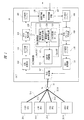
PONシステムは、OLT(局側装置、光伝送路終端装置等とも称す)10と、複数のONU(宅側装置、加入者接続装置等とも称す)20(#1:20−1、#2:20−2、#3:20−3、…、#N:20−N)と、これらの要素を接続するPON区間の光分配網ODNからなる。PON区間の光分配網は、OLT10に接続された集線光ファイバ30と、各ONU20に接続された支線光ファイバ31(31−1〜31−N)とからなり、支線光ファイバ31は、光スプリッタ(または光カプラ)32によって集線光ファイバ30から分岐されている。OLT10は、通常、キャリアやISP(Internet Service Provider)の所有するユーザ回線収容局に設置され、ONU20は、オフィスやマンション等のビル、またユーザ宅に設置される。
The PON system includes an OLT (also referred to as a station side device, an optical transmission line termination device, etc.) 10 and a plurality of ONUs (also referred to as a home side device, a subscriber connection device, etc.) 20 (# 1: 20-1, # 2: 20-2, # 3: 20-3,..., #N: 20-N) and an optical distribution network ODN in the PON section connecting these elements. The optical distribution network in the PON section includes a collecting
本実施の形態では、各ONU20のOLT10への上り方向の伝送レートが1GbpsのGE−PONをベースとしている。従って、ONU20のアクセス制御は、基本的にGE−PONの通信方式に則って行われ、ONU20がOLT10に送りたいデータ量を2バイト単位で表現したリクエスト(帯域要求:レポートとも称す)を送信し、これに対応するグラント(送信許可帯域の通知)が、2バイト単位の送信許可長と送信開始時刻で表現されるようになっている。なお、時刻は16ns毎にインクリメントされるカウンタで表現され、PONシステム内で同期がとられている。
In the present embodiment, the GE-PON whose transmission rate in the upstream direction of each
〔OLTの構成〕
図1は、OLTの内部構成を示すブロック図である。OLT10は前記動的帯域割当を行う。
[Configuration of OLT]
FIG. 1 is a block diagram showing an internal configuration of the OLT. The
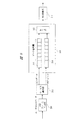
図1において、OLT10は、ONU20へ送信すべき下り信号を上位ネットワークから受信する受信回線IF部107と、受信した下り信号を一時記憶する下り受信バッファ108と、PONフレームを生成するPONフレーム生成部109と、送信すべきPONフレームを一時記憶する下り送信バッファ110と、電気信号を光信号に変換するE/O変換部111と、光信号を光ファイバへ入力する光送受信部101とを備えている。
In FIG. 1, the
また、OLT10は、上位ネットワークへ送信すべき上り光信号をONU20から受信する光送受信部101と、光信号を電気信号に変換するO/E変換部102と、受信した上り信号を一時記憶する上り受信バッファ103と、PONフレームを解析するPONフレーム解析部104と、送信すべき信号を一時記憶する上り送信バッファ105と、上位ネットワークへ送信する送信回線IF部106とを備えている。
The
更に、OLT10は、OLT制御部120として、ONU20の各々からの帯域要求量を受け付ける帯域要求受信手段、及び算出された帯域割当量に基づく送信許可をONU20の各々に送信する送信許可送信手段の機能を持つMPCP(Multi Point Control Protocol)制御部121、DBA制御部122を備えている。DBA制御部122は、受け付けた要求元毎の帯域要求量に基づいて要求元毎に次回の帯域割当量を算出する帯域割当算出手段の機能を持つ動的帯域割当算出部123、受け付けた要求元毎の帯域要求量に基づいて要求元毎に次回の帯域割当周期を算出する帯域割当周期算出手段の機能を持つ帯域割当周期算出部124、ONU管理テーブル125を備えている。
Further, the
MPCP制御部121は、データ量の帯域要求信号と送信許可帯域の通知信号を送受信する。MPCP制御部121はデータ量の帯域要求(リクエスト)を受け、動的帯域割当算出部123はそれらに割り当てるべき帯域を決定し、帯域割当周期算出部124は帯域割当周期を決定し、MPCP制御部121は送信許可帯域の通知(グラント)を行う。グラントは送信開始時刻と送信許可長とで構成される。これにより、ONU20は上り方向に所定量のデータを送出することができる。
The
〔ONUの構成〕
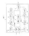
図2は、ONUの内部構成を示すブロック図である。ONU20は、前記動的帯域割当のデータ蓄積量に基づき帯域要求を行う。
[Configuration of ONU]
FIG. 2 is a block diagram showing the internal configuration of the ONU. The
図2において、ONU20は、OLT10へ送信すべき上り信号をユーザ端末から受信する受信回線IF部207と、受信した上り信号を一時記憶する上り受信バッファ208と、PONフレームを生成するPONフレーム生成部209と、送信すべきPONフレームを一時記憶する上り送信バッファ210と、電気信号を光信号に変換するE/O変換部211と、光信号を光ファイバへ入力する光送受信部201とを備えている。
2, the
また、ONU20は、ユーザ端末へ送信すべき下り光信号をOLT10から受信する光送受信部201と、光信号を電気信号に変換するO/E変換部202と、受信した下り信号を一時記憶する下り受信バッファ203と、PONフレームを解析するPONフレーム解析部204と、送信すべき信号を一時記憶する下り送信バッファ205と、ユーザ端末へ送信する送信回線IF部206とを備えている。
The
更に、ONU20は、ONU制御部220として、MPCP制御部221、バッファ監視部222を備えている。バッファ監視部222は、上り送信バッファ210のデータ蓄積量を監視する。MPCP制御部221は、バッファ監視部222からのデータ蓄積量に基づくデータ量の帯域要求信号と送信許可帯域の通知信号を送受信する。データ量の帯域要求(リクエスト)の通知を行い、OLT10から送信許可帯域の通知(グラント)を受ける。グラントは送信開始時刻と送信許可長とで構成される。これにより、ONU20は上り方向に所定量のデータを送出することができる。
Further, the
〔動的帯域割当〕
OLT10のDBA制御部122は前記集中型DBAを行う。図3は、その集中型DBAのシーケンス図である。図3に示すように、集中型DBAでは、1つのグラントGで、リクエスト用及びデータ用の帯域割当を同時に行っている。
(Dynamic bandwidth allocation)
The
各ONU20は、このグラントGに従ってリクエスト(R1〜RN)302とデータ(D1〜DN)303とをオーバヘッド帯域301を付加して別々に送信する。OLT10は、データとは別にリクエストだけを最初にかためて受信し、各ONU20のリクエストを受信し終わった時点で帯域割当処理を始めている。
Each
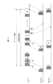
集中型DBAの代表的な一例として、帯域割当周期(グラントサイクル)の範囲で、帯域割当の不足しているONU20からのリクエストに対して優先的に帯域を割り当てていくものがあり、本実施の形態のOLT10もこのタイプの集中型DBAを行う。ONU20は、ポーリング周期毎に帯域要求信号をOLT10へ送信する。図4は、ポーリング周期と帯域割当周期が異なる場合のシーケンス図である。図4に示すように、DBAはPONにおけるデータの転送遅延を小さくすべく帯域割当周期も小さく設定することができる。
As a typical example of the centralized DBA, there is one that preferentially allocates a bandwidth to a request from the
図5は、DBA機能の処理を示すフローチャートである。MPCP制御部121はONU20からのデータの帯域要求を受け、ONU管理テーブル125を更新する(401)。動的帯域割当算出部123はONU管理テーブル125の情報に基づき、割当帯域を算出する(402)。複数のONU20のそれぞれにどれだけの通信帯域を割り当てるかを決定する動的帯域割当処理を行なう。この通信帯域は、1つの帯域周期中に送信できる総バイト長内で、どれだけのバイト長を各ONU20に割り当てるかを表わす。帯域割当周期算出部124はONU管理テーブル125の情報に基づき、帯域割当周期を算出する(403)。MPCP制御部121はONU20に割り当てられた帯域情報を含む送信許可(グラント)を通知する(404)。このグラントによる指示を受けたONU20は、そのグラントに基づいて上り方向にデータを送出する。各ONU20はOLT10からデータの送信を許可されたタイミングに、データを送信する。各ONU20は、送信を終了すべきタイミングを許可された通信バイト長で決定する。
FIG. 5 is a flowchart showing processing of the DBA function. In response to the data bandwidth request from the
図6に、データ量の帯域要求(リクエスト)と送信許可帯域の通知(グラント)の一例を示す。リクエストには、LLID501、要求帯域の値(蓄積データ量)502とデータのサービスの種類503を含む。グラントには、LLID504、送信許可長505と送信許可時間506を含む。ただし、例では、これらの値は1つしか含まないが、複数含んでもかまわない。LLID(Logical Link ID)は論理リンクであり、ONUを識別する。また、ONUは複数のバッファを備える場合、バッファ毎にLLIDを割り当てることができる。したがって、データのサービス種類毎にバッファを割り当てた場合、データのサービス種類ごとに要求帯域や送信許可を与えることができる。
FIG. 6 shows an example of a data amount bandwidth request (request) and a transmission permission bandwidth notification (grant). The request includes an
図7に、ONU管理テーブルの一例を示す。ONU管理テーブル125は、DBAの送信許可帯域の通知(グラント)を送信するための情報として、ONUID601(またはLLIDでもかまわない)と、ONU毎の割当帯域602と、帯域割当周期603と、データ要求遅延604と、スループット605とを記憶している。割当帯域602は動的帯域割当算出部123によって決定され、帯域割当周期603は帯域割当周期算出部124によって決定される。これらの決定方法については後述する。データ要求遅延604は、各ONUからの要求から送信される。また、スループット605は、オーバヘッドの必要帯域を減算した値を計算する。つまり、スループット=(割当帯域)−(オーバヘッド帯域)の関係になる。オーバヘッドとは、上述したように、保守信号やデータの同期時間からなる。
FIG. 7 shows an example of the ONU management table. The ONU management table 125 includes, as information for transmitting a notification (grant) of the transmission permission band of the DBA, an ONUID 601 (or LLID), an
以下、動的帯域割当算出部123の具体的な機能と帯域割当周期算出部124の具体的な機能を説明する。
Hereinafter, a specific function of the dynamic bandwidth
まず、通常の運用状態では、各ONU20は契約した帯域幅のみが割り当てられる。しかし、DBA機能が有効な場合、接続される全てのONU20の契約した帯域を割り当てた後、さらに未使用帯域が存在した場合にはONU20からの要求があれば、未使用領域を使用してそのONU20の帯域を増やしてもよい。このように未使用帯域を有効に利用する方法がPONシステムにおけるDBA機能である。この機能の詳細についてはITU―T勧告G.983.4を参照されたい。
First, in a normal operation state, each
動的帯域割当算出部123は、ONU20からデータ蓄積量に応じた帯域要求に基づき、通常のDBA機能を用いてONU20の割当帯域を計算する。このとき、ONU20に割り当てた帯域は同期用信号のオーバヘッドや保守用の信号も含めた帯域とする。上述したように、ONU20がデータを送信する場合、帯域割当周期毎に少なくとも1回の割合で必ず信号のレベルを調整するための信号とクロックを同期するための信号をデータの直前に送信しなければならない。このため、データを伝送するための帯域が、信号のレベルを調整する分だけ減少することになる。この帯域の減少分は、帯域割当周期が短くなるほど大きくなる。つまり、帯域割当周期を決定しないと、ONU毎のスループットを計算できない。
The dynamic bandwidth
次に、帯域割当周期の決定方法について説明する。帯域割当周期算出部124は、信号のレベルを調整するための信号とクロックを同期するための信号分の帯域とデータの要求遅延に基づき、帯域周期を決定する。
Next, a method for determining the bandwidth allocation period will be described. The band allocation
GE−PONでは、信号のレベルを調整するための信号とクロックを同期するための信号分の帯域として、レーザのON/OFF時間は512nsec、クロック同期時間は800nsecと定義されている。更に各ONU信号の間に、信号が干渉しないようにガードバンド時間が設定されており、約1μsecから5μsecである。以下これらの帯域をオーバヘッド帯域と呼ぶ。ただし、実際のパラメータは装置の設計仕様によるため、これに限らない。つまり、帯域割当周期を小さくすると、オーバヘッド帯域が増加する。 In GE-PON, a laser ON / OFF time is defined as 512 nsec and a clock synchronization time is defined as 800 nsec as a band for a signal for synchronizing a signal with a signal for adjusting a signal level. Further, a guard band time is set between the ONU signals so that the signals do not interfere with each other, and is about 1 μsec to 5 μsec. Hereinafter, these bands are referred to as overhead bands. However, the actual parameters depend on the design specifications of the apparatus and are not limited to this. That is, if the bandwidth allocation period is reduced, the overhead bandwidth increases.
例えば、ONUの帯域を300Mbps割り当てたとする。このとき、帯域割当周期を0.5msecとした場合、オーバヘッド帯域が30%とすると、スループットは210Mbps(300Mbps×70%)となる。また。帯域割当周期を2msecとした場合、オーバヘッド帯域が10%とすると、スループットは270Mbps(300Mbps×90%)となる。したがって、帯域割当周期を短くするとスループットが増加し、帯域割当周期を長くするとスループットが減少する。つまり、帯域割当周期とスループットはトレードオフの関係にある。 For example, assume that the bandwidth of the ONU is allocated at 300 Mbps. At this time, assuming that the bandwidth allocation period is 0.5 msec and the overhead bandwidth is 30%, the throughput is 210 Mbps (300 Mbps × 70%). Also. When the bandwidth allocation period is 2 msec, if the overhead bandwidth is 10%, the throughput is 270 Mbps (300 Mbps × 90%). Therefore, if the bandwidth allocation period is shortened, the throughput increases, and if the bandwidth allocation period is lengthened, the throughput decreases. That is, the bandwidth allocation period and the throughput are in a trade-off relationship.
PONシステム内のデータ転送遅延は、ONU20が、データを受信し、リクエスト信号を送信してからグラント信号を受け、データを送信するまでの時間である。この中には光ファイバの伝播遅延や装置の計算処理時間も含む。つまり、帯域割当周期は、PONシステムの要求遅延に基づき、計算すればよい。
The data transfer delay in the PON system is the time from when the
例えば、データの要求遅延が4msecの場合、リクエスト信号を送信してからグラント信号を受けるのが次の帯域割当周期範囲とすると、帯域割当周期は3msecに設定すればよい。ただし、実際のパラメータは装置の設計仕様によるため、これに限らない。したがって、データの要求遅延が4msecの場合、帯域割当周期は2msecとなり、オーバヘッド帯域が10%とすると、スループットは270Mbps(300Mbps×90%)となる。またデータの要求遅延が1msecの場合、帯域割当周期を0.5msecとなり、オーバヘッド帯域が30%とすると、スループットは210Mbps(300Mbps×70%)となる。 For example, if the data request delay is 4 msec and the next band allocation cycle range is to receive the grant signal after transmitting the request signal, the band allocation cycle may be set to 3 msec. However, the actual parameters depend on the design specifications of the apparatus and are not limited to this. Accordingly, when the data request delay is 4 msec, the bandwidth allocation period is 2 msec, and when the overhead bandwidth is 10%, the throughput is 270 Mbps (300 Mbps × 90%). If the data request delay is 1 msec, the bandwidth allocation period is 0.5 msec, and the overhead bandwidth is 30%, the throughput is 210 Mbps (300 Mbps × 70%).
帯域割当周期算出部124は、スループットが最大になるように帯域割当周期を決定する。すなわち、ONU20からの帯域要求が210Mbpsのときを考える。まず第1の例として、DBA機能の割当結果として、300Mbpsの帯域が割り当てられた場合、帯域割当周期は0.5msecで、スループット210Mbpsを満たす最小値となる。データ遅延を最小にしながら、スループット210Mbpsを達成することができる。また、第2の例として、DBA機能の割当結果として、200Mbpsの帯域が割り当てられた場合、帯域割当周期は5msec(予め設定された上限値)で、スループットが最大値190Mbpsとなる。
The bandwidth allocation
また、これらのデータ遅延については、帯域割当周期算出部124は、OLT10の外部からネットワークオペレータから要求を受け、データ要求遅延を設定してもよいし、データ信号の送信元であるサーバと連携して自動設定してもよい。
For these data delays, the bandwidth allocation
上記機能は、特にTCPのようなデータ転送の可否を確認するようなデータ転送プロトコルを用いた場合には、スループットが最大化できる。TCPのスループットはRTTに依存するため、PONシステム内のデータ転送遅延を最小化することが望ましい。一方、その結果、オーバヘッド帯域が原因でONU毎のスループットが低下してしまったのでは意味がない。 The above-described function can maximize the throughput particularly when a data transfer protocol for confirming whether data transfer is possible such as TCP is used. Since TCP throughput depends on RTT, it is desirable to minimize data transfer delay in the PON system. On the other hand, as a result, there is no point in reducing the throughput for each ONU due to the overhead bandwidth.
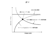
図8は、TCPのスループットを説明する図である。上述したようにオーバヘッドによるスループット限界曲線は帯域割当周期が長い方が大きくなる。これは、オーバヘッドの帯域に占める比率が減少するからである。一方、TCPの遅延によるスループット限界曲線は、帯域割当周期が長い方が小さくなる。帯域割当周期が長くなると、PON内のデータ転送遅延が大きくなり、結果として、TCPのRTTも大きくなってしまうからである。この図からわかるようにこの両者はトレードオフの関係であるが、その曲線の交点でONUのスループットが最大値になることがわかる。よって、帯域割当周期算出部124は、PONシステムにおけるTCPのスループットが最大になる帯域割当周期を算出する。
FIG. 8 is a diagram for explaining TCP throughput. As described above, the throughput limit curve due to overhead becomes larger as the bandwidth allocation period is longer. This is because the ratio of overhead to the bandwidth is reduced. On the other hand, the throughput limit curve due to TCP delay becomes smaller as the bandwidth allocation period is longer. This is because as the bandwidth allocation period becomes longer, the data transfer delay in the PON increases, and as a result, the RTT of TCP also increases. As can be seen from this figure, the two are in a trade-off relationship, but it can be seen that the throughput of the ONU reaches the maximum value at the intersection of the curves. Therefore, the bandwidth allocation
以上のように、本実施の形態によれば、OLT10において、ONU20からの要求元毎の帯域要求量に基づいて要求元毎に次回の帯域割当周期を算出し、要求元毎の帯域要求量に基づいて要求元毎に次回の帯域割当量を算出し、この算出された帯域割当量に基づく送信許可をONU20の各々に送信することで、データ遅延とオーバヘッドを考慮しながら動的帯域割当を行うようにしたので、加入者要求元毎のスループットを最大にすることができる。
As described above, according to the present embodiment, the
<実施の形態2>
本発明の実施の形態2のPONシステムについて、図9,10に基づいて説明する。
<
A PON system according to
図9は、本発明の実施の形態2のONUの内部構成を示すブロック図である。図9の例では、PONフレーム生成部209と上り送信バッファ210との間に、ユーザ端末から受信したデータのサービス種類を識別分類して転送するサービス識別手段の機能を持つサービス識別部212を備える。また、上り送信バッファ210には、TCPデータ用バッファ213、UDPデータ用バッファ214、セレクタ215を備える。他は、上述した実施の形態1と同様である。
FIG. 9 is a block diagram showing an internal configuration of the ONU according to
サービス識別部212は、受信したパケットを識別し、対応したバッファに振り分けて転送する。TCPデータ用バッファ213におけるデータ蓄積量は、MPCP制御部221により帯域要求として、OLT10に通知される。OLT10のDBA制御部122は、各ONU20からの帯域要求に基づき、割当帯域と帯域割当周期を算出する。
The
図10は、DBA機能の処理を示すフローチャートである。MPCP制御部121はONU20からのデータの帯域要求を受け、ONU管理テーブル125を更新する(901)。動的帯域割当算出部123はONU管理テーブル125の情報に基づき、割当帯域を算出する(902)。ここでは、通常のDBA割当手順にしたがい、帯域要求に基づき、帯域を割り当てる。次に、帯域割当周期算出部124はONU管理テーブル125の情報に基づき、要求帯域と割当帯域から計算されるONU20のスループットを比較する(903)。帯域割当周期算出部124は要求帯域がONU20のスループットより大きい場合、帯域割当周期を増加させる(904)。これにより、ONU20のスループットが増大する。一方、帯域割当周期算出部124は要求帯域がONU20のスループットより小さい場合、帯域割当周期を減少させる(905)。これにより、ONU20のスループットが増大する。MPCP制御部121はONU20に割り当てられた帯域情報を含む送信許可(グラント)を通知する(906)。
FIG. 10 is a flowchart showing processing of the DBA function. In response to the data bandwidth request from the
このようにONU20のスループットと帯域要求を比較して、帯域周期を増減させることにより、段階的にONU20のスループットを最適化できる。この手順を高速に行うことですばやく最適な帯域割当と帯域周期、つまりスループットとデータ遅延に近づけることが可能となる。
Thus, the throughput of the
<実施の形態3>
本発明の実施の形態3のPONシステムについて、図11に基づいて説明する。
<
A PON system according to
図11は、本発明の実施の形態3のDBA機能の処理を示すフローチャートである。本実施の形態は、データ遅延要求を各ONU20から受け付けることによっても、ONU20のスループットを最適化できる例である。
FIG. 11 is a flowchart showing processing of the DBA function according to the third embodiment of the present invention. The present embodiment is an example in which the throughput of the
MPCP制御部121はONU20からのデータの遅延要求を受け、ONU管理テーブル125を更新する(701)。動的帯域割当算出部123はONU管理テーブル125の情報に基づき、割当帯域を算出する(702)。帯域割当周期算出部124はONU管理テーブル125の情報に基づき、帯域割当周期を算出する(703)。MPCP制御部121はONU20に割り当てられた帯域情報を含む送信許可(グラント)を通知する(704)。このグラントによる指示を受けたONU20は、そのグラントに基づいて上り方向にデータを送出する。
In response to the data delay request from the
以上のように、ネットワーク構成情報がある場合や予め広域ネットワーク側のデータ転送遅延情報がある場合、この方式が有効である。例えば、提供サービスの一例として、比較的ネットワーク構成が簡単なIPTV放送ダウンロードサービスをPONシステム上で提供する場合には、OLT10の近傍にIPTVサーバが配置され、ONU20にIPTV端末が接続される形態が考えられる。この場合には、広域ネットワーク側のデータ遅延を予め知ることができるため、高速なダウンロードサービスを実現できる要求帯域やデータ遅延を計算できる。よって、各ONU20からデータ遅延要求を受け付け、ONU20のスループットを最大化できる。
As described above, this method is effective when there is network configuration information or when there is data transfer delay information on the wide area network side in advance. For example, when an IPTV broadcast download service with a relatively simple network configuration is provided on the PON system as an example of a provided service, an IPTV server is arranged in the vicinity of the
<実施の形態4>
本発明の実施の形態4のPONシステムについて、図12に基づいて説明する。
<
A PON system according to
図12は、本発明の実施の形態4のDBA機能の処理を示すフローチャートである。本実施の形態は、スループット要求を各ONU20から受け付けることによっても、ONU20のスループットを最適化できる例である。
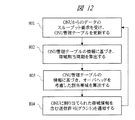
FIG. 12 is a flowchart showing processing of the DBA function according to the fourth embodiment of the present invention. The present embodiment is an example in which the throughput of the
MPCP制御部121はONU20からのスループットの要求を受け、ONU管理テーブル125を更新する(801)。各ONU20からのスループットの要求は、帯域要求(リクエスト)で行ってもよい。特にTCPのようなデータ転送の可否を確認するようなデータ転送プロトコルにおいては、帯域要求(リクエスト)の帯域要求量(502)とサービスの種類(503)の組み合わせによって、スループットの要求と判断してもよい。次に、帯域割当周期算出部124はONU管理テーブル125の情報に基づき、帯域割当周期を算出する(802)。動的帯域割当算出部123はONU管理テーブル125の情報に基づき、オーバヘッドを考慮した割当帯域を算出する(803)。MPCP制御部121はONU20に割り当てられた帯域情報を含む送信許可(グラント)を通知する(804)。このグラントによる指示を受けたONU20は、そのグラントに基づいて上り方向にデータを送出する。
In response to the throughput request from the
以上のように、ONU20のスループット要求から必要な割当帯域を逆算して、帯域を割り当てることも可能である。TCPのような転送プロトコルでは、スループットが重要となるため、スループットが最大化するような(図8)帯域割当と帯域割当周期を設定することも可能となる。
As described above, it is also possible to allocate the bandwidth by calculating back the necessary allocated bandwidth from the throughput request of the
<実施の形態5>
本発明の実施の形態5のPONシステムについて、図13に基づいて説明する。
<Embodiment 5>
A PON system according to Embodiment 5 of the present invention will be described with reference to FIG.
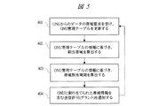
図13は、本発明の実施の形態5のDBA機能の処理を示すフローチャートである。 FIG. 13 is a flowchart showing processing of the DBA function according to the fifth embodiment of the present invention.
MPCP制御部121はONU20からのデータの帯域要求を受け、ONU管理テーブル125を更新する(811)。動的帯域割当算出部123は帯域要求に基づき、ONU20の割当帯域を算出する(812)。帯域割当周期算出部124はTCPスループットの上限とオーバヘッドによるスループットの上限を比較し、スループットが最大になるような帯域割当周期を算出する(813)。MPCP制御部121はONU20に割り当てられた帯域情報を含む送信許可(グラント)を通知する(814)。
In response to the data bandwidth request from the
以上のように、ONU20のスループット要求から必要な割当帯域を逆算して、帯域を割り当てることも可能である。TCPのような転送プロトコルでは、スループットが重要となるため、スループットが最大化するような(図8)帯域割当と帯域割当周期を設定することも可能となる。
As described above, it is also possible to allocate the bandwidth by calculating back the necessary allocated bandwidth from the throughput request of the
上記のように、TCPのようなデータ転送の可否を確認するようなデータ転送プロトコルをPONシステムで転送する場合、PONシステムの帯域を有効活用することができる。PONシステム内のデータ遅延とスループットはトレードオフの関係にあるため、これらを考慮したDBA制御を行うことで、PONシステムのスループットを向上させることができる。 As described above, when the data transfer protocol for confirming whether data transfer is possible, such as TCP, is transferred by the PON system, the bandwidth of the PON system can be effectively used. Since the data delay and throughput in the PON system are in a trade-off relationship, the throughput of the PON system can be improved by performing DBA control in consideration of these.
以上、本発明者によってなされた発明を実施の形態に基づき具体的に説明したが、本発明は前記実施の形態に限定されるものではなく、その要旨を逸脱しない範囲で種々変更可能であることはいうまでもない。 As mentioned above, the invention made by the present inventor has been specifically described based on the embodiment. However, the present invention is not limited to the embodiment, and various modifications can be made without departing from the scope of the invention. Needless to say.
本発明は、高速光アクセスネットワークに関し、更に詳しくは、光ファイバで各家庭まで高速インターネットサービスを提供できるPONシステム、およびPONシステムに適用されるOLTに利用可能である。 The present invention relates to a high-speed optical access network. More specifically, the present invention can be used for a PON system that can provide high-speed Internet service to each home using an optical fiber, and an OLT applied to the PON system.
10:OLT、20:ONU、30:集線光ファイバ、31:支線光ファイバ、32:光スプリッタ、
101:光送受信部、102:O/E変換部、103:上り受信バッファ、104:PONフレーム解析部、105:上り送信バッファ、106:送信回線IF部、107:受信回線IF部、108:下り受信バッファ、109:PONフレーム生成部、110:下り送信バッファ、111:E/O変換部、
120:OLT制御部、121:MPCP制御部、122:DBA制御部、123:動的帯域割当算出部、124:帯域割当周期算出部、125:ONU管理テーブル、
201:光送受信部、202:O/E変換部、203:下り受信バッファ、204:PONフレーム解析部、205:下り送信バッファ、206:送信回線IF部、207:受信回線IF部、208:上り受信バッファ、209:PONフレーム生成部、210:上り送信バッファ、211:E/O変換部、212:サービス識別部、213:TCPデータ用バッファ、214:UDPデータ用バッファ、215:セレクタ、
220:ONU制御部、221:MPCP制御部、222:バッファ監視部。
10: OLT, 20: ONU, 30: Concentration optical fiber, 31: Branch line optical fiber, 32: Optical splitter,
101: optical transmission / reception unit, 102: O / E conversion unit, 103: uplink reception buffer, 104: PON frame analysis unit, 105: uplink transmission buffer, 106: transmission line IF unit, 107: reception line IF unit, 108: downlink Reception buffer, 109: PON frame generation unit, 110: downlink transmission buffer, 111: E / O conversion unit,
120: OLT control unit, 121: MPCP control unit, 122: DBA control unit, 123: dynamic band allocation calculation unit, 124: band allocation period calculation unit, 125: ONU management table,
201: optical transmission / reception unit, 202: O / E conversion unit, 203: downlink reception buffer, 204: PON frame analysis unit, 205: downlink transmission buffer, 206: transmission line IF unit, 207: reception line IF unit, 208: uplink Reception buffer, 209: PON frame generation unit, 210: uplink transmission buffer, 211: E / O conversion unit, 212: service identification unit, 213: TCP data buffer, 214: UDP data buffer, 215: selector,
220: ONU control unit, 2211: MPCP control unit, 222: buffer monitoring unit.
Claims (21)
前記複数の加入者接続装置の各々からの帯域要求量を受け付ける帯域要求受信手段と、
前記帯域要求受信手段により受け付けた要求元毎の帯域要求量に基づいて、要求元毎に次回の帯域割当周期を算出する帯域割当周期算出手段と、
前記帯域要求受信手段により受け付けた要求元毎の帯域要求量に基づいて、要求元毎に次回の帯域割当量を算出する帯域割当算出手段と、
前記帯域割当算出手段により算出された帯域割当量に基づく送信許可を、前記複数の加入者接続装置の各々に送信する送信許可送信手段と、を具備することを特徴とする光伝送路終端装置。 An optical transmission line termination device connected via a light distribution network with a plurality of subscriber connection devices for accommodating user terminals,
Bandwidth request receiving means for receiving a bandwidth request amount from each of the plurality of subscriber connection devices;
A bandwidth allocation period calculating means for calculating a next bandwidth allocation period for each request source based on a bandwidth request amount for each request source received by the bandwidth request receiving means;
Based on the bandwidth request amount for each request source received by the bandwidth request reception means, bandwidth allocation calculation means for calculating the next bandwidth allocation amount for each request source;
An optical transmission line termination device comprising: transmission permission transmission means for transmitting transmission permission based on the bandwidth allocation amount calculated by the bandwidth allocation calculation means to each of the plurality of subscriber connection devices.
前記帯域割当周期算出手段は、前記加入者接続装置の前記帯域要求量が上限閾値を越えた場合、次回の帯域割当周期を増加させることを特徴とする光伝送路終端装置。 In the optical transmission line termination device according to claim 1,
The bandwidth allocation period calculating means increases the next bandwidth allocation period when the bandwidth request amount of the subscriber connection device exceeds an upper limit threshold value.
前記帯域割当周期算出手段は、前記加入者接続装置の前記帯域要求量が下限閾値を越えない場合、次回の帯域割当周期を減少させることを特徴とする光伝送路終端装置。 In the optical transmission line termination device according to claim 1,
The bandwidth allocation period calculating unit decreases the next bandwidth allocation period when the requested bandwidth of the subscriber connection device does not exceed a lower limit threshold.
前記帯域割当周期算出手段は、前記加入者接続装置の前記帯域要求量が一定範囲内の場合、次回の帯域割当周期を変動させないことを特徴とする光伝送路終端装置。 In the optical transmission line termination device according to claim 1,
An optical transmission line termination device characterized in that the bandwidth allocation cycle calculation means does not change a next bandwidth allocation cycle when the bandwidth request amount of the subscriber connection device is within a certain range.
前記帯域要求受信手段は、前記複数の加入者接続装置の各々からのデータ遅延要求を受信し、
前記帯域割当周期算出手段は、前記複数の加入者接続装置のスループットが最大になるように次回の帯域割当周期を算出することを特徴とする光伝送路終端装置。 In the optical transmission line termination device according to claim 1,
The bandwidth request receiving means receives a data delay request from each of the plurality of subscriber connection devices,
The bandwidth allocation period calculating means calculates a next bandwidth allocation period so that a throughput of the plurality of subscriber connection apparatuses is maximized.
前記帯域割当周期算出手段は、TCPスループットの上限とオーバヘッドによるスループットの上限とを比較し、前記加入者接続装置のスループットが最大になるように次回の帯域割当周期を算出することを特徴とする光伝送路終端装置。 In the optical transmission line termination device according to claim 1,
The bandwidth allocation period calculation means compares the upper limit of TCP throughput with the upper limit of throughput due to overhead, and calculates the next bandwidth allocation period so that the throughput of the subscriber connection device is maximized. Transmission line termination equipment.
前記帯域割当算出手段は、前記要求元毎のスループット要求量に基づいて、次回の帯域割当量を算出し、
前記帯域割当周期算出手段は、前記要求元毎のスループット要求量とオーバヘッドの帯域必要量に基づいて、次回の帯域割当周期を算出することを特徴とする光伝送路終端装置。 In the optical transmission line termination device according to claim 1,
The bandwidth allocation calculation means calculates a next bandwidth allocation amount based on a throughput request amount for each request source,
The bandwidth allocation period calculating means calculates a next bandwidth allocation period based on a throughput requirement amount for each request source and an overhead bandwidth requirement amount.
前記帯域割当算出手段は、前記要求元毎の帯域要求量とオーバヘッドの帯域必要量に基づいて、次回の帯域割当量を算出し、
前記帯域割当周期算出手段は、前記要求元毎の帯域要求量とオーバヘッドの帯域必要量に基づいて、次回の帯域割当周期を算出することを特徴とする光伝送路終端装置。 In the optical transmission line termination device according to claim 1,
The bandwidth allocation calculation means calculates a bandwidth allocation amount for the next time based on a bandwidth request amount and overhead bandwidth requirement for each request source,
The bandwidth allocation period calculating unit calculates a next bandwidth allocation period based on a bandwidth request amount for each request source and a bandwidth requirement amount for overhead.
前記帯域割当周期算出手段は、遅延情報と帯域割当情報から、オーバヘッドを含む帯域割当周期を算出することを特徴とする光伝送路終端装置。 In the optical transmission line termination device according to claim 1,
The bandwidth allocation period calculating means calculates a bandwidth allocation period including overhead from delay information and bandwidth allocation information.
前記光伝送路終端装置は、
前記複数の加入者接続装置の各々からの帯域要求量を受け付ける帯域要求受信手段と、
前記帯域要求受信手段により受け付けた要求元毎の帯域要求量に基づいて、要求元毎に次回の帯域割当周期を算出する帯域割当周期算出手段と、
前記帯域要求受信手段により受け付けた要求元毎の帯域要求量に基づいて、要求元毎に次回の帯域割当量を算出する帯域割当算出手段と、
前記帯域割当算出手段により算出された帯域割当量に基づく送信許可を、前記複数の加入者接続装置の各々に送信する送信許可送信手段と、を具備することを特徴とする受動光網システム。 A passive optical network system in which a plurality of subscriber connection devices for accommodating user terminals and an optical transmission line termination device connected to a wide area network are connected via an optical distribution network,
The optical transmission line termination device is:
Bandwidth request receiving means for receiving a bandwidth request amount from each of the plurality of subscriber connection devices;
A bandwidth allocation period calculating means for calculating a next bandwidth allocation period for each request source based on a bandwidth request amount for each request source received by the bandwidth request receiving means;
Based on the bandwidth request amount for each request source received by the bandwidth request reception means, bandwidth allocation calculation means for calculating the next bandwidth allocation amount for each request source;
A passive optical network system comprising: a transmission permission transmission unit that transmits a transmission permission based on a bandwidth allocation amount calculated by the band allocation calculation unit to each of the plurality of subscriber connection devices.
前記加入者接続装置は、前記ユーザ端末から受信したデータのサービス種類を識別分類して転送するサービス識別手段を具備し、
前記光伝送路終端装置は、前記サービス識別手段から転送されたサービス毎の帯域要求量に応じて帯域割当を行うことを特徴とする受動光網システム。 The passive optical network system according to claim 10, wherein
The subscriber connection device comprises service identification means for identifying and transferring a service type of data received from the user terminal;
The passive optical network system, wherein the optical transmission line termination device performs bandwidth allocation according to a bandwidth request amount for each service transferred from the service identification unit.
前記光伝送路終端装置は、
前記複数の加入者接続装置の各々からの帯域要求量を受け付け、
前記受け付けた要求元毎の帯域要求量に基づいて、要求元毎に次回の帯域割当周期を算出し、
前記受け付けた要求元毎の帯域要求量に基づいて、要求元毎に次回の帯域割当量を算出し、
前記算出された帯域割当量に基づく送信許可を、前記複数の加入者接続装置の各々に送信する、ことを特徴とする帯域割当方法。 A bandwidth allocation method in a passive optical network system in which a plurality of subscriber connection devices for accommodating user terminals and an optical transmission line termination device connected to a wide area network are connected via an optical distribution network,
The optical transmission line termination device is:
Receiving a bandwidth request amount from each of the plurality of subscriber connection devices;
Based on the received bandwidth request amount for each request source, calculate the next bandwidth allocation cycle for each request source,
Based on the received bandwidth request amount for each request source, calculate the next bandwidth allocation amount for each request source,
A bandwidth allocation method, wherein transmission permission based on the calculated bandwidth allocation amount is transmitted to each of the plurality of subscriber connection devices.
前記帯域割当周期の算出は、前記加入者接続装置の前記帯域要求量が上限閾値を越えた場合、次回の帯域割当周期を増加させることを特徴とする帯域割当方法。 The bandwidth allocation method according to claim 12,
The bandwidth allocation period is calculated by increasing the next bandwidth allocation period when the bandwidth request amount of the subscriber connection device exceeds an upper limit threshold.
前記帯域割当周期の算出は、前記加入者接続装置の前記帯域要求量が下限閾値を越えない場合、次回の帯域割当周期を減少させることを特徴とする帯域割当方法。 The bandwidth allocation method according to claim 12,
The bandwidth allocation period is calculated by reducing the next bandwidth allocation period when the bandwidth request amount of the subscriber connection apparatus does not exceed a lower limit threshold.
前記帯域割当周期の算出は、前記加入者接続装置の前記帯域要求量が一定範囲内の場合、次回の帯域割当周期を変動させないことを特徴とする帯域割当方法。 The bandwidth allocation method according to claim 12,
The bandwidth allocation method is characterized in that the bandwidth allocation cycle is calculated by not changing a next bandwidth allocation cycle when the bandwidth request amount of the subscriber connection device is within a certain range.
前記帯域要求量の受け付けは、前記複数の加入者接続装置の各々からのデータ遅延要求を受信し、
前記帯域割当周期の算出は、前記複数の加入者接続装置のスループットが最大になるように次回の帯域割当周期を算出することを特徴とする帯域割当方法。 The bandwidth allocation method according to claim 12,
The reception of the bandwidth request amount receives a data delay request from each of the plurality of subscriber connection devices,
The bandwidth allocation period is calculated by calculating a next bandwidth allocation period so that the throughput of the plurality of subscriber connection devices is maximized.
前記帯域割当周期の算出は、TCPスループットの上限とオーバヘッドによるスループットの上限とを比較し、前記加入者接続装置のスループットが最大になるように次回の帯域割当周期を算出することを特徴とする帯域割当方法。 The bandwidth allocation method according to claim 12,
The bandwidth allocation period is calculated by comparing the upper limit of the TCP throughput with the upper limit of the throughput due to overhead, and calculating the next bandwidth allocation period so that the throughput of the subscriber connection device is maximized. Assignment method.
前記帯域割当量の算出は、前記要求元毎のスループット要求量に基づいて、次回の帯域割当量を算出し、
前記帯域割当周期の算出は、前記要求元毎のスループット要求量とオーバヘッドの帯域必要量に基づいて、次回の帯域割当周期を算出することを特徴とする帯域割当方法。 The bandwidth allocation method according to claim 12,
The calculation of the bandwidth allocation amount calculates the next bandwidth allocation amount based on the throughput request amount for each request source,
The bandwidth allocation method is characterized in that the bandwidth allocation cycle is calculated based on a throughput requirement amount for each request source and a bandwidth requirement amount for overhead.
前記帯域割当量の算出は、前記要求元毎の帯域要求量とオーバヘッドの帯域必要量に基づいて、次回の帯域割当量を算出し、
前記帯域割当周期の算出は、前記要求元毎の帯域要求量とオーバヘッドの帯域必要量に基づいて、次回の帯域割当周期を算出することを特徴とする帯域割当方法。 The bandwidth allocation method according to claim 12,
The calculation of the bandwidth allocation amount is based on the bandwidth request amount for each request source and the bandwidth requirement amount of overhead, and calculates the next bandwidth allocation amount,
The bandwidth allocation method is characterized in that the bandwidth allocation cycle is calculated based on a bandwidth request amount for each request source and an overhead bandwidth requirement amount.
前記帯域割当周期の算出は、遅延情報と帯域割当情報から、オーバヘッドを含む帯域割当周期を算出することを特徴とする帯域割当方法。 The bandwidth allocation method according to claim 12,
The bandwidth allocation period is calculated by calculating a bandwidth allocation period including overhead from delay information and bandwidth allocation information.
前記加入者接続装置は、前記ユーザ端末から受信したデータのサービス種類を識別分類して転送し、
前記光伝送路終端装置は、前記転送されたサービス毎の帯域要求量に応じて帯域割当を行うことを特徴とする帯域割当方法。 The bandwidth allocation method according to claim 12,
The subscriber connection device identifies and transfers a service type of data received from the user terminal,
The bandwidth allocating method, wherein the optical transmission line termination device performs bandwidth allocation according to a bandwidth request amount for each transferred service.
Priority Applications (4)
| Application Number | Priority Date | Filing Date | Title |
|---|---|---|---|
| JP2009065463A JP2010219978A (en) | 2009-03-18 | 2009-03-18 | Optical transmission line terminal, passive optical network system, and bandwidth assignment method |
| CN201010116524.9A CN101841745A (en) | 2009-03-18 | 2010-02-10 | Optical line terminal, passive optical network system, and bandwidth assignment method |
| EP10001669A EP2230785A2 (en) | 2009-03-18 | 2010-02-18 | Optical line terminal, passive optical network system, and bandwidth assignment method |
| US12/711,827 US20100239255A1 (en) | 2009-03-18 | 2010-02-24 | Optical line terminal, passive optical network system, and bandwidth assignment method |
Applications Claiming Priority (1)
| Application Number | Priority Date | Filing Date | Title |
|---|---|---|---|
| JP2009065463A JP2010219978A (en) | 2009-03-18 | 2009-03-18 | Optical transmission line terminal, passive optical network system, and bandwidth assignment method |
Publications (2)
| Publication Number | Publication Date |
|---|---|
| JP2010219978A true JP2010219978A (en) | 2010-09-30 |
| JP2010219978A5 JP2010219978A5 (en) | 2011-08-11 |
Family
ID=42103051
Family Applications (1)
| Application Number | Title | Priority Date | Filing Date |
|---|---|---|---|
| JP2009065463A Pending JP2010219978A (en) | 2009-03-18 | 2009-03-18 | Optical transmission line terminal, passive optical network system, and bandwidth assignment method |
Country Status (4)
| Country | Link |
|---|---|
| US (1) | US20100239255A1 (en) |
| EP (1) | EP2230785A2 (en) |
| JP (1) | JP2010219978A (en) |
| CN (1) | CN101841745A (en) |
Cited By (8)
| Publication number | Priority date | Publication date | Assignee | Title |
|---|---|---|---|---|
| JP2012175477A (en) * | 2011-02-23 | 2012-09-10 | Hitachi Ltd | Dynamic band control for achieving intermittent starting of olt, optical subscriber device, and system |
| JP2012244488A (en) * | 2011-05-20 | 2012-12-10 | Fujitsu Telecom Networks Ltd | Communication system and termination device |
| JP2014011611A (en) * | 2012-06-29 | 2014-01-20 | Nippon Telegr & Teleph Corp <Ntt> | Communication system and abnormality detection method |
| JP5548289B1 (en) * | 2013-03-18 | 2014-07-16 | 日本電信電話株式会社 | Bandwidth allocation method and terminal device |
| JP2016058905A (en) * | 2014-09-10 | 2016-04-21 | 住友電気工業株式会社 | Communication device and communication system |
| JP2016111582A (en) * | 2014-12-09 | 2016-06-20 | 日本電信電話株式会社 | Bandwidth allocation device, bandwidth allocation method, and bandwidth allocation program |
| JP2017041724A (en) * | 2015-08-19 | 2017-02-23 | 日本電信電話株式会社 | Terminal station apparatus and band allocation method |
| JP2019022143A (en) * | 2017-07-20 | 2019-02-07 | 三菱電機株式会社 | Office side optical termination device |
Families Citing this family (23)
| Publication number | Priority date | Publication date | Assignee | Title |
|---|---|---|---|---|
| US8414198B2 (en) * | 2003-08-12 | 2013-04-09 | Omnitek Partners Llc | Device having a casing and/or interior acting as a communication bus between electronic components |
| US8160407B2 (en) * | 2003-08-12 | 2012-04-17 | Omnitek Partners Llc | Computer having a casing and/or interior acting as a communication bus between electronic components |
| CN101583056B (en) * | 2009-06-12 | 2012-10-03 | 华为技术有限公司 | Bandwidth processing method, network device and network system |
| US8493986B2 (en) * | 2010-05-17 | 2013-07-23 | Cox Communications, Inc. | Service gateways for providing broadband communication |
| JP5728274B2 (en) * | 2011-04-05 | 2015-06-03 | 沖電気工業株式会社 | Dynamic communication band allocation method, dynamic communication band allocation program, PON system, and station side termination device |
| JP5651548B2 (en) | 2011-06-30 | 2015-01-14 | 株式会社日立製作所 | Station side equipment, optical network system |
| CN102368691B (en) * | 2011-09-23 | 2014-07-02 | 烽火通信科技股份有限公司 | Optical link protection switching realizing method in Ethernet passive optical network system |
| US10965742B2 (en) | 2012-02-13 | 2021-03-30 | SkyKick, Inc. | Migration project automation, e.g., automated selling, planning, migration and configuration of email systems |
| JP5997088B2 (en) * | 2013-03-29 | 2016-09-28 | 株式会社日立製作所 | Dynamic bandwidth allocation method, OLT, and PON system |
| WO2014201605A1 (en) * | 2013-06-17 | 2014-12-24 | 华为技术有限公司 | Bandwidth allocation method, device, local end, terminal and system |
| WO2015023948A1 (en) * | 2013-08-16 | 2015-02-19 | Huawei Technologies Co., Ltd. | Traffic-bearing entity identification in multiple-wavelength passive optical networks (pons) |
| US10129086B2 (en) * | 2013-08-28 | 2018-11-13 | Telefonaktiebolaget Lm Ericsson (Publ) | Collection of performance data in a communications network |
| CN103957475A (en) * | 2014-04-11 | 2014-07-30 | 烽火通信科技股份有限公司 | Networking system allowing GPON and XG-PON to be concomitant and application |
| CN105247928B (en) * | 2014-05-06 | 2019-04-12 | 华为技术有限公司 | A kind of device and method for realizing cell coordination work |
| US10122640B2 (en) * | 2015-01-26 | 2018-11-06 | LiveQoS Inc. | Minimal buffer network arbiter |
| US10771452B2 (en) | 2015-03-04 | 2020-09-08 | SkyKick, Inc. | Autonomous configuration of email clients during email server migration |
| US10592483B2 (en) | 2015-04-05 | 2020-03-17 | SkyKick, Inc. | State record system for data migration |
| JP6674023B2 (en) * | 2016-06-20 | 2020-04-01 | 日本電信電話株式会社 | Optical transmission device and band allocation method |
| CN110870259B (en) * | 2017-07-19 | 2022-04-01 | 日本电信电话株式会社 | Virtual subscriber line terminal station device and control method of virtual subscriber line terminal station device |
| CN107465742B (en) * | 2017-08-02 | 2023-06-23 | 上海欣诺通信技术股份有限公司 | Distribution equipment and method for realizing asymmetric service by UDP tunnel technology |
| CN109348315B (en) * | 2018-10-15 | 2021-01-26 | 中天宽带技术有限公司 | Dynamic bandwidth allocation method for adjusting bandwidth allocation parameters based on time division multiplexing |
| CN112350778B (en) * | 2019-08-09 | 2022-06-14 | 瑞昱半导体股份有限公司 | Optical network unit and method for transmitting dynamic bandwidth report uplink information |
| DE102019126173A1 (en) * | 2019-09-27 | 2021-04-01 | Intel Corporation | DEVICES, METHODS AND COMPUTER PROGRAMS FOR A REMOTE UNIT AND A CENTRAL UNIT OF AN OPTICAL LINE TERMINAL |
Citations (1)
| Publication number | Priority date | Publication date | Assignee | Title |
|---|---|---|---|---|
| JP2003258824A (en) * | 2002-03-01 | 2003-09-12 | Nippon Telegr & Teleph Corp <Ntt> | Band assignment method in point-to-multipoint communication system |
Family Cites Families (3)
| Publication number | Priority date | Publication date | Assignee | Title |
|---|---|---|---|---|
| JP4056018B2 (en) * | 1998-01-23 | 2008-03-05 | 株式会社東芝 | Point / multipoint communication system |
| US7127167B2 (en) * | 2001-07-05 | 2006-10-24 | Broadcom Corporation | System for spectrum allocation in ethernet-based fiber optic TDMA networks |
| CN101252789B (en) * | 2008-03-20 | 2011-04-06 | 华为技术有限公司 | Method and apparatus for allocating multi-frame dynamic band width |
-
2009
- 2009-03-18 JP JP2009065463A patent/JP2010219978A/en active Pending
-
2010
- 2010-02-10 CN CN201010116524.9A patent/CN101841745A/en active Pending
- 2010-02-18 EP EP10001669A patent/EP2230785A2/en not_active Withdrawn
- 2010-02-24 US US12/711,827 patent/US20100239255A1/en not_active Abandoned
Patent Citations (1)
| Publication number | Priority date | Publication date | Assignee | Title |
|---|---|---|---|---|
| JP2003258824A (en) * | 2002-03-01 | 2003-09-12 | Nippon Telegr & Teleph Corp <Ntt> | Band assignment method in point-to-multipoint communication system |
Cited By (8)
| Publication number | Priority date | Publication date | Assignee | Title |
|---|---|---|---|---|
| JP2012175477A (en) * | 2011-02-23 | 2012-09-10 | Hitachi Ltd | Dynamic band control for achieving intermittent starting of olt, optical subscriber device, and system |
| JP2012244488A (en) * | 2011-05-20 | 2012-12-10 | Fujitsu Telecom Networks Ltd | Communication system and termination device |
| JP2014011611A (en) * | 2012-06-29 | 2014-01-20 | Nippon Telegr & Teleph Corp <Ntt> | Communication system and abnormality detection method |
| JP5548289B1 (en) * | 2013-03-18 | 2014-07-16 | 日本電信電話株式会社 | Bandwidth allocation method and terminal device |
| JP2016058905A (en) * | 2014-09-10 | 2016-04-21 | 住友電気工業株式会社 | Communication device and communication system |
| JP2016111582A (en) * | 2014-12-09 | 2016-06-20 | 日本電信電話株式会社 | Bandwidth allocation device, bandwidth allocation method, and bandwidth allocation program |
| JP2017041724A (en) * | 2015-08-19 | 2017-02-23 | 日本電信電話株式会社 | Terminal station apparatus and band allocation method |
| JP2019022143A (en) * | 2017-07-20 | 2019-02-07 | 三菱電機株式会社 | Office side optical termination device |
Also Published As
| Publication number | Publication date |
|---|---|
| CN101841745A (en) | 2010-09-22 |
| EP2230785A2 (en) | 2010-09-22 |
| US20100239255A1 (en) | 2010-09-23 |
Similar Documents
| Publication | Publication Date | Title |
|---|---|---|
| JP2010219978A (en) | Optical transmission line terminal, passive optical network system, and bandwidth assignment method | |
| US9793993B2 (en) | Method and apparatus of delivering upstream data in ethernet passive optical network over coaxial network | |
| US6546014B1 (en) | Method and system for dynamic bandwidth allocation in an optical access network | |
| US9331812B2 (en) | Round trip time aware dynamic bandwidth allocation for ethernet passive optical network over coaxial network | |
| JP4410818B2 (en) | Passive optical network system and station side optical transmission line termination device | |
| US7822063B2 (en) | Bandwidth allocation method and system for data transmission in EPON | |
| KR100775427B1 (en) | System and Method for Bandwidth Allocation In GPON | |
| TWI725274B (en) | Data communication system, optical line terminal and baseband unit | |
| JP5216656B2 (en) | Passive optical network system and operation method thereof | |
| US9071380B2 (en) | Multi-point control protocol proxy architecture in a network with optical and coaxial domains | |
| US8184976B2 (en) | Passive optical network system and operating method thereof | |
| US20090274461A1 (en) | Pon multicast communication system, multicast management method, and corresponding devices | |
| WO2012090274A1 (en) | Relay device, station side optical communication device, communication system, and bandwidth allocation method | |
| JP2012518319A (en) | Output separation for dynamic bandwidth allocation in passive optical networks | |
| EP2949129B1 (en) | Transmission prioritization based on polling time | |
| JP5257623B2 (en) | Station side device, line concentrator, communication system, and bandwidth allocation method | |
| JP4926193B2 (en) | Passive optical network system and station side optical transmission line termination device | |
| JP4877483B2 (en) | Transmission allocation method and apparatus | |
| KR100719896B1 (en) | An Adaptive Limited Bandwidth Allocation Scheme for EPON | |
| JP2011166328A (en) | Optical transmission system, optical line terminal and upward transmission control method | |
| JP6093282B2 (en) | Optical communication system, communication control method, and station side optical line terminator | |
| JP5487293B2 (en) | Passive optical network system and operation method thereof | |
| KR100799583B1 (en) | The onu buffer size modeling and the data transmission delay in epon(ethernet passive optical network) | |
| Morshed et al. | Dynamic Hybrid Slot Size Bandwidth Allocation Algorithm for Reducing Packet Delay of Real Time Traffic in EPON | |
| Kwong et al. | WDM PONs: Next step for the first mile |
Legal Events
| Date | Code | Title | Description |
|---|---|---|---|
| A521 | Request for written amendment filed |
Free format text: JAPANESE INTERMEDIATE CODE: A523 Effective date: 20110629 |
|
| A621 | Written request for application examination |
Free format text: JAPANESE INTERMEDIATE CODE: A621 Effective date: 20110629 |
|
| A977 | Report on retrieval |
Free format text: JAPANESE INTERMEDIATE CODE: A971007 Effective date: 20121122 |
|
| A131 | Notification of reasons for refusal |
Free format text: JAPANESE INTERMEDIATE CODE: A131 Effective date: 20121204 |
|
| A02 | Decision of refusal |
Free format text: JAPANESE INTERMEDIATE CODE: A02 Effective date: 20131203 |