JP2010206643A - Image capturing apparatus and method, and program - Google Patents
Image capturing apparatus and method, and program Download PDFInfo
- Publication number
- JP2010206643A JP2010206643A JP2009051138A JP2009051138A JP2010206643A JP 2010206643 A JP2010206643 A JP 2010206643A JP 2009051138 A JP2009051138 A JP 2009051138A JP 2009051138 A JP2009051138 A JP 2009051138A JP 2010206643 A JP2010206643 A JP 2010206643A
- Authority
- JP
- Japan
- Prior art keywords
- image
- optical system
- imaging
- unit
- distance
- Prior art date
- Legal status (The legal status is an assumption and is not a legal conclusion. Google has not performed a legal analysis and makes no representation as to the accuracy of the status listed.)
- Pending
Links
Images


Abstract
Description
本発明は、複数の撮像光学系を有し、多視点から画像を取得可能な撮像装置に関する。 The present invention relates to an imaging apparatus having a plurality of imaging optical systems and capable of acquiring images from multiple viewpoints.
特許文献1では、立体映像撮影記録再生装置1に用いられる立体映像撮影装置を、2台のビデオカメラ2R,2Lにより構成する。この2台のうちの一方のビデオカメラ2Rの撮像レンズ2aにズームレンズを用い、他方のビデオカメラ2Lの撮像レンズ2a′に固定倍率レンズを用いる。通常の2次元(2D)画像を撮影するときには、ワイドと望遠の拡大された画像を同時に撮影し、任意に切り換えられるようにしてある。その結果、3次元(3D)のときはもちろん、2Dを撮影するときにも、2台のビデオカメラ2R,2Lをフルに活用しての撮影が可能となる。また、3D撮影時のズームは、いわゆる電子ズームで行うので、複雑な機構が不要になる。
In Patent Document 1, a stereoscopic video imaging apparatus used for the stereoscopic video imaging recording / reproducing apparatus 1 is configured by two video cameras 2R and 2L. A zoom lens is used for the
特許文献2では、カメラ装置が、望遠画像の撮影時点において、広角カメラ部の撮影視野における望遠カメラ部の撮像範囲の情報を取得するとともに、該撮像範囲を表示するのにより正確である広角画像を判定する手段によって、望遠画像に対応付ける広角画像を決定し、撮影した望遠画像を、撮像範囲情報及び広角画像を特定する情報とともに送信する。カメラ装置と離れた場所で撮影映像を再生する装置では、各望遠画像が特定する広角画像の表示上に、望遠撮像範囲を示すことができるように、望遠映像の再生を広角映像の再生に同期させる。 In Patent Document 2, the camera device acquires information on the imaging range of the telephoto camera unit in the field of view of the wide-angle camera unit at the time of capturing the telephoto image, and displays a wide-angle image that is more accurate for displaying the imaging range. The determination means determines a wide-angle image to be associated with the telephoto image, and transmits the captured telephoto image together with imaging range information and information specifying the wide-angle image. For devices that play back video shots away from the camera device, telephoto playback is synchronized with wide-angle video playback so that the telephoto imaging range can be shown on the wide-angle image specified by each telephoto image. Let
特許文献3、4および5は、被写体距離の測定の一例を示す。特許文献3はTOF(Time of Flight)を例示する。すなわち、距離情報処理手段は、2つの距離用発光素子から照射された光が被写体で反射されて2つの距離用撮像素子に返ってくるまでの時間を測定し、所定の数式に基づいて距離用撮像素子の捉えた被写体までの距離を算出する。そして、算出された結果を用いて、各画素の画素値が距離の値である距離画像をそれぞれ生成する。 Patent Documents 3, 4 and 5 show examples of measurement of the subject distance. Patent Document 3 exemplifies TOF (Time of Flight). That is, the distance information processing means measures the time until the light emitted from the two distance light emitting elements is reflected by the subject and returns to the two distance image pickup elements, and is based on a predetermined mathematical formula. The distance to the subject captured by the image sensor is calculated. Then, a distance image in which the pixel value of each pixel is a distance value is generated using the calculated result.
特許文献4では、TOFのほか、AF機能を用いて顔に合焦した際のレンズ21の位置を用いて被写体までの距離を測定するようにしても良いとする。
In Patent Document 4, in addition to the TOF, the distance to the subject may be measured using the position of the
特許文献5では、レンズを通してピント調整を行う、いわゆるTTL(Thru The Lens)測距を行うものとして、撮像素子(CCD)を用いるものやパッシブ型測距用受光センサを用いるもの等があるとする。 In Patent Document 5, it is assumed that there are those using an imaging element (CCD), a passive type light receiving sensor for distance measurement, etc. as what performs so-called TTL (Thru The Lens) distance measurement that performs focus adjustment through a lens. .
特許文献1では、2D撮影時のスルー画像は、2画像を並列配置するので、同時に撮像範囲を確認するのが難しい。 In Patent Document 1, since two through images are arranged in parallel during 2D shooting, it is difficult to check the imaging range at the same time.
特許文献2では、異なる画角を持つ複数の光学系によって被写体を同時に撮影する際、広角側画像の中に望遠側の撮像範囲の枠を表示する技術が開示されている。しかし、複数の光学系の光軸が一致していない場合、被写体距離によって撮像範囲の相対的位置が変化してしまい、望遠側の撮像範囲を正しく表示することができなかった。 Patent Document 2 discloses a technique for displaying a frame of a telephoto-side imaging range in a wide-angle image when a subject is simultaneously photographed by a plurality of optical systems having different angles of view. However, when the optical axes of the plurality of optical systems do not match, the relative position of the imaging range changes depending on the subject distance, and the imaging range on the telephoto side cannot be displayed correctly.
本発明は、被写体距離に関わらず、広角側の画角に対する望遠側の撮像範囲を正しく表示して、使い勝手のよい複眼の撮像装置を実現することを目的とする。 An object of the present invention is to realize an easy-to-use compound-eye imaging apparatus by correctly displaying a telephoto-side imaging range with respect to a wide-angle-side field angle regardless of the subject distance.
本発明に係る撮像装置は、第1の光学系および第2の光学系の各々を介して結像した被写体像を撮像素子により光電変換して第1の光学系に対応する画像である第1の画像および第2の光学系に対応する画像である第2の画像を出力可能な撮像部と、第1の光学系のズーム位置を広角側に設定するとともに、第2の光学系のズーム位置を望遠側に設定するズーム調節部と、被写体までの距離を測定する測距部と、測距部の測定した距離に応じて、第1の光学系の撮像範囲における第2の光学系の相対的な撮像範囲を決定する範囲決定部と、範囲決定部の決定した第2の光学系の相対的な撮像範囲を示す映像を第1の第1の光学系の撮像範囲を示す映像に重畳して所定の表示装置に表示するよう制御する制御部と、を備える。 An image pickup apparatus according to the present invention is a first image corresponding to a first optical system obtained by subjecting a subject image formed through each of a first optical system and a second optical system to photoelectric conversion by an image pickup device. An imaging unit capable of outputting a second image that is an image corresponding to the second optical system and the second optical system, and the zoom position of the first optical system is set to the wide-angle side, and the zoom position of the second optical system A zoom adjustment unit that sets the distance to the telephoto side, a distance measurement unit that measures the distance to the subject, and a relative value of the second optical system in the imaging range of the first optical system according to the distance measured by the distance measurement unit A range determining unit that determines a typical imaging range, and an image that indicates a relative imaging range of the second optical system determined by the range determining unit is superimposed on an image that indicates the imaging range of the first first optical system. And a control unit that controls to display on a predetermined display device.
範囲決定部は、第1の光学系の撮像範囲を示す映像の中心位置から第2の光学系の相対的な撮像範囲を示す映像の中心位置までの距離Dを、Hは第1の光学系の撮像範囲を示す映像の幅、Lは測距部の測定した距離、SBは基線長、Lxは撮像装置からクロスポイントまでの距離、θaは第1の光学系の半画角、Waは距離Lにおける第1の光学系の撮像範囲(幅)、dは距離Lにおける第1および第2の光学系の光軸間距離であり、Lx≫SBであるとして
D=H×d/Wa
d=SB×(Lx−L)/Lx
Wa≒2×L×tanθa
により決定する。
The range determination unit is a distance D from the center position of the image indicating the imaging range of the first optical system to the center position of the image indicating the relative imaging range of the second optical system, and H is the first optical system. , L is the distance measured by the distance measuring unit, SB is the base line length, Lx is the distance from the imaging device to the cross point, θa is the half angle of view of the first optical system, and Wa is the distance The imaging range (width) of the first optical system at L, d is the distance between the optical axes of the first and second optical systems at the distance L, and assuming that Lx >> SB, D = H × d / Wa
d = SB × (Lx−L) / Lx
Wa≈2 × L × tan θa
Determined by
範囲決定部は、所定の表示装置の画面上での第2の光学系の撮像範囲を示す映像の幅H’を、θbは第2の光学系の半画角、Wbは距離Lにおける第2の光学系の撮像範囲(幅)であり、Lx≫SBであるとして
H’=H×Wb/Wa=H×tanθb/tanθa
により決定する。
The range determining unit sets the video width H ′ indicating the imaging range of the second optical system on the screen of a predetermined display device, θb is the half angle of view of the second optical system, and Wb is the second width at the distance L. Assuming that Lx >> SB, H ′ = H × Wb / Wa = H × tan θb / tan θa
Determined by
制御部は、範囲決定部の決定した第2の光学系の相対的な撮像範囲を示す映像を第1の画像に重畳して所定の表示装置に表示するよう制御する。 The control unit performs control so that a video indicating the relative imaging range of the second optical system determined by the range determination unit is superimposed on the first image and displayed on a predetermined display device.
制御部は、第2の光学系の相対的な撮像範囲を示す映像として第2の画像をはめ込み合成するよう制御する。 The control unit performs control so that the second image is inserted and combined as an image indicating the relative imaging range of the second optical system.
第2の画像はスルー画像を含む。 The second image includes a through image.
第1の画像はスルー画像を含む。 The first image includes a through image.
撮像部の出力した第1の画像および第2の画像を記録可能な記録部を備える。 A recording unit capable of recording the first image and the second image output from the imaging unit is provided.
本発明に係る撮像方法は、第1の光学系および第2の光学系の各々を介して結像した被写体像を撮像素子により光電変換して第1の光学系に対応する画像である第1の画像および第2の光学系に対応する画像である第2の画像を出力可能な撮像部と、第1の光学系のズーム位置を広角側に設定するとともに、第2の光学系のズーム位置を望遠側に設定するズーム調節部と、被写体までの距離を測定する測距部と、を備えた撮像装置が、測距部の測定した距離に応じて、第1の光学系の撮像範囲における第2の光学系の相対的な撮像範囲を決定するステップと、決定した第2の光学系の相対的な撮像範囲を示す映像を第1の第1の光学系の撮像範囲を示す映像に重畳して所定の表示装置に表示するよう制御するステップと、を実行する。 The imaging method according to the present invention is a first image that corresponds to the first optical system by subjecting a subject image formed through each of the first optical system and the second optical system to photoelectric conversion by an imaging device. An imaging unit capable of outputting a second image that is an image corresponding to the second optical system and the second optical system, and the zoom position of the first optical system is set to the wide-angle side, and the zoom position of the second optical system An image pickup apparatus including a zoom adjustment unit that sets the distance to the telephoto side and a distance measurement unit that measures the distance to the subject in the imaging range of the first optical system according to the distance measured by the distance measurement unit. Determining a relative imaging range of the second optical system, and superimposing an image showing the determined relative imaging range of the second optical system on an image showing the imaging range of the first optical system And controlling to display on a predetermined display device.
この撮像方法を撮像装置に実行させるためのプログラムも本発明に含まれる。 A program for causing the imaging apparatus to execute this imaging method is also included in the present invention.
本発明によると、広角側の撮像光学系の撮像範囲に対する望遠側の撮像光学系の撮像範囲の大きさと相対的位置を被写体までの距離に応じて正確に表示するので、異なる光学系で広角撮影と望遠撮影を同時に行う場合、双方の画角を把握させやすくし、操作性をよくすることができる。 According to the present invention, since the size and relative position of the imaging range of the telephoto imaging system relative to the imaging range of the wide-angle imaging optical system are accurately displayed according to the distance to the subject, wide-angle shooting is performed with different optical systems. And telephoto shooting at the same time, it is easy to grasp the angle of view of both, and the operability can be improved.
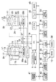
図1はカメラ1の電気的構成を示す。第1撮像部2aは、レンズ光軸L1に沿って配列された第1ズームレンズ11、第1絞り12、第1フォーカスレンズ13を含む第1撮像光学系、及び第1イメージセンサ14によって構成されている。第1ズームレンズ11にはレンズモータ15、第1絞り12にはアイリスモータ16、第1フォーカスレンズ13にはレンズモータ17が接続されており、また、第1イメージセンサ14にはタイミングジェネレータ(TG)18が接続されている。モータ15〜17、及びTG18の動作はCPU19によって制御され、モータ15〜17の実際の駆動開始および終了はCPU19の制御に従ってモータドライバ29が指示する。
FIG. 1 shows the electrical configuration of the camera 1. The
レンズモータ15は、操作部9からのズーム操作に応じて、第1ズームレンズ11をレンズ光軸L1に沿ってTELE側(繰り出し側)、或いはWIDE側(繰り込み側)に移動させ、ズーム倍率を変化させる。アイリスモータ16は、AE(Auto Exposure)動作時に第1絞り12の開口値(絞り値)を変化させて光束を制限し、露出調整を行う。レンズモータ17は、AF(Auto Focus)動作時に第1フォーカスレンズ13をレンズ光軸L1に沿ってNEAR側(繰り出し側)、或いはINF側(繰り込み側)に移動させて合焦位置を変え、ピント調整を行う。
The
第1イメージセンサ14は、CCDやCMOSなどの固体撮像素子で構成され、第1ズームレンズ11、第1絞り12、及び第1フォーカスレンズ13によって結像された被写体光を受光し、受光素子に受光量に応じた光電荷を蓄積する。第1イメージセンサ14の光電荷蓄積・転送動作は、TG18によって制御され、TG18から入力されるタイミング信号(クロックパルス)により、電子シャッタ速度(光電荷蓄積時間)が決定される。第1イメージセンサ14は、撮影モード時には、1画面分の画像信号を所定周期ごとに取得し、順次、撮像回路28aに入力する。
The
第2撮像部2bは、第1撮像部2aと同一の構成であり、レンズ光軸L2に沿って配列された第2ズームレンズ20、第2絞り21、第2フォーカスレンズ22を含む第2撮像光学系、レンズモータ24が接続された第2ズームレンズ20、アイリスモータ25が接続された第2絞り21、レンズモータ26が接続された第2フォーカスレンズ22、及びタイミングジェネレータ(TG)27が接続された第2イメージセンサ23によって構成されている。モータ24〜26、及びTG27の動作はCPU19によって制御される。第1撮像部2aと第2撮像部2bとは、基本的に連動して動作を行うが、各々個別に動作させることも可能となっている。よって、一方で静止画、他方で動画を撮影したり、双方で静止画だけ、あるいは双方で動画だけを撮影することもできる。なお、第1及び第2イメージセンサ14,23として、CCD型やCMOS型のイメージセンサが用いられる。第1撮像部2aと第2撮像部2bとは、1つの筐体に一体的に構成されてもよいが、別々でもよい。
The
第1及び第2イメージセンサ14,23から出力された撮像信号は、それぞれ撮像回路28a、b(まとめて撮像回路28と表記)に含まれる相関二重サンプリング回路(CDS)に入力される。CDSは、第1及び第2イメージセンサ14,23の各受光素子の蓄積電荷量に正確に対応したR,G,Bの画像データを、撮像回路28に含まれる増幅器(AMP)に入力する。AMPは、入力された画像データを増幅し、撮像回路28に含まれるA/D変換器に入力する。A/D変換器は、入力された画像データをアナログからデジタルに変換する。撮像回路28に含まれるCDS、AMP、A/D変換器を通して、第1イメージセンサ14の撮像信号は第1画像データ(左眼用画像データ)として、第2イメージセンサ23の撮像信号は第2画像データ(右眼用画像データ)として出力される。
The imaging signals output from the first and
画像信号処理回路31は、階調変換、ホワイトバランス補正、γ補正処理などの各種画像処理をA/D変換器から入力された第1及び第2画像データに施す。フレームメモリ32は、画像信号処理回路31で各種画像処理が施された第1及び第2画像データを一時的に格納する。
The image
評価値算出回路33は、フレームメモリ32に格納された第1及び第2画像データの各々からAF評価値及びAE評価値を算出する。AF評価値は、各画像データの全領域又は所定領域(例えば中央部)について輝度値の高周波成分を積算することにより算出され、画像の鮮鋭度を表す。輝度値の高周波成分とは、隣接する画素間の輝度差(コントラスト)を所定領域内について足し合わせたものである。また、AE評価値は、各画像データの全領域又は所定領域(例えば中央部)について輝度値を積算することにより算出され、画像の明るさを表す。AF評価値及びAE評価値は、公知のAF動作(自動焦点制御)及びAE動作(自動露出制御)においてそれぞれ使用される。
The evaluation
パノラマ画像処理回路40は、操作部9からパノラマ撮影モードが選択された場合、フレームメモリ32に格納されている第1及び第2イメージセンサ14,23で得られた第1及び第2画像データの重なる領域を繋ぐような関連付けおよび合成を行う。パノラマ画像処理回路40の合成した画像をパノラマ画像という。パノラマ画像処理回路40は、パノラマ画像をフレームメモリ32に記憶し、このパノラマ画像データが、表示制御部35を介して表示部10にスルー画として表示される。スルー画とは、第1及び第2イメージセンサ14,23で所定時間間隔で継続的に撮影される画像である。
When the panoramic shooting mode is selected from the operation unit 9, the panoramic
表示制御部35は、CPU19の指示に従い、OSD信号発生回路46に対し、シャッタ速度や絞り値、撮影可能枚数、撮影日時、警告メッセージ、グラフィカルユーザインターフェイス(GUI)、後述する望遠側の撮像範囲の枠等の文字、記号及び映像情報を表示するための信号を発生させるコマンドを送る。OSD信号発生回路46から出力される信号は、必要に応じて撮像回路28a・28bからの画像信号に混合されて、LCDなどで構成された表示部10に供給される。これにより、スルー画像や再生画像に文字等が合成された合成画像が表示される。
The
立体画像処理回路34は、操作部9から立体撮影モードが選択された場合、フレームメモリ32に格納されている第1及び第2画像データを、表示部10が立体表示を行うための立体画像データに合成する。撮影モード時に表示部10が電子ビューファインダとして使用される際には、立体画像処理回路34によって合成された立体画像データが、表示制御部35を介して表示部10にスルー画として表示される。
When the stereoscopic shooting mode is selected from the operation unit 9, the stereoscopic
個別画像処理回路41は、操作部9から2枚同時撮影モードが選択された場合、第1及び第2画像データをそれぞれ独立した個別画像データに構成し、個別画像データは、OSD信号発生回路46から供給された区切り枠の映像などで区別された上、それぞれ表示制御部35を介して表示部10にスルー画として表示される。
The individual
圧縮伸張処理回路36は、シャッタボタン5から撮影指示が入力されたことに応じてフレームメモリ32に記憶された静止画像データ(パノラマ画像データ、立体画像データ、個別画像データ)に対して、JPEG方式等の圧縮形式により圧縮処理を施す。動画撮影モードが選択指示された場合はMPEG4などの圧縮形式により圧縮処理を施す。メモリ制御部37は、圧縮伸張処理回路36によって圧縮処理された画像データをメモリカード等の記録媒体38に記録させる。なお、異なる光学系に対応した画像データを1つの画像ファイル内に記録してもよいし、2つ以上の独立した画像ファイルとしてもよい。ただし、2つの独立した画像ファイルの付帯情報(ヘッダ情報、タグ情報その他)には、画像データを撮影した第1撮像部2aの識別情報(例えば「1」)または第2撮像部2bの識別情報(例えば「2」)と撮影日時情報と撮影時に選択されていた撮影モードが記録され、撮影日時情報の同一性によって同時に撮影された2枚の画像の関連づけを行う。
The compression /
このようにして記録媒体38に記録された画像データを表示部10に再生表示する場合、記録媒体38の各画像データは、メモリ制御部37によって読み出され、圧縮伸張処理回路36によって伸張処理が行われる。
When the image data recorded on the
読み出された画像データに対応する付帯情報の撮影モードが、パノラマ撮影モードの場合、画像データは、重複領域が重畳された平面のパノラマ画像に変換された後、表示制御部35を介して表示部10に再生画像として表示される。
When the shooting mode of the incidental information corresponding to the read image data is the panorama shooting mode, the image data is converted into a flat panoramic image on which the overlapping area is superimposed and then displayed via the
読み出された画像データに対応する付帯情報の撮影モードが、立体撮影モードの場合、画像データは、立体画像処理回路34によって立体画像データに変換された後、表示制御部35を介して表示部10に再生画像として表示される。
When the shooting mode of the supplementary information corresponding to the read image data is the stereoscopic shooting mode, the image data is converted into stereoscopic image data by the stereoscopic
読み出された画像データに対応する付帯情報の撮影モードが、2枚同時撮影モードの場合、同一の撮影日時情報がヘッダ情報に記録された2枚の画像ファイルの画像データ(静止画、動画いずれも可)の各々を、表示部10の同一画面に、撮像光学系の識別情報に対応した位置(2眼の撮像系では左側または右側)に配置した再生画像として表示される。
When the shooting mode of the incidental information corresponding to the read image data is the two-frame simultaneous shooting mode, the image data of the two image files in which the same shooting date / time information is recorded in the header information (either a still image or a moving image) Are displayed on the same screen of the
表示部10の詳細な構造は図示しないが、表示部10は、その表面にパララックスバリア表示層を備えている。表示部10は、立体表示を行う際に、パララックスバリア表示層に光透過部と光遮蔽部とが交互に所定のピッチで並んだパターンからなるパララックスバリアを発生させるとともに、その下層の画像表示面に左右の像を示す短冊状の画像断片を交互に配列して表示することで擬似的な立体視を可能にする。なお、第1撮像部2aおよび第2撮像部2bから得られた平面画像を短冊状の画像断片に再構成してこれらを交互に配列せず、第1撮像部2aまたは第2撮像部2bの一方から得られた右あるいは左の像のみを短冊状の画像断片に再構成してこれらを交互に配列すれば、観者の右目も左目も同一の平面画像を視覚することになる。
Although the detailed structure of the
CPU19は、カメラ1の全体の動作を統括的に制御する。CPU19には、前述のシャッタボタン5、操作部9のほか、不揮発性メモリであるEEPROM39が接続されている。EEPROM39は、各種制御用のプログラムや設定情報などを格納している。CPU19は、このプログラムや設定情報に基づいて各種処理を実行する。
The
シャッタボタン5は2段押しのスイッチ構造となっている。撮影モード中に、シャッタボタン5が軽く押圧(半押し)されると、CPU19はAF動作及びAE動作を開始し撮影準備処理がなされる。この状態でさらにシャッタボタン5が強く押圧(全押し)されると、CPU19は撮影処理を開始し、1画面分の第1及び第2画像データがフレームメモリ32から記録媒体38に転送されて記録される。
The shutter button 5 has a two-stage push switch structure. When the shutter button 5 is lightly pressed (half-pressed) during the shooting mode, the
AF動作は、CPU19がレンズモータ17,26を制御して第1及び第2フォーカスレンズ13,22をそれぞれ所定方向に移動させながら、順次に得られる第1及び第2画像データの各々から評価値算出回路33が算出したAF評価値の最大値を求めることによりなされる。AE動作は、AF動作が完了した後、評価値算出回路33が算出したAE評価値に基づいて、CPU19がアイリスモータ18,27及びTG18,27を制御し、第1及び第2絞り12,21の開口値(絞り値)、及び第1及び第2イメージセンサ14,23の電子シャッタ速度をEEPROM39に予め格納されたプログラム線図に従って設定することによりなされる。
In the AF operation, the
測距部45は、被写体までの距離を測定し、その測定した距離をCPU19に出力する。被写体距離の測定方式は公知のもの、例えば特許文献3〜5に記載されるTOF、三角測距、TTL方式などが採用できる。ただし、測距部45が測距センサを採用する場合、測距部45の光軸がクロスポイント(図3参照)に向かうよう、睨み角(測距センサの被写体側に延びる光軸と、撮影光学系の被写体側に延びる光軸との間の角度)を調整する必要がある。
The
図2はCPU19が実行を制御する撮影処理のフローチャートである。この処理をCPU19に実行させるプログラムはEEPROM39に記憶されている。この処理は、操作部9から「立体撮影モード」、「パノラマ撮影モード」または「2枚同時撮影モード」の中から「2枚同時撮影モード」が選択されたことに応じて開始する。なお、操作部9から「2枚同時撮影モード」の選択指示が入力された場合、記録する画像データの形式である「静止画」、「動画」または「静止画および動画の両方」を選択させて、選択された形式に対応する記録方式で画像を記録してもよい。
FIG. 2 is a flowchart of a photographing process that the
S1では、第1撮像部2aの第1ズームレンズ11を広角側に設定するようモータドライバに指示するとともに、第2撮像部2bの第2ズームレンズ20を望遠側に設定するようモータドライバに指示する。説明の都合上、広角・望遠の設定は上記のようにするが、当然ながら第1撮像部2aの第1ズームレンズ11を望遠側に設定し、第2撮像部2bの第2ズームレンズ20を広角側に設定することも可能である。第1撮像部2aの第1ズームレンズ11の位置、第2撮像部2bの第2ズームレンズ20の設定位置は操作部9から任意に変更可能であるとする。
In S1, the motor driver is instructed to set the
S2では、第1撮像部2aに対応する撮像回路28aで得られた画像データに基づくスルー画(第1スルー画)を表示部10に表示するよう表示制御部35を制御する。また、第1撮像部2aの撮像範囲における相対的な第2撮像部2bの撮像範囲を示す映像(ここでは枠とする)をOSD信号発生回路46に生成するよう指示し、生成された枠の映像を第1スルー画像に重畳するよう表示制御部35を制御する。
In S2, the
枠の合成位置と大きさは、被写体までの距離に基づき、以下のように決定する。まず、測距部45により、カメラ1から被写体までの距離Lを測定する。「2枚同時撮影モード」は立体撮影ではないので、距離Lの測定対象となる被写体はクロスポイントよりもカメラ1側に近く位置してもよいしそれより遠くでもよい。次に、表示部10画面上の第1撮像部2aのスルー画の中心位置から第2撮像部2bの撮像範囲を示す枠の中心位置までの距離Dを、次の式で決定する(図3、4参照)。
The composite position and size of the frame are determined as follows based on the distance to the subject. First, the
D=H×d/Wa
d=SB×(Lx−L)/Lx
Wa≒2×L×tanθa (ただしLx≫SBとする)
また、表示部10の画面上の第2撮像部2bの撮像範囲を示す枠の幅H’は、次の式で決定する。
D = H × d / Wa
d = SB × (Lx−L) / Lx
Wa≈2 × L × tan θa (where Lx >> SB)
Further, the width H ′ of the frame indicating the imaging range of the
H’=H×Wb/Wa=H×tanθb/tanθa
(∵Wb≒2×L×tanθb、ただしLx≫SBとする)
ここで、Hは表示部10における第1撮像部2aの撮像範囲を示す映像(第1スルー画)の幅、SBはステレオベース(基線長)、Lxはカメラからクロスポイントまでの距離、θaは第1撮像部2aの半画角、θbは第2撮像部2bの半画角、Waは距離Lにおける第1撮像部2aの撮像範囲(幅)、Wbは距離Lにおける第2撮像部2bの撮像範囲(幅)、dは距離Lにおける光軸L1〜L2間の距離を示す。カメラ1に「立体撮影モード」が備わっている場合、Lxは3〜5m程度であるが、「2枚同時撮影モード」は立体撮影を前提としないため、Lxの値は任意である。
H ′ = H × Wb / Wa = H × tan θb / tan θa
(∵Wb≈2 × L × tan θb, where Lx >> SB)
Here, H is the width of the video (first through image) showing the imaging range of the
そして、決定された距離D、枠の幅H’に従って、枠の映像を重畳する。垂直方向は、基本的には視差を持たない(第1撮像部2a、第2撮像部2bを同じ水平位置に設置する)ので、必要に応じて光軸誤差のみを補正する。
Then, the frame image is superimposed according to the determined distance D and frame width H ′. Since the vertical direction basically has no parallax (the
S3では、シャッタボタン5の半押しに応じてAF・AE処理を行い、シャッタボタン5の全押しに応じて第1撮像部2aと第2撮像部2bの各光学系で同時に撮影を行い各撮影画像(第1・第2画像データ)を記録する。第1・第2画像データの記録の方式は選択された撮影モードに対応する。
In S3, AF / AE processing is performed in response to half-pressing of the shutter button 5, and images are simultaneously captured by the optical systems of the
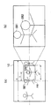
図4(a)は第1撮像部2aおよび撮像回路28aから得られた映像に重畳された、相対的な第2撮像部2bの撮像範囲を示す枠FRを示し、図4(b)は第2撮像部2bの撮像範囲を示す。
FIG. 4A shows a frame FR indicating the relative imaging range of the
第1撮像部2aの光軸L1と第2撮像部2bの光軸L2とは輻輳角αをなし、視差が生じるため、第2撮像部2bの撮像範囲で捉えられた、クロスポイント以外の位置にある被写体が、第1撮像部2aの画像に重畳された枠内の被写体と完全にずれなく一致することはない。
Since the optical axis L1 of the
図4(b)では、第2撮像部2bの撮像範囲で2人の被写体SB1・SB2が捉えられているが、図4(a)では、被写体SB1が枠FRからはみだしている。
In FIG. 4B, two subjects SB1 and SB2 are captured in the imaging range of the
なお、重畳された枠の内側の映像は、第1撮像部2aおよび撮像回路28aから得られた映像でもよいが(図4)、枠の重畳とともに、あるいは枠の重畳に代えて、第2撮像部2bおよび撮像回路28bから得られた映像(第2スルー画)を重畳(はめ込み合成)してもよい(図5)。CPU19は、枠の合成の有無/はめ込み合成の有無を操作部9からの任意の選択操作に応じて切り替えてもよい。
Note that the image inside the superimposed frame may be an image obtained from the
また、枠FRは第2撮像部2bの撮像範囲を示す映像の一例にすぎず、CPU19の指示に応じた表示制御部35やOSD信号発生回路46による当該範囲を示す映像効果の付与、例えば範囲内の第1スルー画の白黒化、点滅、格子その他の所定パターンのマスキングを、枠FRの代わりにあるいは枠FRとともに用いてもよい。
Further, the frame FR is merely an example of an image showing the imaging range of the
図5(a)は第1撮像部2aおよび撮像回路28aから得られた映像に重畳された枠FRと枠FR内に重畳された第2撮像部2bの撮像範囲を示し、図5(b)は第2撮像部2bの撮像範囲を示す。このようなはめ込み合成映像により、広角側の撮像範囲で撮られた画像と望遠側の撮像範囲で撮られた画像の双方を同時に撮影者が確認できる。なお、ここでいう画像とは、典型的には撮影画角の確認を撮影者に行わせるスルー画(第1スルー画、第2スルー画)であるが、第1スルー画および第2スルー画を、記録媒体38に記録済みの第1画像データおよび第2画像データで置換することも可能である。これは事後的な撮影画角の確認に役立つ。
FIG. 5A shows the frame FR superimposed on the video obtained from the
なお、図4・5は、第1撮像部2a、第2撮像部2bを水平にして撮影する「横撮り」を想定しているが、第1撮像部2a、第2撮像部2bを垂直にして撮影する「縦撮り」でも、WaやWbを横幅でなく縦(垂直)方向の長さとすれば同様な撮影範囲の表示が可能である。
4 and 5 assume “horizontal shooting” in which the first
以上のように、カメラ1の表示部10は、広角側の撮像光学系の撮像範囲に対する望遠側の撮像光学系の撮像範囲の大きさと相対的位置を被写体までの距離に応じて正確に表示するので、異なる光学系で広角撮影と望遠撮影を同時に行う場合、双方の画角を把握させやすくし、操作性をよくすることができる。
As described above, the
さらに、本発明は、2つ以上の撮像光学系を有するカメラにおいて、異なる任意の2つの光学系のズーム位置が広角側と望遠側に設定される場合に、一般的に適用できる。 Furthermore, the present invention can be generally applied to a camera having two or more imaging optical systems when the zoom positions of any two different optical systems are set to the wide-angle side and the telephoto side.
2a:第1撮像部、2b:第2撮像部、11:第1ズームレンズ、13:第1フォーカスレンズ、20:第2ズームレンズ、22:第2フォーカスレンズ、29:モータドライバ、19:CPU、45:測距部 2a: first imaging unit, 2b: second imaging unit, 11: first zoom lens, 13: first focus lens, 20: second zoom lens, 22: second focus lens, 29: motor driver, 19: CPU 45: Distance measuring unit
Claims (10)
前記第1の光学系のズーム位置を広角側に設定するとともに、前記第2の光学系のズーム位置を望遠側に設定するズーム調節部と、
被写体までの距離を測定する測距部と、
前記測距部の測定した距離に応じて、前記第1の光学系の撮像範囲における前記第2の光学系の相対的な撮像範囲を決定する範囲決定部と、
前記範囲決定部の決定した前記第2の光学系の相対的な撮像範囲を示す映像を前記第1の第1の光学系の撮像範囲を示す映像に重畳して所定の表示装置に表示するよう制御する制御部と、
を備える撮像装置。 A subject image formed through each of the first optical system and the second optical system is photoelectrically converted by an imaging device, and the first image and the second optical system are images corresponding to the first optical system. An imaging unit capable of outputting a second image that is an image corresponding to
A zoom adjustment unit that sets the zoom position of the first optical system to the wide-angle side and sets the zoom position of the second optical system to the telephoto side;
A distance measuring unit that measures the distance to the subject;
A range determining unit that determines a relative imaging range of the second optical system in an imaging range of the first optical system according to a distance measured by the ranging unit;
An image showing a relative imaging range of the second optical system determined by the range determining unit is superimposed on an image showing the imaging range of the first optical system and displayed on a predetermined display device. A control unit to control;
An imaging apparatus comprising:
D=H×d/Wa
d=SB×(Lx−L)/Lx
Wa≒2×L×tanθa
により決定する請求項1に記載の撮像装置。 The range determining unit is configured to determine a distance D from a center position of an image indicating an imaging range of the first optical system to a center position of an image indicating a relative imaging range of the second optical system, and H is the first position. 1 is a width of an image showing an imaging range of the optical system, L is a distance measured by the distance measuring unit, SB is a base line length, Lx is a distance from the imaging device to a cross point, and θa is a half image of the first optical system. The angle, Wa is the imaging range (width) of the first optical system at the distance L, d is the distance between the optical axes of the first and second optical systems at the distance L, and Lx >> SB, D = H × d / Wa
d = SB × (Lx−L) / Lx
Wa≈2 × L × tan θa
The imaging device according to claim 1, which is determined by:
H’=H×Wb/Wa=H×tanθb/tanθa
により決定する請求項2に記載の撮像装置。 The range determining unit sets a video width H ′ indicating an imaging range of the second optical system on the screen of the predetermined display device, θb is a half angle of view of the second optical system, and Wb is a distance L. H ′ = H × Wb / Wa = H × tan θb / tan θa, assuming that Lx >> SB.
The imaging device according to claim 2, which is determined by:
前記測距部の測定した距離に応じて、前記第1の光学系の撮像範囲における前記第2の光学系の相対的な撮像範囲を決定するステップと、
前記決定した前記第2の光学系の相対的な撮像範囲を示す映像を前記第1の第1の光学系の撮像範囲を示す映像に重畳して所定の表示装置に表示するよう制御するステップと、
を実行する撮像方法。 A subject image formed through each of the first optical system and the second optical system is photoelectrically converted by an imaging device, and the first image and the second optical system are images corresponding to the first optical system. An image pickup unit capable of outputting a second image corresponding to the image and a zoom position of the first optical system are set to a wide angle side, and a zoom position of the second optical system is set to a telephoto side. An imaging apparatus including a zoom adjustment unit and a distance measurement unit that measures a distance to a subject.
Determining a relative imaging range of the second optical system in an imaging range of the first optical system according to a distance measured by the ranging unit;
Controlling to display on the predetermined display device an image showing the determined relative imaging range of the second optical system superimposed on an image showing the imaging range of the first optical system; ,
An imaging method for executing.
Priority Applications (1)
| Application Number | Priority Date | Filing Date | Title |
|---|---|---|---|
| JP2009051138A JP2010206643A (en) | 2009-03-04 | 2009-03-04 | Image capturing apparatus and method, and program |
Applications Claiming Priority (1)
| Application Number | Priority Date | Filing Date | Title |
|---|---|---|---|
| JP2009051138A JP2010206643A (en) | 2009-03-04 | 2009-03-04 | Image capturing apparatus and method, and program |
Publications (1)
| Publication Number | Publication Date |
|---|---|
| JP2010206643A true JP2010206643A (en) | 2010-09-16 |
Family
ID=42967645
Family Applications (1)
| Application Number | Title | Priority Date | Filing Date |
|---|---|---|---|
| JP2009051138A Pending JP2010206643A (en) | 2009-03-04 | 2009-03-04 | Image capturing apparatus and method, and program |
Country Status (1)
| Country | Link |
|---|---|
| JP (1) | JP2010206643A (en) |
Cited By (8)
| Publication number | Priority date | Publication date | Assignee | Title |
|---|---|---|---|---|
| WO2012040463A2 (en) | 2010-09-24 | 2012-03-29 | Microsoft Corporation | Wide angle field of view active illumination imaging system |
| JP2013013050A (en) * | 2011-05-27 | 2013-01-17 | Ricoh Co Ltd | Imaging apparatus and display method using imaging apparatus |
| JP2013106170A (en) * | 2011-11-14 | 2013-05-30 | Sony Corp | Image processing apparatus, control method for image processing apparatus, and program |
| WO2013125298A1 (en) * | 2012-02-23 | 2013-08-29 | Necカシオモバイルコミュニケーションズ株式会社 | Terminal device, image capture system, and image capture method |
| JP2014179958A (en) * | 2013-03-15 | 2014-09-25 | Olympus Corp | Picked-up image display device, imaging system, picked-up image display method, and program |
| EP2807826A4 (en) * | 2012-01-23 | 2015-06-03 | Microsoft Technology Licensing Llc | 3d zoom imager |
| JP2017519461A (en) * | 2015-03-31 | 2017-07-13 | シャオミ・インコーポレイテッド | Method and apparatus for displaying framing information |
| JP2020129716A (en) * | 2019-02-07 | 2020-08-27 | シャープ株式会社 | Electronic device, control program, control device, and control method |
-
2009
- 2009-03-04 JP JP2009051138A patent/JP2010206643A/en active Pending
Cited By (17)
| Publication number | Priority date | Publication date | Assignee | Title |
|---|---|---|---|---|
| US8988508B2 (en) | 2010-09-24 | 2015-03-24 | Microsoft Technology Licensing, Llc. | Wide angle field of view active illumination imaging system |
| EP2619987A2 (en) * | 2010-09-24 | 2013-07-31 | Microsoft Corporation | Wide angle field of view active illumination imaging system |
| KR101833576B1 (en) | 2010-09-24 | 2018-02-28 | 마이크로소프트 테크놀로지 라이센싱, 엘엘씨 | Wide angle field of view active illumination imaging system |
| JP2013544455A (en) * | 2010-09-24 | 2013-12-12 | マイクロソフト コーポレーション | Wide-angle visual field active illumination imaging system |
| EP2619987A4 (en) * | 2010-09-24 | 2014-08-27 | Microsoft Corp | Wide angle field of view active illumination imaging system |
| WO2012040463A2 (en) | 2010-09-24 | 2012-03-29 | Microsoft Corporation | Wide angle field of view active illumination imaging system |
| JP2013013050A (en) * | 2011-05-27 | 2013-01-17 | Ricoh Co Ltd | Imaging apparatus and display method using imaging apparatus |
| JP2013106170A (en) * | 2011-11-14 | 2013-05-30 | Sony Corp | Image processing apparatus, control method for image processing apparatus, and program |
| US9720089B2 (en) | 2012-01-23 | 2017-08-01 | Microsoft Technology Licensing, Llc | 3D zoom imager |
| EP2807826A4 (en) * | 2012-01-23 | 2015-06-03 | Microsoft Technology Licensing Llc | 3d zoom imager |
| JPWO2013125298A1 (en) * | 2012-02-23 | 2015-07-30 | Necカシオモバイルコミュニケーションズ株式会社 | Terminal device, photographing system, and photographing method |
| US9762891B2 (en) | 2012-02-23 | 2017-09-12 | Nec Corporation | Terminal device, image shooting system and image shooting method |
| WO2013125298A1 (en) * | 2012-02-23 | 2013-08-29 | Necカシオモバイルコミュニケーションズ株式会社 | Terminal device, image capture system, and image capture method |
| JP2014179958A (en) * | 2013-03-15 | 2014-09-25 | Olympus Corp | Picked-up image display device, imaging system, picked-up image display method, and program |
| JP2017519461A (en) * | 2015-03-31 | 2017-07-13 | シャオミ・インコーポレイテッド | Method and apparatus for displaying framing information |
| JP2020129716A (en) * | 2019-02-07 | 2020-08-27 | シャープ株式会社 | Electronic device, control program, control device, and control method |
| JP7158307B2 (en) | 2019-02-07 | 2022-10-21 | シャープ株式会社 | ELECTRONIC DEVICE, CONTROL PROGRAM, CONTROL DEVICE, AND CONTROL METHOD |
Similar Documents
| Publication | Publication Date | Title |
|---|---|---|
| JP4787906B1 (en) | Imaging apparatus, method and program | |
| JP5595499B2 (en) | Monocular stereoscopic imaging device | |
| JP5269252B2 (en) | Monocular stereoscopic imaging device | |
| JP5722975B2 (en) | Imaging device, shading correction method for imaging device, and program for imaging device | |
| JP5096048B2 (en) | Imaging apparatus, stereoscopic image reproduction apparatus, and stereoscopic image reproduction program | |
| JP5166650B2 (en) | Stereo imaging device, image playback device, and editing software | |
| JP2011045039A (en) | Compound-eye imaging apparatus | |
| JP5371845B2 (en) | Imaging apparatus, display control method thereof, and three-dimensional information acquisition apparatus | |
| JP5216640B2 (en) | Imaging apparatus and method | |
| JP2010206643A (en) | Image capturing apparatus and method, and program | |
| JP4763827B2 (en) | Stereoscopic image display device, compound eye imaging device, and stereoscopic image display program | |
| JP5415170B2 (en) | Compound eye imaging device | |
| WO2012108099A1 (en) | Imaging device and imaging method | |
| JP2008294530A (en) | Imaging apparatus, image reproducing device, imaging method, image reproducing method, and program | |
| JP2006162990A (en) | Stereoscopic image photographing apparatus | |
| JP2006162991A (en) | Stereoscopic image photographing apparatus | |
| JP2010204483A (en) | Imaging apparatus, method and program | |
| JP4748398B2 (en) | Imaging apparatus, imaging method, and program | |
| JP2010154310A (en) | Compound-eye camera, and photographing method | |
| JP5611469B2 (en) | Stereoscopic imaging apparatus and method | |
| JP2008061259A (en) | Photographing apparatus | |
| JP2012124650A (en) | Imaging apparatus, and imaging method | |
| JP2010147812A (en) | Compound-eye camera, and image processing method | |
| WO2011101928A1 (en) | Three-dimensional image capturing adopter, hybrid image-capturing system, and electronic camera | |
| JP2008046652A (en) | Photographing apparatus |