JP2010144537A - Compressor for fuel cell - Google Patents
Compressor for fuel cell Download PDFInfo
- Publication number
- JP2010144537A JP2010144537A JP2008319988A JP2008319988A JP2010144537A JP 2010144537 A JP2010144537 A JP 2010144537A JP 2008319988 A JP2008319988 A JP 2008319988A JP 2008319988 A JP2008319988 A JP 2008319988A JP 2010144537 A JP2010144537 A JP 2010144537A
- Authority
- JP
- Japan
- Prior art keywords
- rotating shaft
- stator
- electromagnet
- shaft
- axial
- Prior art date
- Legal status (The legal status is an assumption and is not a legal conclusion. Google has not performed a legal analysis and makes no representation as to the accuracy of the status listed.)
- Pending
Links
Images
Classifications
-
- F—MECHANICAL ENGINEERING; LIGHTING; HEATING; WEAPONS; BLASTING
- F16—ENGINEERING ELEMENTS AND UNITS; GENERAL MEASURES FOR PRODUCING AND MAINTAINING EFFECTIVE FUNCTIONING OF MACHINES OR INSTALLATIONS; THERMAL INSULATION IN GENERAL
- F16C—SHAFTS; FLEXIBLE SHAFTS; ELEMENTS OR CRANKSHAFT MECHANISMS; ROTARY BODIES OTHER THAN GEARING ELEMENTS; BEARINGS
- F16C17/00—Sliding-contact bearings for exclusively rotary movement
- F16C17/02—Sliding-contact bearings for exclusively rotary movement for radial load only
- F16C17/024—Sliding-contact bearings for exclusively rotary movement for radial load only with flexible leaves to create hydrodynamic wedge, e.g. radial foil bearings
-
- F—MECHANICAL ENGINEERING; LIGHTING; HEATING; WEAPONS; BLASTING
- F16—ENGINEERING ELEMENTS AND UNITS; GENERAL MEASURES FOR PRODUCING AND MAINTAINING EFFECTIVE FUNCTIONING OF MACHINES OR INSTALLATIONS; THERMAL INSULATION IN GENERAL
- F16C—SHAFTS; FLEXIBLE SHAFTS; ELEMENTS OR CRANKSHAFT MECHANISMS; ROTARY BODIES OTHER THAN GEARING ELEMENTS; BEARINGS
- F16C2360/00—Engines or pumps
- F16C2360/44—Centrifugal pumps
-
- F—MECHANICAL ENGINEERING; LIGHTING; HEATING; WEAPONS; BLASTING
- F16—ENGINEERING ELEMENTS AND UNITS; GENERAL MEASURES FOR PRODUCING AND MAINTAINING EFFECTIVE FUNCTIONING OF MACHINES OR INSTALLATIONS; THERMAL INSULATION IN GENERAL
- F16C—SHAFTS; FLEXIBLE SHAFTS; ELEMENTS OR CRANKSHAFT MECHANISMS; ROTARY BODIES OTHER THAN GEARING ELEMENTS; BEARINGS
- F16C32/00—Bearings not otherwise provided for
- F16C32/04—Bearings not otherwise provided for using magnetic or electric supporting means
- F16C32/0406—Magnetic bearings
- F16C32/044—Active magnetic bearings
- F16C32/0474—Active magnetic bearings for rotary movement
- F16C32/0476—Active magnetic bearings for rotary movement with active support of one degree of freedom, e.g. axial magnetic bearings
-
- F—MECHANICAL ENGINEERING; LIGHTING; HEATING; WEAPONS; BLASTING
- F16—ENGINEERING ELEMENTS AND UNITS; GENERAL MEASURES FOR PRODUCING AND MAINTAINING EFFECTIVE FUNCTIONING OF MACHINES OR INSTALLATIONS; THERMAL INSULATION IN GENERAL
- F16C—SHAFTS; FLEXIBLE SHAFTS; ELEMENTS OR CRANKSHAFT MECHANISMS; ROTARY BODIES OTHER THAN GEARING ELEMENTS; BEARINGS
- F16C35/00—Rigid support of bearing units; Housings, e.g. caps, covers
- F16C35/02—Rigid support of bearing units; Housings, e.g. caps, covers in the case of sliding-contact bearings
Landscapes
- Engineering & Computer Science (AREA)
- General Engineering & Computer Science (AREA)
- Physics & Mathematics (AREA)
- Fluid Mechanics (AREA)
- Mechanical Engineering (AREA)
- Structures Of Non-Positive Displacement Pumps (AREA)
- Support Of The Bearing (AREA)
- Magnetic Bearings And Hydrostatic Bearings (AREA)
- Fuel Cell (AREA)
- Connection Of Motors, Electrical Generators, Mechanical Devices, And The Like (AREA)
Abstract
Description
本発明は、例えば燃料電池自動車等の燃料電池に、水素等と反応させて電力を発生させるための酸素を含む空気を圧縮して供給する燃料電池用圧縮機(過給機)に関するものである。 The present invention relates to a fuel cell compressor (supercharger) that compresses and supplies oxygen-containing air for generating electric power by reacting with hydrogen or the like to a fuel cell such as a fuel cell vehicle. .
近年、水素、アルコール等の燃料を燃焼させずに、燃料電池において電気化学的に空気中の酸素と反応させて電力を発生させ、発生させた電力によって電動機を回転させて走行する燃料電池自動車の開発が進んでいる。燃料電池に空気を供給するためには、電動モータと、前記電動モータの回転軸に連結された遠心圧縮機とを備えた燃料電池用圧縮機が用いられる。 2. Description of the Related Art Recently, fuel cells such as hydrogen and alcohol do not burn, but generate electric power by electrochemically reacting with oxygen in the air in a fuel cell, and a fuel cell vehicle that runs by rotating an electric motor with the generated electric power. Development is progressing. In order to supply air to the fuel cell, a fuel cell compressor including an electric motor and a centrifugal compressor connected to a rotating shaft of the electric motor is used.
前記燃料電池用圧縮機においては、空気を十分に圧縮した状態で燃料電池に供給する必要があるため、遠心圧縮機のインペラをおよそ数万回転以上といった高速で回転させなければならない。そのため電動モータの回転軸を、通常の転がり軸受等ではなく、フォイル軸受や磁気軸受を用いて、高速回転時に非接触の状態で支持する場合がある。
例えば前記回転軸を、ロータを挟んで回転軸の軸方向の両側で、かつステータの両側の端部より軸方向外方の領域に設けた一対のラジアルフォイル軸受によって径方向から支持すると共に、同領域に設けた一対のアキシアル磁気軸受によって軸方向から支持することが行なわれる(例えば特許文献1参照)。
For example, the rotary shaft is supported from the radial direction by a pair of radial foil bearings provided on both sides in the axial direction of the rotary shaft across the rotor and in the axially outer region from the ends on both sides of the stator. Supporting from the axial direction is performed by a pair of axial magnetic bearings provided in the region (see, for example, Patent Document 1).
ラジアルフォイル軸受は、回転軸のうち前記ラジアルフォイル軸受によって支持する部位より大径に形成した通孔の内面に、ごく薄い金属箔等からなる1枚の、または2枚以上のフォイルセグメントを取り付けて構成される。前記ラジアルフォイル軸受によれば、支持する回転軸の回転数が所定値に達するまでは、前記フォイルセグメントが回転軸の外周面に直接に接触して前記回転軸を径方向から支持し、回転数が所定値以上に達した後は、前記回転軸の外周面とフォイルセグメントとの間に発生する動圧によって、回転軸をその全周に亘ってフォイルセグメントの表面から浮上させて、非接触の状態で支持できる。 A radial foil bearing has one or two or more foil segments made of a very thin metal foil attached to the inner surface of a through-hole formed on a rotating shaft having a diameter larger than the portion supported by the radial foil bearing. Composed. According to the radial foil bearing, until the rotational speed of the rotating shaft to support reaches a predetermined value, the foil segment directly contacts the outer peripheral surface of the rotating shaft to support the rotating shaft from the radial direction. After reaching a predetermined value or more, the dynamic pressure generated between the outer peripheral surface of the rotating shaft and the foil segment causes the rotating shaft to float from the surface of the foil segment over the entire circumference, thereby preventing contact Can be supported in a state.
前記ラジアルフォイル軸受には、できるだけ回転数が低い間に速やかに回転軸を浮上できることと、浮上後はできるだけ安定に前記浮上を維持できることが求められる。そのためフォイルセグメントの厚み、形状、枚数等を調整したり、通孔の内径と回転軸の外径との差を調整したりすることが行われる。
しかし一般に、できるだけ低速で速やかに回転軸を浮上できるように特性が調整されたラジアルフォイル軸受は浮上の安定性が低く、逆に回転軸の浮上を安定して維持できるように特性が調整されたラジアルフォイル軸受は、低速域で回転軸を速やかに浮上できないことが多い。
The radial foil bearing is required to be able to float as quickly as possible while the rotational speed is as low as possible, and to maintain the flying as stably as possible after flying. Therefore, the thickness, shape, number, etc. of the foil segments are adjusted, and the difference between the inner diameter of the through hole and the outer diameter of the rotating shaft is adjusted.
However, in general, radial foil bearings whose characteristics have been adjusted so that they can float as quickly as possible at low speeds have low flying stability, and conversely, the characteristics have been adjusted so that the floating shaft can be stably floated. Radial foil bearings are often unable to quickly float the rotating shaft at low speeds.
そのためラジアルフォイル軸受の、回転軸の軸方向の長さ、すなわちフォイルセグメントの同方向の長さを大きくして、前記回転軸の回転時にその外周面とフォイルセグメントとの間で発生する動圧を高めて前記両特性を共に向上することや、あるいはそれぞれの特性に優れたタイプの異なる2つのラジアルフォイル軸受を組み合わせることが検討された。しかしこのいずれの場合にも、ロータの両側の一対のラジアルフォイル軸受を、それぞれ前記長さの長いものやタイプの異なる2つのラジアルフォイル軸受に置換しなければならないため、回転軸の軸長と、前記回転軸を含む燃料電池用圧縮機の回転部分(ロータ、回転軸、遠心圧縮機のインペラ、アキシアル磁気軸受の磁気ディスク等を含む部分)の全長とがこれまでよりも長くなり、それに伴って前記回転部分の固有振動数の低下を招いて、高速回転に十分に適応できなくなるという問題があった。 Therefore, the axial length of the rotary shaft of the radial foil bearing, that is, the length of the foil segment in the same direction is increased, and the dynamic pressure generated between the outer peripheral surface and the foil segment during rotation of the rotary shaft is increased. It has been studied to improve both of the above-mentioned characteristics by combining them, or to combine two different radial foil bearings of different types with excellent characteristics. However, in any of these cases, the pair of radial foil bearings on both sides of the rotor must be replaced with one having a long length or two different radial foil bearings, respectively. The total length of the rotating part of the fuel cell compressor including the rotating shaft (including the rotor, the rotating shaft, the impeller of the centrifugal compressor, the magnetic disk of the axial magnetic bearing, etc.) becomes longer than before. There is a problem in that the natural frequency of the rotating portion is lowered, and it is not possible to sufficiently adapt to high-speed rotation.
本発明の目的は、固有振動数の低下の原因となる回転部分の全長の長大化を生じることなしに、ラジアルフォイル軸受により、電動モータの回転軸をできるだけ低速で速やかに浮上させると共に前記浮上を安定して維持できる燃料電池用圧縮機を提供することにある。 The object of the present invention is to cause the rotary shaft of the electric motor to float as quickly as possible at the lowest possible speed by using a radial foil bearing without causing an increase in the total length of the rotating part that causes a decrease in the natural frequency. An object of the present invention is to provide a compressor for a fuel cell that can be stably maintained.
上記目的を達成するため、本発明は、回転軸(10)、ロータ(11)およびステータ(12)を含む電動モータ(13)と、前記電動モータの回転軸の一端に連結された遠心圧縮機(15)と、前記回転軸を径方向から支持する一対のラジアルフォイル軸受(22)(31)と、前記回転軸を軸方向から支持する一対のアキシアル磁気軸受(24)(33)とを備え、前記ステータはロータが挿通される筒状に形成され、前記ロータは、軸方向の両端部が前記ステータの軸方向の両端部より軸方向内方に凹入させて設けられて、前記ステータ内の軸方向両端部には、回転軸との間にステータの軸方向外方と連通する空間(52)(56)が設けられており、前記一対のラジアルフォイル軸受は、それぞれステータの軸方向外方から、連続するステータ内の空間に亘る領域に設けられていることを特徴とする燃料電池用圧縮機(6)を提供するものである(請求項1)。なお、カッコ内の英数字は後述の実施の形態における対応構成要素等を表す。 To achieve the above object, the present invention provides an electric motor (13) including a rotating shaft (10), a rotor (11) and a stator (12), and a centrifugal compressor connected to one end of the rotating shaft of the electric motor. (15), a pair of radial foil bearings (22) (31) for supporting the rotating shaft from the radial direction, and a pair of axial magnetic bearings (24) (33) for supporting the rotating shaft from the axial direction. The stator is formed in a cylindrical shape through which the rotor is inserted, and the rotor is provided with both axial ends recessed inward in the axial direction from both axial ends of the stator. Spaces (52) and (56) communicating with the axially outer side of the stator are provided between the axially opposite ends of the stator, and the pair of radial foil bearings are respectively arranged outside the axial direction of the stator. From one side There is provided a fuel cell compressor (6), characterized in that provided in the region over the space within the stator (claim 1). The alphanumeric characters in parentheses represent corresponding components in the embodiments described later.
本発明によれば、それぞれステータの両側の端部より軸方向外方の領域だけでなく、前記領域と連続する、ステータの、回転軸との間の空間にもラジアルフォイル軸受を設けることができる。そのため回転軸の軸長、ならびに燃料電池用圧縮機の回転部分の全長を長大化させることなしに、前記ラジアルフォイル軸受として、回転軸の軸方向の長さ、すなわちフォイルセグメントの同方向の長さが大きく、回転軸の回転時に発生する動圧が高いものを用いたり、タイプの異なる2つのラジアルフォイル軸受を用いたりできる。 According to the present invention, the radial foil bearing can be provided not only in the region axially outward from both ends of the stator but also in the space between the stator and the rotating shaft, which is continuous with the region. . Therefore, the axial length of the rotating shaft, that is, the length of the foil segment in the same direction is used as the radial foil bearing without increasing the axial length of the rotating shaft and the total length of the rotating portion of the fuel cell compressor. A large dynamic pressure generated when the rotating shaft rotates or two different radial foil bearings can be used.
したがって本発明によれば、前記軸長および全長の長大化を生じることなく、ラジアルフォイル軸受により、電動モータの回転軸をできるだけ低速で速やかに浮上させると共に前記浮上を安定して維持できる燃料電池用圧縮機を提供することができる。
本発明によれば、アキシアル磁気軸受が、ステータの端部より軸端側に設けられた、回転軸を囲む環状の電磁石(40)(44)と、前記電磁石に軸方向から対向させて回転軸に取り付けられた磁気ディスク(25)(34)とを含む場合に、ラジアルフォイル軸受を、前記電磁石の中心に設けられた通孔(47)(53)に嵌め合わされた第1フォイル軸受(22a)(31a)と、前記第1フォイル軸受と別体に形成され、前記電磁石に固定されてステータ内の空間に挿入された第2フォイル軸受(22b)(31b)とで構成できる(請求項2)。
Therefore, according to the present invention, without increasing the shaft length and the total length, the radial foil bearing allows the rotary shaft of the electric motor to float as quickly as possible and stably maintain the flying. A compressor can be provided.
According to the present invention, the axial magnetic bearing is provided on the shaft end side from the end of the stator, and the annular electromagnets (40) and (44) surrounding the rotating shaft, and the rotating shaft is opposed to the electromagnet in the axial direction. A first foil bearing (22a) fitted with a through-hole (47) (53) provided in the center of the electromagnet when the magnetic disk (25) (34) attached to the magnet is included. (31a) and a second foil bearing (22b) (31b) formed separately from the first foil bearing, fixed to the electromagnet, and inserted into the space in the stator (claim 2). .
この場合、例えば前記第1フォイル軸受および第2フォイル軸受として、それぞれタイプの異なる2つのラジアルフォイル軸受を用いることにより、電動モータの回転軸をできるだけ低速で速やかに浮上させると共に前記浮上を安定して維持することができる。
また両フォイル軸受の特性を同一として、回転軸の軸方向の長さ、すなわちフォイルセグメントの同方向の長さが大きく、回転軸の回転時に発生する動圧が高い一つのラジアルフォイル軸受と同様に機能させることにより、電動モータの回転軸をできるだけ低速で速やかに浮上させると共に前記浮上を安定して維持することもできる。
In this case, for example, by using two radial foil bearings of different types as the first foil bearing and the second foil bearing, the rotating shaft of the electric motor can be floated as quickly as possible and the levitation can be stabilized. Can be maintained.
Also, the characteristics of both foil bearings are the same, the axial length of the rotating shaft, that is, the length of the foil segment in the same direction is large, and the dynamic pressure generated when the rotating shaft rotates is the same as that of one radial foil bearing. By making it function, the rotating shaft of the electric motor can be floated as quickly as possible and at the same time, the flying can be stably maintained.
また本発明によれば、アキシアル磁気軸受が、ステータの端部より軸端側に設けられた、回転軸を囲む環状の電磁石と、前記電磁石に軸端側から対向させて回転軸に取り付けられた磁気ディスクとを含む場合に、ラジアルフォイル軸受を、前記電磁石の中心に設けられた通孔に嵌め合わされた第1部位(31c)と、前記第1部位と一体に形成されてステータ内の空間に挿入された第2部位(31d)とで構成できる(請求項3)。 According to the invention, the axial magnetic bearing is attached to the rotating shaft so as to be opposed to the electromagnet from the shaft end side, which is provided on the shaft end side from the end portion of the stator and surrounds the rotating shaft. In the case of including a magnetic disk, a radial foil bearing is integrally formed with a first hole (31c) fitted in a through hole provided in the center of the electromagnet, and the first part is formed in a space in the stator. It can be comprised with the inserted 2nd site | part (31d) (Claim 3).
この場合、例えば前記両部位を、それぞれタイプの異なる2つのラジアルフォイル軸受として構成することにより、電動モータの回転軸をできるだけ低速で速やかに浮上させると共に前記浮上を安定して維持することができる。
また両部位を連続した一つのラジアルフォイル軸受として構成して、回転軸の軸方向の長さ、すなわちフォイルセグメントの同方向の長さが大きく、回転軸の回転時に発生する動圧が高いものとして機能させることにより、電動モータの回転軸をできるだけ低速で速やかに浮上させると共に前記浮上を安定して維持することもできる。
In this case, for example, by configuring both the parts as two radial foil bearings of different types, the rotating shaft of the electric motor can be floated as quickly as possible and the levitation can be stably maintained.
In addition, both parts are configured as one continuous radial foil bearing, and the axial length of the rotating shaft, that is, the length of the foil segment in the same direction is large, and the dynamic pressure generated when the rotating shaft rotates is high. By making it function, the rotating shaft of the electric motor can be floated as quickly as possible and at the same time, the flying can be stably maintained.
さらに本発明によれば、回転軸の、遠心圧縮機が連結された側と反対側の軸端面に、前記回転軸と同軸となるように雌ねじ穴(62)を設けると共に、磁気ディスクの中心には通孔(64)を設け、ボルト(63)を、前記通孔を挿通させて前記雌ねじ穴に螺合させることにより、前記軸端に磁気ディスクを固定できる(請求項4)。
この場合、前記ボルトの頭部を薄肉化すると共に、例えばアキシアル磁気軸受の電磁石の磁力を制御するために回転軸受の軸方向の位置を検知する変位センサのターゲットとして機能させることができる。そのため燃料電池用圧縮機の回転部分の全長を短縮できる。
Furthermore, according to the present invention, a female screw hole (62) is provided on the shaft end surface of the rotating shaft opposite to the side where the centrifugal compressor is connected so as to be coaxial with the rotating shaft, and at the center of the magnetic disk. The magnetic disk can be fixed to the shaft end by providing a through hole (64) and screwing the bolt (63) into the female screw hole through the through hole (Claim 4).
In this case, the head of the bolt can be thinned, and can function as a target for a displacement sensor that detects the axial position of the rotary bearing, for example, in order to control the magnetic force of the electromagnet of the axial magnetic bearing. Therefore, the total length of the rotating portion of the fuel cell compressor can be shortened.
以下には、図面を参照して、この発明の実施形態について具体的に説明する。
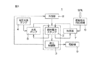
図1は、本発明の燃料電池用圧縮機が組み込まれる、例えば車載用の燃料電池装置の一例を示すブロック図である。
図1を参照して、この例の燃料電池装置1は、燃料電池スタック2と、前記燃料電池スタック2から供給される電力を制御する電力制御器3と、燃料電池スタック2に水素を供給する高圧水素タンク4および水素ポンプ5と、燃料電池スタック2に圧縮空気を供給する燃料電池用圧縮機6と、前記燃料電池用圧縮機6で得られた圧縮空気を加湿する加湿器7と、燃料電池スタック2および電力制御器3を冷却する冷却器8とを備えている。
Embodiments of the present invention will be specifically described below with reference to the drawings.
FIG. 1 is a block diagram showing an example of an in-vehicle fuel cell device in which the fuel cell compressor of the present invention is incorporated.
Referring to FIG. 1, a
前記燃料電池装置1においては、高圧水素タンク4から水素ポンプ5を介して供給された水素と、外部から取り込んだ空気を燃料電池用圧縮機6で圧縮して得られ、加湿器7で加湿された圧縮空気とを燃料電池スタック2に供給する。そして燃料電池スタック2での水素と圧縮空気との電気化学反応によって、電力制御器3で制御された電力によって自動車を走行させる電動機9が駆動される。
In the
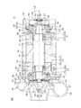
図2は、本発明の一実施形態にかかる燃料電池用圧縮機6の断面図である。
図2を参照して、この例の燃料電池用圧縮機6は、回転軸10、ロータ11およびステータ12を含む電動モータ13と、前記電動モータ13を内部に収容するハウジング14と、前記ハウジング14の一端(図において左端)に結合された遠心圧縮機15とを備えている。ハウジング14は、この実施形態では筒状をなし、その中心軸線L1方向の一端側は前記遠心圧縮機15で閉じられ、他端(図において右端)側は蓋体16で閉じられている。
FIG. 2 is a cross-sectional view of the
Referring to FIG. 2, a
回転軸10は円柱状の軸本体17を有している。ロータ11は、内径が前記軸本体17の外径と一致する筒状をなし、前記軸本体17に外嵌されて、回転軸10と一体回転される。
ステータ12は、外径がハウジング14の内径と一致する筒状をなすステータ本体18を含み、前記ステータ本体18がハウジング14に内嵌されて、前記ハウジング14に固定されている。
The rotating
The
ハウジング14の内周のうち遠心圧縮機15側には、内径がステータ本体18の外径より小さい環状の段部19が設けられていると共に、前記段部19の右端の段差面にステータ本体18の前記遠心圧縮機15側の端面が当接されて前記ステータ本体18、およびステータ12がハウジング14の軸方向に位置決めされている。
ステータ本体18の軸方向両側には、それぞれ筒状をなすステータコイル20、21が突設されている。前記ステータ本体18、およびステータコイル20、21はいずれもロータ11を回転自在に挿通しうる内径を有している。
An
On both sides in the axial direction of the stator
回転軸10の、前記軸本体17より遠心圧縮機15側(図において左側)には、ラジアルフォイル軸受22を構成する第1フォイル軸受22aによって径方向から支持される軸支部23、アキシアル磁気軸受24の磁気ディスク25が取り付けられる取付部26、および遠心圧縮機15のインペラ27が取り付けられる取付部28がこの順に設けられている。前記各部は軸本体17の中心軸線L2と同軸となるように、前記軸本体17と一体形成されている。
From the
軸支部23は軸本体17より小径で、かつ外周面が、低速回転時に第1フォイル軸受22aのフォイルセグメントが周接されると共に回転数が上昇した際に前記フォイルセグメントとの間に動圧を発生させる円筒面とされ、前記第1フォイル軸受22aが外挿されている。
取付部26は前記軸支部23より小径とされて、円盤状の磁気ディスク25の中心に設けられた通孔に嵌め合わされている。
The
The mounting
取付部28は前記取付部26より小径の円柱状とされて、インペラ27の中心の通孔に挿通されている。取付部28の先端には雄ねじ部29が設けられており、前記雄ねじ部29に図示しないナットが螺合されて、インペラ27と磁気ディスク25が回転軸10に固定される。すなわち軸支部23と取付部26との段差面と前記ナットとの間に、スペーサ30等を介してインペラ27と磁気ディスク25が挟まれた状態でナットが締め付けられることにより、前記インペラ27および磁気ディスク25が回転軸10に固定される。
The
回転軸10の、前記軸本体17より蓋体16側(図において右側)には、ラジアルフォイル軸受31を構成する第1フォイル軸受31aによって径方向から支持される軸支部32、およびアキシアル磁気軸受33の磁気ディスク34が取り付けられる取付部35がこの順に設けられている。前記両部は軸本体17の中心軸線L2と同軸となるように、前記軸本体17と一体形成されている。
On the
軸支部32は軸本体17より小径で、かつ外周面が、低速回転時に第1フォイル軸受31aのフォイルセグメントが周接されると共に回転数が上昇した際に前記フォイルセグメントとの間に動圧を発生させる円筒面とされている。
取付部35は前記軸支部32より小径とされて、円盤状の磁気ディスク34の中心に設けられた通孔に嵌め合わされている。
The
The
取付部35の先端には雄ねじ部36が設けられており、前記雄ねじ部36に袋ナット37が螺合されて、磁気ディスク34が回転軸10に固定されている。すなわち軸支部32と取付部35との段差面と前記袋ナット37との間に、スペーサ38を介して磁気ディスク34が挟まれた状態で袋ナット37が締め付けられることにより、前記磁気ディスク34が回転軸10に固定されている。
A
ハウジング14の、遠心圧縮機15側の一端は環状部材39によって構成され、前記環状部材39の環内に、磁気ディスク25と共にアキシアル磁気軸受24を構成する環状の電磁石40が設けられている。
電磁石40は、環状部材39に内嵌された、回転軸10を囲む環状の筐体41内に電磁コイル42を埋設して構成されている。電磁石40は、磁気ディスク25より回転軸10の軸方向の軸本体17側(図において右側、軸方向内方)に設けられており、磁気ディスク25は、前記電磁石40に軸方向外方から対向されている。
One end of the
The electromagnet 40 is configured by embedding an
またハウジング14の、蓋体16側の一端は環状部材43によって構成され、前記環状部材43の環内に、磁気ディスク34と共にアキシアル磁気軸受33を構成する環状の電磁石44が設けられている。
電磁石44は、環状部材43に内嵌された、回転軸10を囲む環状の筐体45内に電磁コイル46を埋設して構成されている。電磁石44は、磁気ディスク34より回転軸10の軸方向の軸本体17側(図において左側、軸方向内方)に設けられており、磁気ディスク34は、前記電磁石44に軸方向外方から対向されている。
One end of the
The
電磁石40の磁気ディスク25に対向する面、および電磁石44の磁気ディスク34に対向する面は、それぞれハウジング14の中心軸線L1に直交する平面とされる。また磁気ディスク25の電磁石40に対向する面、および磁気ディスク34の電磁石44に対向する面は、それぞれ回転軸10の中心軸線L2に直交する平面(ターゲット面)とされている。
The surface of the electromagnet 40 that faces the magnetic disk 25 and the surface of the
磁気ディスク25の電磁石40に対向する面と、磁気ディスク34の電磁石44に対向する面との間の間隔は、前記電磁石40の磁気ディスクに対向する面と、電磁石44の磁気ディスク34に対向する面との間の間隔より、一定のクリアランス分だけ大きめに設定されている。
そのためハウジング14の中心軸線L1と回転軸10の中心軸線L2とが一致した状態(図2の状態)において、両電磁石40、44の電磁コイル42、46に通電して磁力を発生させることにより、回転軸10が、両アキシアル磁気軸受24、33により、軸方向に非接触の状態で支持される。
The space between the surface of the magnetic disk 25 facing the electromagnet 40 and the surface of the
Therefore, in a state where the center axis L1 of the
電磁石40の筐体41は、環の中心の通孔47が、第1フォイル軸受22aの外径と一致する内径を有しており、前記通孔47に第1フォイル軸受22aが内嵌されて保持されている。
すなわち通孔47の遠心圧縮機15側の端部には、径方向内方に突出させて環状の鍔部48が一体形成され、前記鍔部48で囲まれた開口に、通孔47の径方向内方(右方向)から蓋体49が嵌め合わされている。蓋体49の中心には、回転軸10のうちスペーサ30が外嵌された取付部26が回転自在に挿通される通孔が設けられている。
The
That is, an
また筐体41の蓋体16側の端面には蓋体50がネジ止めされて固定されている。この固定状態において、通孔47に内嵌された第1フォイル軸受22aは、その軸方向の両側から蓋体49、50によって挟まれて筐体41に保持されている。蓋体50の中心には、回転軸10のうち軸支部23が挿通される通孔が設けられている。
蓋体49の磁気ディスク25に対向する面は、電磁石40の磁気ディスク25に対抗する面と同一平面とされ、前記面には、前記磁気ディスク25と電磁石40との間の距離、すなわち回転軸10の軸方向の変位量を検知するための変位センサ51が設けられている。
A
The surface of the
蓋体50は、この実施形態では、前記第1フォイル軸受22aと共にラジアルフォイル軸受22を構成する第2フォイル軸受22bと一体形成されている。すなわち蓋体50の蓋体16側の端面に第2フォイル軸受22bが一体に連成されている。
一対のアキシアル磁気軸受24、33によって回転軸10が軸方向から支持された図2の状態において、ロータ11の遠心圧縮機15側の端部は、ステータ12のうちステータコイル20の同じ側の端部より軸方向内方、すなわち図において右方向に凹入させて設けられている。これによりステータコイル20内には、回転軸10の軸本体17のうちロータ11より遠心圧縮機15側の領域との間に外部と連通する空間52が設けられ、前記空間52に第2フォイル軸受22bが挿入されている。
In this embodiment, the
In the state of FIG. 2 in which the
第2フォイル軸受22bは、ステータコイル20の内径よりわずかに小さい外径を有している。また前記軸本体17のうちロータ11より遠心圧縮機15側の領域は、外周面が、低速回転時に第2フォイル軸受22bのフォイルセグメントが周接されると共に回転数が上昇した際に前記フォイルセグメントとの間に動圧を発生させる円筒面とされている。そして空間52に挿入された第2フォイル軸受22bが軸本体17に外挿されて、前記軸本体17が第2フォイル軸受22bによって径方向から支持されている。
The second foil bearing 22 b has an outer diameter that is slightly smaller than the inner diameter of the
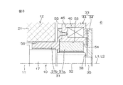
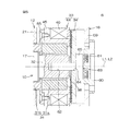
図3は、前記燃料電池用圧縮機のうちラジアルフォイル軸受31、およびアキシアル磁気軸受33による軸支部分を拡大した断面図である。
図2、図3を参照して、アキシアル磁気軸受33を構成する電磁石44の筐体45は、環の中心の通孔53が、ラジアルフォイル軸受31を構成する第1フォイル軸受31aの外径と一致する内径を有しており、前記通孔53に第1フォイル軸受31aが内嵌されて保持されている。
FIG. 3 is an enlarged cross-sectional view of a shaft support portion by the radial foil bearing 31 and the axial
2 and 3, the
すなわち通孔53の蓋体16側の端部には、径方向内方に突出させて環状の鍔部54が一体形成され、筐体45の遠心圧縮機15側の端面には蓋体55がネジ止めされて固定されている。この固定状態において、通孔53に内嵌された第1フォイル軸受31aは、その軸方向の両側から鍔部54、および蓋体55によって挟まれて筐体45に保持されている。蓋体55の中心には、回転軸10のうち軸支部32が挿通される通孔が設けられている。
That is, an
蓋体55は、この実施形態では、前記第1フォイル軸受31aと共にラジアルフォイル軸受31を構成する第2フォイル軸受31bと一体形成されている。すなわち蓋体55の遠心圧縮機15側の端面に第2フォイル軸受31bが一体に連成されている。
一対のアキシアル磁気軸受24、33によって回転軸10が軸方向から支持された図2の状態において、ロータ11の蓋体16側の端部は、ステータ12のうちステータコイル21の同じ側の端部より軸方向内方、すなわち図において左方向に凹入させて設けられている。これによりステータコイル21内には、回転軸10の軸本体17のうちロータ11より蓋体16側の領域との間に外部と連通する空間56が設けられ、前記空間56に第2フォイル軸受22bが挿入されている。
In this embodiment, the
In the state of FIG. 2 in which the
第2フォイル軸受31bは、ステータコイル21の内径よりわずかに小さい外径を有している。また前記軸本体17のうちロータ11より蓋体16側の領域は、外周面が、低速回転時に第2フォイル軸受31bのフォイルセグメントが周接されると共に回転数が上昇した際に前記フォイルセグメントとの間に動圧を発生させる円筒面とされている。そして空間56に挿入された第2フォイル軸受31bが軸本体17に外挿されて、前記軸本体17が第2フォイル軸受31bによって径方向から支持されている。
The second foil bearing 31 b has an outer diameter that is slightly smaller than the inner diameter of the
遠心圧縮機15は、インペラ27と、前記インペラ27の回転に伴って外部から空気を取り込み、圧縮して圧縮空気として送り出すための空気の流路57が設けられたケーシング58とを備えている。
蓋体16は環状をなし、環の一端(図において右端)が鏡板59によって閉じられた形状に一体形成されている。鏡板59の中心には開口が設けられ、前記開口にセンサ保持部材60が嵌め合わされている。
The
The
袋ナット37は、蓋体16側の端面が回転軸10の中心軸線L2に直交する平面(センサターゲット面)とされている。またセンサ保持部材60は、遠心圧縮機15側の面がハウジング14の中心軸線L1に直交する平面とされて、前記袋ナット37の端面と対向されている。前記センサ保持部材60の、袋ナット37の端面と対向する面には変位センサ61が設けられている。変位センサ61は、センサ保持部材60と袋ナット37との間の距離、すなわち回転軸10の軸方向の変位量を検知する。
The end face on the
変位センサ61、および先の変位センサ51によって検知された変位量は図示しない制御部に入力され、前記制御部はこれらの変位量をもとにして、磁気ディスク25と電磁石40との間の距離、および磁気ディスク34と電磁石44との間の距離が一定となるように、電磁コイル42、46への通電量を制御する。
前記実施形態の燃料電池用圧縮機6においては、第1フォイル軸受22a、31aと第2フォイル軸受22b、31bとして、それぞれタイプの異なる2種のラジアルフォイル軸受を用いることができる。
The displacement detected by the
In the
例えばラジアルフォイル軸受22を構成する第1および第2フォイル軸受22a、22bのうちの一方、ならびにラジアルフォイル軸受31を構成する第1および第2フォイル軸受31a、31bのうちの一方を、できるだけ低速で速やかに回転軸を浮上できるように特性が調整されたラジアルフォイル軸受、他方を、回転軸の浮上を安定して維持できるように特性が調整されたラジアルフォイル軸受とすることにより、電動モータ13の回転軸をできるだけ低速で速やかに浮上させると共に前記浮上を安定して維持することができる。
For example, one of the first and
また前記各フォイル軸受22a、22b、31a、31bとして、いずれも同じタイプのラジアルフォイル軸受を用いることもできる。
その場合には、第1および第2フォイル軸受22a、22bを、回転軸10の軸方向の長さ、すなわちフォイルセグメントの同方向の長さが大きく、回転軸10の回転時に発生する動圧が高い一つのラジアルフォイル軸受22として機能させることができる。また第1および第2フォイル軸受31a、31bを、同じく回転軸10の軸方向の長さ、すなわちフォイルセグメントの同方向の長さが大きく、回転軸10の回転時に発生する動圧が高い一つのラジアルフォイル軸受31として機能させることができる。
In addition, as each of the
In this case, the first and
そのため、電動モータの回転軸をできるだけ低速で速やかに浮上させると共に前記浮上を安定して維持することができる。
しかも前記実施形態の燃料電池用圧縮機6においては、前記第2フォイル軸受22b、31bを、電動モータ13のステータ12の両端に設けた空間52、56内に挿入させて配置している。
For this reason, the rotating shaft of the electric motor can be floated as quickly as possible and at the same time the flying can be stably maintained.
Moreover, in the
そのため回転軸10の軸長と、前記回転軸10を含む燃料電池用圧縮機6の回転部分(回転軸10、ロータ11、遠心圧縮機15のインペラ27、アキシアル磁気軸受24、33の磁気ディスク25、34等を含む部分)の全長とが長大化するのを抑制して固有振動数の低下を防止できる。
この発明の実施形態の説明は以上であるが、この発明は、前述の実施形態の内容に限定されるものではなく、請求項記載の範囲内において種々の変更が可能である。なお以下では、図1ないし図3に示す実施の形態と異なる点について主に説明し、同様の構成には同様の符号を付してその説明を省略する。
Therefore, the axial length of the
Although the description of the embodiment of the present invention has been described above, the present invention is not limited to the contents of the above-described embodiment, and various modifications can be made within the scope of the claims. In the following, differences from the embodiment shown in FIGS. 1 to 3 will be mainly described, and the same components are denoted by the same reference numerals, and description thereof will be omitted.
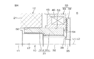
例えば図4に示すようにラジアルフォイル軸受31は一体形成できる。
すなわち図の変形例では、ラジアルフォイル軸受31を、電磁石44の筐体45の、環の中心の通孔53に内嵌されて保持された第1部位31cと、前記第1部位31cの遠心圧縮機15側(図では左側)に一体に連成されてステータ12の蓋体16側(図では右側)の空間56内に挿入された第2部位31dとで一体形成している。
For example, as shown in FIG. 4, the radial foil bearing 31 can be integrally formed.
That is, in the modification shown in the figure, the radial foil bearing 31 is held by being fitted into the through
図示していないがラジアルフォイル軸受22も、同様に電磁石40の筐体41の、環の中心の通孔47に内嵌されて保持される第1部位と、前記第1部位の蓋体16側に一体に連成されてステータ12の遠心圧縮機15側の空間52内に挿入される第2部位とで一体形成できる。
この場合、例えば1つのラジアルフォイル軸受22、31を構成する第1部位と第2部位のうちの一方を、できるだけ低速で速やかに回転軸を浮上できるように特性を調整し、他方を、回転軸の浮上を安定して維持できるように特性を調整することにより、電動モータ13の回転軸をできるだけ低速で速やかに浮上させると共に前記浮上を安定して維持することができる。
Although not shown in the drawings, the radial foil bearing 22 is also a first portion of the
In this case, for example, one of the first part and the second part constituting one radial foil bearing 22, 31 is adjusted so that the rotating shaft can be floated as quickly as possible, and the other is connected to the rotating shaft. By adjusting the characteristics so that the levitation of the
また第1および第2部位の特性を揃えて、ラジアルフォイル軸受22、31を、回転軸10の軸方向の長さ、すなわちフォイルセグメントの同方向の長さが大きく、回転軸10の回転時に発生する動圧が高いものとして機能させることもできる。
しかも第2部位を、電動モータ13のステータ12の両端に設けた空間52、56内に挿入させて配置しているため、回転軸10の軸長と、前記回転軸10を含む燃料電池用圧縮機6の回転部分(回転軸10、ロータ11、遠心圧縮機15のインペラ27、アキシアル磁気軸受24、33の磁気ディスク25、34等を含む部分)の全長とが長大化するのを抑制して固有振動数の低下を防止できる。
In addition, the
In addition, since the second portion is disposed by being inserted into the
また図5に示すように、回転軸10の蓋体16側の構造を変更して、前記軸長および回転部分の全長を短縮することもできる。
すなわち図5の変形例では、回転軸10の蓋体16側(図では右側)の端部を、取付部35および雄ねじ部36を省略した短縮形状として、軸支部32の軸端面に、前記回転軸10の中心軸線L2と同軸となるように雌ねじ穴62を設けている。
Further, as shown in FIG. 5, the structure of the
That is, in the modified example of FIG. 5, the end of the
また磁気ディスク34の中心には、前記雌ねじ穴62に螺合されるボルト63が挿通される通孔64を設けている。そして、前記通孔64を挿通させたボルト63を雌ねじ穴62に螺合させて締め付けることにより、前記磁気ディスク34が、スペーサ38を介して回転軸10の軸端に固定されている。
ボルト63の頭部65は、回転軸10の中心軸線L2に直交する平面(センサターゲット面)とされて、センサ保持部材60の遠心圧縮機15側の面と対向されている。センサ保持部材60の前記面には変位センサ61が設けられている。
At the center of the
The
かかる構造では、ボルト63の頭部65を薄肉化すると共に、前記のように変位センサ61のターゲットとして機能させることができる。そのため袋ナット37を用いる場合に比べて燃料電池用圧縮機6の回転部分の全長を短縮できる。
その他、本発明の燃料電池用圧縮機は、車載用以外の用途に用いることができる。
In such a structure, the
In addition, the fuel cell compressor of the present invention can be used for purposes other than in-vehicle use.
6:燃料電池用圧縮機、10:回転軸、11:ロータ、12:ステータ、13:電動モータ、15:遠心圧縮機、22、31:ラジアルフォイル軸受、22a、31a:第1フォイル軸受、22b、31b:第2フォイル軸受、24、33:アキシアル磁気軸受、25、34:磁気ディスク、31c:第1部位、31d:第2部位、40、44:電磁石、47、53:通孔、52、56:空間、62:雌ねじ穴、63:ボルト、64:通孔。
6: Compressor for fuel cell, 10: Rotating shaft, 11: Rotor, 12: Stator, 13: Electric motor, 15: Centrifugal compressor, 22, 31: Radial foil bearing, 22a, 31a: First foil bearing,
Claims (4)
前記電動モータの回転軸の一端に連結された遠心圧縮機と、
前記回転軸を径方向から支持する一対のラジアルフォイル軸受と、
前記回転軸を軸方向から支持する一対のアキシアル磁気軸受とを備え、
前記ステータはロータが挿通される筒状に形成され、前記ロータは、軸方向の両端部が前記ステータの軸方向の両端部より軸方向内方に凹入させて設けられて、前記ステータ内の軸方向両端部には、回転軸との間にステータの軸方向外方と連通する空間が設けられており、
前記一対のラジアルフォイル軸受は、それぞれステータの軸方向外方から、連続するステータ内の空間に亘る領域に設けられていることを特徴とする燃料電池用圧縮機。 An electric motor including a rotating shaft, a rotor and a stator;
A centrifugal compressor connected to one end of a rotating shaft of the electric motor;
A pair of radial foil bearings for supporting the rotating shaft from a radial direction;
A pair of axial magnetic bearings for supporting the rotating shaft from the axial direction;
The stator is formed in a cylindrical shape through which a rotor is inserted, and the rotor is provided with both axial ends recessed inward in the axial direction from both axial ends of the stator. Spaces communicating with the axially outer side of the stator are provided between the axial ends and the rotating shaft,
The pair of radial foil bearings is provided in a region extending from the outside of the stator in the axial direction to the space in the continuous stator, respectively.
Priority Applications (1)
| Application Number | Priority Date | Filing Date | Title |
|---|---|---|---|
| JP2008319988A JP2010144537A (en) | 2008-12-16 | 2008-12-16 | Compressor for fuel cell |
Applications Claiming Priority (1)
| Application Number | Priority Date | Filing Date | Title |
|---|---|---|---|
| JP2008319988A JP2010144537A (en) | 2008-12-16 | 2008-12-16 | Compressor for fuel cell |
Publications (1)
| Publication Number | Publication Date |
|---|---|
| JP2010144537A true JP2010144537A (en) | 2010-07-01 |
Family
ID=42565229
Family Applications (1)
| Application Number | Title | Priority Date | Filing Date |
|---|---|---|---|
| JP2008319988A Pending JP2010144537A (en) | 2008-12-16 | 2008-12-16 | Compressor for fuel cell |
Country Status (1)
| Country | Link |
|---|---|
| JP (1) | JP2010144537A (en) |
Cited By (10)
| Publication number | Priority date | Publication date | Assignee | Title |
|---|---|---|---|---|
| WO2013028521A1 (en) * | 2011-08-24 | 2013-02-28 | Borgwarner Inc. | Air feed device for a fuel cell |
| KR101507269B1 (en) | 2014-01-21 | 2015-04-07 | 한밭대학교 산학협력단 | Steam compression device which is prevented water condensing |
| CN105257698A (en) * | 2014-07-14 | 2016-01-20 | 张玉宝 | Single-degree-of-freedom magnetic-levitation rotor supporting system and magnetic centering bearing |
| CN105351254A (en) * | 2015-12-09 | 2016-02-24 | 南京磁谷科技有限公司 | Shell of maglev air blower |
| CN105805042A (en) * | 2016-05-05 | 2016-07-27 | 南京磁谷科技有限公司 | Structure for measuring upper and lower displacement quantities of rotor |
| CN106500749A (en) * | 2016-12-19 | 2017-03-15 | 南京磁谷科技有限公司 | A kind of magnetic suspension motor measures the axial sensor supporting structure of rotor |
| CN110821951A (en) * | 2018-08-09 | 2020-02-21 | 博格华纳公司 | Bearing system |
| WO2020196481A1 (en) * | 2019-03-28 | 2020-10-01 | 株式会社豊田自動織機 | Centrifugal compressor for fuel cell |
| CN112821658A (en) * | 2021-03-18 | 2021-05-18 | 上海微电机研究所(中国电子科技集团公司第二十一研究所) | Motor axial traction mechanism based on permanent magnet attraction force and vertical motor |
| JP2021175883A (en) * | 2020-05-01 | 2021-11-04 | 株式会社豊田自動織機 | Fluid machine |
-
2008
- 2008-12-16 JP JP2008319988A patent/JP2010144537A/en active Pending
Cited By (20)
| Publication number | Priority date | Publication date | Assignee | Title |
|---|---|---|---|---|
| WO2013028521A1 (en) * | 2011-08-24 | 2013-02-28 | Borgwarner Inc. | Air feed device for a fuel cell |
| CN103650226A (en) * | 2011-08-24 | 2014-03-19 | 博格华纳公司 | Air feed device for a fuel cell |
| KR101507269B1 (en) | 2014-01-21 | 2015-04-07 | 한밭대학교 산학협력단 | Steam compression device which is prevented water condensing |
| CN105257698A (en) * | 2014-07-14 | 2016-01-20 | 张玉宝 | Single-degree-of-freedom magnetic-levitation rotor supporting system and magnetic centering bearing |
| CN105351254A (en) * | 2015-12-09 | 2016-02-24 | 南京磁谷科技有限公司 | Shell of maglev air blower |
| CN105805042A (en) * | 2016-05-05 | 2016-07-27 | 南京磁谷科技有限公司 | Structure for measuring upper and lower displacement quantities of rotor |
| CN106500749A (en) * | 2016-12-19 | 2017-03-15 | 南京磁谷科技有限公司 | A kind of magnetic suspension motor measures the axial sensor supporting structure of rotor |
| CN110821951A (en) * | 2018-08-09 | 2020-02-21 | 博格华纳公司 | Bearing system |
| JP7140030B2 (en) | 2019-03-28 | 2022-09-21 | 株式会社豊田自動織機 | Centrifugal compressor for fuel cell |
| JP2020165325A (en) * | 2019-03-28 | 2020-10-08 | 株式会社豊田自動織機 | Centrifugal compressor for fuel cell |
| KR20210132170A (en) | 2019-03-28 | 2021-11-03 | 가부시키가이샤 도요다 지도숏키 | Centrifugal Compressors for Fuel Cells |
| CN113614384A (en) * | 2019-03-28 | 2021-11-05 | 株式会社丰田自动织机 | Centrifugal compressor for fuel cell |
| WO2020196481A1 (en) * | 2019-03-28 | 2020-10-01 | 株式会社豊田自動織機 | Centrifugal compressor for fuel cell |
| CN113614384B (en) * | 2019-03-28 | 2023-10-27 | 株式会社丰田自动织机 | Centrifugal compressor for fuel cell |
| US11811108B2 (en) | 2019-03-28 | 2023-11-07 | Kabushiki Kaisha Toyota Jidoshokki | Centrifugal compressor for fuel cell |
| KR102615830B1 (en) * | 2019-03-28 | 2023-12-19 | 가부시키가이샤 도요다 지도숏키 | Centrifugal compressors for fuel cells |
| JP2021175883A (en) * | 2020-05-01 | 2021-11-04 | 株式会社豊田自動織機 | Fluid machine |
| US11441573B2 (en) | 2020-05-01 | 2022-09-13 | Kabushiki Kaisha Toyota Jidoshokki | Fluid machine |
| JP7310698B2 (en) | 2020-05-01 | 2023-07-19 | 株式会社豊田自動織機 | Fluid machinery |
| CN112821658A (en) * | 2021-03-18 | 2021-05-18 | 上海微电机研究所(中国电子科技集团公司第二十一研究所) | Motor axial traction mechanism based on permanent magnet attraction force and vertical motor |
Similar Documents
| Publication | Publication Date | Title |
|---|---|---|
| JP2010144537A (en) | Compressor for fuel cell | |
| US8376722B2 (en) | Electric compressor | |
| US8772992B2 (en) | Airfoil-magnetic hybrid bearing and a control system thereof | |
| JP4788351B2 (en) | Fuel cell supercharger | |
| US20070069597A1 (en) | Fuel-cell compressed-air supplying device | |
| US20090009017A1 (en) | Bearing apparatus and centrifugal compressor provided with same | |
| KR20090007526A (en) | Turbomachine | |
| JP5168587B2 (en) | Bearing device and fuel cell compressor | |
| JP2012500953A (en) | Thrust foil bearing | |
| EP3542079B1 (en) | Thrust active magnetic bearing for shaft slow roll control | |
| JP2008232289A (en) | Bearing device, and rotation driving device having the same | |
| CN108716480A (en) | A kind of magnetic suspension structure and wind turbine | |
| JP2010168904A (en) | Air supply device for fuel cell | |
| JP2020033875A (en) | Compression device | |
| JP2020046006A (en) | Foil bearing | |
| JP2021175883A (en) | Fluid machine | |
| JP2011214404A (en) | Electric compressor | |
| JP5174069B2 (en) | Centrifugal compressor | |
| JP2007247619A (en) | Compressor for fuel cell | |
| JP2850342B2 (en) | Bearing device | |
| JP2020058194A (en) | Rotary electric machine | |
| JP2020007989A (en) | Compression device | |
| JP2009281214A (en) | Centrifugal compressor | |
| JP2007270648A (en) | Compressor for fuel cell | |
| JP4788352B2 (en) | Fuel cell supercharger |