JP2010143048A - Liquid droplet jetting head and liquid droplet jetting device - Google Patents
Liquid droplet jetting head and liquid droplet jetting device Download PDFInfo
- Publication number
- JP2010143048A JP2010143048A JP2008322133A JP2008322133A JP2010143048A JP 2010143048 A JP2010143048 A JP 2010143048A JP 2008322133 A JP2008322133 A JP 2008322133A JP 2008322133 A JP2008322133 A JP 2008322133A JP 2010143048 A JP2010143048 A JP 2010143048A
- Authority
- JP
- Japan
- Prior art keywords
- liquid
- nozzle
- flow path
- suction
- droplet discharge
- Prior art date
- Legal status (The legal status is an assumption and is not a legal conclusion. Google has not performed a legal analysis and makes no representation as to the accuracy of the status listed.)
- Pending
Links
- 239000007788 liquid Substances 0.000 title claims abstract description 204
- 238000007664 blowing Methods 0.000 claims description 16
- 239000002904 solvent Substances 0.000 claims description 8
- 238000001914 filtration Methods 0.000 claims description 7
- 238000007599 discharging Methods 0.000 claims description 6
- 239000010408 film Substances 0.000 description 16
- 238000005452 bending Methods 0.000 description 7
- 239000010409 thin film Substances 0.000 description 6
- 238000001035 drying Methods 0.000 description 5
- 239000000428 dust Substances 0.000 description 4
- 230000005499 meniscus Effects 0.000 description 4
- 230000007423 decrease Effects 0.000 description 3
- 238000005530 etching Methods 0.000 description 3
- 238000004519 manufacturing process Methods 0.000 description 3
- 230000000149 penetrating effect Effects 0.000 description 3
- 229920001721 polyimide Polymers 0.000 description 3
- 238000009423 ventilation Methods 0.000 description 3
- 238000011109 contamination Methods 0.000 description 2
- 238000011049 filling Methods 0.000 description 2
- 238000000034 method Methods 0.000 description 2
- 230000010349 pulsation Effects 0.000 description 2
- 230000000717 retained effect Effects 0.000 description 2
- 239000004593 Epoxy Substances 0.000 description 1
- 239000004642 Polyimide Substances 0.000 description 1
- 238000013459 approach Methods 0.000 description 1
- 230000000740 bleeding effect Effects 0.000 description 1
- 230000006835 compression Effects 0.000 description 1
- 238000007906 compression Methods 0.000 description 1
- 238000013461 design Methods 0.000 description 1
- 238000002474 experimental method Methods 0.000 description 1
- 239000011521 glass Substances 0.000 description 1
- 238000000608 laser ablation Methods 0.000 description 1
- 239000000203 mixture Substances 0.000 description 1
- 230000003287 optical effect Effects 0.000 description 1
- 239000000049 pigment Substances 0.000 description 1
- 229920006254 polymer film Polymers 0.000 description 1
- 230000002265 prevention Effects 0.000 description 1
- 238000012545 processing Methods 0.000 description 1
- 239000011347 resin Substances 0.000 description 1
- 229920005989 resin Polymers 0.000 description 1
- 238000010008 shearing Methods 0.000 description 1
- 229910000679 solder Inorganic materials 0.000 description 1
- 239000000758 substrate Substances 0.000 description 1
- 230000001629 suppression Effects 0.000 description 1
- 230000008961 swelling Effects 0.000 description 1
- XLYOFNOQVPJJNP-UHFFFAOYSA-N water Substances O XLYOFNOQVPJJNP-UHFFFAOYSA-N 0.000 description 1
- 238000009736 wetting Methods 0.000 description 1
Images

Classifications
-
- B—PERFORMING OPERATIONS; TRANSPORTING
- B41—PRINTING; LINING MACHINES; TYPEWRITERS; STAMPS
- B41J—TYPEWRITERS; SELECTIVE PRINTING MECHANISMS, i.e. MECHANISMS PRINTING OTHERWISE THAN FROM A FORME; CORRECTION OF TYPOGRAPHICAL ERRORS
- B41J2/00—Typewriters or selective printing mechanisms characterised by the printing or marking process for which they are designed
- B41J2/005—Typewriters or selective printing mechanisms characterised by the printing or marking process for which they are designed characterised by bringing liquid or particles selectively into contact with a printing material
- B41J2/01—Ink jet
- B41J2/135—Nozzles
- B41J2/14—Structure thereof only for on-demand ink jet heads
-
- B—PERFORMING OPERATIONS; TRANSPORTING
- B41—PRINTING; LINING MACHINES; TYPEWRITERS; STAMPS
- B41J—TYPEWRITERS; SELECTIVE PRINTING MECHANISMS, i.e. MECHANISMS PRINTING OTHERWISE THAN FROM A FORME; CORRECTION OF TYPOGRAPHICAL ERRORS
- B41J2202/00—Embodiments of or processes related to ink-jet or thermal heads
- B41J2202/01—Embodiments of or processes related to ink-jet heads
- B41J2202/07—Embodiments of or processes related to ink-jet heads dealing with air bubbles
-
- B—PERFORMING OPERATIONS; TRANSPORTING
- B41—PRINTING; LINING MACHINES; TYPEWRITERS; STAMPS
- B41J—TYPEWRITERS; SELECTIVE PRINTING MECHANISMS, i.e. MECHANISMS PRINTING OTHERWISE THAN FROM A FORME; CORRECTION OF TYPOGRAPHICAL ERRORS
- B41J2202/00—Embodiments of or processes related to ink-jet or thermal heads
- B41J2202/01—Embodiments of or processes related to ink-jet heads
- B41J2202/12—Embodiments of or processes related to ink-jet heads with ink circulating through the whole print head
Landscapes
- Particle Formation And Scattering Control In Inkjet Printers (AREA)
Abstract
Description
本発明は液滴吐出ヘッドおよび液滴吐出装置に関し、特に高粘度の液を液滴として吐出する液滴吐出ヘッドおよび液滴吐出装置に関する。 The present invention relates to a droplet discharge head and a droplet discharge device, and more particularly to a droplet discharge head and a droplet discharge device that discharge high-viscosity liquid as droplets.
液滴吐出装置として知られている現在市販されている水性インクジェットプリンターは、概ね粘度5cps前後、高々10cpsオーダの染料液や顔料インクを採用している。媒体に着弾した際の液滲み防止や、光学的な色濃度アップ、含水量低減による媒体の膨潤抑制/短時間乾燥、あるいは、そうした高品質液をトータル設計するに当たり自由度が大きくとれる等の理由から、インク粘度を増加することによってプリント性能は向上できることが知られている。 A currently marketed aqueous inkjet printer known as a droplet discharge device employs a dye solution or pigment ink having a viscosity of about 5 cps or so and an order of 10 cps at most. Reasons such as prevention of liquid bleeding when landing on the medium, increase in optical color density, suppression of swelling / short time drying of the medium due to reduced water content, or greater freedom in total design of such high quality liquid Therefore, it is known that the printing performance can be improved by increasing the ink viscosity.
本願発明者らは、梁に圧縮と回転運動を与え、座屈曲げ方向が反転する際の急峻な上下運動を利用して、ノズルから高粘度液滴を所望の方向に慣性離脱させる液滴吐出ヘッドを先に出願した(特許文献1〜4参照)。 The inventors of the present application have applied a compressive and rotational motion to the beam, and a droplet discharge that causes a high-viscosity droplet to inertially release from the nozzle in a desired direction using the steep vertical motion when the seat bending direction is reversed. The head was filed earlier (see Patent Documents 1 to 4).
ところで、高粘度液の吐出においては、低粘度液と比べ吐出滴の安定性が下がる、ノズル毎の吐出液滴のバラツキが大きくなる等の課題が生じやすい。特に高粘度液の過大な流路抵抗に対抗してノズル近傍まで液体を供給するため背圧を付与する場合、ノズルからの液ダレを含めメニスカスの均一維持が更に難しくなり、上記の課題は助長される。 By the way, in the discharge of a high-viscosity liquid, problems such as a decrease in the stability of the discharge droplets and a large variation in discharge droplets from nozzle to nozzle are likely to occur compared to a low-viscosity liquid. In particular, when applying back pressure to supply liquid to the vicinity of the nozzle against the excessive flow resistance of high-viscosity liquid, it becomes more difficult to maintain a uniform meniscus including liquid sag from the nozzle. Is done.
本願発明者の実験によれば、上記課題を解決する方法として、ノズル近傍に液体を拘束しない液溜まりを設け、流路を介して過剰に供給された液体を保持し、且つ過剰な、あるいは余剰となった液体を排出するための吸引排出流路を設ける方法が有効であることが分かった。 According to the experiments of the present inventor, as a method for solving the above problem, a liquid reservoir that does not restrain the liquid is provided in the vicinity of the nozzle, the liquid supplied excessively through the flow path is retained, and an excessive or excessive amount is retained. It has been found that a method of providing a suction / discharge channel for discharging the liquid is effective.
本発明の目的は、梁に圧縮と回転運動を与え、座屈曲げ方向が反転する際の急峻な上下運動を利用して、背圧を印加した高粘度な液をノズルから安定に吐出できる液滴吐出ヘッドを提供することである。
本発明は上記事実を考慮し、背圧を印加した高粘度な液を安定に吐出できる液滴吐出ヘッドおよび液滴吐出装置を提供することを目的とする。 In consideration of the above facts, an object of the present invention is to provide a droplet discharge head and a droplet discharge device that can stably discharge a high-viscosity liquid to which a back pressure is applied.
請求項1に記載の液滴吐出ヘッドは、液滴を吐出するノズルと、前記ノズルに向けて液体が供給される液体流路部材と、前記ノズルに向けて前記液体流路部材中の前記液体に背圧を印加する背圧発生手段と、前記液体流路部材と接合もしくは液体流路部材を含み、液滴吐出面に凹となるように座屈反転変形した後、液滴吐出方向に凸となるよう座屈反転変形し、前記ノズル近傍の液体に吐出方向の慣性を与えることにより、前記ノズル近傍の液を液滴として前記ノズルより吐出させる梁部材と、前記液体流路部材の吐出方向反対側に設けられ大気と連通した開口と、吸引口が前記ノズルの近傍に向いた吸引路と、前記吸引路に負圧を発生させる負圧発生手段と、を備えたことを特徴とする。 The droplet discharge head according to claim 1, wherein a nozzle for discharging droplets, a liquid channel member to which liquid is supplied toward the nozzle, and the liquid in the liquid channel member toward the nozzle Including back pressure generating means for applying back pressure to the liquid flow path member and the liquid flow path member, or buckling and reversing deformation so as to be concave on the liquid drop discharge surface, and then protruding in the liquid drop discharge direction. A beam member that discharges the liquid in the vicinity of the nozzle as a droplet from the nozzle as a liquid droplet, and the discharge direction of the liquid flow path member. An opening provided on the opposite side and communicating with the atmosphere, a suction path whose suction port faces the vicinity of the nozzle, and negative pressure generating means for generating a negative pressure in the suction path are provided.
請求項2に記載の液滴吐出ヘッドは、請求項1に記載の構成において、前記開口は前記液体流路部材の吐出方向厚さよりも薄い柔膜で封止されたことを特徴とする。 According to a second aspect of the present invention, in the liquid droplet ejection head according to the first aspect, the opening is sealed with a soft film thinner than the thickness of the liquid flow path member in the ejection direction.
請求項3に記載の液滴吐出ヘッドは、請求項1または請求項2に記載の構成において、吐出方向より見た前記開口の中心は、前記ノズルの中心よりも前記吸引路側にオフセットしていることを特徴とする。 According to a third aspect of the present invention, in the configuration of the first or second aspect, the center of the opening viewed from the ejection direction is offset to the suction path side than the center of the nozzle. It is characterized by that.
請求項4に記載の液滴吐出ヘッドは、請求項3に記載の構成において、吐出方向より見て前記開口の前記吸引路側端は前記ノズル中心より前記ノズル径の3倍〜10倍の距離範囲にあり、前記吸引路より遠い側端は前記ノズル中心より前記ノズル径の3倍以内の距離範囲にあることを特徴とする。 According to a fourth aspect of the present invention, in the liquid droplet ejection head according to the third aspect, the suction path side end of the opening is a distance range of 3 to 10 times the nozzle diameter from the nozzle center when viewed from the ejection direction. The side end far from the suction path is in a distance range within three times the nozzle diameter from the nozzle center.
請求項5に記載の液滴吐出ヘッドは、請求項1〜請求項4の何れか1項に記載の構成において、前記吸引路の前記吸引口へ空気を送る送風路と、前記送風路に正圧を発生させる送風手段と、前記送風路に設けられ前記空気を濾過する濾過手段と、を備えたことを特徴とする。 According to a fifth aspect of the present invention, in the configuration according to any one of the first to fourth aspects, the liquid droplet ejection head according to the first aspect includes a blower passage that sends air to the suction port of the suction passage, and a positive passage to the blower passage. It is provided with the ventilation means which generates a pressure, and the filtration means which is provided in the said ventilation path and filters the said air.
請求項6に記載の液滴吐出ヘッドは、請求項5に記載の構成において、前記空気に前記液体の溶媒を添加する加湿手段を備えたことを特徴とする。 According to a sixth aspect of the present invention, in the configuration of the fifth aspect, the liquid droplet ejection head includes a humidifying unit that adds the liquid solvent to the air.
請求項7に記載の液滴吐出装置は、請求項1〜請求項6の何れか1項に記載の液滴吐出ヘッドを備えたことを特徴とする。 According to a seventh aspect of the present invention, there is provided a liquid droplet ejection apparatus including the liquid droplet ejection head according to any one of the first to sixth aspects.
請求項1に記載の液滴吐出ヘッドの構成によれば、本構成を有していない場合と比較して、開口に液溜まりが形成され余剰の液は吸引路に吸引されることで、背圧を印加した高粘度な液を安定に吐出できる液滴吐出ヘッドとすることができる。 According to the configuration of the droplet discharge head of the first aspect, compared to the case where the configuration is not provided, a liquid pool is formed in the opening, and excess liquid is sucked into the suction path, thereby A liquid droplet ejection head capable of stably ejecting a highly viscous liquid to which pressure is applied can be obtained.
請求項2に記載の液滴吐出ヘッドの構成によれば、本構成を有していない場合と比較して、液を拘束せず吐出時の抵抗が少ない柔膜で開口からの異物混入や液の乾燥を防止できる液滴吐出ヘッドとすることができる。
According to the configuration of the liquid droplet ejection head according to
請求項3に記載の液滴吐出ヘッドの構成によれば、本構成を有していない場合と比較して、開口の供給側端がノズルから遠すぎることによる液充填効率低下や、開口の吸引側端がノズルに近すぎることによるノズル液膜(メニスカス)の薄化、脈動変動を抑制することができる。 According to the configuration of the droplet discharge head according to claim 3, compared with the case where the present configuration is not provided, the liquid filling efficiency decreases due to the supply side end of the opening being too far from the nozzle, and the suction of the opening Thinning of the nozzle liquid film (meniscus) and pulsation fluctuation due to the side end being too close to the nozzle can be suppressed.
請求項4に記載の液滴吐出ヘッドの構成によれば、本構成を有していない場合と比較して、開口の供給側端がノズルから遠すぎることによる液充填効率低下や、開口の吸引側端がノズルに近すぎることによるノズル液膜(メニスカス)の薄化、脈動変動を抑制することができる。 According to the configuration of the droplet discharge head according to claim 4, compared with the case where the present configuration is not provided, the liquid filling efficiency decreases due to the supply side end of the opening being too far from the nozzle, and the suction of the opening Thinning of the nozzle liquid film (meniscus) and pulsation fluctuation due to the side end being too close to the nozzle can be suppressed.
請求項5に記載の液滴吐出ヘッドの構成によれば、本構成を有していない場合と比較して、送風することにより、ノズル近傍の液にゴミが混入することを防止でき、吸引口からノズル近傍のゴミや残留液の吸引を容易にすることができる。 According to the configuration of the droplet discharge head according to claim 5, it is possible to prevent dust from being mixed into the liquid in the vicinity of the nozzle by blowing air as compared with the case where the present configuration is not provided, and the suction port Therefore, it is possible to easily suck dust and residual liquid in the vicinity of the nozzle.
請求項6に記載の液滴吐出ヘッドの構成によれば、本構成を有していない場合と比較して、空気に液体の溶媒を添加することにより、ノズル近傍の液の乾燥を抑制することができる。 According to the configuration of the droplet discharge head according to the sixth aspect of the present invention, the drying of the liquid in the vicinity of the nozzle is suppressed by adding a liquid solvent to the air as compared with the case where the present configuration is not provided. Can do.
請求項7に記載の液滴吐出装置の構成によれば、本構成を有していない場合と比較して、背圧を印加した高粘度な液を安定に吐出できる液滴吐出装置とすることができる。 According to the configuration of the droplet discharge device of the seventh aspect, the droplet discharge device can stably discharge a high-viscosity liquid to which a back pressure is applied, as compared with the case where the configuration is not provided. Can do.
<基本構成>
図1には、本発明の実施形態に係る液滴吐出ヘッドの基本構造が示されている。
<Basic configuration>
FIG. 1 shows a basic structure of a droplet discharge head according to an embodiment of the present invention.
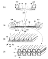
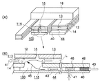
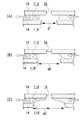
図1(A)、(B)、(C)に示すように液滴吐出ヘッド10は、内部に液流路13を備え長さ方向略中央にノズル16を備えた中空チューブ状の流路部材12と、流路部材12を支持する梁部材14とが柱状に接合され、両端を支持部材18が支持する構造となっている。
As shown in FIGS. 1 (A), (B), and (C), the
また梁部材14にはピエゾ素子30が接合され、さらにピエゾ素子30には信号電極32が接合され梁部材14、ピエゾ素子30、信号電極32でアクチュエータ36を構成している。梁部材14はピエゾ素子30の共通電極を兼ねており、梁部材14と信号電極32とでピエゾ素子30を挟む構造となっている。信号電極32の一方の端には電極パッド33が設けられ、配線34にて図示しないスイッチングICと接続されている。このスイッチングICからの信号によりピエゾ素子30は駆動され、梁部材14を撓ませるか撓ませないかの制御が行われる。
A
流路部材12は、液滴吐出方向(図中上)および逆方向に撓み可能であり、液溜まり24から供給され液流路13を通ってノズル16まで達した液Lを、慣性によって吐出方向に液滴として吐出する。
The
このとき、一方の回転エンコーダ20Aに設けられた液溜まり24からは図示しない背圧発生手段により背圧を印加された液Lが液流路13に供給され、長手方向端よりノズル16近傍まで給送され、ノズル16より液滴2として吐出される。
At this time, the liquid L to which the back pressure is applied by the back pressure generating means (not shown) is supplied from the
さらに図1(B)に示すようにノズル16の反吐出方向では梁部材14およびアクチュエータ36に開口116が設けられ、大気中に開放された構成とされている。これにより液流路13より給送された液Lは、梁部材14に設けられた開口116の近傍で形成された液溜まり100に一時的に滞留する。
Further, as shown in FIG. 1B, an
図1(C)に示すように、他方の回転エンコーダ20Bに設けられた液吸引プール124は図示しない吸引手段と連通し、負圧を印加される。ノズル16を挟んで長手方向反対側の流路部材12には吸引路42が設けられ、液吸引プール124と連通している。このため吸引路42は開口116近傍の液溜まり100に滞留する液Lを逐次吸引、除去する。
As shown in FIG. 1C, the
図1(D)に示すように、梁部材14の一方の側、例えば反吐出方向側には流路部材40が設けられ、内部には送風路44が形成されている。送風路44は図示しない送風手段と連通し、加圧された空気が給送される。このとき送風路44内にフィルタが設けられ空気を濾過する構成でもよく、あるいは加湿手段が設けられ空気を液Lの溶媒成分で加湿する構成とされていてもよい。
As shown in FIG. 1D, a
支持部材18は回転エンコーダ20の回転中心からオフセットされた位置にて両側から押圧され、あるいは曲げ方向に力が加えられインク液吐出方向あるいは逆方向に梁部材14と接合した流路部材12を撓ませる。支持部材18は、例えば図1(A)の紙面前後方向に長い棒状でもよく、支持部材18に複数の流路部材12が設けられた梯子状の構造であってもよい。
The
また、複数のノズル16から一括して液滴2を噴射する液滴吐出ヘッドの場合、吸引路42はノズル16毎に設ける必要はなく、例えば2本のノズル16(液流路13)に対して1本形成してもよい。液流路13と吸引路42とは同形状である必要はなく、吸引路42が液流路13よりも断面が広い(太い/幅広い/高い)構成であってもよい。
Further, in the case of a droplet discharge head that ejects
<座屈反転吐出>
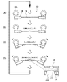
図2および図3には本発明に係る液滴吐出ヘッドの梁部材あるいは流路部材の撓み方向と座屈反転の関係が示されている。両図とも、支持部材に複数の流路部材が梯子状に設けられた構造の液滴吐出ヘッドにおいて、その中の1本の流路部材に注目して変形の様子を表したものである。
<Buckling reversal discharge>
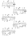
2 and 3 show the relationship between the bending direction of the beam member or flow path member of the droplet discharge head according to the present invention and the buckling reversal. In both figures, in a droplet discharge head having a structure in which a plurality of flow path members are provided on a support member in a ladder shape, the state of deformation is shown paying attention to one of the flow path members.
液滴2を吐出しないように制御された場合、まず図2(A)のように回転エンコーダ20が逆回転(流路部材12を引き伸ばす方向へ回転)し、初期状態では吐出方向へ凸形状となっている流路部材12を真っ直ぐに伸ばす。
When control is performed so as not to eject the
次いで図2(B)のように、流路部材12の伸びを緩めると、流路部材12に吐出を指示する信号が送られないためアクチュエータ36が駆動されず、吐出方向に凸となるように撓んだ状態のままとなる。
Next, as shown in FIG. 2B, when the extension of the
さらに図2(C)および図2(D)で回転エンコーダ20を吐出方向に正回転させ続けると、吐出方向に凸となるように撓んだ状態のまま撓み量が増大してゆくが、座屈反転による流路部材12の吐出方向への変形が起こらないため、ノズル16より液滴2の吐出には至らない。
2C and 2D, if the
これに対して液滴2を吐出するように液滴吐出ヘッド10が制御された場合、まず図3(A)のように回転エンコーダ20が反転(流路部材12を引き伸ばす方向へ回転)し、初期状態では吐出方向へ凸形状となっている流路部材12を真っ直ぐに伸ばし、撓みのない状態とする。
On the other hand, when the
次いで図3(B)のように流路部材12に吐出を指示する信号が図示しないスイッチングICより送られてアクチュエータ36が駆動され、吐出方向に凹となるように撓んだ状態となる。
Next, as shown in FIG. 3B, a signal for instructing ejection to the
さらに図3(C)で回転エンコーダ20を図中矢印方向に正回転させると、流路部材12は回転エンコーダ20に近い方、すなわち長手方向両端側から次第に吐出方向(図中上)に凸へと撓み方向が変化する。
Further, when the
この変化が両端から中央に近付くと、流路部材12(あるいは梁部材14)はある点で急峻な座屈反転を起こし、図3(D)に示すように液滴吐出方向(図中上)へと急激に変形する。 When this change approaches the center from both ends, the flow path member 12 (or the beam member 14) undergoes a steep buckling reversal at a certain point, and as shown in FIG. Deforms rapidly.
流路部材12の長さ方向略中央にはノズル16が設けられているため、流路部材12内部を給送されノズル16まで達している液Lはこの座屈反転による流路部材12の吐出方向への変形に伴い、ノズル16から液滴2として吐出される。
Since the
さらに図3(D)で撓み量が最大となり回転エンコーダ20が停止したのち、逆回転して流路部材12を平坦にする(図3(A))ことで流路部材12は初期位置図3(A)へ復帰する。
Further, in FIG. 3D, after the amount of bending becomes maximum and the
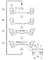
図4には本実施形態に係る液滴吐出ヘッドの、他の構造が示されている。すなわち、梁部材14の長手方向一端を回転エンコーダ20に保持された支持部材18に固定され、長手方向他端は固定端として、固定された支持部材18Bに保持されている。
FIG. 4 shows another structure of the droplet discharge head according to the present embodiment. That is, one end in the longitudinal direction of the
また梁部材14に設けられた流路部材12には支持部材18B側より液流路13が設けられており、長手方向中央近傍に設けられたノズル16に向けて液Lが給送され、ノズル16より吐出される。
The
図4(A)に示すように梁部材14の回転エンコーダ20側半分を吐出側に凹、他端側半分を吐出側に凸とした初期状態より、図4(B)に示すように梁部材14(流路部材12)の端より液Lが液流路13内を給送され、ノズル16へ給送される。
From the initial state in which the half of the
さらに図4(C)に示すように回転エンコーダ20が吐出方向に回転すると支持部材18によって保持されている梁部材14の一端より、吐出方向に凸となるように変形し始め、図4(D)に示すようにノズル16近傍(長手方向中央付近)が吐出方向に座屈反転し、ノズル16より液Lは液滴2として吐出される。
Further, as shown in FIG. 4C, when the
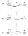
図5(A)、(B)には本発明の第1実施形態に係る液滴吐出ヘッドのノズル近傍における構造の詳細が示されている。 5A and 5B show details of the structure in the vicinity of the nozzle of the droplet discharge head according to the first embodiment of the present invention.
流路部材12によって形成された液流路13内を、背圧を印加された状態で液Lが給送されるため、開口116近傍で形成される液溜まり100には液Lが常に供給される。このとき、液溜まり100は供給不足とならないように吐出で失われる液量よりも多量に供給される液Lを一時的に保持し、余剰分の液Lは負圧を印加された吸引路113にて吸引、排出される。これにより溜まり100の液Lは自由表面を形成し、液滴2の慣性吐出を阻害する液Lの剪断抵抗などは抑制され、反吐出方向(ノズル背面)が密閉された構造と比較して液Lが高粘度であっても吐出を阻害しにくい構成とされる。
Since the liquid L is fed through the
図5(A)、(B)に示すように液滴吐出ヘッド10の流路部材12は、内部長手方向に貫通した液流路13と、流路部材12に設けられたノズル16とを備え、ノズル16の裏側(反吐出方向側)には梁部材14を穿孔した開口116が設けられている。
As shown in FIGS. 5A and 5B, the
梁部材14の反吐出方向(裏側)には流路部材40が設けられ、梁部材14との間には送風路44が形成されている。送風路44は図示しない送風手段と連通し、加圧された空気が矢印43のように給送される。
A
送風路44内には濾過手段としてフィルタ48が設けられ、給送される空気を濾過する。さらに送風路44内には液体を含有可能なスポンジなどの加湿手段46が設けられ、給送される空気を液Lの溶媒成分で加湿する構成とされている。矢印43のように給送された空気の一部は、液溜まり100で矢印45のように吸引路113へ向かい、矢印41のように余剰の液Lと共に吸引除去される。
A
この構成とすることにより、液溜まり100を大気中に開放する構成と比較して、フィルタ48で濾過された空気が液溜まり100に給送されるため、ゴミや異物の混入が少なく、且つ溶媒で加湿された空気が給送されるためノズル16近傍の液Lが乾燥しにくい構成とされている。
With this configuration, air filtered by the
<第2実施形態>
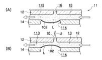
図6(A)、(B)には本発明の第2実施形態に係る液滴吐出ヘッド11のノズル近傍における構造の詳細が示されている。
<Second Embodiment>
6A and 6B show details of the structure in the vicinity of the nozzles of the
第1実施形態で開口116が設けられ大気中に開放されていた箇所は、例えば厚さ5μm程度のポリイミドやエポキシ等の樹脂からなる薄膜102で封止され、形成された液溜まり100の液Lは外気との接触を防止している。
The location where the
すなわち梁部材14には、ノズル16の吐出方向反対側に開口116が設けられて液溜まり100を形成し、液溜まり100は吐出方向反対側を薄膜102にて封止されているので、流路部材12によって形成された液流路13内を、背圧を印加された状態で液Lが給送される際には、液Lに印加された背圧で薄膜102は図6(A)に示すように膨張する。
That is, the
液溜まり100には液Lが常に供給されるため、膨張した薄膜102が封止する液溜まり100は吐出で失われる液量よりも多量に供給される液Lを一時的に保持し、余剰分の液Lは負圧を印加された吸引路113にて吸引、排出される。これにより液溜まり100は柔軟な薄膜102で表面を形成し、液滴2の慣性吐出を阻害する液Lの剪断抵抗などは抑制される。
Since the liquid L is always supplied to the
液滴2の吐出時には図6(B)に示すように薄膜102はノズル16方向(吐出方向)に変形し、液流路13内の液Lを拘束しにくい構造とされているため、液滴2の吐出に際して反吐出方向(ノズル背面)がより剛性の高い部材で密閉された構造と比較して液Lが高粘度であっても吐出を阻害しにくい構成とされる。
As shown in FIG. 6B, when the
<製造工程>
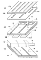
図7には、本発明の実施形態に係る液滴吐出ヘッドの製造工程の一例が示されている。先ず厚さ20μm程度のSUS板をスリット幅70μm程度で一列飛ばしにエッチング処理(スリットエッチ)し、吐出面裏側にPI(ポリイミド)フィルム14Bを融着し梁部材14とする。
<Manufacturing process>
FIG. 7 shows an example of the manufacturing process of the droplet discharge head according to the embodiment of the present invention. First, an SUS plate having a thickness of about 20 μm is subjected to etching processing (slit etching) by skipping one row with a slit width of about 70 μm, and a PI (polyimide) film 14B is fused on the back side of the discharge surface to form a
図7(A)に示すように、吐出面裏側にPI(ポリイミド)フィルム12Bを融着した厚さ10μm程度のSUS板を流路部材12Bとしてスリット幅70μmでスリットエッチ処理する。次に吐出面裏側よりYAGレーザ50などで開口116を穿孔し、液溜まり100が形成される空隙を形成する。
As shown in FIG. 7A, a SUS plate having a thickness of about 10 μm with a PI (polyimide)
次いで図7(B)に示されるように、流路部材12Bの吐出面側にPIフィルム12Cを熱融着する。YAGレーザ50などでノズル16を穿孔し、支持部材18の長手方向に並列に設けられた梁部材14を互いに分離する。また同時に流路部材12Bに設けられたスリット(=液流路13)と連通する液溜まり24がPIフィルム12Cを除去することで設けられる。このとき梁部材14、流路部材12Bは予めスリットエッチ処理が行われているので、表面のPIフィルム12Cのみレーザアブレーションで除去する。
Next, as shown in FIG. 7B, the
さらに吐出裏面からは長手方向半分までの領域に、予め信号電極32が形成されたピエゾ素子30が接合される。支持部材18内に設けられた液溜まり24に、図示しない送液ポンプより液を供給される供給ポート25が接続され、液滴吐出ヘッド10として形成される。
Furthermore, the
<第3実施形態>
図8(A)には、本発明の第3実施形態に係る液滴吐出ヘッド110のノズル16近傍の断面図が示されている。液滴吐出ヘッド110は支持部材18に一端を保持された梁部材14上に流路部材12が設けられ、流路部材12の内部には長手方向に液流路13が設けられている。
<Third Embodiment>
FIG. 8A shows a cross-sectional view of the vicinity of the
図8(A)に示すように液滴吐出ヘッド110の流路部材12は、内部長手方向に貫通した液流路13と、流路部材12に設けられたノズル16とを備え、ノズル16の裏側(反吐出方向側)には梁部材14を穿孔した開口116が設けられている。
As shown in FIG. 8A, the
梁部材14の反吐出方向(裏側)には流路部材40が設けられ、梁部材14との間には送風路44が形成されている。送風路44は図示しない送風手段と連通し、加圧された空気が矢印43のように給送される。
A
送風路44内には濾過手段としてフィルタ48が設けられ、給送される空気を濾過する。さらに送風路44内には液体を含有可能なスポンジなどの加湿手段46が設けられ、給送される空気を液Lの溶媒成分で加湿する構成とされている。
A
液流路13はノズル16を通過した後は吸引路113となり、図示しない吸引手段と連通し、負圧を印加される。矢印43のように給送された空気の一部は、液溜まり100で矢印45Aのように吸引路113へ向かい、矢印41のように余剰の液Lと共に吸引除去される。
The
また空気の他の一部は、液溜まり100より吸引路113に向かわず、矢印45Bのように図示しない空気循環路を経由して再度送風手段へと戻される。さらに空気は送風手段より送風路44へと給送され、再度矢印43のように液溜まり100に送られる。この構成とすることにより、液溜まり100を大気中に開放する構成と比較して、常にフィルタ48で濾過された空気が給送されるためゴミや異物の混入が少ない構成とされている。また、ノズル16近傍の液の乾燥を抑制することができる。
Further, the other part of the air does not go from the
<第4実施形態>
図8(B)には、本発明の第4実施形態に係る液滴吐出ヘッド111のノズル16近傍の断面図が示されている。液滴吐出ヘッド111は支持部材18に一端を保持された梁部材14上に流路部材12が設けられ、流路部材12の内部には長手方向に液流路13が設けられている。
<Fourth embodiment>
FIG. 8B shows a cross-sectional view of the vicinity of the
図8(B)に示すように液滴吐出ヘッド111の流路部材12は、内部長手方向に貫通した液流路13と、流路部材12に設けられたノズル16とを備え、ノズル16の裏側(反吐出方向側)には梁部材14を穿孔した開口116が設けられている。
As shown in FIG. 8B, the
梁部材14の反吐出方向(裏側)には流路部材40Aが設けられ、梁部材14との間には送風路44Aが形成されている。送風路44Aは図示しない送風手段と連通し、加圧された空気が矢印43Aのように給送される。
A
送風路44A内には濾過手段としてフィルタ48Aが設けられ、給送される空気を濾過する。さらに送風路44A内には液体を含有可能なスポンジなどの加湿手段46Aが設けられ、給送される空気を液Lの溶媒成分で加湿する構成とされている。
A
液流路13はノズル16を通過した後は吸引路113となり、図示しない吸引手段と連通し、負圧を印加される。矢印43Aのように給送された空気は、液溜まり100で矢印45のように吸引路113へ向かい、矢印41Aのように余剰の液Lと共に吸引除去される。
The
また梁部材14の吐出方向(表側)には流路部材40Bが設けられ、梁部材14との間には送風路44Bが形成されている。送風路44Bもまた図示しない送風手段と連通し、加圧された空気が矢印43Bのように給送される。
Further, a
さらに流路部材40Bは、ノズル16よりも送風方向下流側では流路部材12との間に吸引路42Bを形成し、給送された空気を吸引する。この吸引路42Bは図示しない負圧発生手段(吸引ポンプなど)と連通し、負圧を印加されることにより、矢印41Bのように空気およびノズル16近傍で吐出方向に溢れた液Lを吸引除去する。
Further, the
流路部材40Bには、吐出方向より見てノズル16よりも大きい開口416が設けられ、ノズル16より液滴2の吐出を阻害しない構成とされている。さらに送風路44B内にも濾過手段としてフィルタ48Bが設けられ、給送される空気を濾過する。さらに送風路44B内にも液体を含有可能なスポンジなどの加湿手段46Bが設けられ、給送される空気を液Lの溶媒成分で加湿する構成とされている。
The
この構成とすることにより、液溜まり100を大気中に開放する構成と比較して、常にフィルタ48で濾過された空気が給送されるためゴミや異物の混入が少なく、また、ノズル16近傍の液の乾燥を抑制することができる。さらに、ノズル16近傍に液Lが付着しにくい構成とされている。
By adopting this configuration, compared to the configuration in which the
<第5実施形態>
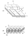
図9(A)、(B)には、本発明の第5実施形態に係る液滴吐出ヘッド112が示されている。
<Fifth Embodiment>
9A and 9B show a
本発明の第5実施形態に係る液滴吐出ヘッド112は、図9(A)に示されているように、内部に液流路13を備え長さ方向略中央にノズル16を備えた中空チューブ状の流路部材12と、流路部材12を支持する梁部材14とが柱状に接合され、両端を支持部材18が支持する構造となっている。またノズル16の反吐出方向においては梁部材14に開口116が設けられ、液溜まり100が形成されている点は各実施形態と同様である。
As shown in FIG. 9A, a
図9(A)のA−A断面を図9(B)に示す。図9(B)に示すように液滴吐出ヘッド112は梁部材14の吐出面側(表側)には中空の流路部材12が設けられ、内部に液流路13が形成されている。また反吐出面側(裏側)には流路部材40Cが設けられ、内部に吸引路42Cが形成されている。
FIG. 9B shows a cross section along A-A in FIG. As shown in FIG. 9B, in the
吸引路42Cは図示しない吸引手段と連通し、負圧を印加される。吸引路42Cはノズル16の反吐出方向に形成された液溜まり100近傍に開口し、余剰の液Lを吸引除去する。この構成とすることにより、液流路13の両端側からノズル16に向かって液Lが供給できるようになる。また、この構成において、液流路13の方端側からのみ、ノズル16に向かって液Lを供給すると、吸引路42Cを吐出面側(表側)と反吐出面側(裏側)に設けることができるようになり、上記各実施形態に比較して更に余剰の液Lの排出性に勝る構成とされている。
The suction path 42C communicates with suction means (not shown) and is applied with negative pressure. The suction path 42C opens near the
<開口位置>
図10、図11には、本発明に係る液滴吐出ヘッドの開口端からノズル中心までの距離と液面(メニスカス)との関係の一例が示されている。
<Opening position>
FIG. 10 and FIG. 11 show an example of the relationship between the distance from the opening end of the droplet discharge head according to the present invention to the center of the nozzle and the liquid level (meniscus).
ノズル16の開口サイズが50μmであった場合、開口116のサイズd1が100μm以下では図10(A)に示すようにノズル16の液膜が容易に破壊され液膜の形成が困難となる。開口116のサイズd2が150μm程度では図11(B)に示すようにノズル16の液膜が薄く、吸引路113による吸引で脈動するなど不安定となる。開口116のサイズd3が200〜400μm程度では、上記の吸引に伴う問題は発生していない。
When the opening size of the
ノズル16の開口径が25μmであった場合、吸引を行わず、液Lに背圧を印加せず毛管供給した際には、開口116のサイズが50μmであった場合のみ図11(A)に示すように吐出性に問題はなく、開口116のサイズが100〜150μm程度では図11(B)に示すように開口116へ液Lが移動して流出するなど、ノズル16における液膜形成が困難となる。また液Lへの背圧印加および吸引路113での吸引を行った場合は開口116のサイズに拘わらず液溢れ、濡れ、ノズル16間の吐出バラツキ等が発生した。
When the opening diameter of the
液Lに背圧を印加し吸引路113で吸引を行った場合、開口116のサイズ100μm以下では図11(C)に示すようにノズル16の液膜が吸引路113からの吸引で破壊され易くなり吐出バラツキが発生する。
When a back pressure is applied to the liquid L and suction is performed through the
開口116のサイズが150μm程度では図11(D)に示すようにノズル16の液膜が薄くなり、且つ液流路13からの距離が大きくなるため液膜の維持が困難となり、吐出バラツキが発生する。上記の例はすべて吐出方向より見てノズル16と開口116の図心が一致している場合の結果である。この場合、開口116の背圧側(供給側)と吸引側(下流側)の適切なサイズを両立することができない。
When the size of the
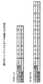
そこで開口116の背圧側(供給側)端からノズル16の中心までの距離(din)と、吸引側(下流側)端からノズル16の中心までの距離(dout)を変化させ、目視で吐出性能を判定した結果を図12に表で示す。
Accordingly, the distance (din) from the back pressure side (supply side) end of the
図12に示すように、開口116の背圧側(供給側)端からノズル16の中心までの距離がノズル16の径に対して3倍以内であれば吐出性能は良好であり、且つ吸引側(下流側)端からノズル16の中心までの距離がノズル16の径に対して3倍〜10倍の範囲にあれば吐出性能は良好となる。
As shown in FIG. 12, if the distance from the back pressure side (supply side) end of the
<その他>
尚、本発明は、上記の実施の形態に限定されるものではない。例えば、上記各実施形態ではノズル16ごとに吸引路113や送風路44を設けた構成が例示されているが、これに限定せず例えば2個あるいは4個など複数のノズル16ごとに吸引路113や送風路44を設けた構成とされていてもよい。このとき吸引路113や送風路44に対してノズル16は均等に配置されている構成であれば液膜が均一化され易い構成となる。
<Others>
In addition, this invention is not limited to said embodiment. For example, in each of the above embodiments, a configuration in which the
また、本明細書における液滴吐出ヘッドはインクジェット記録ヘッドを例にあげているが、必ずしもインクを用いた記録紙上への文字や画像の記録に限定されるものではない。すなわち、記録媒体は紙に限定されるものでなく、また吐出される液体もインクに限定されるものではない。例えば、高分子フィルムやガラス上に液を吐出してディスプレイ用カラーフィルターを作成したり、液状の半田を基板上に吐出して部品実装用のバンプを形成したりするなど、工業用的に用いられる液滴噴射装置全般に対して本発明を利用することが可能である。 In addition, although the ink jet recording head is taken as an example of the droplet discharge head in the present specification, it is not necessarily limited to recording characters and images on recording paper using ink. That is, the recording medium is not limited to paper, and the ejected liquid is not limited to ink. For example, it is used industrially, for example, to create a color filter for display by discharging liquid onto a polymer film or glass, or to form bumps for component mounting by discharging liquid solder onto a substrate. The present invention can be applied to all types of liquid droplet ejecting apparatuses.
2 液滴
10 液滴吐出ヘッド
12 流路部材
13 液流路
14 梁部材
16 ノズル
18 支持部材
20 回転エンコーダ
30 ピエゾ素子
36 アクチュエータ
40 流路部材
42 吸引路
44 送風路
46 加湿手段
48 フィルタ
100 液溜まり
113 吸引路
116 開口
124 液吸引プール
2
Claims (7)
前記ノズルに向けて液体が供給される液体流路部材と、
前記ノズルに向けて前記液体流路部材中の前記液体に背圧を印加する背圧発生手段と、
前記液体流路部材と接合もしくは液体流路部材を含み、液滴吐出面に凹となるように座屈反転変形した後、液滴吐出方向に凸となるよう座屈反転変形し、前記ノズル近傍の液体に吐出方向の慣性を与えることにより、前記ノズル近傍の液を液滴として前記ノズルより吐出させる梁部材と、
前記液体流路部材の吐出方向反対側に設けられ大気と連通した開口と、
吸引口が前記ノズルの近傍に向いた吸引路と、
前記吸引路に負圧を発生させる負圧発生手段と、
を備えた液滴吐出ヘッド。 A nozzle for discharging droplets;
A liquid flow path member to which a liquid is supplied toward the nozzle;
Back pressure generating means for applying a back pressure to the liquid in the liquid channel member toward the nozzle;
In the vicinity of the nozzle, including the liquid flow path member or including the liquid flow path member, buckling and reversing deformation so as to be concave on the droplet discharge surface, and then buckling and reversing deformation so as to be convex in the droplet discharge direction. A beam member that discharges the liquid in the vicinity of the nozzle as droplets from the nozzle by giving inertia in the discharge direction to the liquid of
An opening provided on the opposite side of the liquid flow path member in the discharge direction and communicating with the atmosphere;
A suction path whose suction port faces the vicinity of the nozzle;
Negative pressure generating means for generating a negative pressure in the suction path;
A droplet discharge head comprising:
前記送風路に正圧を発生させる送風手段と、
前記送風路に設けられ前記空気を濾過する濾過手段と、
を備えた請求項1〜請求項4の何れか1項に記載の液滴吐出ヘッド。 A blower path for sending air to the suction port of the suction path;
A blowing means for generating a positive pressure in the blowing path;
Filtering means provided in the air passage for filtering the air;
A droplet discharge head according to claim 1, comprising:
Priority Applications (2)
| Application Number | Priority Date | Filing Date | Title |
|---|---|---|---|
| JP2008322133A JP2010143048A (en) | 2008-12-18 | 2008-12-18 | Liquid droplet jetting head and liquid droplet jetting device |
| US12/469,369 US8123335B2 (en) | 2008-12-18 | 2009-05-20 | Liquid droplet ejecting head and liquid droplet ejecting apparatus |
Applications Claiming Priority (1)
| Application Number | Priority Date | Filing Date | Title |
|---|---|---|---|
| JP2008322133A JP2010143048A (en) | 2008-12-18 | 2008-12-18 | Liquid droplet jetting head and liquid droplet jetting device |
Publications (1)
| Publication Number | Publication Date |
|---|---|
| JP2010143048A true JP2010143048A (en) | 2010-07-01 |
Family
ID=42265417
Family Applications (1)
| Application Number | Title | Priority Date | Filing Date |
|---|---|---|---|
| JP2008322133A Pending JP2010143048A (en) | 2008-12-18 | 2008-12-18 | Liquid droplet jetting head and liquid droplet jetting device |
Country Status (2)
| Country | Link |
|---|---|
| US (1) | US8123335B2 (en) |
| JP (1) | JP2010143048A (en) |
Families Citing this family (9)
| Publication number | Priority date | Publication date | Assignee | Title |
|---|---|---|---|---|
| JP4466331B2 (en) * | 2004-11-05 | 2010-05-26 | 富士ゼロックス株式会社 | Inkjet recording head and inkjet recording apparatus |
| JP2010143048A (en) | 2008-12-18 | 2010-07-01 | Fuji Xerox Co Ltd | Liquid droplet jetting head and liquid droplet jetting device |
| AU2017260444B2 (en) | 2016-05-03 | 2019-05-09 | Pneuma Respiratory, Inc. | Droplet delivery device for delivery of fluids to the pulmonary system and methods of use |
| US11529476B2 (en) | 2017-05-19 | 2022-12-20 | Pneuma Respiratory, Inc. | Dry powder delivery device and methods of use |
| US11766729B2 (en) * | 2017-09-28 | 2023-09-26 | International Business Machines Corporation | Molten solder injection head with vacuum filter and differential gauge system |
| EP3691728B1 (en) | 2017-10-04 | 2024-05-22 | Pneuma Respiratory, Inc. | Electronic breath actuated in-line droplet delivery device |
| CA3079189A1 (en) | 2017-10-17 | 2019-04-25 | Pneuma Respiratory, Inc. | Nasal drug delivery apparatus and methods of use |
| CA3082192A1 (en) | 2017-11-08 | 2019-05-16 | Pneuma Respiratory, Inc. | Electronic breath actuated in-line droplet delivery device with small volume ampoule and methods of use |
| KR20240037245A (en) | 2021-06-22 | 2024-03-21 | 뉴마 레스퍼러토리 인코포레이티드 | Droplet delivery device by push ejection |
Citations (6)
| Publication number | Priority date | Publication date | Assignee | Title |
|---|---|---|---|---|
| JPH08149253A (en) * | 1994-09-22 | 1996-06-07 | Toshiba Corp | Ink jet recording device |
| JP2002533247A (en) * | 1998-12-24 | 2002-10-08 | ザール テクノロジー リミテッド | Droplet deposition device |
| JP2003165230A (en) * | 2001-11-30 | 2003-06-10 | Hitachi Printing Solutions Ltd | Ink-jet recording head and its recorder |
| JP2007160735A (en) * | 2005-12-14 | 2007-06-28 | Fuji Xerox Co Ltd | Liquid droplet ejection head |
| JP2008030357A (en) * | 2006-07-31 | 2008-02-14 | Fuji Xerox Co Ltd | Liquid droplet discharge head |
| JP2008207336A (en) * | 2007-02-23 | 2008-09-11 | Fuji Xerox Co Ltd | Droplet discharg head |
Family Cites Families (21)
| Publication number | Priority date | Publication date | Assignee | Title |
|---|---|---|---|---|
| US4336544A (en) * | 1980-08-18 | 1982-06-22 | Hewlett-Packard Company | Method and apparatus for drop-on-demand ink jet printing |
| EP0703081A3 (en) * | 1994-09-22 | 1997-03-12 | Toshiba Kk | Ink jet printing apparatus with controlled compression and ejection of colorants in liquid ink |
| JP3372758B2 (en) | 1996-06-07 | 2003-02-04 | キヤノン株式会社 | Liquid discharge method, liquid discharge head, liquid discharge device, liquid container, and head cartridge |
| JP3408059B2 (en) * | 1995-09-22 | 2003-05-19 | キヤノン株式会社 | Liquid ejection head, liquid ejection device, and recovery method for liquid ejection device |
| CN1087228C (en) * | 1995-09-22 | 2002-07-10 | 佳能株式会社 | Liquid discharging method, liquid discharging head, liquid discharging apparatus, liquid container and head cartridge |
| JPH0985946A (en) * | 1995-09-25 | 1997-03-31 | Sharp Corp | Ink jet head and manufacture thereof |
| KR0185329B1 (en) * | 1996-03-27 | 1999-05-15 | 이형도 | Recording method using motor inertia of recording liquid |
| JPH10307381A (en) * | 1997-03-04 | 1998-11-17 | Fuji Photo Film Co Ltd | Liquid injector and production of liquid injector |
| JP2001205814A (en) | 2000-01-28 | 2001-07-31 | Kyocera Corp | Ink-jet head |
| JP2002234175A (en) | 2001-02-08 | 2002-08-20 | Canon Inc | Method and apparatus for preventing ink viscosity increase in liquid jet apparatus, and apparatus for manufacturing color filter |
| JP2003118114A (en) | 2001-10-15 | 2003-04-23 | Sharp Corp | Ink jet head and its manufacturing method |
| JP2003220702A (en) | 2002-01-31 | 2003-08-05 | Konica Corp | Inkjet printer |
| US6644786B1 (en) * | 2002-07-08 | 2003-11-11 | Eastman Kodak Company | Method of manufacturing a thermally actuated liquid control device |
| US6755509B2 (en) * | 2002-11-23 | 2004-06-29 | Silverbrook Research Pty Ltd | Thermal ink jet printhead with suspended beam heater |
| JP4466333B2 (en) | 2004-11-05 | 2010-05-26 | 富士ゼロックス株式会社 | Inkjet recording head and inkjet recording apparatus |
| JP4466332B2 (en) | 2004-11-05 | 2010-05-26 | 富士ゼロックス株式会社 | Inkjet recording head and inkjet recording apparatus |
| JP4539295B2 (en) | 2004-11-05 | 2010-09-08 | 富士ゼロックス株式会社 | Inkjet recording head and inkjet recording apparatus |
| JP4466331B2 (en) | 2004-11-05 | 2010-05-26 | 富士ゼロックス株式会社 | Inkjet recording head and inkjet recording apparatus |
| JP3925547B2 (en) | 2005-09-07 | 2007-06-06 | ブラザー工業株式会社 | Inkjet printer |
| JP4636165B2 (en) * | 2008-10-27 | 2011-02-23 | 富士ゼロックス株式会社 | Droplet discharge apparatus and image forming apparatus |
| JP2010143048A (en) | 2008-12-18 | 2010-07-01 | Fuji Xerox Co Ltd | Liquid droplet jetting head and liquid droplet jetting device |
-
2008
- 2008-12-18 JP JP2008322133A patent/JP2010143048A/en active Pending
-
2009
- 2009-05-20 US US12/469,369 patent/US8123335B2/en not_active Expired - Fee Related
Patent Citations (6)
| Publication number | Priority date | Publication date | Assignee | Title |
|---|---|---|---|---|
| JPH08149253A (en) * | 1994-09-22 | 1996-06-07 | Toshiba Corp | Ink jet recording device |
| JP2002533247A (en) * | 1998-12-24 | 2002-10-08 | ザール テクノロジー リミテッド | Droplet deposition device |
| JP2003165230A (en) * | 2001-11-30 | 2003-06-10 | Hitachi Printing Solutions Ltd | Ink-jet recording head and its recorder |
| JP2007160735A (en) * | 2005-12-14 | 2007-06-28 | Fuji Xerox Co Ltd | Liquid droplet ejection head |
| JP2008030357A (en) * | 2006-07-31 | 2008-02-14 | Fuji Xerox Co Ltd | Liquid droplet discharge head |
| JP2008207336A (en) * | 2007-02-23 | 2008-09-11 | Fuji Xerox Co Ltd | Droplet discharg head |
Also Published As
| Publication number | Publication date |
|---|---|
| US8123335B2 (en) | 2012-02-28 |
| US20100156995A1 (en) | 2010-06-24 |
Similar Documents
| Publication | Publication Date | Title |
|---|---|---|
| JP2010143048A (en) | Liquid droplet jetting head and liquid droplet jetting device | |
| US10265961B2 (en) | Wiping member, liquid ejecting apparatus, wiping method in cleaning mechanism, and method of controlling liquid ejecting apparatus | |
| JP5846237B2 (en) | Liquid ejector | |
| JP5107891B2 (en) | Droplet ejection device | |
| JP5030423B2 (en) | Inkjet head and inkjet recording apparatus | |
| JP2008030357A (en) | Liquid droplet discharge head | |
| JP7107097B2 (en) | Droplet ejection device and maintenance method for droplet ejection device | |
| JP4553129B2 (en) | Liquid ejecting head and liquid ejecting apparatus | |
| JP2009090534A (en) | Droplet ejection device | |
| JP4900177B2 (en) | Droplet ejector | |
| JP2019014158A (en) | Droplet discharge device and maintenance method of the same | |
| JP4643294B2 (en) | Head maintenance device | |
| JP4035503B2 (en) | Inkjet recording head | |
| JP2012126081A (en) | Nozzle plate, droplet ejecting device, image forming apparatus, and method for manufacturing the nozzle plate | |
| JP4765601B2 (en) | Droplet discharge head | |
| JP2012250484A (en) | Liquid droplet ejection head, and image forming apparatus | |
| JP2004160827A (en) | Liquid droplet jetting head, its manufacturing method, ink cartridge, and inkjet recording device | |
| JP2011178133A (en) | Liquid injection head, liquid injection head unit and liquid injection device | |
| JP4636165B2 (en) | Droplet discharge apparatus and image forming apparatus | |
| JP6108108B2 (en) | Liquid ejecting head and liquid ejecting apparatus | |
| JP4307938B2 (en) | Electrostatic actuator, droplet discharge head, liquid cartridge, and image forming apparatus | |
| JP2010143049A (en) | Liquid jetting head and liquid jetting device | |
| JP2003094641A (en) | Droplet discharge head and manufacturing method therefor | |
| JP6094777B2 (en) | Channel member, liquid ejecting head, and liquid ejecting apparatus | |
| JP2017189969A (en) | Nozzle plate, liquid ejection head, liquid ejection unit, device for ejecting liquid, and manufacturing method for nozzle plate |
Legal Events
| Date | Code | Title | Description |
|---|---|---|---|
| A977 | Report on retrieval |
Free format text: JAPANESE INTERMEDIATE CODE: A971007 Effective date: 20100907 |
|
| A131 | Notification of reasons for refusal |
Free format text: JAPANESE INTERMEDIATE CODE: A131 Effective date: 20100914 |
|
| A521 | Request for written amendment filed |
Free format text: JAPANESE INTERMEDIATE CODE: A523 Effective date: 20101112 |
|
| A02 | Decision of refusal |
Free format text: JAPANESE INTERMEDIATE CODE: A02 Effective date: 20101221 |