JP2010142478A - X-ray ct apparatus - Google Patents
X-ray ct apparatus Download PDFInfo
- Publication number
- JP2010142478A JP2010142478A JP2008324199A JP2008324199A JP2010142478A JP 2010142478 A JP2010142478 A JP 2010142478A JP 2008324199 A JP2008324199 A JP 2008324199A JP 2008324199 A JP2008324199 A JP 2008324199A JP 2010142478 A JP2010142478 A JP 2010142478A
- Authority
- JP
- Japan
- Prior art keywords
- data
- ray
- tube voltage
- projection
- image
- Prior art date
- Legal status (The legal status is an assumption and is not a legal conclusion. Google has not performed a legal analysis and makes no representation as to the accuracy of the status listed.)
- Granted
Links
- 238000001514 detection method Methods 0.000 claims abstract description 18
- 230000005540 biological transmission Effects 0.000 claims abstract description 15
- 230000009977 dual effect Effects 0.000 abstract description 28
- 238000003384 imaging method Methods 0.000 abstract description 23
- 238000000034 method Methods 0.000 description 23
- 238000002591 computed tomography Methods 0.000 description 21
- 238000004364 calculation method Methods 0.000 description 10
- 238000006243 chemical reaction Methods 0.000 description 7
- 238000013480 data collection Methods 0.000 description 4
- 238000010586 diagram Methods 0.000 description 3
- 238000007781 pre-processing Methods 0.000 description 3
- 230000007423 decrease Effects 0.000 description 1
- 230000000593 degrading effect Effects 0.000 description 1
- 230000006870 function Effects 0.000 description 1
- 238000010606 normalization Methods 0.000 description 1
- 239000000126 substance Substances 0.000 description 1
Images


Landscapes
- Apparatus For Radiation Diagnosis (AREA)
Abstract
Description
本発明は、X線CT(Computed Tomography)装置に関し、特にデュアルエネルギー(dual energy)撮影に関する。 The present invention relates to an X-ray CT (Computed Tomography) apparatus, and more particularly to dual energy imaging.
X線CT装置を用いたデュアルエネルギー撮影方法が知られている。その1つとして、X線管の管電圧を高い管電圧と低い管電圧とに数ビュー(view)単位で繰り返し切り換えながら被検体にX線を照射して、複数ビューにて被検体の透過X線を検出器で検出し、透過X線の検出信号強度に基づく上記複数ビューのプロジェクション(projection)を用いていわゆるデュアルエネルギー画像を生成する方法がある(例えば、特許文献1,図4等参照)。
ところで、デュアルエネルギー撮影では、生成画像の画質をよくするため、透過X線の検出信号強度におけるフォトンノイズを、高い管電圧のときと低い管電圧のときとで所定レベル以下にし、更には同レベルにすることが望ましい。そのため、管電圧が変わっても被検体に照射されるX線の線量が一定となるよう、高い管電圧のときよりも低い管電圧のときに管電流をより大きく設定するのが理想である。 By the way, in the dual energy imaging, in order to improve the image quality of the generated image, the photon noise in the detected signal intensity of the transmitted X-ray is set to a predetermined level or less at a high tube voltage and a low tube voltage, and further to the same level. It is desirable to make it. Therefore, it is ideal to set the tube current larger when the tube voltage is lower than when the tube voltage is high, so that the dose of X-rays irradiated to the subject is constant even when the tube voltage changes.
一方、X線管の管電流は管電圧と違って高速での切換えが難しく、単一のX線管を用いる場合には、高い管電圧と低い管電圧とで管電流を大きく変えることができない場合がある。また、この場合に、仮に管電流を低い管電圧に合わせて設定すると、高い管電圧のときに被検体に照射するX線の線量が過多になり、被検体への被曝が増大するという問題がある。 On the other hand, the tube current of the X-ray tube is difficult to switch at high speed unlike the tube voltage, and when a single X-ray tube is used, the tube current cannot be changed greatly between a high tube voltage and a low tube voltage. There is a case. In this case, if the tube current is set in accordance with a low tube voltage, the X-ray dose applied to the subject becomes excessive when the tube voltage is high, and the exposure to the subject increases. is there.
そのため、デュアルエネルギー撮影において、上記のように管電流を大きく変えることができない事情がある場合には、低い管電圧のときに理想よりも低くなる電流値を設定することになり、低い管電圧側で被検体に照射するX線の線量が不足し、生成画像にアーチファクト(artifact)が発生する場合がある。 Therefore, in dual energy imaging, when there is a situation where the tube current cannot be changed greatly as described above, a current value lower than ideal is set at a low tube voltage, and the low tube voltage side is set. In some cases, the X-ray dose irradiated to the subject is insufficient, and artifacts may occur in the generated image.
なお、線量不足による生成画像のアーチファクトを抑えるためのプロジェクション補正方法が種々提案されているが(例えば特許文献、特開2001−112749号公報,特開2004−208713号公報等参照)、これらの補正方法は単一の管電圧による撮影を対象としており、デュアルエネルギー撮影にそのまま適用しても生成画像を精度よく高画質に得ることは難しい。 Various projection correction methods for suppressing artifacts in the generated image due to insufficient dose have been proposed (see, for example, Patent Documents, Japanese Patent Application Laid-Open Nos. 2001-12749, 2004-208713, etc.). The method is intended for imaging with a single tube voltage, and it is difficult to obtain a generated image with high accuracy with high accuracy even if applied directly to dual energy imaging.
本発明は、上記事情に鑑み、高い管電圧と低い管電圧とで管電流の差が小さいデュアルエネルギー撮影においても画像を精度よく高画質に得ることができるX線CT装置を提供することを目的とする。 SUMMARY OF THE INVENTION In view of the above circumstances, an object of the present invention is to provide an X-ray CT apparatus capable of obtaining an image with high accuracy and high image quality even in dual energy imaging in which a difference in tube current is small between a high tube voltage and a low tube voltage. And
第1の観点では、本発明は、第1の管電圧と前記第1の管電圧より小さい第2の管電圧とにより被検体にX線を照射するX線管と、前記被検体の透過X線を検出するX線検出器と、前記X線検出器による透過X線の検出信号強度に基づく複数ビューの投影データ(data)を用いて画像を生成する画像生成手段とを備えるX線CT装置であって、前記画像生成手段が、前記第2の管電圧による投影データPLを構成するデータの中で、基になった透過X線の検出信号強度が所定レベル(level)以下であるデータを特定する特定手段と、前記第1の管電圧による投影データPHを構成しており、前記特定されたデータの基になった透過X線と同一のパスおよび/または該パスに近接するパスを通る透過X線によるデータに基づいて、前記特定されたデータを補正する補正手段と、前記投影データPHと前記補正されたデータを含む投影データPLとを用いて画像を作成する作成手段とを備えるX線CT装置を提供する。 In a first aspect, the present invention relates to an X-ray tube that irradiates a subject with X-rays using a first tube voltage and a second tube voltage that is smaller than the first tube voltage, and transmission X of the subject. X-ray CT apparatus comprising: an X-ray detector for detecting a line; and an image generating means for generating an image using projection data (data) of a plurality of views based on a detected signal intensity of transmitted X-rays by the X-ray detector And the image generation means outputs data in which the detected signal intensity of the base transmission X-ray is equal to or lower than a predetermined level among the data constituting the projection data PL by the second tube voltage. The specifying means for specifying and the projection data PH based on the first tube voltage constitute the same path as the transmitted X-ray that is the basis of the specified data and / or the path close to the path. Based on data from transmitted X-rays, the identified To provide an X-ray CT apparatus and a creating means for creating an image by using a correction means for correcting the over data, the projection data PL including the is the projection data PH correction data.
ここで、「1または数ビュー」は、1〜10ビュー程度である。 Here, “1 or several views” is about 1 to 10 views.
「ビュー」は、X線管のビュー角度位置と、X線管がそのビュー角度位置に位置するときの時刻とにより規定される概念である。 “View” is a concept defined by the view angle position of the X-ray tube and the time when the X-ray tube is positioned at the view angle position.
「X線検出器」は、X線管から発生するX線ビーム(beam)の扇状に広がる方向に並ぶ複数のX線検出素子により構成される検出器列を1または複数有する。 The “X-ray detector” has one or a plurality of detector rows each composed of a plurality of X-ray detection elements arranged in a fan-shaped direction of an X-ray beam generated from an X-ray tube.
「検出信号強度」は、AD(analog-digital)変換後ではカウント(count)数(値)ともいう。 The “detection signal intensity” is also called a count number (value) after AD (analog-digital) conversion.
「投影データ」は、例えば、いわゆるプロジェクション(データ)である。プロジェクションは、X線検出器の各X線検出素子における透過X線の検出信号強度を対数変換して得られる各チャネル(channel)のデータで構成されており、各チャネルのデータは、そのデータの基になった透過X線の検出信号強度が小さいほど大きい値を取る。 “Projection data” is, for example, so-called projection (data). The projection is composed of data of each channel (log) obtained by logarithmically converting the detected signal intensity of the transmitted X-ray in each X-ray detection element of the X-ray detector, and the data of each channel is the data of the data. The smaller the detection signal intensity of the base transmission X-ray, the larger the value.
第2の観点では、本発明は、前記X線管が、管電圧を前記第1の管電圧と前記第2の管電圧とに1または数ビュー単位にて繰り返し切り換えながら前記被検体にX線を照射する上記第1の観点のX線CT装置を提供する。 In a second aspect, the present invention provides the X-ray tube to the subject while repeatedly switching the tube voltage between the first tube voltage and the second tube voltage in units of one or several views. An X-ray CT apparatus according to the first aspect is provided.
第3の観点では、本発明は、前記補正手段が、ビューが前記特定されたデータと近接しており、チャネルが前記特定されたデータと同一である対応データおよび/または該対応データに近接するデータに基づいて前記特定されたデータを補正する上記第2の観点のX線CT装置を提供する。 In a third aspect, the present invention provides the correction means, wherein a view is close to the identified data, and a channel is close to the corresponding data and / or the corresponding data that is the same as the specified data. An X-ray CT apparatus according to the second aspect of the present invention that corrects the specified data based on data is provided.
第4の観点では、本発明は、前記第1の管電圧による投影データPHおよび前記第2の管電圧による投影データPLが、前記第1の管電圧による投影データと前記第2の管電圧による投影データの少なくとも一方に対してビュー方向における補間処理を行うことにより、同一の複数ビューについてそれぞれ得られる投影データであり、前記補正手段が、ビューおよびチャネルが前記特定されたデータと同一である対応データおよび/または該対応データに近接するデータに基づいて、前記特定されたデータを補正する上記第2の観点のX線CT装置を提供する。 In a fourth aspect, according to the present invention, the projection data PH based on the first tube voltage and the projection data PL based on the second tube voltage are based on the projection data based on the first tube voltage and the second tube voltage. Projection data obtained for each of the same plurality of views by performing interpolation processing in at least one of the projection data in the view direction, and the correction unit has the same view and channel as the identified data The X-ray CT apparatus according to the second aspect of the present invention corrects the specified data based on data and / or data close to the corresponding data.
第5の観点では、本発明は、前記補正手段が、前記対応データに近接する所定数のデータの代表値と前記特定されたデータに近接する所定数のデータの代表値との比に基づいて前記特定されたデータを補正する上記第3の観点または第4の観点のX線CT装置を提供する。 In a fifth aspect, the present invention is based on a ratio between the representative value of a predetermined number of data close to the corresponding data and the representative value of a predetermined number of data close to the specified data. The X-ray CT apparatus according to the third aspect or the fourth aspect, which corrects the identified data.
第6の観点では、本発明は、前記代表値が、平均値、中間値、最大値、および最小値のいずれかである上記第5の観点のX線CT装置を提供する。 In a sixth aspect, the present invention provides the X-ray CT apparatus according to the fifth aspect, wherein the representative value is any one of an average value, an intermediate value, a maximum value, and a minimum value.
第7の観点では、本発明は、前記補正手段が、前記特定されたデータを、前記比に基づく係数を前記対応データに乗算してなるデータに置換する上記第5の観点または第6の観点のX線CT装置を提供する。 In a seventh aspect, the present invention provides the fifth or sixth aspect, wherein the correction means replaces the specified data with data obtained by multiplying the corresponding data by a coefficient based on the ratio. An X-ray CT apparatus is provided.
第8の観点では、本発明は、前記補正手段が、前記特定されたデータを、前記比に基づく係数を前記対応データに近接するデータに乗算してなるデータに置換する上記第5の観点または第6の観点のX線CT装置を提供する。 In an eighth aspect, the present invention provides the fifth aspect, wherein the correction unit replaces the identified data with data obtained by multiplying the data based on the ratio by data close to the corresponding data. An X-ray CT apparatus according to a sixth aspect is provided.
第9の観点では、本発明は、前記所定レベルが、前記投影データPLまたは該投影データPLを構成するデータの基になる透過X線の検出信号強度に基づいて変化する上記第1の観点から第8の観点のいずれか1つの観点のX線CT装置を提供する。 In a ninth aspect, the present invention provides the first aspect, wherein the predetermined level changes based on the detected data intensity of the transmission X-ray that is the basis of the projection data PL or data constituting the projection data PL. An X-ray CT apparatus according to any one of the eighth aspects is provided.
第10の観点では、本発明は、前記作成手段が、前記投影データPHに基づく画像と前記補正されたデータを含む投影データPLに基づく画像との比または差分を表す画像を作成する第1の観点から第9の観点のいずれか1つの観点のX線CT装置を提供する。 In a tenth aspect, the present invention provides the first in which the creation unit creates an image representing a ratio or difference between an image based on the projection data PH and an image based on the projection data PL including the corrected data. An X-ray CT apparatus according to any one of the ninth aspects from a viewpoint is provided.
「比または差分を表す画像」は、対応する画素間における画素値の比または差分をその画素と同じ位置の画素の画素値として作成される画像である。なお、比または差分を取る前に対象となる2画像の少なくとも一方の画素値をシフト(shift)変換またはリニア(linear)変換する場合を含む。 An “image representing a ratio or difference” is an image created by using a pixel value ratio or difference between corresponding pixels as a pixel value of a pixel at the same position as that pixel. It includes a case where at least one pixel value of two target images is subjected to shift conversion or linear conversion before taking the ratio or difference.
第11の観点では、本発明は、前記作成手段が、前記投影データPHに基づいて第1の画像を再構成するとともに、前記補正されたデータを含む投影データPLに基づいて第2の画像を再構成し、前記第1および第2の画像を用いて前記比または差分を表す画像を作成する上記第10の観点のX線CT装置を提供する。 In an eleventh aspect, according to the present invention, the creation unit reconstructs the first image based on the projection data PH, and generates the second image based on the projection data PL including the corrected data. The X-ray CT apparatus according to the tenth aspect is provided that reconstructs and creates an image representing the ratio or difference using the first and second images.
第12の観点では、本発明は、前記作成手段が、前記投影データPHと前記補正されたデータを含む投影データPLとを用いて所定の投影データを作成し、該所定の投影データに基づいて前記比または差分を表わす画像を再構成する上記第10の観点のX線CT装置を提供する。 In a twelfth aspect, according to the present invention, the creating means creates predetermined projection data using the projection data PH and the projection data PL including the corrected data, and based on the predetermined projection data The X-ray CT apparatus according to the tenth aspect for reconstructing an image representing the ratio or difference is provided.
本発明によれば、上記構成により、低い管電圧による投影データにおける、基になった透過X線の検出信号強度が小さい補正対象データを、高い管電圧による投影データにおける、補正対象データの対応データやその近接データを基に補正するので、透過X線の検出信号強度が大きいことから信頼性が高く、基になった透過X線のパスが補正対象データと略同じであることから本来得られるべきデータと強い相関関係を有するデータを用いて補正対象データを補正することができ、高い管電圧と低い管電圧とで管電流の差が小さいデュアルエネルギー撮影においても画像を精度よく高画質に得ることができる。 According to the present invention, according to the above configuration, the correction target data having a low detection signal intensity of the base transmission X-ray in the projection data with a low tube voltage is converted into the corresponding data of the correction target data in the projection data with a high tube voltage. And correction based on the proximity data thereof, the detection signal intensity of the transmitted X-rays is high, so that the reliability is high, and the original transmission X-ray path is substantially the same as the correction target data. Data to be corrected can be corrected using data that has a strong correlation with power data, and high-quality images can be obtained with high image quality even in dual energy imaging where the difference in tube current is small between high and low tube voltages. be able to.
以下、図に示す実施の形態により本発明をさらに詳細に説明する。なお、これにより本発明が限定されるものではない。 Hereinafter, the present invention will be described in more detail with reference to embodiments shown in the drawings. Note that the present invention is not limited thereby.
図1は、本実施形態にかかるX線CT装置100を示す構成図である。
FIG. 1 is a configuration diagram showing an
このX線CT装置100は、操作コンソール(console)1と、寝台装置10と、走査ガントリ(gantry)20とを具備している。
The X-ray
操作コンソール1は、ユーザ(user)の入力を受け付ける入力装置2と、デュアルエネルギー撮影を行うための各種の制御や画像を生成するための各種のデータ処理等を行う中央処理装置3と、走査ガントリ20で取得したデータを収集するデータ収集バッファ(buffer)5と、画像を表示するモニタ(monitor)6と、プログラム(program)やデータ等を記憶する記憶装置7とを具備している。
The operation console 1 includes an
寝台装置10は、撮像対象Hを載せて走査ガントリ20の開口部Bに入れ出しするテーブル(table)12を具備している。テーブル12は、寝台装置10に内蔵するモータ(motor)で昇降および水平直線移動される。なお、ここでは、テーブル12の直線移動方向をz方向、鉛直方向をy方向、z方向およびy方向に垂直な水平方向をx方向とする。
The
走査ガントリ20は、回転部15と回転部15を回転可能に支持する本体部20aとを有する。回転部15には、X線管21と、X線管21を制御するX線コントローラ(controller)22と、X線管21から発生したコーンビーム(cone beam)X線を整形するコリメータ(collimator)23と、X線検出素子がチャネル方向に複数配置された検出器列をz方向に複数配列してなるX線検出器24と、X線検出器24の出力を投影データに変換して収集するDAS(Data Acquisition System)25と、X線コントローラ22,コリメータ23,DAS25の制御を行う回転部コントローラ26とが搭載される。本体部20aは、制御信号などを操作コンソール1や寝台装置10とやり取りする制御コントローラ29を具備する。回転部15と本体部20aとは、スリップリング(slip ring)30を介して電気的に接続されている。
The
なお、走査ガントリは、本発明におけるX線照射・検出手段の実施形態の一例である。また、中央処理装置3は、本発明における特定手段、補正手段および作成手段を有する画像生成手段の実施形態の一例であり、これらの手段は中央処理装置3の機能により実現される。 The scanning gantry is an example of an embodiment of the X-ray irradiation / detection means in the present invention. The central processing unit 3 is an example of an embodiment of an image generation unit having a specifying unit, a correction unit, and a creation unit in the present invention, and these units are realized by the functions of the central processing unit 3.
これより、本実施形態におけるデュアルエネルギー撮影による画像生成処理について説明する。 Hereafter, the image generation process by dual energy imaging in this embodiment will be described.
図2は、本実施形態におけるデュアルエネルギー撮影による画像生成処理の一例を示すフロー(flow)図である。 FIG. 2 is a flow diagram showing an example of image generation processing by dual energy imaging in the present embodiment.
ステップ(step)S1では、スキャン(scan)計画を立てる。ここで、ユーザが入力装置2を介して入力した情報を基に、デュアルエネルギー撮影に必要な諸種のスキャン条件を設定する。スキャン条件としては、例えば、スライス(slice)厚、スキャン範囲、切換え管電圧、管電流、回転部15の1回転時間(回転速度)、テーブルスピード等がある。なお、切換え管電圧は、例えば、高い管電圧(第1の管電圧)HVを140kV、低い管電圧(第2の管電圧)LVを80kVに設定する。1回転時間は、例えば1秒に設定する。また、管電流は、例えば120mAに設定する。
In step S1, a scan plan is created. Here, various scanning conditions necessary for dual energy imaging are set based on information input by the user via the
ステップS2では、設定されたスキャン条件に従ってスキャンを実行することによりデュアルエネルギー撮影を行う。まず、回転部15を回転させる。次に、例えば図3に示すように、管電圧を高い管電圧HVと低い管電圧LVとに1ビュー単位で交互に切り換えながら、X線管21の焦点FからのX線Xbを被検体Hが置かれる撮像視野SFOVに照射する。X線検出器24は、各チャネルにおける被検体Hの透過X線の検出信号を出力する。DAS25は、その各チャネルの検出信号をビュー単位で収集してAD変換し、検出信号強度に応じたカウント値を有するローデータ(raw data)をデータ収集バッファ5に送る。データ収集バッファ5は、そのローデータを記憶装置7に記憶する。なお、スキャンするビュー数は、例えば2000ビュー程度とする。すなわち、高い管電圧HVにより1000ビュー程度、低い管電圧LVにより1000ビュー程度、データを収集する。
In step S2, dual energy imaging is performed by executing scanning according to the set scanning conditions. First, the rotating unit 15 is rotated. Next, for example, as shown in FIG. 3, the X-ray Xb from the focal point F of the
ステップS3では、管電圧毎に前処理を行う。まず、中央処理装置3が、指定された所定のスライス位置に対応する所定ビュー角度分のローデータを記憶装置7から読み出す。そして、読み出したローデータを高い管電圧HVによるローデータと低い管電圧LVによるローデータとに分け、それぞれに所定の前処理を行う。前処理としては、例えば、対数変換、ビームハードニング(beam hardening)補正、リファレンスチャネル(reference
channel)を用いたローデータの正規化(リファレンス補正)等がある。なお、ここでは、ローデータのカウント値を対数変換して得られるデータをプロジェクション(投影データ)と呼ぶ。また、高い管電圧HVによるローデータを対数変換して得られるデータを高い管電圧HVによるプロジェクション、低い管電圧LVによるローデータを対数変換して得られるデータを低い管電圧LVによるプロジェクションと呼ぶことにする。
In step S3, preprocessing is performed for each tube voltage. First, the central processing unit 3 reads out raw data for a predetermined view angle corresponding to a specified predetermined slice position from the
normalization (reference correction) of raw data using (channel). Here, data obtained by logarithmically converting the count value of raw data is referred to as projection (projection data). Further, data obtained by logarithmic conversion of low data with a high tube voltage HV is referred to as projection by a high tube voltage HV, and data obtained by logarithm conversion of low data with a low tube voltage LV is referred to as projection by a low tube voltage LV. To.
ステップS4では、低い管電圧によるプロジェクションの補正を行う。この補正の内容については、後ほど詳しく説明する。 In step S4, the projection is corrected with a low tube voltage. The details of this correction will be described in detail later.
ステップS5では、管電圧毎に画像再構成処理を行う。すなわち、高い管電圧HVによる所定ビュー角度分のプロジェクションを画像再構成処理して高い管電圧HVによる断層像GHを得る。また、低い管電圧LVによる所定ビュー角度分のプロジェクションを画像再構成処理して低い管電圧LVによる断層像GLを得る。画像再構成処理には、例えばフィルタード・バックプロジェクション(filtered backprojection)を用いる。 In step S5, image reconstruction processing is performed for each tube voltage. That is, a projection corresponding to a predetermined view angle with a high tube voltage HV is subjected to image reconstruction processing to obtain a tomographic image GH with a high tube voltage HV. In addition, a projection corresponding to a predetermined view angle with a low tube voltage LV is subjected to image reconstruction processing to obtain a tomographic image GL with a low tube voltage LV. For the image reconstruction process, for example, filtered backprojection is used.
ステップS6では、高い管電圧HVによる断層像GHと低い管電圧LVによる断層像GLとを用いてデュアルエネルギー画像DGを作成する。デュアルエネルギー画像DGとしては、例えば、断層像GHと断層像GLとの比を表す比画像、断層像GHと断層像GLとの差分を表す差分画像等がある。いずれも断層像中の物質を特定するのに有効な画像として知られている。なお、デュアルエネルギー画像は、高い管電圧によるプロジェクションと低い管電圧によるプロジェクションとを用いて所定のプロジェクションを作成し、その所定のプロジェクションを画像再構成処理しても同様に得られる。よって、デュアルエネルギー画像の作成手順は、本実施形態に限定されない。 In step S6, a dual energy image DG is created using a tomographic image GH with a high tube voltage HV and a tomographic image GL with a low tube voltage LV. Examples of the dual energy image DG include a ratio image representing a ratio between the tomographic image GH and the tomographic image GL, a difference image representing a difference between the tomographic image GH and the tomographic image GL, and the like. Both are known as effective images for identifying a substance in a tomographic image. Note that a dual energy image can be obtained in the same manner by creating a predetermined projection using a projection using a high tube voltage and a projection using a low tube voltage, and performing image reconstruction processing on the predetermined projection. Therefore, the creation procedure of the dual energy image is not limited to this embodiment.
ステップS7では、作成したデュアルエネルギー画像DGをモニタ6に表示する。
In step S7, the created dual energy image DG is displayed on the
ここで、ステップS4における低い管電圧によるプロジェクションの補正の内容について詳しく説明する。なお、ここでは、簡単化のため、単一の検出器列により収集されたデータに注目して説明する。また、ビュー番号をv、チャネル番号をiで表し、低い管電圧LVによるローデータのカウント値をCL(i,v)、高い管電圧HVによるプロジェクションのデータをPH(i,v)、低い管電圧LVによるプロジェクションのデータをPL(i,v)でそれぞれ表す。 Here, the details of the correction of the projection due to the low tube voltage in step S4 will be described in detail. Here, for the sake of simplicity, description will be given focusing on data collected by a single detector array. Further, the view number is represented by v, the channel number is represented by i, the count value of the low data by the low tube voltage LV is CL (i, v), the projection data by the high tube voltage HV is PH (i, v), and the low tube Projection data based on the voltage LV is represented by PL (i, v).
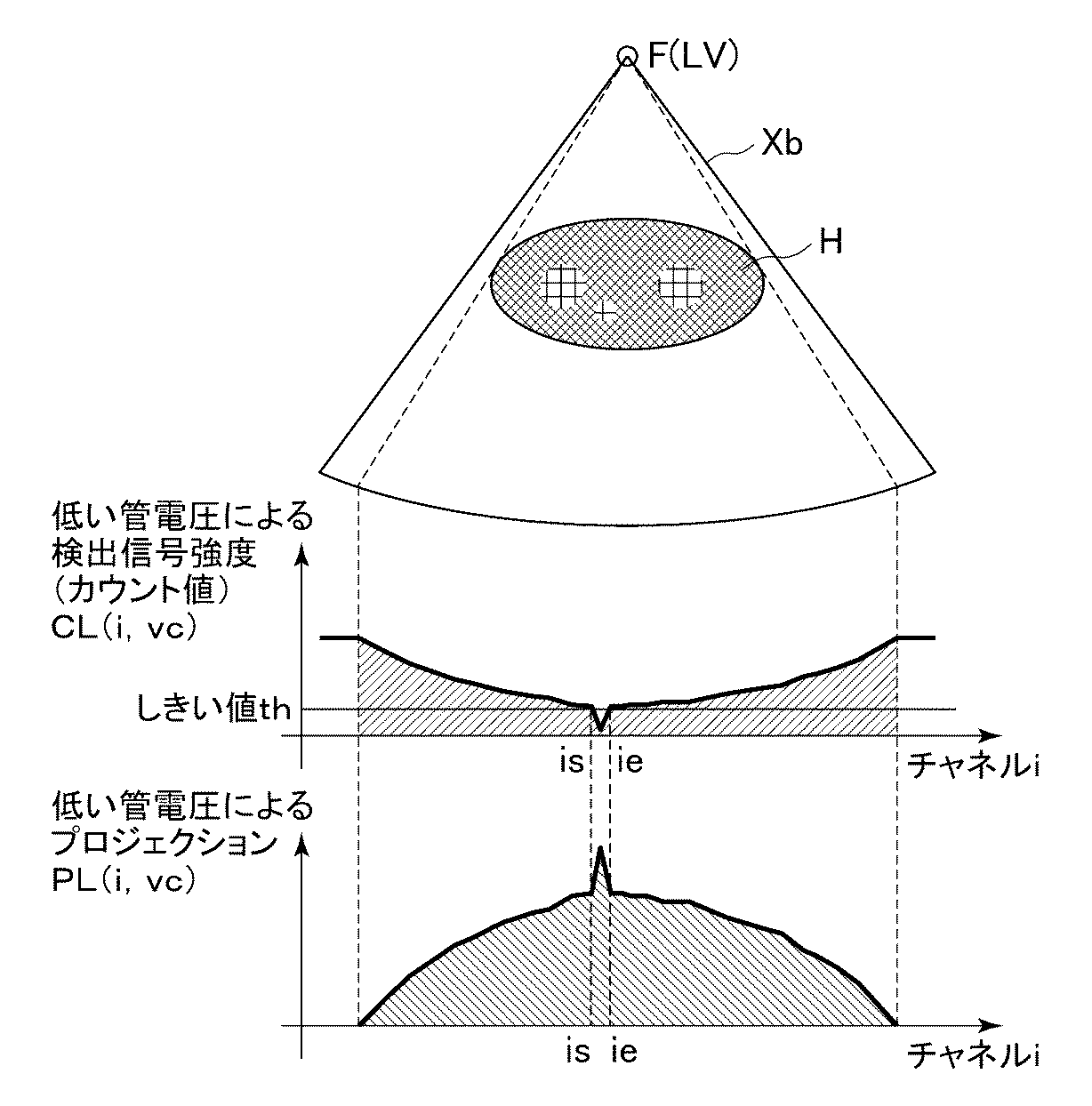
図4は、管電圧が低い管電圧LVであるビュー番号vcのビューのときに、X線XbをX線管21の焦点Fから被検体Hに照射したときに得られるローデータのカウント値CL(i,vc)とプロジェクションPL(i,vc)を示す図である。
FIG. 4 shows a count value CL of raw data obtained when the subject H is irradiated with the X-ray Xb from the focal point F of the
管電圧をビュー単位で高速に切り換えるデュアルエネルギー撮影の場合、前述したように、低い管電圧LVのときに発生するX線Xbの線量が少なくなるため、低い管電圧LVによるローデータのカウント値CL(i,vc)は、高い管電圧HVの場合よりも全体的に小さくなる。ローデータの中でカウント値が非常に小さいチャネルのデータはフォトンノイズあるいはショットノイズ(shot noise)と呼ばれるノイズの影響を大きく受けるため、信頼性が低く、再構成画像のアーチファクトの原因となる場合が多い。そこで、低い管電圧LVによるプロジェクションPL(i,vc)を構成する個々のデータすなわち各チャネルのデータの中で、基になったローデータでのカウント値CL(i,vc)が所定のしきい値(所定レベル)th以下となるデータPL(is,vc)〜PL(ie,vc)を補正する。 In the case of dual energy imaging in which the tube voltage is switched at a high speed in view units, as described above, the X-ray Xb dose generated when the tube voltage LV is low decreases, so the count value CL of the low data due to the low tube voltage LV. (I, vc) is generally smaller than in the case of a high tube voltage HV. Of the raw data, the channel data with a very small count value is greatly affected by noise called photon noise or shot noise, which is unreliable and may cause artifacts in the reconstructed image. Many. Therefore, among the individual data constituting the projection PL (i, vc) by the low tube voltage LV, that is, the data of each channel, the count value CL (i, vc) based on the raw data is a predetermined threshold. Data PL (is, vc) to PL (ie, vc) that are less than or equal to the value (predetermined level) th are corrected.
ただし、ここでの補正は、低い管電圧LVによる断層像GLだけ画質をよくするのではなく、目的の画像であるデュアルエネルギー画像DGが精度よく高画質で得られるようにする。したがって、ここでの補正は、低い管電圧LVによるプロジェクションPL(i,v)に従来の補正方法を単純に適用するものではない。 However, the correction here does not improve the image quality only for the tomographic image GL by the low tube voltage LV, but allows the dual energy image DG that is the target image to be obtained with high image quality with high accuracy. Therefore, the correction here does not simply apply the conventional correction method to the projection PL (i, v) with the low tube voltage LV.
図5は、低い管電圧によるプロジェクションの補正処理の一例を示すフロー図である。 FIG. 5 is a flowchart showing an example of a projection correction process using a low tube voltage.
ステップS41では、低い管電圧によるプロジェクションPL(i,v)が存在する範囲内において、注目ビューvcおよび注目チャネルicを設定する。なお、このステップを2回目以降で実行するときは、設定済みのビューおよびチャネルを除いて設定する。 In step S41, the attention view vc and the attention channel ic are set within a range where the projection PL (i, v) with a low tube voltage exists. When this step is executed for the second time and thereafter, the setting is made except for the set view and channel.
ステップS42では、注目ビューvcおよび注目チャネルicの低い管電圧によるローデータのカウント値CL(ic,vc)が、しきい値th以下であるか否かを判定する。判定条件が成立する場合にはステップS43に進み、判定条件が成立しない場合にはステップS47に進む。 In step S42, it is determined whether or not the count value CL (ic, vc) of the raw data due to the tube voltage of the target view vc and the target channel ic is equal to or less than the threshold th. If the determination condition is satisfied, the process proceeds to step S43. If the determination condition is not satisfied, the process proceeds to step S47.
ステップS43では、注目チャネルicに続く連続したチャネルについて、ステップS42と同様のしきい値判定処理を行い、例えば図4に示す補正対象データPL(is,vc)〜PL(ie,vc)を特定する。 In step S43, threshold determination processing similar to that in step S42 is performed on the continuous channel following the channel of interest ic, and for example, correction target data PL (is, vc) to PL (ie, vc) shown in FIG. To do.
ステップS44では、高い管電圧HVによるプロジェクションPH(i,v)において、ビューが補正対象データのビューvcと近接しており、チャネルが補正対象データのチャネルis〜ieと同一である、例えば図6に示す対応データPH(is,vr)〜PH(ie,vr)を特定する。ここでは、管電圧を1ビュー単位で切り換えてデータを収集しているので、近接するビューvrはvc−1またはvc+1である。 In step S44, in the projection PH (i, v) with the high tube voltage HV, the view is close to the view vc of the correction target data, and the channel is the same as the channels is to ie of the correction target data. Corresponding data PH (is, vr) to PH (ie, vr) shown in FIG. Here, since the data is collected by switching the tube voltage in units of one view, the adjacent view vr is vc−1 or vc + 1.
ステップS45では、対応データPH(is,vr)〜PH(ie,vr)を基に、補正用データPL′(is,vc)〜PL′(ie,vc)を算出する。 In step S45, correction data PL ′ (is, vc) to PL ′ (ie, vc) are calculated based on the corresponding data PH (is, vr) to PH (ie, vr).
補正対象データは、通常、本来得られるべきデータとどの程度の誤差があるか分からないデータである。しかし、ビューが互いに同一であるまたは互いに近接している、高い管電圧によるプロジェクションと低い管電圧によるプロジェクションとにおいては、互いに同一であるまたは互いに近接するチャネル同士のデータは、略同じパス(path)を通る透過X線によるものと考えられる。したがって、対応データと補正対象データとの比は、対応データに近接するデータと補正対象データに近接するデータとの比に近い値を取ると推定できる。 The correction target data is usually data that does not know how much error there is from the data that should be originally obtained. However, in projections with a high tube voltage and projections with a low tube voltage where the views are the same or close to each other, the data of channels that are the same or close to each other are substantially the same path. It is thought that this is due to transmitted X-rays passing through. Therefore, it can be estimated that the ratio between the corresponding data and the correction target data takes a value close to the ratio between the data close to the corresponding data and the data close to the correction target data.
そこで、例えば、図7に示すように、対応データPH(is,vr)〜PH(ie,vr)に、対応データに近接する所定数のデータの代表値と、補正対象データに近接する所定数のデータの代表値との比に基づく所定の係数Kを乗算して、補正用データPL′(is,vc)〜PL′(ie,vc)を算出する。代表値には、平均値、中間値、最小値、最大値等を用いることができるが、特にこれらに限定されない。 Therefore, for example, as shown in FIG. 7, the correspondence data PH (is, vr) to PH (ie, vr) are represented by a representative value of a predetermined number of data close to the corresponding data and a predetermined number close to the correction target data. The correction data PL ′ (is, vc) to PL ′ (ie, vc) are calculated by multiplying by a predetermined coefficient K based on the ratio of the data to the representative value. As the representative value, an average value, an intermediate value, a minimum value, a maximum value, or the like can be used, but is not particularly limited thereto.
ここで、係数Kの算出方法を含む補正用データの算出方法について幾つか提案する。 Here, several methods for calculating correction data including a method for calculating the coefficient K are proposed.
次式は、第1の補正用データ算出方法を示す数式である。
次式は、第2の補正用データ算出方法を示す数式である。
次式は、第3の補正用データ算出方法を示す数式である。この算出方法は、第2の補正用データ算出方法において、重み係数α,βを、チャネルの位置に応じて変化させる場合の算出方法である。
ステップS46では、補正対象データPL(is,vc)〜PL(ie,vc)を、補正用データPL′(is,vc)〜PL′(ie,vc)に置換して補正する。 In step S46, the correction target data PL (is, vc) to PL (ie, vc) are replaced with correction data PL ′ (is, vc) to PL ′ (ie, vc) for correction.
ステップS47では、予定しているすべてのビューおよびチャネルについて、ステップS42およびS43の補正対象を特定するための処理をしたかを判定する。判定条件が成立する場合にはこの補正処理を終了する。判定条件が成立しない場合にはステップS41に進み、新たな注目チャネルもしくは注目ビューを設定して補正処理を継続する。 In step S47, it is determined whether or not the processing for specifying the correction target in steps S42 and S43 has been performed for all scheduled views and channels. If the determination condition is satisfied, the correction process is terminated. If the determination condition is not satisfied, the process proceeds to step S41, where a new attention channel or view is set and the correction process is continued.
なお、デュアルエネルギー撮影による画像生成処理において、図8に示すように、ステップS4における低い管電圧LVによるプロジェクションの補正を行う前に、管電圧毎のプロジェクションに対してビュー方向における補間処理(ステップS8)を行ってもよい。つまり、管電圧毎に、データが収集できなかった欠落したビューについて、その前後のビューのローデータもしくはプロジェクションを重み付け加算処理することにより、高い管電圧HVによるプロジェクションと低い管電圧LVによるプロジェクションとを同一の複数ビューについて得るようにする。 In the image generation processing by dual energy imaging, as shown in FIG. 8, before the projection correction by the low tube voltage LV in step S4 is performed, interpolation processing in the view direction is performed on the projection for each tube voltage (step S8). ) May be performed. In other words, for each tube voltage, a missing view for which data could not be collected is weighted and added to the raw data or projections of the previous and subsequent views, so that a projection with a high tube voltage HV and a projection with a low tube voltage LV are performed. Try to get for the same multiple views.
この場合には、同一のビューについて、高い管電圧HVによるプロジェクションと低い管電圧LVによるプロジェクションとがあるので、ステップS44において特定する対応データのビューvrは、補正対象データのビューvcに近接するビューではなくビューvcそのものにする方がよい。 In this case, for the same view, there is a projection with a high tube voltage HV and a projection with a low tube voltage LV, so the view vr of the corresponding data specified in step S44 is a view close to the view vc of the correction target data. Instead, it is better to use the view vc itself.
このように、上記の実施形態によれば、低い管電圧によるプロジェクションにおける、基になった透過X線の検出信号強度が小さい補正対象データを、高い管電圧によるプロジェクションにおける、補正対象データの対応データやその近接データを基に補正するので、透過X線の検出信号強度(カウント値)が大きいことから信頼性が高く、基になった透過X線のパスが補正対象データと略同じであることから本来得られるべきデータと強い相関関係を有するデータを用いて補正対象データを補正することができ、高い管電圧と低い管電圧とで管電流の差が小さいデュアルエネルギー撮影においても画像を精度よく高画質に得ることができる。 As described above, according to the above-described embodiment, the correction target data having a low detection signal intensity of the transmission X-ray that is the basis in the projection with the low tube voltage is converted into the data corresponding to the correction target data in the projection with the high tube voltage. Since the detection signal intensity (count value) of the transmitted X-ray is large, the reliability is high, and the path of the base transmitted X-ray is substantially the same as the correction target data. The data to be corrected can be corrected using data that has a strong correlation with the data that should originally be obtained from the image, and even in dual energy imaging where the difference in tube current is small between high and low tube voltage, the image is accurate. High image quality can be obtained.
また、上記の実施形態によれば、対応データに近接する所定数のデータの代表値と、補正対象データに近接する所定数のデータの代表値との比に基づく係数を、対応データに乗算して補正用データを求めているので、補正対象データに近接するデータを用いて線形補間等により補正用データを得る場合と比較して、本来得られるべきデータにより近い補正用データを得ることができる。 Further, according to the above embodiment, the corresponding data is multiplied by a coefficient based on the ratio between the representative value of the predetermined number of data close to the corresponding data and the representative value of the predetermined number of data close to the correction target data. Therefore, the correction data closer to the data to be originally obtained can be obtained as compared with the case where the correction data is obtained by linear interpolation or the like using the data close to the correction target data. .
なお、低い管電圧によるプロジェクションの補正に関する上記の説明においては、単一の検出器列により収集されたデータに注目して説明したが、検出器列が複数あることを考慮する場合でも、同様の補正が行える。すなわち、補正対象データやその対応データを特定する際に、パラメータとしてビュー番号、チャネル番号の他に検出器列番号を加えるだけで、低い管電圧によるプロジェクションの補正を同様に行うことができる。 In the above description regarding the correction of projection with a low tube voltage, the description has been made by paying attention to data collected by a single detector row, but the same applies even when considering that there are a plurality of detector rows. Correction can be made. That is, when specifying the correction target data and the corresponding data, the projection correction with a low tube voltage can be similarly performed by adding the detector row number in addition to the view number and the channel number as parameters.
また、上記の実施形態では、補正対象データを特定する際のしきい値判定におけるしきい値thは固定しているが、低い管電圧によるプロジェクションあるいは、そのプロジェクションの基になった透過X線の検出信号強度に基づいて変化させてもよい。例えば、プロジェクションを構成するデータやその基になった検出信号強度のヒストグラム、チャネル方向における形状等に基づいてしきい値を変化させる。これにより、補正が必要なデータをより的確に特定できるので、精度の高い補正が期待できる。 In the above-described embodiment, the threshold value th in the threshold determination when specifying the correction target data is fixed. However, the projection by the low tube voltage or the transmission X-ray that is the basis of the projection is used. You may change based on detection signal strength. For example, the threshold value is changed based on the data constituting the projection, the histogram of the detection signal intensity based on the data, the shape in the channel direction, and the like. As a result, the data that needs to be corrected can be specified more accurately, so that highly accurate correction can be expected.
また、上記の実施形態では、管電圧を1ビュー毎に切り換えているが、もちろん2以上のビュー単位で切り換えてもよい。高い管電圧によるビュー数と低い管電圧によるビュー数とは等しくなくてもよい。また、回転部15をπ+ファン角分または2π分回転させる毎に管電圧を高い管電圧と低い管電圧とに切り換えてもよい。 In the above-described embodiment, the tube voltage is switched for each view, but may be switched in units of two or more views. The number of views with high tube voltage and the number of views with low tube voltage need not be equal. Alternatively, the tube voltage may be switched between a high tube voltage and a low tube voltage each time the rotating unit 15 is rotated by π + fan angle or 2π.
また、上記の実施形態では、単一のX線管を用いてデュアルエネルギー撮影を行っているが、X線の照射方向が互いに異なる複数のX線管を用いてデュアルエネルギー撮影を行ってもよい。この場合、第1のX線管は高い管電圧が設定され、第2のX線管は低い管電圧が設定されてもよい。 In the above embodiment, dual energy imaging is performed using a single X-ray tube, but dual energy imaging may be performed using a plurality of X-ray tubes having different X-ray irradiation directions. . In this case, a high tube voltage may be set for the first X-ray tube, and a low tube voltage may be set for the second X-ray tube.
また、上記の実施形態では、高い管電圧によるプロジェクションのうち、補正対象データとビューが同一または近接するプロジェクションを構成しており、チャネルが補正対象データと同一である対応データまたはその近接データを用いて補正対象データを補正している。しかし、高い管電圧によるプロジェクションのうち、補正対象データのビューの対向ビューまたはその対向ビューに近接するビューのプロジェクションを構成しており、チャネルが補正対象データと同一である対応データまたはその近接するデータを用いても同様に補正することができる。要は、高い管電圧によるプロジェクションのうち、補正対象データの基になった透過X線のパスと同一のパスまたは近接するパスを通る透過X線によるデータであれば、それを基に補正対象データを補正することができる。 In the above embodiment, among the projections with a high tube voltage, the correction target data and the view are the same or close to each other, and the corresponding data whose channel is the same as the correction target data or the proximity data thereof is used. The correction target data is corrected. However, among projections due to a high tube voltage, the corresponding data whose channel is the same as the correction target data, or the adjacent data that constitutes the projection of the opposite view of the view of the correction target data or a view close to the opposite view. Even if is used, the correction can be similarly performed. The point is that, among projections with a high tube voltage, if the data is transmitted X-rays that pass through the same or adjacent path as the transmitted X-ray path that is the basis of the correction target data, the correction target data is based on that. Can be corrected.
また、上記の実施形態では、高い管電圧によるプロジェクションから、低い管電圧によるプロジェクションにおける補正対象データの補正用データを推定して求めているが、より簡易的な方法として、例えば、低い管電圧によるプロジェクション側に、基になった透過X線の検出信号強度が小さいために大きくなったそのデータの値をより小さくする周知の補正方法(線形補間方法等)を適用し、その補正結果と同等の結果が得られる補正を高い管電圧によるプロジェクション側の対応するデータにも施す方法が考えられる。この方法によれば、高い管電圧によるプロジェクションと低い管電圧によるプロジェクションのいずれにも同様のデータ変更が加えられるので、高い管電圧によるプロジェクションと低い管電圧によるプロジェクションとで互いに対応するデータ間における値の比や差分が保たれ、精度を落とさずにアーチファクトを抑制したデュアルエネルギー画像を作成することができる。また、これにより、プロジェクションにおける空間分解能やノイズレベルが高い管電圧と低い管電圧とで同程度となるため、生成画像におけるアーチファクトを抑制することができる。 In the above embodiment, the correction data of the correction target data in the projection with the low tube voltage is estimated and obtained from the projection with the high tube voltage. However, as a simpler method, for example, with the low tube voltage On the projection side, a known correction method (such as a linear interpolation method) that reduces the value of the data that has become large because the detection signal intensity of the base transmission X-ray is small is applied, and is equivalent to the correction result. It is conceivable to apply correction to obtain the result to the corresponding data on the projection side due to a high tube voltage. According to this method, since the same data change is applied to both the projection by the high tube voltage and the projection by the low tube voltage, the value between the data corresponding to each other between the projection by the high tube voltage and the projection by the low tube voltage. Thus, it is possible to create a dual energy image in which the ratio and the difference are maintained and artifacts are suppressed without degrading accuracy. In addition, this makes it possible to suppress artifacts in the generated image because the spatial resolution and noise level in the projection are the same for the high and low tube voltages.
100 X線CT装置
1 操作コンソール
2 入力装置
3 中央処理装置
5 データ収集バッファ
6 モニタ
7 記憶装置
10 寝台装置
12 テーブル
15 回転部
20 走査ガントリ
20a 本体部
21 X線管
22 X線コントローラ
23 コリメータ
24 X線検出器
25 DAS
26 回転部コントローラ
29 制御コントローラ
30 スリップリング
B 開口部
H 被検体
DESCRIPTION OF
26
Claims (12)
前記画像生成手段は、
前記第2の管電圧による投影データPLを構成するデータの中で、基になった透過X線の検出信号強度が所定レベル以下であるデータを特定する特定手段と、
前記第1の管電圧による投影データPHを構成しており、前記特定されたデータの基になった透過X線と同一のパスおよび/または該パスに近接するパスを通る透過X線によるデータに基づいて、前記特定されたデータを補正する補正手段と、
前記投影データPHと前記補正されたデータを含む投影データPLとを用いて画像を作成する作成手段とを備えるX線CT装置。 An X-ray tube that irradiates the subject with X-rays by a first tube voltage and a second tube voltage that is lower than the first tube voltage; an X-ray detector that detects transmitted X-rays of the subject; An X-ray CT apparatus comprising image generation means for generating an image using projection data of a plurality of views based on the detected signal intensity of transmitted X-rays by the X-ray detector,
The image generating means includes
A specifying means for specifying data in which the detected signal intensity of the base transmission X-ray is equal to or lower than a predetermined level among the data constituting the projection data PL by the second tube voltage;
Projection data PH based on the first tube voltage is configured, and transmitted X-ray data passing through the same path and / or a path close to the path as the basis of the specified data. Correction means for correcting the identified data, based on:
An X-ray CT apparatus comprising: creation means for creating an image using the projection data PH and the projection data PL including the corrected data.
前記補正手段は、ビューおよびチャネルが前記特定されたデータと同一である対応データおよび/または該対応データに近接するデータに基づいて、前記特定されたデータを補正する請求項2に記載のX線CT装置。 The projection data PH based on the first tube voltage and the projection data PL based on the second tube voltage are in a view direction with respect to at least one of the projection data based on the first tube voltage and the projection data based on the second tube voltage. Projection data obtained for the same plurality of views by performing interpolation processing in
The X-ray according to claim 2, wherein the correction unit corrects the specified data based on corresponding data whose view and channel are the same as the specified data and / or data close to the corresponding data. CT device.
The creation unit creates predetermined projection data using the projection data PH and the projection data PL including the corrected data, and reconstructs an image representing the ratio or difference based on the predetermined projection data The X-ray CT apparatus according to claim 10.
Priority Applications (1)
| Application Number | Priority Date | Filing Date | Title |
|---|---|---|---|
| JP2008324199A JP5329204B2 (en) | 2008-12-19 | 2008-12-19 | X-ray CT system |
Applications Claiming Priority (1)
| Application Number | Priority Date | Filing Date | Title |
|---|---|---|---|
| JP2008324199A JP5329204B2 (en) | 2008-12-19 | 2008-12-19 | X-ray CT system |
Publications (2)
| Publication Number | Publication Date |
|---|---|
| JP2010142478A true JP2010142478A (en) | 2010-07-01 |
| JP5329204B2 JP5329204B2 (en) | 2013-10-30 |
Family
ID=42563518
Family Applications (1)
| Application Number | Title | Priority Date | Filing Date |
|---|---|---|---|
| JP2008324199A Active JP5329204B2 (en) | 2008-12-19 | 2008-12-19 | X-ray CT system |
Country Status (1)
| Country | Link |
|---|---|
| JP (1) | JP5329204B2 (en) |
Cited By (6)
| Publication number | Priority date | Publication date | Assignee | Title |
|---|---|---|---|---|
| JP2011120903A (en) * | 2009-12-11 | 2011-06-23 | General Electric Co <Ge> | System and method for mitigating low signal data for dual energy ct |
| JP2012200555A (en) * | 2011-03-28 | 2012-10-22 | Toshiba Corp | X-ray computed tomography apparatus and method for controlling the same |
| JP2013540045A (en) * | 2010-10-20 | 2013-10-31 | メドトロニック ナビゲーション,インコーポレイテッド | Gated image acquisition and patient model structure |
| US9807860B2 (en) | 2010-10-20 | 2017-10-31 | Medtronic Navigation, Inc. | Gated image acquisition and patient model construction |
| JP2019528861A (en) * | 2016-09-09 | 2019-10-17 | コーニンクレッカ フィリップス エヌ ヴェKoninklijke Philips N.V. | Computed tomography x-ray imaging |
| US11969279B2 (en) | 2010-10-20 | 2024-04-30 | Medtronic Navigation, Inc. | Method and apparatus for reconstructing image projections |
Citations (6)
| Publication number | Priority date | Publication date | Assignee | Title |
|---|---|---|---|---|
| JPH05236351A (en) * | 1991-12-26 | 1993-09-10 | Fuji Photo Film Co Ltd | Energy-subtracted image generating method |
| JP2000051203A (en) * | 1998-08-12 | 2000-02-22 | Ge Yokogawa Medical Systems Ltd | Measured signal processing method, device therefor and radiation tomograph |
| JP2005185367A (en) * | 2003-12-24 | 2005-07-14 | Ge Medical Systems Global Technology Co Llc | Correction method of x-ray projection data and x-ray ct appatratus |
| JP2006320464A (en) * | 2005-05-18 | 2006-11-30 | Hitachi Medical Corp | Radiographic equipment and method for processing image |
| JP2008148886A (en) * | 2006-12-18 | 2008-07-03 | Ge Medical Systems Global Technology Co Llc | X-ray tomographic apparatus |
| JP2008154784A (en) * | 2006-12-22 | 2008-07-10 | Ge Medical Systems Global Technology Co Llc | X-ray tomographic apparatus |
-
2008
- 2008-12-19 JP JP2008324199A patent/JP5329204B2/en active Active
Patent Citations (6)
| Publication number | Priority date | Publication date | Assignee | Title |
|---|---|---|---|---|
| JPH05236351A (en) * | 1991-12-26 | 1993-09-10 | Fuji Photo Film Co Ltd | Energy-subtracted image generating method |
| JP2000051203A (en) * | 1998-08-12 | 2000-02-22 | Ge Yokogawa Medical Systems Ltd | Measured signal processing method, device therefor and radiation tomograph |
| JP2005185367A (en) * | 2003-12-24 | 2005-07-14 | Ge Medical Systems Global Technology Co Llc | Correction method of x-ray projection data and x-ray ct appatratus |
| JP2006320464A (en) * | 2005-05-18 | 2006-11-30 | Hitachi Medical Corp | Radiographic equipment and method for processing image |
| JP2008148886A (en) * | 2006-12-18 | 2008-07-03 | Ge Medical Systems Global Technology Co Llc | X-ray tomographic apparatus |
| JP2008154784A (en) * | 2006-12-22 | 2008-07-10 | Ge Medical Systems Global Technology Co Llc | X-ray tomographic apparatus |
Cited By (7)
| Publication number | Priority date | Publication date | Assignee | Title |
|---|---|---|---|---|
| JP2011120903A (en) * | 2009-12-11 | 2011-06-23 | General Electric Co <Ge> | System and method for mitigating low signal data for dual energy ct |
| JP2013540045A (en) * | 2010-10-20 | 2013-10-31 | メドトロニック ナビゲーション,インコーポレイテッド | Gated image acquisition and patient model structure |
| US9769912B2 (en) | 2010-10-20 | 2017-09-19 | Medtronic Navigation, Inc. | Gated image acquisition and patient model construction |
| US9807860B2 (en) | 2010-10-20 | 2017-10-31 | Medtronic Navigation, Inc. | Gated image acquisition and patient model construction |
| US11969279B2 (en) | 2010-10-20 | 2024-04-30 | Medtronic Navigation, Inc. | Method and apparatus for reconstructing image projections |
| JP2012200555A (en) * | 2011-03-28 | 2012-10-22 | Toshiba Corp | X-ray computed tomography apparatus and method for controlling the same |
| JP2019528861A (en) * | 2016-09-09 | 2019-10-17 | コーニンクレッカ フィリップス エヌ ヴェKoninklijke Philips N.V. | Computed tomography x-ray imaging |
Also Published As
| Publication number | Publication date |
|---|---|
| JP5329204B2 (en) | 2013-10-30 |
Similar Documents
| Publication | Publication Date | Title |
|---|---|---|
| JP4646810B2 (en) | Tomographic image reconstruction method and tomographic apparatus | |
| JP4414420B2 (en) | X-ray tomography apparatus and artifact reduction method | |
| JP5122801B2 (en) | Multi-modality imaging method and apparatus | |
| JP4350738B2 (en) | X-ray tomography apparatus and artifact reduction method | |
| US8553959B2 (en) | Method and apparatus for correcting multi-modality imaging data | |
| US7747057B2 (en) | Methods and apparatus for BIS correction | |
| JP2004188187A (en) | Method and apparatus which make artifact reduction easy | |
| US8284893B2 (en) | X-ray computer tomography apparatus and image processing apparatus | |
| CN102947861A (en) | Method and system for noise reduction in low dose computed tomography | |
| JP5329204B2 (en) | X-ray CT system | |
| JP6446361B2 (en) | X-ray CT apparatus and correction processing apparatus | |
| JP2014061274A (en) | Medical image processor and x-ray computerized tomographic device | |
| US20160120486A1 (en) | X-ray ct apparatus | |
| JP5637768B2 (en) | Method for generating computer tomography image and computer tomography apparatus | |
| CN112842370A (en) | Method and system for parametric noise modulation in X-ray imaging | |
| JP2004237076A (en) | Method and apparatus for multimodality imaging | |
| US9858688B2 (en) | Methods and systems for computed tomography motion compensation | |
| US11337671B2 (en) | Methods and systems for improved spectral fidelity for material decomposition | |
| US20220071578A1 (en) | Improved method of acquiring a radiographic scan of a region-of-interest in a metal containing object | |
| US10383589B2 (en) | Direct monochromatic image generation for spectral computed tomography | |
| CN110073412B (en) | Image noise estimation using alternating negatives | |
| EP4123572A2 (en) | An apparatus and a method for x-ray image restoration | |
| JP2010075443A (en) | Tomographic image processing device, x-ray ct apparatus, and program | |
| JP7317651B2 (en) | MEDICAL IMAGE PROCESSING APPARATUS AND MEDICAL IMAGE PROCESSING METHOD | |
| JP2018143574A (en) | X-ray CT apparatus and image processing method |
Legal Events
| Date | Code | Title | Description |
|---|---|---|---|
| A625 | Written request for application examination (by other person) |
Free format text: JAPANESE INTERMEDIATE CODE: A625 Effective date: 20110627 |
|
| A131 | Notification of reasons for refusal |
Free format text: JAPANESE INTERMEDIATE CODE: A131 Effective date: 20120924 |
|
| A131 | Notification of reasons for refusal |
Free format text: JAPANESE INTERMEDIATE CODE: A131 Effective date: 20130304 |
|
| A521 | Request for written amendment filed |
Free format text: JAPANESE INTERMEDIATE CODE: A523 Effective date: 20130529 |
|
| TRDD | Decision of grant or rejection written | ||
| A01 | Written decision to grant a patent or to grant a registration (utility model) |
Free format text: JAPANESE INTERMEDIATE CODE: A01 Effective date: 20130624 |
|
| A61 | First payment of annual fees (during grant procedure) |
Free format text: JAPANESE INTERMEDIATE CODE: A61 Effective date: 20130724 |
|
| R150 | Certificate of patent or registration of utility model |
Ref document number: 5329204 Country of ref document: JP Free format text: JAPANESE INTERMEDIATE CODE: R150 Free format text: JAPANESE INTERMEDIATE CODE: R150 |
|
| R250 | Receipt of annual fees |
Free format text: JAPANESE INTERMEDIATE CODE: R250 |
|
| R250 | Receipt of annual fees |
Free format text: JAPANESE INTERMEDIATE CODE: R250 |
|
| R250 | Receipt of annual fees |
Free format text: JAPANESE INTERMEDIATE CODE: R250 |
|
| R250 | Receipt of annual fees |
Free format text: JAPANESE INTERMEDIATE CODE: R250 |
|
| R250 | Receipt of annual fees |
Free format text: JAPANESE INTERMEDIATE CODE: R250 |
|
| R250 | Receipt of annual fees |
Free format text: JAPANESE INTERMEDIATE CODE: R250 |
|
| R250 | Receipt of annual fees |
Free format text: JAPANESE INTERMEDIATE CODE: R250 |
|
| R250 | Receipt of annual fees |
Free format text: JAPANESE INTERMEDIATE CODE: R250 |