JP2010114862A - Encoder, transmission device, and encoding method - Google Patents
Encoder, transmission device, and encoding method Download PDFInfo
- Publication number
- JP2010114862A JP2010114862A JP2008290022A JP2008290022A JP2010114862A JP 2010114862 A JP2010114862 A JP 2010114862A JP 2008290022 A JP2008290022 A JP 2008290022A JP 2008290022 A JP2008290022 A JP 2008290022A JP 2010114862 A JP2010114862 A JP 2010114862A
- Authority
- JP
- Japan
- Prior art keywords
- matrix
- bits
- puncture
- unit
- parity
- Prior art date
- Legal status (The legal status is an assumption and is not a legal conclusion. Google has not performed a legal analysis and makes no representation as to the accuracy of the status listed.)
- Pending
Links
Images


Classifications
-
- H—ELECTRICITY
- H03—ELECTRONIC CIRCUITRY
- H03M—CODING; DECODING; CODE CONVERSION IN GENERAL
- H03M13/00—Coding, decoding or code conversion, for error detection or error correction; Coding theory basic assumptions; Coding bounds; Error probability evaluation methods; Channel models; Simulation or testing of codes
- H03M13/03—Error detection or forward error correction by redundancy in data representation, i.e. code words containing more digits than the source words
- H03M13/05—Error detection or forward error correction by redundancy in data representation, i.e. code words containing more digits than the source words using block codes, i.e. a predetermined number of check bits joined to a predetermined number of information bits
- H03M13/11—Error detection or forward error correction by redundancy in data representation, i.e. code words containing more digits than the source words using block codes, i.e. a predetermined number of check bits joined to a predetermined number of information bits using multiple parity bits
- H03M13/1102—Codes on graphs and decoding on graphs, e.g. low-density parity check [LDPC] codes
- H03M13/1148—Structural properties of the code parity-check or generator matrix
- H03M13/116—Quasi-cyclic LDPC [QC-LDPC] codes, i.e. the parity-check matrix being composed of permutation or circulant sub-matrices
-
- H—ELECTRICITY
- H03—ELECTRONIC CIRCUITRY
- H03M—CODING; DECODING; CODE CONVERSION IN GENERAL
- H03M13/00—Coding, decoding or code conversion, for error detection or error correction; Coding theory basic assumptions; Coding bounds; Error probability evaluation methods; Channel models; Simulation or testing of codes
- H03M13/03—Error detection or forward error correction by redundancy in data representation, i.e. code words containing more digits than the source words
- H03M13/05—Error detection or forward error correction by redundancy in data representation, i.e. code words containing more digits than the source words using block codes, i.e. a predetermined number of check bits joined to a predetermined number of information bits
- H03M13/11—Error detection or forward error correction by redundancy in data representation, i.e. code words containing more digits than the source words using block codes, i.e. a predetermined number of check bits joined to a predetermined number of information bits using multiple parity bits
- H03M13/1102—Codes on graphs and decoding on graphs, e.g. low-density parity check [LDPC] codes
- H03M13/1105—Decoding
- H03M13/1111—Soft-decision decoding, e.g. by means of message passing or belief propagation algorithms
- H03M13/1125—Soft-decision decoding, e.g. by means of message passing or belief propagation algorithms using different domains for check node and bit node processing, wherein the different domains include probabilities, likelihood ratios, likelihood differences, log-likelihood ratios or log-likelihood difference pairs
-
- H—ELECTRICITY
- H03—ELECTRONIC CIRCUITRY
- H03M—CODING; DECODING; CODE CONVERSION IN GENERAL
- H03M13/00—Coding, decoding or code conversion, for error detection or error correction; Coding theory basic assumptions; Coding bounds; Error probability evaluation methods; Channel models; Simulation or testing of codes
- H03M13/03—Error detection or forward error correction by redundancy in data representation, i.e. code words containing more digits than the source words
- H03M13/05—Error detection or forward error correction by redundancy in data representation, i.e. code words containing more digits than the source words using block codes, i.e. a predetermined number of check bits joined to a predetermined number of information bits
- H03M13/13—Linear codes
- H03M13/15—Cyclic codes, i.e. cyclic shifts of codewords produce other codewords, e.g. codes defined by a generator polynomial, Bose-Chaudhuri-Hocquenghem [BCH] codes
-
- H—ELECTRICITY
- H03—ELECTRONIC CIRCUITRY
- H03M—CODING; DECODING; CODE CONVERSION IN GENERAL
- H03M13/00—Coding, decoding or code conversion, for error detection or error correction; Coding theory basic assumptions; Coding bounds; Error probability evaluation methods; Channel models; Simulation or testing of codes
- H03M13/61—Aspects and characteristics of methods and arrangements for error correction or error detection, not provided for otherwise
- H03M13/615—Use of computational or mathematical techniques
- H03M13/616—Matrix operations, especially for generator matrices or check matrices, e.g. column or row permutations
-
- H—ELECTRICITY
- H03—ELECTRONIC CIRCUITRY
- H03M—CODING; DECODING; CODE CONVERSION IN GENERAL
- H03M13/00—Coding, decoding or code conversion, for error detection or error correction; Coding theory basic assumptions; Coding bounds; Error probability evaluation methods; Channel models; Simulation or testing of codes
- H03M13/63—Joint error correction and other techniques
- H03M13/635—Error control coding in combination with rate matching
- H03M13/6362—Error control coding in combination with rate matching by puncturing
-
- H—ELECTRICITY
- H03—ELECTRONIC CIRCUITRY
- H03M—CODING; DECODING; CODE CONVERSION IN GENERAL
- H03M13/00—Coding, decoding or code conversion, for error detection or error correction; Coding theory basic assumptions; Coding bounds; Error probability evaluation methods; Channel models; Simulation or testing of codes
- H03M13/65—Purpose and implementation aspects
- H03M13/6522—Intended application, e.g. transmission or communication standard
- H03M13/6527—IEEE 802.11 [WLAN]
-
- H—ELECTRICITY
- H04—ELECTRIC COMMUNICATION TECHNIQUE
- H04L—TRANSMISSION OF DIGITAL INFORMATION, e.g. TELEGRAPHIC COMMUNICATION
- H04L1/00—Arrangements for detecting or preventing errors in the information received
- H04L1/004—Arrangements for detecting or preventing errors in the information received by using forward error control
- H04L1/0041—Arrangements at the transmitter end
Landscapes
- Physics & Mathematics (AREA)
- Engineering & Computer Science (AREA)
- Probability & Statistics with Applications (AREA)
- Theoretical Computer Science (AREA)
- Mathematical Physics (AREA)
- General Physics & Mathematics (AREA)
- Pure & Applied Mathematics (AREA)
- Algebra (AREA)
- Computational Mathematics (AREA)
- Mathematical Analysis (AREA)
- Mathematical Optimization (AREA)
- Signal Processing (AREA)
- Computer Networks & Wireless Communication (AREA)
- Computing Systems (AREA)
- Error Detection And Correction (AREA)
- Compression Or Coding Systems Of Tv Signals (AREA)
- Compression, Expansion, Code Conversion, And Decoders (AREA)
Abstract
Description
本発明は、例えば、QC−LDPC(Quasi Cyclic Low Density Parity Check)符号等のように、ゼロ行列を部分的かつ規則的に含むパリティ生成行列を用いて符号化系列を形成する符号化器、送信装置及び符号化方法に関する。 The present invention relates to an encoder that forms an encoded sequence using a parity generation matrix that partially and regularly includes a zero matrix, such as a QC-LDPC (Quasi Cyclic Low Density Parity Check) code, and a transmission The present invention relates to an apparatus and an encoding method.
近年、実現可能な回路規模で高い誤り訂正能力を発揮する誤り訂正符号として、低密度パリティ検査(LDPC:Low Density Parity Check)符号に注目が集まっている。LDPC符号は、低密度なパリティ検査行列Hで定義される誤り訂正符号である。なお、低密度とは、行列中に含まれる1の要素数が0の要素数に比べて大幅に少ないことである。LDPC符号は、検査行列Hの列数Nと等しいブロック長をもつブロック符号である。 In recent years, attention has been focused on a low density parity check (LDPC) code as an error correction code that exhibits high error correction capability with a feasible circuit scale. The LDPC code is an error correction code defined by a low-density parity check matrix H. Note that low density means that the number of 1 elements included in the matrix is significantly smaller than the number of 0 elements. The LDPC code is a block code having a block length equal to the number N of columns of the check matrix H.
LDPC符号は、その誤り訂正能力の高さと、実装の容易さとから、IEEE802.11nの高速無線LAN(Local Area Network)システム、デジタル放送システムなどの誤り訂正符号化方式に採用されている。また、ホームネットワークでも、QC(Quasi Cyclic:擬似巡回)−LDPC符号の採用が検討されている。 The LDPC code is adopted in an error correction coding system such as an IEEE802.11n high-speed wireless LAN (Local Area Network) system and a digital broadcasting system because of its high error correction capability and ease of implementation. Also in home networks, adoption of a QC (Quasi Cyclic) -LDPC code is being studied.
ブロック符号では、ブロック符号長が長いほど、誤り訂正能力が向上するという特徴がある。例えば、ヘッダのように、制御情報等を送信するシンボルを確実に伝送したい場合には、ヘッダ長に比べ符号長が長いブロック符号を用いることで、ヘッダの受信品質を確保することができる。 The block code is characterized in that the longer the block code length, the better the error correction capability. For example, when it is desired to reliably transmit a symbol for transmitting control information or the like like a header, the reception quality of the header can be ensured by using a block code having a code length longer than the header length.
また、誤り訂正符号は、情報を伝送するために用いる誤り訂正符号とヘッダを伝送するために用いる誤り訂正符号とを共通にした場合、回路規模の点で有利となる。なお、本願では、制御情報等を送信するシンボルを「ヘッダ」と呼び説明するが、制御情報等を送信するシンボルを、例えば、制御シンボル(制御チャネル又は制御信号)、プリアンブル、テイルシンボル、パイロットシンボル(パイロットチャネル又はパイロット信号)、トレーニングシンボル等と呼んでも良い。 The error correction code is advantageous in terms of circuit scale when the error correction code used for transmitting information and the error correction code used for transmitting the header are made common. In the present application, a symbol for transmitting control information or the like is referred to as a “header”. However, a symbol for transmitting control information or the like is, for example, a control symbol (control channel or control signal), preamble, tail symbol, or pilot symbol. (Pilot channel or pilot signal), training symbol, etc.
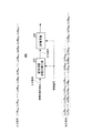
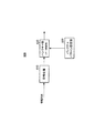
このとき、図1に示すように、送信する必要がある情報ビット数(例えば、ヘッダ長)が、ブロック符号のブロック長に比べ短いような場合、ブロック長の残りの部分の情報ビットを“0”と仮定して、符号化を行い、パリティビットを生成する。 At this time, as shown in FIG. 1, when the number of information bits that need to be transmitted (for example, the header length) is shorter than the block length of the block code, the remaining information bits of the block length are set to “0”. Assuming "", encoding is performed to generate parity bits.
そして、実際に送信する符号化系列としては、例えば、図1に示すように、送信する必要がある情報ビット(例えば、ヘッダ)及びパリティビットのみを送信する。すなわち、“0”と仮定した情報ビットの部分は、実際には送信しないようにする。 As an encoded sequence to be actually transmitted, for example, as shown in FIG. 1, only information bits (for example, header) and parity bits that need to be transmitted are transmitted. That is, the information bit portion assumed to be “0” is not actually transmitted.
一般に、制御情報等のヘッダは、画像等の情報を伝送するペイロードデータに比べビット数が少ない。しかし、図1に示すようにして、ヘッダ及びパリティビットを送信するようにすることで、ヘッダとペイロードデータとを同一のブロック符号を用いて符号化することが可能となる。更に、ヘッダは、ヘッダ長より長いブロック長のブロック符号により符号化されるため、ヘッダの受信品質を確保することができる。この結果、ヘッダを通信相手に確実に伝送することができるようになるので、上述の通信方法は、通信を確立させるために有効である。
しかしながら、従来技術は、ヘッダのようにブロック長に比べデータ長が短いデータに対し、符号化を行うと、受信品質を向上することができるものの、情報ビットを“0”と仮定して符号化して得られたパリティビットをも送信しなくてはならない。そのため、ヘッダ長とブロック長とが同等で、その長さが短い場合には、送信しなければならないパリティビット数が少なくて済む。これに対し、従来技術は、ヘッダ長よりブロック長が長い場合には、送信しなければならないパリティビット数が増え、データの伝送効率が劣化してしまうという課題がある。したがって、データ伝送効率が劣化する点を改善すると、データ伝送効率の向上と、受信品質の向上との両立を図ることができるという利点をもつことになる。 However, although the conventional technique can improve the reception quality by encoding data having a data length shorter than the block length, such as a header, the encoding is performed assuming that the information bit is “0”. The parity bit obtained in this way must also be transmitted. Therefore, when the header length is equal to the block length and the length is short, the number of parity bits that need to be transmitted is small. On the other hand, the prior art has a problem that when the block length is longer than the header length, the number of parity bits to be transmitted increases, and the data transmission efficiency deteriorates. Therefore, improving the point where the data transmission efficiency deteriorates has an advantage that it is possible to achieve both improvement in data transmission efficiency and improvement in reception quality.
本発明はかかる点に鑑みてなされたものであり、例えば、QC−LDPC符号等のブロック符号を用いる場合に、受信品質を向上させつつ、伝送量を低減させ、伝送効率の劣化を抑圧することができる符号化器、送信装置及び符号化方法を提供することを目的とする。 The present invention has been made in view of the above points. For example, when a block code such as a QC-LDPC code is used, the reception quality is improved, the transmission amount is reduced, and the deterioration of the transmission efficiency is suppressed. An object of the present invention is to provide an encoder, a transmission device, and an encoding method.
本発明の符号化器は、情報ビットを入力し、前記情報ビットとQC−LDPCのパリティ生成行列との行列演算によりパリティビットを生成する符号化器であって、前記情報ビットにゼロを挿入し、前記情報ビット及び前記ゼロと、前記パリティ生成行列との行列演算により前記パリティビットを生成し、前記情報ビットを配置する位置と前記パリティ生成行列とに基づいて、前記パリティビットのうち、値が常にゼロとなるパリティビットを削除し、削除後のパリティ系列を出力する、構成を採る。 The encoder of the present invention is an encoder that inputs information bits and generates parity bits by matrix operation of the information bits and a parity generation matrix of QC-LDPC, and inserts zeros into the information bits. The parity bit is generated by a matrix operation of the information bit and the zero and the parity generation matrix, and the value of the parity bit is based on the position where the information bit is arranged and the parity generation matrix. A configuration is adopted in which parity bits that are always zero are deleted, and the deleted parity sequence is output.
本発明の送信装置は、上記符号化器を具備し、前記パリティビットのうち、前記値が常にゼロとなるパリティビット以外の前記パリティビットと、前記情報ビットとを送信する送信手段と、を具備する構成を採る。 A transmission apparatus according to the present invention includes the encoder, and includes transmission means for transmitting, out of the parity bits, the parity bits other than the parity bit whose value is always zero, and the information bits. The structure to do is taken.
本発明の符号化方法は、情報ビットを入力し、前記情報ビットとQC−LDPCのパリティ生成行列との行列演算によりパリティビットを生成する符号化方法であって、前記情報ビットにゼロを挿入し、前記情報ビット及び前記ゼロと、前記パリティ生成行列との行列演算によりパリティビットを生成し、前記情報ビットを配置する位置と前記パリティ生成行列とに基づいて、前記パリティビットのうち、値が常にゼロとなるパリティビットを削除し、削除後のパリティ系列を出力するようにした。 An encoding method according to the present invention is an encoding method that inputs a parity bit and generates a parity bit by a matrix operation of the information bit and a parity generation matrix of QC-LDPC, and inserts zero into the information bit. A parity bit is generated by matrix operation of the information bit and the zero and the parity generation matrix, and the value of the parity bit is always based on the position where the information bit is arranged and the parity generation matrix. The parity bit that becomes zero is deleted, and the parity sequence after deletion is output.
本発明の通信装置及び通信方法によれば、例えば、QC−LDPC符号等のブロック符号を用いる場合に、受信品質を向上させつつ、伝送量を低減させ、伝送効率の劣化を抑圧することができる。 According to the communication apparatus and the communication method of the present invention, for example, when a block code such as a QC-LDPC code is used, it is possible to improve the reception quality, reduce the transmission amount, and suppress the deterioration of the transmission efficiency. .
以下、本発明の実施の形態について、図面を参照して詳細に説明する。 Hereinafter, embodiments of the present invention will be described in detail with reference to the drawings.
(実施の形態1)
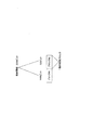
図2は、本発明の通信装置に用いられる符号化器の入出力データを示す。図2の符号化器100は、QC−LDPC(Quasi Cyclic Low Density Parity Check)符号を形成する。
(Embodiment 1)
FIG. 2 shows input / output data of an encoder used in the communication apparatus of the present invention. The
図2において、情報系列u=(x1,x2,…,xm)は、符号化器100の入力データであり、符号化系列s=(x1,x2,…,xm,p1,p2,…,pn)は、符号化器の出力データを示す。
In FIG. 2, an information sequence u = (x1, x2,..., Xm) is input data of the
式(1)は、QC−LDPC符号のパリティ検査行列Hを示す(非特許文献1、非特許文献2、非特許文献3参照)。

式(1)において、0≦j≦J−1、0≦l≦L−1であり、符号長N=p×L(pは自然数)のパリティ検査行列Hである。また、サブブロック行列I(pj,l)は、q行r列(r=(q+pj,l)mod p(0≦q≦p−1))が1であり、その他は“0”であるような巡回置換行列である。なお、pj,lは、乱数により“0”又は“1”に決定される。 In equation (1), 0 ≦ j ≦ J−1, 0 ≦ l ≦ L−1, and a parity check matrix H of code length N = p × L (p is a natural number). In the sub-block matrix I (p j, l ), q rows and r columns (r = (q + p j, l ) mod p (0 ≦ q ≦ p−1)) are 1, and the others are “0”. It is a cyclic permutation matrix. Note that p j, l is determined to be “0” or “1” by a random number.
図2の符号化器100は、生成行列Gを用いて、符号化系列を生成する。ここで、生成行列Gは、パリティ検査行列Hと、式(2)の関係がある。
![]()
![]()
符号化系列sは、情報系列u及び生成行列Gより、sT=GuTと示すことができる。QC−LDPC符号は、組織符号であるので、生成行列Gは、式(3)のように示すことができる。
ここで、Iは、m×mの単位行列である。また、行列gは、符号化系列sのうち、パリティ系列wのみを取り出し、w=(p1,p2,…,pn)と定義した場合に、パリティ系列wを求めるための行列(パリティ生成行列)である。パリティ生成系列wは、wT=guTを満たす。 Here, I is an m × m unit matrix. The matrix g is a matrix (parity generation matrix) for obtaining the parity sequence w when only the parity sequence w is extracted from the encoded sequence s and defined as w = (p1, p2,..., Pn). It is. The parity generation sequence w satisfies w T = gu T.
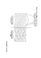
図3は、QC−LDPC符号のパリティ生成行列gの一例を示す。図3に示すQC−LDPC符号は、非特許文献4のTable 20-14(LDPC parameters)に記載の符号化率(Coding rate(R))=1/2,LDPC符号情報ブロック長(LDPC code information block length(bits))=648,LDPC符号語ブロック長(LDPC codeword block length(bits))=1296のQC−LDPC符号である。
FIG. 3 shows an example of the parity generation matrix g of the QC-LDPC code. The QC-LDPC code shown in FIG. 3 has a coding rate (Coding rate (R)) = 1/2, LDPC code information block length (LDPC code information block length) described in Table 20-14 (LDPC parameters) of
図3に示すパリティ生成行列gは、複数のサブブロック行列201,202,…,211,212,…から構成される。例えば、図3のサブブロック行列201において、(i+1)行目の各要素は、i行目の各要素を1ビット(1列)右にシフトした値をとる(iは自然数)。同様に、図3のサブブロック行列211において、(i+1)行目の各要素は、i行目の各要素を1ビット右にシフトした値をとる(iは自然数)。
3 includes a plurality of
また、図3のサブブロック行列202において、2行目の各要素は、1行目の各要素を1ビット右にシフトした値をとる。同様に、図3のサブブロック行列212において、2行目の各要素は、1行目の各要素を1ビット右にシフトした値をとる。
Further, in the
このように、サブブロック行列201,202,…,211,212は、巡回置換行列といえる。図3に示す例では、サブブロック行列201,202,…,211,212は、27行27列の行列である。
Thus, the
更に、パリティ生成行列gにおいて列が同一のサブブロック行列同士は、関連性を有している。例えば、サブブロック行列201と、サブブロック行列201と列が同一のサブブロック行列211とを比較すると、サブブロック行列211のi行目の要素は、サブブロック行列201の(i+1)行目の要素と2ビット目が異なるだけである(iは自然数)。
Further, sub-block matrices having the same column in the parity generation matrix g are related to each other. For example, when the
同様に、サブブロック行列202と、サブブロック行列202の列とが同一のサブブロック行列212とを比較すると、サブブロック行列212のi行目の要素は、サブブロック行列201の(i+1)行目の要素と同じである(iは自然数)。
Similarly, when the
なお、27行27列のサブブロック行列を縦に眺めた場合、例えば、サブブロック行列201とサブブロック行列211とを眺めた場合、上述したように、これらサブブロック行列は、関連性を有しているものの、必ずしも同一の行列であるとは限らない。
In addition, when the sub-block matrix of 27 rows and 27 columns is viewed vertically, for example, when the
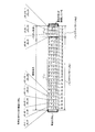
更に、パリティ生成行列gでは、要素“0”が連続して配置されるのが特徴的である。そのため、図3と同一のパリティ生成行列gを示す図4から分かるように、サブブロック行列202内に、行列を構成する要素が全て“0”の行列221を確保することができる。以下、行列を構成する要素が全て“0”の行列を、ゼロ行列と呼ぶ。
Further, the parity generation matrix g is characterized in that the elements “0” are continuously arranged. Therefore, as can be seen from FIG. 4 showing the same parity generation matrix g as in FIG. 3, a
また、サブブロック行列212内には、ゼロ行列221と同じ列から始まり、ゼロ行列221と列数が同じ大きさのゼロ行列222を確保することができる。ゼロ行列221と同じ列から始まり、ゼロ行列221と列数が同じ大きさのゼロ行列は、図示せぬパリティ生成行列g内に多数存在する。
In the
このように、QC−LDPC符号のパリティ生成行列は、ゼロ行列を含み、かつ、パリティ生成行列の同じ列から始まるゼロ行列が、多数存在するのが特徴的である。 Thus, the parity generation matrix of the QC-LDPC code includes a zero matrix and is characterized in that there are many zero matrices starting from the same column of the parity generation matrix.
本発明者らは、QC−LDPC符号のパリティ生成行列gのこの特徴に着目した。すなわち、m行n列のゼロ行列以外の列に情報ビットとして“0”を配置すると、生成されるm個のパリティビットが、全てゼロになることに着目した。更に、パリティ生成行列gにおいて列が同一のサブブロック行列同士は、要素の配列に関連性があり、QC−LDPC符号のパリティ生成行列gには、同じ列から始まるゼロ行列が多数存在するため、ゼロ行列以外の列に情報ビットとして“0”を配置することにより、全てゼロになるパリティビットが多数生成されることに着目した。 The inventors paid attention to this feature of the parity generation matrix g of the QC-LDPC code. That is, attention is paid to the fact that if “0” is arranged as an information bit in a column other than the zero matrix of m rows and n columns, all m parity bits to be generated become zero. Further, sub-block matrices having the same column in the parity generation matrix g are related to the arrangement of elements, and the parity generation matrix g of the QC-LDPC code includes a large number of zero matrices starting from the same column. It has been noted that by arranging “0” as an information bit in a column other than the zero matrix, many parity bits that are all zero are generated.
つまり、送信する必要がある情報ビット数が、ブロック符号のブロック長に比べ短く、一部の情報ビットを“0”と仮定して符号化する場合に、送信する必要がある情報ビットをゼロ行列(m行n列)の列に配置し、仮想ビットとして“0”をゼロ行列(m行n列)以外に配置すると、値が“0”となるm個のパリティビットが生成される。これらのパリティビットは、送信する必要がある情報ビットに依存せず、必ず“0”となる。 That is, when the number of information bits that need to be transmitted is shorter than the block length of the block code and encoding is performed assuming that some information bits are “0”, the information bits that need to be transmitted are zero matrix. When arranged in a column of (m rows and n columns) and “0” as a virtual bit other than a zero matrix (m rows and n columns), m parity bits having a value of “0” are generated. These parity bits are always “0” regardless of the information bits that need to be transmitted.
したがって、受信側は、ゼロ行列の位置から、値が必ず“0”のm個のパリティビットの位置が分かるので、送信側からは、値が必ず“0”のm個のパリティビットが送信せずとも、受信側は全てのデータの復号することができる。また、受信側は、値が必ず“0”のm個のパリティビット分を送信装置が送信しないビットと設定することができる、つまり、冗長ビットとして削減することができる。 Therefore, since the receiving side knows the position of m parity bits whose value is always “0” from the position of the zero matrix, the transmitting side must always transmit m parity bits whose value is “0”. At least, the receiving side can decode all data. In addition, the receiving side can set m parity bits whose values are always “0” as bits that are not transmitted by the transmitting apparatus, that is, reduce them as redundant bits.
再度、図4を用いて詳細に説明する。図4のゼロ行列221に着目する。図4のゼロ行列221は、7行12列の行列であり、ゼロ行列221の列に対応する情報ビットは、x36〜x47である。そこで、x36〜x47に、送信する必要のある情報ビットを配置し、x36〜x47以外に情報ビット“0”を配置して符号化を行うと、p1〜p7は、x36〜x47の値に関わらず、必ず“0”となる。
Again, it demonstrates in detail using FIG. Focus on the zero
同様に、パリティ生成行列gにおける列の位置が、ゼロ行列221と同じであるゼロ行列222に着目すると、x36〜x47以外に情報ビット“0”を配置して符号化を行うと、p28〜p34は、x36〜x47の値に関わらず、必ず“0”となる。
Similarly, paying attention to the zero
したがって、パリティ生成行列gにより生成されたパリティビットp1〜p54のうち、p1〜p7及びp28〜p34は、値が必ず“0”となる。このため、送信装置が、パリティ生成行列gにより生成された、これら値が必ず“0”となるパリティビットp1〜p54を送信しないようにすると、送信装置が送信する必要があるビットとしては、x36〜x47及びp8〜p27,p35〜p54のみとすることができる。なお、以上の説明では、一例として、p1〜p54に着目して説明したが、p55以降についても同様に考えることで、送信装置が送信するパリティビットの数の削減を行うことができる。 Accordingly, among the parity bits p1 to p54 generated by the parity generation matrix g, the values of p1 to p7 and p28 to p34 are always “0”. For this reason, if the transmission device does not transmit the parity bits p1 to p54 generated by the parity generation matrix g and whose values are always “0”, the bit that the transmission device needs to transmit is x36. -X47 and p8-p27, p35-p54 only. In the above description, as an example, the description has been made by paying attention to p1 to p54. However, the number of parity bits transmitted by the transmission device can be reduced by similarly considering p55 and the subsequent steps.
図4のゼロ行列221は、7行12列であるため、送信する必要がある情報ビットが12ビット以下の場合には、ゼロ行列221の列に送信する必要がある情報ビットを配置すれば良い。
Since the zero
なお、送信する必要がある情報ビットが、12ビットを超える場合には、例えば、図5に示すように、更にゼロ行列231,232…の列に送信する必要がある情報ビットを配置するようにすれば良い。QC−LDPC符号のパリティ生成行列の特徴として、“0”が連続して配置されているため、図5に示すように、パリティ生成行列gには、ゼロ行列221,222…以外にも、ゼロ行列231,232のようなゼロ行列が多数存在する。
When the information bits that need to be transmitted exceed 12 bits, for example, as shown in FIG. 5, the information bits that need to be transmitted are arranged in the columns of the zero
ゼロ行列231,232は、7行7列の行列であり、x71〜x77に送信する必要がある情報ビットを配置した場合においても、p1〜p7及びp28〜p34が全て“0”となる。そのため、送信装置は、ゼロ行列221,222を用いる場合と同様に、p1〜p7及びp28〜p34を送信しなくても良い。
The zero
したがって、ゼロ行列221,222に加え、ゼロ行列231,232を利用する場合には、送信する必要がある情報ビットを、x36〜x47及びx71〜x77に配置することができる。これにより、最大ビット数が、19(=12+7)ビットとなり、ゼロ行列221,222のみを利用する場合に比べ、送信する必要がある情報ビットとして配置可能な最大ビット数を増加することができる。
Therefore, when the zero
同様に、送信する必要がある情報ビット数が、19ビットを超える場合には、他の部分行列に含まれるゼロ行列を利用すれば良い。図5には、QC−LDPC符号のパリティ生成行列gの一部だけを示しており、QC−LDPCのパリティ生成行列gには、27行27列の巡回置換行列が列方向に24(=648/27)個存在するため、図示せぬ領域にもゼロ行列が多数含まれている。このため、送信装置は、ゼロ行列の部分において、上記と同様にゼロ行列を利用して、送信する必要がある情報ビットとして、配置することができる最大ビット数を増やすことができる。 Similarly, when the number of information bits that need to be transmitted exceeds 19 bits, a zero matrix included in another submatrix may be used. FIG. 5 shows only a part of the parity generation matrix g of the QC-LDPC code. In the parity generation matrix g of the QC-LDPC, a cyclic permutation matrix of 27 rows and 27 columns has 24 (= 648) in the column direction. Since there are / 27), a large number of zero matrices are included in a region not shown. For this reason, the transmission apparatus can increase the maximum number of bits that can be arranged as information bits that need to be transmitted in the zero matrix portion using the zero matrix in the same manner as described above.
このように、QC−LDPC符号のパリティ生成行列gには、パリティ生成行列gの同じ列から始まり、列数が同一のゼロ行列が、複数存在することに着目し、本実施の形態では、ゼロ行列の列に送信する必要がある情報ビットを配置し、ゼロ行列以外の列に仮想ビットとして“0”を配置する。これにより、ゼロ行列の行数と同じ数だけ値が“0”となるパリティビットが生成されるようになる。 Thus, paying attention to the fact that the parity generation matrix g of the QC-LDPC code includes a plurality of zero matrices starting from the same column of the parity generation matrix g and having the same number of columns. An information bit that needs to be transmitted is arranged in a matrix column, and “0” is arranged as a virtual bit in a column other than the zero matrix. As a result, parity bits having a value “0” by the same number as the number of rows of the zero matrix are generated.
このとき、送信装置及び受信装置は、パリティ生成行列gに対するゼロ行列の位置を共有していれば、このゼロ行列の行に対応するパリティビットを実際に送信せずとも、受信側では“0”が送信されたとして復号処理を行うことにより、パリティ生成行列gにより符号化された符号化データを復号することができる。このため、送信装置は、送信する必要があるパリティビット数を低減し、伝送効率を向上させることができる。 At this time, if the transmitting apparatus and the receiving apparatus share the position of the zero matrix with respect to the parity generation matrix g, “0” is set on the receiving side without actually transmitting the parity bit corresponding to the row of the zero matrix. By performing the decoding process assuming that is transmitted, the encoded data encoded by the parity generation matrix g can be decoded. For this reason, the transmission apparatus can reduce the number of parity bits that need to be transmitted, and improve the transmission efficiency.
なお、ゼロ行列は、1行1列であっても良い。すなわち、同一行に1行1列のゼロ行列が複数あり、この複数のゼロ行列と同一列の要素がゼロの行があれば、同一列において要素がゼロとなる行数分だけ、常に“0”となるパリティビットが生成されることになる。 The zero matrix may be 1 row and 1 column. That is, if there are a plurality of zero matrices of one row and one column in the same row and there are rows in which the elements in the same column as the plurality of zero matrices are zero, the number of rows in which the elements are zero in the same column is always “0 A parity bit of “is generated.
すなわち、送信装置は、情報ビットにゼロを挿入し、情報ビット及びゼロと、QC−LDPC符号のパリティ生成行列との行列演算によりパリティビットを生成する場合において、情報ビットを配置する位置とパリティ生成行列とに基づいて、パリティビットのうち、値が常にゼロとなるパリティビットを削除し、削除後のパリティ系列を出力し、削除後のパリティ系列を送信するようにすることで、送信する必要があるパリティビット数を低減し、伝送効率を向上させることができる。 That is, when the transmitter inserts zeros into information bits and generates parity bits by matrix operation of the information bits and zeros and the parity generation matrix of the QC-LDPC code, the position where the information bits are arranged and the parity generation Based on the matrix, it is necessary to delete the parity bits whose values are always zero, output the deleted parity sequence, and transmit the deleted parity sequence. It is possible to reduce the number of parity bits and improve transmission efficiency.
なお、送信装置は、パリティ生成行列gの同じ列から始まり、列数が同一のゼロ行列(1行1列のゼロ行列も含む)のうち、行数が最も多い行列を、設定するゼロ行列とし、設定したゼロ行列の列以外に“0”を配置することにより、値が“0”となるパリティビットを、設定したゼロ行列の行数分だけ生成するようになる。 Note that the transmitting apparatus sets a matrix having the largest number of rows among zero matrices (including a zero matrix of one row and one column) starting from the same column of the parity generation matrix g and having the same number of columns as a zero matrix to be set. By arranging “0” other than the set zero matrix columns, parity bits having a value of “0” are generated by the number of rows of the set zero matrix.
したがって、送信装置は、値が”0”となるパリティビットを送信しないビットとしてパンクチャすることにより、伝送効率を向上させることができる。このとき、送信装置は、パリティ生成行列gの同じ列から始まり、列数が同一のゼロ行列のうち、パリティ生成行列gにより多く含まれるような部分行列をゼロ行列として設定することにより、パリティビットをより削減することができる。 Therefore, the transmission apparatus can improve the transmission efficiency by puncturing the parity bit having a value of “0” as a bit that is not transmitted. At this time, the transmission apparatus sets a partial matrix that starts from the same column of the parity generation matrix g and is included in the parity generation matrix g among the zero matrices having the same number of columns as a zero matrix. Can be further reduced.
なお、このとき、送信装置は、送信する必要がある情報ビットとして、配置することができる最大ビット数を、ゼロ行列の列数とする。例えば、送信装置は、ゼロ行列として、ゼロ行列221,222,…が設定された場合、送信する必要がある情報ビットを配置することができる最大ビット数は12ビットとなる。
At this time, the transmission apparatus sets the maximum number of bits that can be arranged as information bits that need to be transmitted as the number of columns of the zero matrix. For example, when zero
また、送信装置は、ゼロ行列として、ゼロ行列221,222に加え、ゼロ行列231,232が設定される場合には、送信する必要がある情報ビットを配置することができる最大ビット数は19ビットとなる。逆に言えば、送信装置は、送信する必要がある情報ビットのデータ長(ビット数)に応じて、ゼロ行列を設定するようすれば良い。なお、上述したように、ゼロ行列は、1行1列でも良く、また、連続していなくても良い。
In addition, when the zero
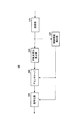
図6には、上述のようなパリティ生成行列gを用いて符号化を行う符号化器の構成例を示す。図6の符号化器100は、ゼロ行列設定部110、配置部120、符号化部130及びパンクチャ部(データ削減部)140を有する。以下では、ヘッダ等のように、データ長が一定の情報系列が、符号化器100に入力される場合を例に説明する。
FIG. 6 shows a configuration example of an encoder that performs encoding using the parity generation matrix g as described above. The
ゼロ行列設定部110は、QC−LDPCのパリティ生成行列gの部分行列であって、要素が全て“0”から構成されるゼロ行列を設定する。ゼロ行列の設定方法は、情報系列のデータ長がヘッダ等のように一意に決まっている場合、列数がヘッダ長以上のゼロ行列を設定する。なお、以下では、図4のゼロ行列221,222,…が、ゼロ行列として設定された場合を例に説明する。ゼロ行列設定部110は、パリティ生成行列gにおけるゼロ行列の位置の情報を、配置部120及びパンクチャ部(データ削減部)140に出力する。
The zero
配置部120は、ヘッダ等の情報系列を入力し、ゼロ行列設定部110から通知されるゼロ行列の位置の情報に基づいて、ゼロ行列の列に情報ビット(入力ビット)を配置し、ゼロ行列以外の列に仮想ビットとして“0”を配置する。
例えば、ゼロ行列設定部110からゼロ行列221,222の位置が通知された場合、配置部120は、ゼロ行列221の列x36〜x47に、情報ビット(入力ビット)を配置し、x36〜x47以外に、“0”を配置する。配置部120は、配置後のビットを符号化部130に出力する。
For example, when the positions of the zero
符号化部130は、パリティ生成行列gを用いて、配置部120から出力されるビットを符号化して符号化系列(情報ビット及びパリティビット)を取得する。符号化部130は、符号化系列をパンクチャ部(データ削減部)140に出力する。
The
パンクチャ部(データ削減部)140は、ゼロ行列設定部110から通知されるゼロ行列221,222の位置の情報に基づいて、符号化系列から、x36〜x47以外に配置された“0”を送信しないビットとしてパンクチャ(削除)する。
The puncture unit (data reduction unit) 140 transmits “0” arranged other than x36 to x47 from the encoded sequence based on the information on the positions of the zero
また、パンクチャ部(データ削減部)140は、ゼロ行列設定部110から通知されるゼロ行列221,222の位置の情報に基づいて、符号化系列から、ゼロ行列221,222の行に対応するパリティビットp1〜p7,p28〜p34,…を送信しないビットとしてパンクチャ(削除)する。
Further, the puncturing unit (data reduction unit) 140, based on the position information of the zero
パンクチャ部(データ削減部)140は、符号化系列から送信しないビットとしてパンクチャ(削除)したビット以外の符号化系列を、送信する必要があるビットとして出力する。 The puncturing unit (data reduction unit) 140 outputs encoded sequences other than the bits punctured (deleted) as bits that are not transmitted from the encoded sequences as bits that need to be transmitted.
図7は、上述した符号化器から送信された信号を復号する復号化器の構成例を示す。 FIG. 7 shows a configuration example of a decoder that decodes a signal transmitted from the encoder described above.
復号化器300は、固定対数尤度比挿入部310及びBP(Belief Propagation)復号部320を有している。
The
固定対数尤度比挿入部310は、図示せぬ対数尤度比算出部により算出される受信対数尤度比、及び、ゼロ行列の位置に関する情報を示す制御信号を入力し、ゼロ行列の位置に応じて、受信対数尤度比に既知の対数尤度比を挿入する。
Fixed log-likelihood
例えば、符号化側で、ゼロ行列221,222,…が用いられた場合、固定対数尤度比挿入部310には、x36〜x47及びp8〜p27,p35〜…に対応する受信対数尤度比LLRx36〜LLRx47,LLRp8〜LLRp27,LLRp35〜…が入力される。そこで、固定対数尤度比挿入部310は、x1〜x35,x48,…に対応する受信対数尤度比LLRx1〜LLRx35,LLRx48…,LLRp1〜LLRp7,LLRp28〜LLRp34を挿入する。
For example, when zero
具体的には、符号化側で、ゼロ行列221,222,…が用いられた場合、x1〜x35,x48,…、p1〜p7,p28〜p34,…として“0”が送信されていることに相当するので、固定対数尤度比挿入部310は、既知ビット“0”に対応する固定の対数尤度比を、x1〜x35,x48…の対数尤度比LLRx1〜LLRx35,LLRx48…,LLRp1〜LLRp7,LLRp28〜LLRp34…として挿入する。図7において、点線の丸で囲まれた受信対数尤度比は、固定対数尤度比挿入部310によって挿入された受信対数尤度比を示す。
Specifically, when zero
固定対数尤度比挿入部310は、挿入後の対数尤度比をBP復号部320に出力する。
Fixed log likelihood
BP復号部320は、例えば、非特許文献5から非特許文献7に記載されたsum-product復号、min-sum復号、Normalized BP復号、offset BP復号などを用いて、復号する。
The
以下には、上述のように構成された符号化器を有する通信装置#1の構成、及び、上述のように構成された復号化器を有し、通信装置#1から送信された信号を受信する通信装置#2の構成について説明する。
In the following, the configuration of the
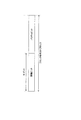
図8には、通信装置#1が送信する変調信号のフレーム構成例を示す。制御情報シンボルは、通信相手(通信装置#2)に、変調方式、使用している誤り訂正符号、符号化率、送信方法、データ長等の制御情報を伝送するためのシンボルである。情報シンボルは、QC−LDPC符号化により得られた情報ビット及びパリティビットを伝送するためのシンボルである。
FIG. 8 shows a frame configuration example of a modulated signal transmitted by
図9には、通信装置#1の構成例を示す。図9の通信装置400において、符号化部410は、情報系列を入力し、符号化系列をインタリーバ420に出力する。符号化部410は、図6の符号化器100によって構成されている。
FIG. 9 shows a configuration example of the
インタリーバ420は、符号化系列を入力し、インタリーブを行うことでインタリーブ後のデータを得る。なお、符号の種類によっては、インタリーバ420を設けなくても良い。
The
マッピング部430は、インタリーブ後のデータを入力し、QPSK(Quadrature Phase Shift Keying)、16QAM(Quadrature Amplitude Modulation)等の変調を行うことでベースバンド信号を得る。
The
送信部440は、ベースバンド信号を入力し、直交変調、周波数変換等の所定の信号処理を施すことで変調信号を得、変調信号を送信する。
The
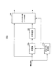
図10は、通信装置#2の構成例を示す。図10の通信装置500において、受信部510は、受信信号を入力し、周波数変換等の所定の無線処理を施すことでベースバンド信号を得る。受信部510は、ベースバンド信号を、制御情報検出部520及び対数尤度比算出部530に出力する。
FIG. 10 shows a configuration example of the
制御情報検出部520は、ベースバンド信号からゼロ行列に関する情報、インタリーブパターンの情報、符号化率に関する情報等を検出する。そして、制御情報検出部520は、インタリーブパターンの情報をデインタリーバ540に出力し、ゼロ行列に関する情報及び符号化率に関する情報を復号化部550に出力する。
The control
対数尤度比算出部530は、ベースバンド信号を入力し、例えば非特許文献5に示されている方法を用いることで対数尤度比を算出し、ビットごとの対数尤度比を得る。対数尤度比算出部530は、ビットごとの対数尤度比をデインタリーバ540に出力する。
The log-likelihood
デインタリーバ540は、ビットごとの対数尤度比を入力し、インタリーバ420に対応するデインタリーブの処理を施すことでデインタリーブ後の対数尤度比を得る。なお、復号化部550は、BP復号を行う場合に、デインタリーバ540を設けなくても、デインタリーブを考慮した検査行列を用意することで、復号することが可能である。
The
復号化部550は、図7の復号化器300によって構成されている。復号化部550は、デインタリーブ後の対数尤度比を入力し、符号化部410に対応する復号を行うことで受信データを得る。
The
以上のように、本実施の形態では、ゼロ行列設定部110は、パリティ生成行列gの部分行列であって、要素が全て“0”のゼロ行列を設定する。配置部120は、ゼロ行列の列に入力ビットを配置し、ゼロ行列以外の列に“0”を配置する。符号化部130は、パリティ生成行列gを用いて符号化してパリティビットを取得する。パンクチャ部(データ削減部)140は、ゼロ行列設定部110から通知されるゼロ行列の位置の情報に基づいて、ゼロ行列以外の列に配置された“0”を送信しないビットとしてパンクチャ(削除)し、更に、得られたパリティビットのうち、ゼロ行列の行に対応するパリティビットを、送信しないビットとしてパンクチャ(削除)する。
As described above, in the present embodiment, the zero
これにより、符号化器100は、情報ビットを入力し、情報ビットとパリティ生成行列との行列演算によりパリティビットを生成する場合において、パリティ生成行列のうち、要素が全てゼロの部分行列の列に対応する位置に情報ビットを配置し、要素が全てゼロの部分行列以外の列に対応する位置にゼロを配置し、配置後の情報ビット及びゼロと、パリティ生成行列との行列演算をする。これにより、符号化器100は、パリティ系列を生成し、パリティ系列のうち、値が常にゼロとなるパリティビットを削除し、削除後のパリティ系列を出力する。
As a result, the
換言すると、符号化器100は、情報ビットにゼロを挿入し、情報ビット及びゼロと、QC−LDPCのパリティ生成行列との行列演算によりパリティビットを生成し、ゼロを挿入する位置及びパリティ生成行列とに基づいて、パリティビットのうち、値が常にゼロとなるパリティビットを削除し、削除後のパリティ系列を出力する。
In other words, the
したがって、符号化器100を有する送信装置400において、送信部440が、入力ビットと、パリティビットのうち、ゼロ行列の行に対応する前記パリティビット以外と、を送信することにより、ゼロ行列の行に対応するパリティビットを受信側に送信せずとも、受信側では、ゼロ行列の行に対応するパリティビットの対数尤度比として既知の固定の対数尤度比を挿入して、復号を行うことができるため、送信するパリティビット数を低減し、伝送効率を向上させることができる。
Therefore, in the
なお、送信する必要がある情報ビットは、制御情報等を含むヘッダに限られず、ペイロードデータ(情報伝送用のシンボル)等であっても良い。要するに、送信する必要がある情報ビットの数が、QC−LDPC符号に含まれるゼロ行列の列数に比べ小さければ、本発明を適用することができる。送信する必要がある情報ビットがヘッダであり、ヘッダ長が固定の場合には、ゼロ行列設定部110は、ヘッダ長に応じて予め最適なゼロ行列を設定しておくことができる。
The information bits that need to be transmitted are not limited to headers that include control information or the like, but may be payload data (symbols for information transmission) or the like. In short, the present invention can be applied if the number of information bits that need to be transmitted is smaller than the number of columns of the zero matrix included in the QC-LDPC code. When the information bit that needs to be transmitted is a header and the header length is fixed, the zero
一方、送信する必要がある情報ビットが、ペイロードデータの場合には、コンテンツ情報等の大きさによりデータ長が変動する。本発明は、送信する必要がある情報ビットのデータ長が、例えば、ペイロードデータのように変動する場合においても適用することができる。以下の実施の形態2では、送信する必要がある情報ビットのデータ長が変動する場合について説明する。 On the other hand, when the information bits that need to be transmitted are payload data, the data length varies depending on the size of the content information and the like. The present invention can also be applied to the case where the data length of information bits that need to be transmitted varies, for example, as payload data. In the following second embodiment, a case where the data length of information bits that need to be transmitted fluctuates will be described.
(実施の形態2)
本実施の形態では、送信する必要がある情報ビットのデータ長が変動する場合に、本発明を適用した場合の形態について説明する。
(Embodiment 2)
In the present embodiment, a case will be described in which the present invention is applied when the data length of information bits that need to be transmitted fluctuates.
図11は、QC−LDPC符号を用いた場合の1ブロックの構成例を示す。QC−LDPC符号は、ブロック符号であり、図11に示すように、1ブロックは、情報ビットとパリティビットとから構成される。ここで、1ブロック内の情報ビットのビット数がMビットであるとする。 FIG. 11 shows a configuration example of one block when a QC-LDPC code is used. The QC-LDPC code is a block code. As shown in FIG. 11, one block is composed of information bits and parity bits. Here, it is assumed that the number of information bits in one block is M bits.
図12は、本実施の形態に係る符号化器の構成例を示す。なお、図12の本実施の形態に係る符号化器において、図6と共通する構成部分には、図6と同一の符号を付して説明を省略する。図12の符号化器100aは、図6の符号化器100に対し、ゼロ行列設定部110及び配置部120に代えて、ゼロ行列設定部110a及び配置部120aを有している。以下では、Nビットの情報系列が符号化器100aに入力される場合を例に説明する。
FIG. 12 shows a configuration example of the encoder according to the present embodiment. In the encoder according to the present embodiment in FIG. 12, the same components as in FIG. 6 are assigned the same reference numerals as those in FIG. The
ゼロ行列設定部110aは、情報系列として入力される情報ビット(入力ビット)のデータ長Nに応じて、ゼロ行列を設定する。具体的には、ゼロ行列設定部110aは、先ず、情報ビット(入力ビット)のデータ長Nをカウントする。そして、ゼロ行列設定部110aは、データ長NをQC−LDPC符号の1ブロックあたりの情報ビット長Mで除算し、商β及び余りαを算出する。
The zero
配置部120aは、除算の結果、N=kM(kは整数)が成立する場合、図13に示すように、k個の全てのブロックの情報ビットの領域に、情報系列として入力される情報ビット(入力ビット)を配置する必要がある。すなわち、k個のブロックでは、QC−LDPC符号のパリティ生成行列gの全ての列に各情報ビット(入力ビット)を配置する必要がある。そのため、N=kM(kは自然数)が成立する場合は、ゼロ行列設定部110aは、ゼロ行列を設定せず、パリティ生成行列gの全ての列に情報ビット(入力ビット)を配置するよう配置部120aに指示信号を出力する。
When N = kM (k is an integer) is established as a result of the division, the
配置部120aは、除算の結果、N≠kM=βM+α(kは整数、α及びβは自然数)が成立する場合、図13に示すように、β個のブロックの情報ビットの領域には、情報ビット(入力ビット)を配置し、1個のブロック(特殊ブロック)の情報ビットの領域には、αビットの情報ビット(入力ビット)を配置する必要がある。すなわち、配置部120aは、β個のブロックでは、QC−LDPC符号のパリティ生成行列gの全ての列に各情報ビットを配置し、特殊ブロックでは、実施の形態1で述べたように、ゼロ行列の列に情報ビット(入力ビット)を配置するようにする必要がある。
When N ≠ kM = βM + α (k is an integer, α and β are natural numbers) as a result of the division, as shown in FIG. 13, the
そのため、N≠kM=βM+α(k、α及びβは自然数)が成立する場合には、ゼロ行列設定部110aは、特殊ブロックで送信する必要がある情報ビット(入力ビット)のデータ長αに応じて、ゼロ行列を設定する。このとき、ゼロ行列設定部110aは、データ長αの値に応じて、設定するゼロ行列を切り替える。具体的には、ゼロ行列設定部110aは、余りαと所定の閾値との比較結果に応じて、設定するゼロ行列を切り替える。上述したように、符号化器100aは、ゼロ行列によって、送信する必要がある情報ビットとして配置できるビット数の最大値が変動する。
Therefore, when N ≠ kM = βM + α (k, α, and β are natural numbers) holds, the zero
なお、図13では、特殊ブロックを時間的に最後に配置しているが、配置位置はこれに限ったものではない。 In FIG. 13, the special block is arranged last in time, but the arrangement position is not limited to this.
以下、図14を用いて、データ長に応じてゼロ行列を設定する動作について説明する。図14は、ゼロ行列設定部110aが、2つの閾値をa1、a2を有し、データ長αと2つの閾値との比較結果に応じて、ゼロ行列を切り替える場合の例である。送信しないビットとしてパンクチャできる(削減できる)パリティビット数は、ゼロ行列の行数と同じであるため、ゼロ行列を切り替えることは、換言すると、送信するパリティビットの削減方法を切り替えることになる。
Hereinafter, the operation of setting the zero matrix according to the data length will be described with reference to FIG. FIG. 14 shows an example in which the zero
0<α≦a1の場合、ゼロ行列#1(削減方法#1)により、送信するパリティビットを削減する。例えば、0<α≦a1(=12)の場合、ゼロ行列設定部110aは、ゼロ行列221,222…をゼロ行列として設定する。
When 0 <α ≦ a1, the parity bits to be transmitted are reduced by the zero matrix # 1 (reduction method # 1). For example, in the case of 0 <α ≦ a1 (= 12), the zero
そして、α=10の場合、配置部120aは、10ビットの情報に“0”を2ビット加え、12ビットにする。そして、配置部120aは、この12ビットを、x36〜x47に割り当て、x1〜x35,x48〜に“0”を割り当てる。この結果、符号化部130により得られるパリティビットのうち、パリティビットp1〜p7,p28〜p34,…は、x36〜x47の値によらず常に“0”となる。
When α = 10, the
したがって、パンクチャ部(データ削減部)140が、常に“0”となるパリティビットp1〜p7,p28〜p34を送信しないビットとしてパンクチャすることにより、復号特性を劣化させることなく、伝送効率を向上させることができる。 Therefore, the puncture unit (data reduction unit) 140 punctures the parity bits p1 to p7 and p28 to p34 that are always “0” as non-transmitted bits, thereby improving the transmission efficiency without degrading the decoding characteristics. be able to.
また、x36〜x47以外のビット(x1〜x35,x48〜)には、既知ビット“0”が割り当てられているので、パンクチャ部(データ削減部)140は、これらx36〜x47以外のビットもパンクチャする(送信しないビットと設定する)。加えて、α=10の場合には、パンクチャ部(データ削減部)140が、x36〜x47に割り当てられた2ビットの“0”を送信しないビットとしてパンクチャする(送信しないビットと設定する)。これにより、伝送効率を更に向上させることができる。 In addition, since a known bit “0” is assigned to bits (x1 to x35, x48 to) other than x36 to x47, the puncture unit (data reduction unit) 140 also punctures bits other than x36 to x47. Yes (set as a bit not to be sent). In addition, when α = 10, the puncture unit (data reduction unit) 140 punctures the 2-bit “0” assigned to x36 to x47 as a bit that is not transmitted (set as a bit that is not transmitted). Thereby, the transmission efficiency can be further improved.
例えば、配置部120aが、x46,x47に“0”を割り当てた場合に、パンクチャ部(データ削減部)140が、x46,x47をパンクチャすることにより、送信系列は、x36〜x45、パリティp8〜p27,p35〜p54,…となり、伝送効率を更に向上させることができる。
For example, when the
a1<α≦a2の場合、ゼロ行列#2(削減方法#2)により、送信するパリティビットを削減する。例えば、a1=12,a2=19の場合、ゼロ行列設定部110aは、ゼロ行列221,222,…に加え、ゼロ行列231,232,…を、ゼロ行列として設定する。
When a1 <α ≦ a2, the parity bits to be transmitted are reduced by the zero matrix # 2 (reduction method # 2). For example, in the case of a1 = 12, a2 = 19, the zero
そして、α=15の場合、配置部120aは、15ビットの情報に“0”を4ビット加え、19ビットにする。そして、配置部120aは、この19ビットを、x36〜x47及びx71〜x77に割り当て、x1〜x35,x48〜x71,x78〜に“0”を割り当てる。この結果、符号化部130により得られるパリティビットのうち、パリティビットp1〜p7,p28〜p34,…は、x36〜x47の値によらず常に“0”となる。
When α = 15, the
したがって、パンクチャ部(データ削減部)140は、常に“0”となるパリティビットp1〜p7,p28〜p34を送信しないビットとしてパンクチャすることにより、復号特性を劣化させることなく、伝送効率を向上させることができる。 Therefore, the puncture unit (data reduction unit) 140 punctures the parity bits p1 to p7 and p28 to p34 that are always “0” as non-transmitted bits, thereby improving the transmission efficiency without degrading the decoding characteristics. be able to.
また、x36〜x47,x71〜x77以外のビット(x1〜x35,x48〜x71,x78〜)には既知ビット“0”が割り当てられているので、パンクチャ部(データ削減部)140は、これらx36〜x47,x71〜x77以外のビットをパンクチャする(送信しないビット)と設定する。加えて、α=15の場合には、パンクチャ部(データ削減部)140が、x36〜x47,x71〜x77のいずれかに割り当てられた4ビットの“0”を送信しないビットとしてパンクチャする(送信しないビットと設定する)。 Further, since bits other than x36 to x47, x71 to x77 (x1 to x35, x48 to x71, x78, and so on) are assigned with a known bit “0”, the puncture unit (data reduction unit) 140 uses these x36. Bits other than ˜x47, x71 to x77 are set to be punctured (bits not to be transmitted). In addition, when α = 15, the puncture unit (data reduction unit) 140 punctures the 4-bit “0” assigned to any of x36 to x47 and x71 to x77 as a bit to be transmitted (transmission) Not set a bit).
これにより、送信装置は、伝送効率を更に向上させることができる。例えば、配置部120aが、x74〜x77に“0”を割り当てた場合に、パンクチャ部(データ削減部)140が、x74〜x77をパンクチャすることにより、送信系列は、x36〜x45、x71〜x73、p8〜p27,p35〜p54,…となり、送信装置は、伝送効率を更に向上させることができる。
Thereby, the transmission device can further improve the transmission efficiency. For example, when the
なお、図14に示す例では、a2<α≦M−1の場合、ゼロ行列を設定せず、パリティビットの削減は行わないようにした。すなわち、情報ビット(入力ビット)のデータ長Nをブロック長Mで除算した余りαが所定の閾値以上の場合には、α個の情報ビット(入力ビット)、及び、仮想ビットとして(M−α)個の“0”を、パリティ生成行列gの列に配置するようにする。 In the example shown in FIG. 14, when a2 <α ≦ M−1, the zero matrix is not set, and the parity bit is not reduced. That is, when the remainder α obtained by dividing the data length N of information bits (input bits) by the block length M is equal to or greater than a predetermined threshold value, α information bits (input bits) and virtual bits (M−α) ) Pieces of “0” are arranged in the columns of the parity generation matrix g.
このようにして、ゼロ行列設定部110aは、特殊ブロックで送信する必要がある情報ビット(入力ビット)のデータ長αに応じて、ゼロ行列を設定する。そして、ゼロ行列設定部110aは、パリティ生成行列gにおけるゼロ行列の位置の情報を配置部120a及びパンクチャ部(データ削減部)140に通知する。
In this way, the zero
なお、ゼロ行列設定部110aは、a2<α≦M−1の場合、ゼロ行列を設定せず、パリティビットの削減は行わないようにした。そのため、そのため、a2<α≦M−1の場合、ゼロ行列設定部110aは、パリティビットをパンクチャしないようパンクチャ部(データ削減部)140に通知する。
Note that the zero
以上のように、本実施の形態では、ゼロ行列設定部110aは、パリティ生成行列gの部分行列であって、要素が全て“0”のゼロ行列を、情報ビット(入力ビット)のデータ長Nに応じて設定するようにした。このようにすることで、送信装置は、送信する必要があるパリティビット数を低減しつつ、情報ビット(入力ビット)を確実に送信することができる。
As described above, in the present embodiment, the zero
なお、図14には、余りαの値に応じて、3つのいずれかに場合分けをする例を示したが、場合分け数は3つに限られない。例えば、ゼロ行列設定部110aが、閾値を更に有し、Z個に場合分けするようにしても良い。
Although FIG. 14 shows an example in which the case is divided into three according to the value of the remainder α, the number of cases is not limited to three. For example, the zero
また、本実施の形態を実現するにあたり、復号化器を具備する受信装置が、余りαの値を知っている必要がある。これを実現する簡単な方法としては、符号化器を具備する送信装置が、送信するデータのビット数の情報を、最初に受信装置に通知すれば良い。なおこのとき、受信装置は、αを求めるための演算部を具備する必要がある。 In order to realize the present embodiment, it is necessary that the receiving apparatus including the decoder knows the remainder α. As a simple method for realizing this, a transmitting apparatus including an encoder may first notify the receiving apparatus of information on the number of bits of data to be transmitted. At this time, the receiving apparatus needs to include an arithmetic unit for obtaining α.
(実施の形態3)
本実施の形態では、QC−LDPC符号におけるパンクチャ方法について説明する。
(Embodiment 3)
In this embodiment, a puncturing method in the QC-LDPC code will be described.
図15は、本実施の形態に係る符号化器の構成例を示す。図15の符号化器600は、符号化部610、パンクチャパターン設定部620及びパンクチャ部(データ削減部)630を有している。
FIG. 15 shows a configuration example of the encoder according to the present embodiment. The
符号化部610は、QC−LDPCのパリティ生成行列gを用いて、情報系列に符号化を行う。
パンクチャパターン設定部620は、QC−LDPC符号の検査行列Hが、サブブロック行列を基本単位として構成されていることを利用して、パンクチャパターンを探索し、設定する。パンクチャパターンの探索方法については、後述する。パンクチャパターン設定部620は、設定したパンクチャパターンの情報を、パンクチャ部(データ削減部)630に出力する。
The puncture
パンクチャ部(データ削減部)630は、パンクチャパターン設定部620から通知されるパンクチャパターンに従って、符号化部610から出力される符号化系列のうち、送信しないビットとして情報ビット又はパリティビットをパンクチャする(送信しないビットと設定する)。
The puncturing unit (data reduction unit) 630 punctures information bits or parity bits as non-transmitted bits in the encoded sequence output from the
次に、パンクチャパターン設定部620が設定するパンクチャパターンの探索方法について説明する。パンクチャパターンは、QC−LDPC符号の検査行列Hが、サブブロック行列を基本単位として構成されていることを利用して、パンクチャパターンを探索する。
Next, a puncture pattern search method set by the puncture
パンクチャパターン設定部620は、パンクチャパターンを探索する際、先ず、パンクチャパターンの周期を決定する。例えば、20ビットから送信しないビット(パンクチャビット)をKビット選択する場合、パンクチャパターンの周期は、20ビットとなる。なおこのとき、パンクチャパターンの周期の20ビット内に含まれる送信しないビット(パンクチャビット)の数は、K個とし、常に一定とする。
When searching for a puncture pattern, the puncture
本発明では、パンクチャパターンの周期を、QC−LDPC符号の検査行列の基本単位であるサブブロック行列I(pj,l)(q行r列(r=(q+pj,l)mod p(0≦q≦p−1)が1であり、その他は“0”であるような巡回置換行列)の列数Lの整数倍、又は、列数Lの約数とする(式(1)参照)。 In the present invention, the period of the puncture pattern is determined by subblock matrix I (p j, l ) (q row r column (r = (q + p j, l ) mod p (0)) , which is the basic unit of the check matrix of the QC-LDPC code. ≦ q ≦ p−1) is 1, and the other is a cyclic permutation matrix such that “0” is an integer multiple of the number of columns L) or a divisor of the number of columns L (see Expression (1)). .
例えば、図3に示すQC−LDPC符号の検査行列におけるサブブロック行列は、27行27列(L=27)の行列であるので、27の整数倍、又は、27の約数をパンクチャパターンの周期と設定し、送信しないビット(パンクチャビット)K個を設定することを提案する。 For example, since the sub-block matrix in the parity check matrix of the QC-LDPC code shown in FIG. 3 is a matrix of 27 rows and 27 columns (L = 27), an integer multiple of 27, or a divisor of 27 is the period of the puncture pattern It is proposed to set K bits not to be transmitted (puncture bits).
一般に、ブロック符号では、ブロック長が長いほど良好な受信特性が得られる。しかし、ブロック長が長い場合には、ブロック長単位で、最良のパンクチャパターンを探索することは困難である。そのため、ブロック長が長い場合には、ランダムにパンクチャビットを選択する方式の採用が考えられる。しかし、この場合には、パンクチャ時の受信品質が大きく劣化する可能性がある。 In general, with a block code, the longer the block length, the better the reception characteristics. However, when the block length is long, it is difficult to search for the best puncture pattern in block length units. For this reason, when the block length is long, it is conceivable to adopt a method of randomly selecting puncture bits. However, in this case, reception quality at the time of puncturing may be greatly degraded.
これに対し、パンクチャパターン設定部620が、QC−LDPC符号の検査行列Hを構成するサブブロック行列が規則的であることに着目し、サブブロック行列の列数の整数倍、又は、列数の約数ごとに、パンクチャパターンを探索する場合には、比較的短い時間で特性が良好となるパンクチャパターンを確実に見つけ出すことができる。
On the other hand, the puncture
パンクチャパターンの具体的な探索方法としては、例えば、所定のSNR(Signal-to-Noise power ratio:信号電力対雑音電力比)を設定し、パンクチャパターンごとに誤り率を求め、誤り率が低くなるパンクチャパターンを求めれば良い。 As a specific search method for a puncture pattern, for example, a predetermined SNR (Signal-to-Noise power ratio) is set, an error rate is obtained for each puncture pattern, and the error rate is lowered. Find a puncture pattern.
送信装置は、このようにして探索されたパンクチャパターンを用いて、符号化系列をパンクチャすることにより、良好な受信品質を維持しつつ、伝送効率を向上させることができる。すなわち、図15の構成で重要な点は、パンクチャ部(データ削減部)630は、符号化系列をQC−LDPC符号の検査行列Hを構成するサブブロック行列の列数の整数倍、又は、列数の約数を単位として、パンクチャを行っている点である。 The transmission device can improve transmission efficiency while maintaining good reception quality by puncturing the encoded sequence using the puncture pattern searched in this way. That is, the important point in the configuration of FIG. 15 is that the puncturing unit (data reduction unit) 630 is an integral multiple of the number of columns of the sub-block matrix constituting the parity check matrix H of the QC-LDPC code, or Puncture is performed in units of divisors of numbers.
一例として、パンクチャ部(データ削減部)630が、パンクチャパターンの周期をサブブロック行列の列数Lとし、サブブロック行列の列数Lごとに、送信しないビット(パンクチャビット)の数をK個と一定とする場合について説明する。この場合、パンクチャ部(データ削減部)630は、パンクチャパターンを、QC−LDPC符号の検査行列Hを構成するサブブロック行列の列数の整数倍ごとに切り替える。 As an example, the puncture unit (data reduction unit) 630 sets the period of the puncture pattern as the number L of columns of the subblock matrix, and sets the number of bits (puncture bits) not transmitted for each number of columns L of the subblock matrix as K. The case where it is assumed to be constant will be described. In this case, puncture section (data reduction section) 630 switches the puncture pattern for each integer multiple of the number of columns of the sub-block matrix that constitutes check matrix H of the QC-LDPC code.
パンクチャパターンの切り替え方法について、図16A〜図16Cを用いて具体的に説明する。 A puncture pattern switching method will be specifically described with reference to FIGS. 16A to 16C.
図16Aは、図3の検査行列Hに対し、サブブロック行列の列数(列数の1倍)ごとにパンクチャパターンを切り替える様子を示している。図3の検査行列Hは、27列のサブブロック行列から構成されるため、パンクチャ部(データ削減部)630は、x1〜x27に対しては、パンクチャパターン#0を用いて送信しないビット(パンクチャビット)をK個選択する。また、パンクチャ部(データ削減部)630は、x28〜x54に対してはパンクチャパターン#1を用いて、送信しないビット(パンクチャビット)をK個選択する。また、パンクチャ部(データ削減部)630は、p622〜p648に対しては、パンクチャパターン#23を用いて、送信しないビット(パンクチャビット)をK個選択する。
FIG. 16A shows a state in which the puncture pattern is switched for each number of columns of the sub-block matrix (one times the number of columns) with respect to the parity check matrix H of FIG. 3 is composed of 27 sub-block matrices, puncturing section (data reduction section) 630 does not transmit bits (punctures) using
図16Bは、図3の検査行列Hに対し、サブブロック行列の列数の2倍ごとにパンクチャパターンを切り替える様子を示している。図3の検査行列Hは、27列のサブブロック行列から構成されるため、パンクチャ部(データ削減部)630は、x1〜x27,x28〜x54に対しては、パンクチャパターン#0を用いて送信しないビット(パンクチャビット)をK個選択する。
FIG. 16B shows a state in which the puncture pattern is switched every two times the number of columns of the sub-block matrix with respect to the parity check matrix H of FIG. 3 is composed of a 27-column sub-block matrix, puncture section (data reduction section) 630 transmits
また、パンクチャ部(データ削減部)630は、x55〜x81,x82〜x108に対してはパンクチャパターン#1を用いて、送信しないビット(パンクチャビット)をK個選択する。また、パンクチャ部(データ削減部)630は、x109〜x135,x136〜x162に対しては、パンクチャパターン#2を用いて、送信しないビット(パンクチャビット)をK個選択する。
The puncture unit (data reduction unit) 630 uses
図16Cは、図3の検査行列Hに対し、サブブロック行列の列数の約数9列を基本周期として、9列ごとにパンクチャパターンを切り替える様子を示している。具体的には、パンクチャ部(データ削減部)630は、x1〜x9に対しては、パンクチャパターン#0を用いて送信しないビット(パンクチャビット)をK個選択する。
FIG. 16C shows a state in which the puncture pattern is switched every 9 columns with respect to the parity check matrix H of FIG. Specifically, puncturing section (data reduction section) 630 selects K bits (puncture bits) that are not transmitted using
パンクチャ部(データ削減部)630は、x10〜x18に対しては、パンクチャパターン#1を用いて送信しないビット(パンクチャビット)をK個選択する。パンクチャ部(データ削減部)630は、x19〜x27に対しては、パンクチャパターン#2を用いて送信しないビット(パンクチャビット)をK個選択する。
The puncture unit (data reduction unit) 630 selects K bits (puncture bits) that are not transmitted using the
同様に、パンクチャ部(データ削減部)630は、x28〜x36に対しては、パンクチャパターン#3を用いて送信しないビット(パンクチャビット)をK個選択する。パンクチャ部(データ削減部)630は、x37〜x45に対しては、パンクチャパターン#4を用いて送信しないビット(パンクチャビット)をK個選択する。パンクチャ部(データ削減部)630は、x46〜x54に対しては、パンクチャパターン#5を用いて送信しないビット(パンクチャビット)をK個選択する。
Similarly, the puncture unit (data reduction unit) 630 selects K bits (puncture bits) that are not transmitted using
同様に、パンクチャ部(データ削減部)630は、x622〜x630に対しては、パンクチャパターン#69を用いて送信しないビット(パンクチャビット)をK個選択する。パンクチャ部(データ削減部)630は、x631〜x639に対しては、パンクチャパターン#70を用いて送信しないビット(パンクチャビット)をK個選択する。パンクチャ部(データ削減部)630は、x640〜x648に対しては、パンクチャパターン#71を用いて送信しないビット(パンクチャビット)をK個選択する。
Similarly, puncture section (data reduction section) 630 selects K bits (puncture bits) that are not transmitted using puncture pattern # 69 for x622 to x630. The puncture unit (data reduction unit) 630 selects K bits (puncture bits) that are not transmitted using
なお、パンクチャ部(データ削減部)630は、パンクチャパターン#0〜#2から構成されるパンクチャパターン#S0を定義し、x1〜x27に、パンクチャパターン#S0を用いて送信しないビット(パンクチャビット)を3K個選択するようにしても良い。同様に、パンクチャ部(データ削減部)630は、パンクチャパターン#3〜#5から構成されるパンクチャパターン#S1を定義し、x28〜x54に、パンクチャパターン#S1を用いて送信しないビット(パンクチャビット)を3K個選択するようにしても良い。
The puncture unit (data reduction unit) 630 defines a puncture pattern # S0 composed of
同様に、パンクチャ部(データ削減部)630は、パンクチャパターン#69〜#71から構成されるパンクチャパターン#S23を定義し、x622〜x648に、パンクチャパターン#S23を用いて送信しないビット(パンクチャビット)を3K個選択するようにしても良い。 Similarly, puncture section (data reduction section) 630 defines puncture pattern # S23 composed of puncture patterns # 69 to # 71, and bits (puncture bits) that are not transmitted using puncture pattern # S23 in x622 to x648 ) May be selected.
すなわち、サブブロック行列の列数の約数を基本周期としてパンクチャをすることは、QC−LDPC符号の検査行列Hを構成するサブブロック行列の列数を単位(周期)としてパンクチャすることと等価になる。 That is, puncturing with a divisor of the number of columns of the sub-block matrix as a basic period is equivalent to puncturing with the number of columns of the sub-block matrix constituting the parity check matrix H of the QC-LDPC code as a unit (period). Become.
以上のように、本実施の形態では、パンクチャパターン設定部620は、QC−LDPC符号の検査行列Hを構成するサブブロック行列の列数の整数倍、又は、列数の約数ごとにパンクチャパターンを探索し、パンクチャ部(データ削減部)630は、QC−LDPC符号の検査行列を構成するサブブロック行列の列数の整数倍、又は、列数の約数ごとに、パンクチャパターンを切り替える。これにより、良好な受信品質が得られるパンクチャパターンを、比較的短い時間で確実に探索することができ、良好な受信品質を維持しつつ、伝送効率を向上させることができる。
As described above, in the present embodiment, puncture
なお、以上の説明では、QC−LDPC符号の検査行列を構成するサブブロック行列の列数の整数倍、又は、列数の約数ごとに、パンクチャパターンを切り替える場合を例に説明したが、パンクチャパターンを必ずしも切り替える必要はない。 In the above description, the case where the puncture pattern is switched for each integer multiple of the number of columns of the sub-block matrix constituting the parity check matrix of the QC-LDPC code or every divisor of the number of columns has been described as an example. It is not always necessary to switch patterns.
例えば、図16Aは、「パンクチャパターン#0」、「パンクチャパターン#1」、・・・「パンクチャパターン#23」が同一のパンクチャパターンであっても良い。また、図16Bは、「パンクチャパターン#0」、「パンクチャパターン#1」、「パンクチャパターン#2」、・・・が同一のパンクチャパターンであっても良い。
For example, in FIG. 16A, “puncture
また、図16Cは、「パンクチャパターン#0」、「パンクチャパターン#1」、・・・「パンクチャパターン#71」が同一のパンクチャパターンであっても良い。要するに、パンクチャパターンの単位は、QC−LDPC符号の検査行列を構成するサブブロック行列の列数の整数倍、又は、列数の約数となっていれば良い。
In FIG. 16C, “puncture
(実施の形態4)
本実施の形態では、実施の形態1及び実施の形態2において説明した符号化方法を、制御情報に利用する場合の符号化方法の例を説明する。
(Embodiment 4)
In the present embodiment, an example of an encoding method when the encoding method described in
一例として、以下では、Coding rate(R)=1/2,LDPC code information block length(bits)=168,LDPC codeword block length(bits)=336のQC−LDPC符号を用い、200ビットの制御情報を符号化する場合について説明する。 As an example, QC-LDPC code of Coding rate (R) = 1/2, LDPC code information block length (bits) = 168, LDPC codeword block length (bits) = 336 is used below, and 200-bit control information is used. A case of encoding will be described.
図17は、200ビットの制御情報を168ビットと32ビットとに分割し、168ビットをブロック#1に配置し、32ビットをブロック#2に配置する場合を示している。図17において、ブロック#2には、ブロック長168ビットに対し、制御情報が32ビットしか配置されない。
FIG. 17 shows a case where 200-bit control information is divided into 168 bits and 32 bits, 168 bits are arranged in
以下、ブロック#2のように、送信する必要があるビットが、ブロック長より短いブロックは、実施の形態2において説明した特殊ブロックである。そのため、実施の形態2と同様に、ブロック#2では、情報ビットとして“0”が仮想ビットとして配置され、符号化される。この結果、ブロック#1とブロック#2とでは、受信品質にばらつきが発生し、結局、200ビットの制御情報の受信品質は、受信品質が悪いブロックに依存してしまう。
Hereinafter, the block whose bit that needs to be transmitted is shorter than the block length, such as the
そこで、本実施の形態では、図18に示すように、200ビットの制御情報を、2つのブロック#1,#2にできるだけ均等に配置し、各ブロックに対し実施の形態1で述べた符号化を行う。具体的には、制御情報が200ビットの場合、ブロック#1及びブロック#2の双方に、100ビットずつ制御情報を配置する。
Therefore, in the present embodiment, as shown in FIG. 18, 200-bit control information is arranged as evenly as possible in the two
これにより、ブロック#1及びブロック#2が共に、特殊ブロックになるため、ブロック#1及びブロック#2の双方で、情報ビットとして“0”が仮想ビットとして配置されて、実施の形態1における符号化方法により符号化される。これにより、ブロック#1とブロック#2との受信品質が均等になり、通信相手に的確に伝送できるようになる。
As a result, both the
なお、制御情報が201ビットの場合には、ブロック#1には制御情報を101ビット配置し、ブロック#2には制御情報を100ビット配置するようにする。この場合、ブロック#1における制御情報のビットの数とブロック#2における制御情報のビットの数との差は、高々1ビットである。このように、送信装置は、2つのブロックに、送信する必要がある情報をできるだけ均等に配置することにより、各ブロック間の受信品質を均等にすることができるので、制御情報を通信相手に確実に伝送することができるようになる。
When the control information is 201 bits, 101 bits of control information are arranged in
以上のように、本実施の形態では、制御情報を複数のブロックにできるだけ均等に配置するようにした。これにより、送信装置は、配置後の各ブロックに対し、実施の形態1において説明した符号化方法を適用することにより、制御情報等の通信確立に必要な情報を確実に通信相手に伝送することができる。 As described above, in this embodiment, control information is arranged as evenly as possible in a plurality of blocks. As a result, the transmission apparatus reliably transmits information necessary for establishing communication such as control information to the communication partner by applying the encoding method described in the first embodiment to each block after arrangement. Can do.
なお、本実施の形態における特殊ブロックの生成方法は、実施の形態2で説明した特殊ブロックの生成方法と同様である。つまり、送信装置は、送信する必要のない情報ビット及びパリティビットの双方を送信しないビットと設定(パンクチャビットと設定)することになる。 The special block generation method in the present embodiment is the same as the special block generation method described in the second embodiment. That is, the transmission apparatus sets (sets as a puncture bit) a bit that does not transmit both information bits and parity bits that do not need to be transmitted.
(実施の形態5)
本実施の形態では、QC−LDPC符号の一例を示すとともに、当該QC−LDPC符号に最適なパンクチャパターンについて説明する。
(Embodiment 5)
In the present embodiment, an example of a QC-LDPC code will be shown, and a puncture pattern optimum for the QC-LDPC code will be described.
QC−LDPC符号の検査行列Hは、式(4)のように定義する。
式(4)の検査行列Hは、m行n列の行列である。ここで、nは、符号長であり、mは、パリティビット数である。従って、システマティックビット数kは、k=n−mとなる。また、式(4)において、Pi,jは、z行z列の巡回置換行列又はz行z列のゼロ行列である。 The parity check matrix H in Equation (4) is a matrix with m rows and n columns. Here, n is the code length, and m is the number of parity bits. Therefore, the number k of systematic bits is k = n−m. In Equation (4), P i, j is a z-by-z cyclic permutation matrix or a z-by-z zero matrix.
ここで、式(4)の検査行列Hは、nb行mb列の行列Hbにより展開する。なお、m=z×mb、n=z×nbの関係が成り立つ。また、行列Hbの各要素は、Pi,jにおいて要素が“1”の場合、“1”とし、Pi,jにおいて要素が“0”の場合、“0”とする。 Here, the parity check matrix H of Equation (4) is expanded by a matrix H b of n b rows and m b columns. Incidentally, m = z × m b, the relationship of n = z × n b holds. Further, each element of the matrix H b in the case of P i, elements in j "1", and "1", the case of P i, elements in j "0", and "0".
ここで、Pi,jは、巡回置換行列として、z行z列の単位行列、又は、z行z列の単位行列を巡回シフトした行列の集合である。巡回置換行列は、単位行列、又は、単位行列を巡回シフトした行列の集合であるので、行列Hbを、行列Hbと大きさが同一の行列Hbmに分解すると、行列Hbmは、ゼロ行列、又は、単位行列を巡回シフトした行列で示される。 Here, P i, j is a set of matrices obtained by cyclically shifting a unit matrix of z rows and z columns or a unit matrix of z rows and z columns as a cyclic permutation matrix. Cyclic permutation matrix is a unit matrix, or, since it is a set of cyclic shifted matrix unit matrix, the matrix H b, the matrix H b and sizes are decomposed into the same matrix H bm, matrix H bm is zero It is indicated by a matrix or a matrix obtained by cyclically shifting a unit matrix.
なお、以降、行列Hbmにおいて、ゼロ行列は“−1”と標記する。また、単位行列は“0”と標記する。また、単位行列の巡回置換行列は、その巡回シフト量p(i,j)(>0)を用いて“p(i,j)”と標記する。このようにコンパクトに標記された行列Hbmの集合として、行列Hbを表現することができる。 Hereinafter, in the matrix H bm , the zero matrix is denoted as “−1”. The unit matrix is denoted as “0”. The cyclic permutation matrix of the unit matrix is denoted as “p (i, j)” using the cyclic shift amount p (i, j) (> 0). The matrix H b can be expressed as a set of the matrix H bm marked compactly in this way.
ところで、行列Hbは、式(5)に示すように、2つのサブ行列Hb1,Hb2に分けられる。サブ行列Hb1は、情報ビットに関連する部分行列であり、サブ行列Hb2は、パリティビットに関連する部分行列である。
![]()
![]()
サブ行列Hb2は、式(6)に示すように、更に、ベクトルhbとサブ行列H’b2に分けられる。
式(6)において、サブ行列H’b2は、i行j列(i=j及びi=j+1)の部分が“1”であり、他の部分は“0”の行列である。サブ行列H’b2において、“1”と標記される部分は、単位行列のシフト量が0であることを示す。つまり、サブ行列H’b2は、行列Hbに展開される際、z行z列の単位行列によって置き換えられる。 In Expression (6), the sub-matrix H ′ b2 is a matrix in which the portion of i rows and j columns (i = j and i = j + 1) is “1”, and the other portion is “0”. In the sub-matrix H ′ b2 , the portion marked “1” indicates that the shift amount of the unit matrix is zero. That is, the sub-matrix H ′ b2 is replaced with a unit matrix of z rows and z columns when expanded into the matrix H b .
また、ベクトルhbの一番上(hb(0))と一番下(hb(mb−1))とには、同じ巡回シフト量が割り当てられるとする。 Further, it is assumed that the same cyclic shift amount is assigned to the top (h b (0)) and the bottom (h b (m b −1)) of the vector h b .
以下では、式(7)により定義される行列Hbを考える。式(7)により定義される検査行列Hは、各符号化率における最大符号長に対応することができる。
式(7)において、p(f,i,j)は、単位行列の巡回シフト量を示し、fは、各符号化率に対応する符号長のインデックスを示す。また、zfは、展開ファクタと呼ばれ、zf=k/nの関係がある。 In Equation (7), p (f, i, j) represents the cyclic shift amount of the unit matrix, and f represents the code length index corresponding to each coding rate. Z f is called an expansion factor and has a relationship of z f = k / n.
式(7)に基づく符号化率1/2(=k/n)の行列Hbを、式(8)に示す。
式(8)において、“0”は、単位行列を示す。また、“−1”は、ゼロ行列を示す。また、たとえば、1行2列目の“94”は、単位行列を94だけサイクリックシフトした行列を示す。同様に、4行1列目の“61”は、単位行列を61だけサイクリックシフトした行列を示す。 In Expression (8), “0” indicates a unit matrix. “−1” indicates a zero matrix. For example, “94” in the first row and the second column indicates a matrix obtained by cyclically shifting the unit matrix by 94. Similarly, “61” in the 4th row and the 1st column indicates a matrix obtained by cyclically shifting the unit matrix by 61.
また、式(7)に基づく符号化率5/6(=k/n)の行列Hbを、式(9)に示す。
以上、符号化率1/2及び5/6のQC−LDPCの行列Hbの一例を示した。以下、これらQC−LDPCの行列Hbに適用可能なパンクチャパターンについて説明する。
Heretofore, an example of the QC-LDPC matrix Hb with
図19Aには、式(8)に示した符号化率1/2のQC−LDPCの行列Hbを示す。図19Aに示されるように、符号化率1/2の行列Hbは、情報ビットに関連する部分行列Hb1が12行であるため、パリティビットに関連する部分行列Hb2は12列となる。 FIG. 19A shows a QC-LDPC matrix Hb with a coding rate of 1/2 shown in equation (8). As shown in FIG. 19A, since the matrix H b with a coding rate of ½ has 12 rows of the partial matrix H b1 related to the information bits, the partial matrix H b2 related to the parity bits has 12 columns. .
図19Aのパリティビットに関連する部分行列Hb2は、1行1列目及び12行1列目を除き、“−1”,“0”で構成されており、規則的な配列となっている。上述したように、“−1”は、ゼロ行列を示し、“0”は、単位行列を示す。また、1行1列目及び12行1列目の“7”は、単位行列を7だけサイクリックシフトした巡回置換行列である。 The submatrix H b2 related to the parity bit in FIG. 19A is composed of “−1” and “0” except for the first row and the first column and the 12th row and the first column, and has a regular arrangement. . As described above, “−1” indicates a zero matrix, and “0” indicates a unit matrix. Further, “7” in the first row and the first column and the 12th row and the first column is a cyclic permutation matrix obtained by cyclically shifting the unit matrix by 7.
このとき、パリティビットに関連する部分行列Hb2の列において、単位行列、ゼロ行列により構成される部分は、同一のパンクチャパターンを用いるようにしても、受信品質に与える影響が低い。そのため、単位行列、ゼロ行列により構成される部分については、同一のパンクチャパターン#Aを用いても、良好な受信特性を得ることができる(図19A参照)。なお、単位行列、ゼロ行列により構成される部分に該当しない列については、異なるパンクチャパターンと設定するものとする。ただし、一部又は全てのパンクチャパターンが同一のパンクチャパターンとなっていても良い。 At this time, in the column of the partial matrix Hb2 related to the parity bit, even if the portion constituted by the unit matrix and the zero matrix uses the same puncture pattern, the influence on the reception quality is low. For this reason, good reception characteristics can be obtained even if the same puncture pattern #A is used for the portion constituted by the unit matrix and the zero matrix (see FIG. 19A). It should be noted that columns that do not correspond to the portion constituted by the unit matrix and the zero matrix are set as different puncture patterns. However, some or all of the puncture patterns may be the same puncture pattern.
更に、符号化系列は、実施の形態3で述べたパンクチャ方法と組み合わせることも可能である。つまり、符号化系列は、QC−LDPC符号の検査行列Hを構成するサブブロック行列の列数の整数倍、又は、列数の約数を単位として、パンクチャを行うと更に効果的である。図19B、図19Cでは、パリティビットに関連する部分行列Hb2に対し、QC−LDPC符号の検査行列Hを構成するサブブロック行列の列数の整数倍、又は、列数の約数を単位として、パンクチャを行う場合の例を示している。 Furthermore, the encoded sequence can be combined with the puncturing method described in the third embodiment. That is, the encoded sequence is more effective when puncturing is performed in units of an integer multiple of the number of columns of the sub-block matrix constituting the parity check matrix H of the QC-LDPC code or a divisor of the number of columns. In FIG. 19B and FIG. 19C, with respect to the partial matrix H b2 related to the parity bit, an integer multiple of the number of columns of the sub-block matrix constituting the parity check matrix H of the QC-LDPC code or a divisor of the number of columns is used as a unit. An example of performing puncturing is shown.
図19Bには、式(8)に示した符号化率1/2のQC−LDPCの行列Hb及びパンクチャパターンの別の適用例について示す。図19Bは、QC−LDPC符号の検査行列を構成するサブブロック行列の列数の整数倍(2倍)に、パンクチャパンターンの周期を設定した場合の例である。なお、図19Bは、単位行列、ゼロ行列により構成される部分には、同一のパンクチャパターン#Bを用いるようにした例である。
FIG. 19B shows another application example of the QC-LDPC matrix Hb and the puncture pattern of the
また、図19Cには、式(8)に示した符号化率1/2のQC−LDPCの行列Hb及びパンクチャパターンの別の適用例について示す。図19Cは、QC−LDPC符号の検査行列を構成するサブブロック行列の列数の1/2ごとにパンクチャパンターンを生成した場合の例である。なお、図19Cは、単位行列、ゼロ行列により構成される部分には、同一のパンクチャパターンを用いるようにした例である。
FIG. 19C shows another application example of the QC-LDPC matrix Hb and the puncture pattern of
具体的には、図19Cは、100行100列のサブブロック行列から構成される検査行列Hに対し、サブブロック行列の列数の1/2である約数50列を基本周期として、50列ごとにパンクチャパターンを切り替える様子を示している。 Specifically, FIG. 19C shows a check matrix H composed of 100-row 100-column sub-block matrix, with 50 columns with a divisor of 50 columns, which is 1/2 of the number of columns of the sub-block matrix, as a basic period. It shows how the puncture pattern is switched every time.
具体的には、パンクチャ部(データ削減部)630は、p100〜p149に対しては、パンクチャパターン#1を用いて送信しないビット(パンクチャビット)を選択する。パンクチャ部(データ削減部)630は、p150〜p199に対しては、パンクチャパターン#2を用いて送信しないビット(パンクチャビット)を選択する。パンクチャ部(データ削減部)630は、p200〜p249に対しては、パンクチャパターン#3を用いて送信しないビット(パンクチャビット)を選択する。
Specifically, the puncture unit (data reduction unit) 630 selects bits (puncture bits) that are not transmitted using
パンクチャ部(データ削減部)630は、p250〜p299に対しては、パンクチャパターン#4を用いて送信しないビット(パンクチャビット)を選択する。パンクチャ部(データ削減部)630は、p1100〜p1149に対しては、パンクチャパターン#21を用いて送信しないビット(パンクチャビット)を選択する。パンクチャ部(データ削減部)630は、p1150〜p1199に対しては、パンクチャパターン#22を用いて送信しないビット(パンクチャビット)を選択する。
The puncture unit (data reduction unit) 630 selects bits (puncture bits) that are not transmitted using
図20Aは、式(9)に示した符号化率5/6のQC−LDPCの行列Hbを示す。図20Aに示されるように、符号化率5/6の検査行列Hbは、情報ビットに関連する部分行列Hb1が4行であるため、パリティビットに関連する部分行列Hb2は4列となる。
FIG. 20A shows a QC-LDPC matrix Hb of the
図20Aのパリティビットに関連する部分行列Hb2は、1行1列目及び4行1列目を除き、“−1”,“0”で構成されており、規則的な配列となっている。また、1行1列目及び4行1列目の“80”は、単位行列を80だけサイクリックシフトした巡回置換行列である。 The submatrix H b2 related to the parity bit in FIG. 20A is composed of “−1” and “0” except for the first row and the first column and the fourth row and the first column, and has a regular arrangement. . Further, “80” in the first row and first column and the fourth row and first column is a cyclic permutation matrix obtained by cyclically shifting the unit matrix by 80.
このように、符号化率5/6の場合にも、パリティビットに関連する部分行列Hb2の列において、単位行列、ゼロ行列により構成される部分は、同一のパンクチャパターンを用いるようにしても、受信品質に与える影響が低い。そのため、単位行列、ゼロ行列により構成される部分の列については、同一のパンクチャパターン#Aを用いても、受信装置は、良好な受信特性を得ることができる(図20A参照)。なお、単位行列、ゼロ行列により構成される部分に該当しない列については、異なるパンクチャパターンと設定するものとするが、一部が同一のパンクチャパターンとなっていても良い。 As described above, even in the case of the coding rate of 5/6, in the column of the submatrix Hb2 related to the parity bit, the part constituted by the unit matrix and the zero matrix may use the same puncture pattern. The effect on reception quality is low. For this reason, the reception apparatus can obtain good reception characteristics even if the same puncture pattern #A is used for the columns of the part composed of the unit matrix and the zero matrix (see FIG. 20A). It should be noted that columns that do not correspond to the portion constituted by the unit matrix and the zero matrix are set as different puncture patterns, but some of them may be the same puncture pattern.
図20Bには、式(9)に示した符号化率5/6のQC−LDPCの行列Hb及びパンクチャパターンの別の適用例について示す。図20Bは、QC−LDPC符号の検査行列を構成するサブブロック行列の列数の整数倍(3倍)に、パンクチャパンターンの周期を設定した場合の例である。
FIG. 20B shows another application example of the QC-LDPC matrix Hb and the puncture pattern of the
また、図20Cには、式(9)に示した符号化率5/6のQC−LDPCの行列Hb及びパンクチャパターンの別の適用例について示す。図20Cは、QC−LDPC符号の検査行列を構成するサブブロック行列の列数の1/2ごとにパンクチャパンターンを生成した場合の例である。なお、図20Bと同様に、図20Cは、単位行列、ゼロ行列により構成される部分には、同一のパンクチャパターンを用いるようにした例である。
FIG. 20C shows another application example of the QC-LDPC matrix Hb and the puncture pattern of the
具体的には、図20Cは、100行100列のサブブロック行列から構成される検査行列Hに対し、サブブロック行列の列数の1/2である約数50列を基本周期として、50列ごとにパンクチャパターンを切り替える様子を示している。 Specifically, FIG. 20C shows a check matrix H composed of 100-row 100-column sub-block matrix, with 50 columns with a divisor of 50 columns, which is 1/2 of the number of columns of the sub-block matrix, as a basic period. It shows how the puncture pattern is switched every time.
具体的には、パンクチャ部(データ削減部)630は、p100〜p149に対しては、パンクチャパターン#1を用いて送信しないビット(パンクチャビット)を選択する。パンクチャ部(データ削減部)630は、p150〜p199に対しては、パンクチャパターン#2を用いて送信しないビット(パンクチャビット)を選択する。パンクチャ部(データ削減部)630は、p200〜p249に対しては、パンクチャパターン#3を用いて送信しないビット(パンクチャビット)を選択する。
Specifically, the puncture unit (data reduction unit) 630 selects bits (puncture bits) that are not transmitted using
パンクチャ部(データ削減部)630は、p250〜p299に対しては、パンクチャパターン#4を用いて送信しないビット(パンクチャビット)を選択する。パンクチャ部(データ削減部)630は、p300〜p349に対しては、パンクチャパターン#5を用いて送信しないビット(パンクチャビット)を選択する。パンクチャ部(データ削減部)630は、p350〜p399に対しては、パンクチャパターン#6を用いて送信しないビット(パンクチャビット)を選択する。
The puncture unit (data reduction unit) 630 selects bits (puncture bits) that are not transmitted using
このように、パリティビットに関連する部分行列Hb2の列において、単位行列、ゼロ行列により構成される部分は、同一のパンクチャパターンを設定し、単位行列、ゼロ行列により構成される部分に該当しない列については、異なるパンクチャパターンと設定する。 As described above, in the column of the submatrix H b2 related to the parity bit, the part constituted by the unit matrix and the zero matrix sets the same puncture pattern and does not correspond to the part constituted by the unit matrix and the zero matrix. For columns, set different puncture patterns.
なお、単位行列、ゼロ行列により構成される部分に該当しない列は、例えば、実施の形態3で述べたように、QC−LDPC符号の検査行列を構成するサブブロック行列の列数の整数倍、又は、列数の約数ごとに、パンクチャパターンを切り替えるようにしても良い。
In addition, as described in
また、単位行列、ゼロ行列により構成される部分に該当しない列は、パンクチャパターンのパターン長が、QC−LDPC符号の検査行列を構成するサブブロック行列の列数の整数倍、又は、列数の約数ごとである同一のパンクチャパターンを適用するようにしても良い。 In addition, a column that does not correspond to a part constituted by a unit matrix and a zero matrix has a pattern length of the puncture pattern that is an integer multiple of the number of columns of the sub-block matrix that constitutes the check matrix of the QC-LDPC code, or the number of columns The same puncture pattern that is every divisor may be applied.
(実施の形態6)
実施の形態5で説明したQC−LDPC符号を用い、かつ、実施の形態4で説明したQC−LDPC符号の検査行列を構成するサブブロック行列の列数の整数倍、又は、列数の約数を単位として、パンクチャを行っていて、全てにおいて、同一のパンクチャパターンを用いたときの例を示す。
(Embodiment 6)
An integer multiple of the number of columns of a sub-block matrix that uses the QC-LDPC code described in the fifth embodiment and constitutes the parity check matrix of the QC-LDPC code described in the fourth embodiment, or a divisor of the number of columns An example is shown in which puncturing is performed in units of and the same puncture pattern is used for all.
実施の形態6は、符号化率1/2の式(8)の検査行列をもつQC―LDPC符号からパンクチャにより、符号化率約0.65を実現するためのパンクチャパターンについて説明する。ただし、QC−LDPC符号の検査行列を構成するサブブロック行列のサイズは、行数350、列数350とする。したがって、QC−LDPC符号のInformation block length(bits)は4200となり、LDPC codeword block length(bits)は8400となる。
このとき、LDPC符号のcodewordを以下のようにあらわす。
v=[x0, x1, ・・・, x4198, x4199, p0, p1, ・・・, p4198, p4199]
=[s0, s1, s2, ・・・, s8397, s8398, s8399]
=[v0, v1, v2, ・・・, v167]
ただし、vはcodeword、xは情報、pはパリティを意味する。
At this time, the codeword of the LDPC code is expressed as follows.
v = [x0, x1, ..., x4198, x4199, p0, p1, ..., p4198, p4199]
= [s0, s1, s2, ・ ・ ・, s8397, s8398, s8399]
= [v0, v1, v2, ・ ・ ・, v167]
However, v means codeword, x means information, and p means parity.
なお、v0,v1,・・・,vi・・・,v167は以下のようにあらわされる。
v0=[s0, s1, ・・・, s48, s49]、
v1=[s50, s51, ・・・, s98, s99]、・・・、
vi=[s50*i, s50*i+1, ・・・, s50*i+48, s50*i+49]、・・・、
v167=[s8350, s8351, ・・・, s8398, s8399]
Note that v0, v1,..., Vi..., V167 are expressed as follows.
v0 = [s0, s1, ..., s48, s49],
v1 = [s50, s51, ..., s98, s99], ...
vi = [s50 * i, s50 * i + 1, ..., s50 * i + 48, s50 * i + 49], ...
v167 = [s8350, s8351, ・ ・ ・, s8398, s8399]
本発明者らは、パンクチャパターンを探索した結果、QC−LDPC符号の検査行列を構成するサブブロック行列の列数の約数である50をパンクチャパターンの周期とすると良好な受信品質を与えることを確認した。 As a result of searching for a puncture pattern, the inventors of the present invention provide good reception quality when the period of the puncture pattern is 50, which is a divisor of the number of columns of the sub-block matrix constituting the parity check matrix of the QC-LDPC code. confirmed.
良好な受信品質を与えるパンクチャリングパターンは以下のとおりである。
(1, 8, 19, 20, 25, 28, 29, 31, 38, 40, 41)
Puncturing patterns that give good reception quality are as follows.
(1, 8, 19, 20, 25, 28, 29, 31, 38, 40, 41)
別の表現として、パンクチャテーブルwは、
w=[1011111101 1111111110 0111101100 1011111101 0011111111]
であらわされる。
As another expression, the puncture table w is
w = [1011111101 1111111110 0111101100 1011111101 0011111111]
It is expressed.
このとき、wに含まれる0が送信しないビットを意味する。つまり、パンクチャテーブルwは、viに対して、図21に示すように送信しないビットを決定する。したがって、vi=[s50*i, s50*i+1, ・・・, s50*i+48, s50*i+49]に対して、送信しないビットを除いた、送信するデータビットvi’は、
vi’=[s50*i, s50*i+2, s50*i+3, s50*i+4, s50*i+5, s50*i+6, s50*i+7, s50*i+9,s50*i+10, s50*i+11, s50*i+12, s50*i+13, s50*i+14, s50*i+15, s50*i+16, s50*i+17, s50*i+18, s50*i+21, s50*i+22, s50*i+23, s50*i+24, s50*i+26, s50*i+27, s50*i+30, s50*i+32, s50*i+33, s50*i+34, s50*i+35, s50*i+36, s50*i+37, s50*i+39, s50*i+42, s50*i+43, s50*i+44, s50*i+45, s50*i+46, s50*i+47, s50*i+48, s50*i+49]とあらわされる。
At this time, 0 included in w means a bit that is not transmitted. That is, the puncture table w determines bits not to be transmitted for vi as shown in FIG. Therefore, for vi = [s50 * i, s50 * i + 1,..., S50 * i + 48, s50 * i + 49], the data bit vi ′ to be transmitted, excluding the bits not to be transmitted, is
vi '= [s50 * i, s50 * i + 2, s50 * i + 3, s50 * i + 4, s50 * i + 5, s50 * i + 6, s50 * i + 7, s50 * i + 9, s50 * i + 10, s50 * i + 11, s50 * i + 12, s50 * i + 13, s50 * i + 14, s50 * i + 15, s50 * i + 16, s50 * i + 17, s50 * i + 18, s50 * i + 21, s50 * i + 22, s50 * i + 23, s50 * i + 24, s50 * i + 26, s50 * i + 27, s50 * i + 30, s50 * i + 32, s50 * i + 33, s50 * i + 34, s50 * i + 35, s50 * i + 36, s50 * i + 37, s50 * i + 39, s50 * i + 42, s50 * i + 43, s50 * i + 44, s50 * i + 45, s50 * i + 46, s50 * i + 47, s50 * i + 48, s50 * i + 49].
符号化率5/6の式(9)の検査行列をもつQC―LDPC符号から、パンクチャにより、符号化率約0.95を実現するためのパンクチャパターンについて説明する。ただし、QC−LDPC符号の検査行列を構成するサブブロック行列のサイズは、行数210、列数210とする。したがって、QC−LDPC符号において、Information block length(bits)は4200となり、LDPC codeword block length(bits)は5040となる。 A puncture pattern for realizing a coding rate of about 0.95 by puncturing from a QC-LDPC code having a parity check matrix of equation (9) with a coding rate of 5/6 will be described. However, the size of the sub-block matrix constituting the check matrix of the QC-LDPC code is 210 rows and 210 columns. Therefore, in the QC-LDPC code, the information block length (bits) is 4200, and the LDPC codeword block length (bits) is 5040.
このとき、LDPC符号のcodewordを以下のようにあらわす。
v=[x0, x1, ・・・, x4198, x4199, p0, p1, ・・・, p838, p839]
=[s0, s1, s2, ・・・, s5037, s5038, s5039]
=[v0, v1, v2, ・・・, v79]
ただし、vはcodeword、xは情報、pはパリティを意味する。
At this time, the codeword of the LDPC code is expressed as follows.
v = [x0, x1, ..., x4198, x4199, p0, p1, ..., p838, p839]
= [s0, s1, s2, ・ ・ ・, s5037, s5038, s5039]
= [v0, v1, v2, ・ ・ ・, v79]
However, v means codeword, x means information, and p means parity.
なお、v0,v1,・・・,vi・・・,v79は以下のようにあらわされる。
v0=[s0, s1, ・・・, s61, s62]、
v1=[s63, s64, ・・・, s124, s125]、・・・、
vi=[s63*i, s63*i+1, ・・・, s63*i+61, s63*i+62]、・・・、
v79=[s4977, s4978, ・・・, s5038, s5039]。
V0, v1,..., Vi..., V79 are expressed as follows.
v0 = [s0, s1, ..., s61, s62],
v1 = [s63, s64, ..., s124, s125], ...,
vi = [s63 * i, s63 * i + 1, ..., s63 * i + 61, s63 * i + 62], ...
v79 = [s4977, s4978, ..., s5038, s5039].
本発明者らは、パンクチャパターンを探索した結果、63をパンクチャパターンの周期とすると良好な受信品質を与えることを確認した。 As a result of searching for a puncture pattern, the inventors of the present invention have confirmed that good reception quality is provided when 63 is a period of the puncture pattern.
良好な受信品質を与えるパンクチャリングパターンは以下のとおりである。
(3, 18, 20, 27, 39, 50, 60)
Puncturing patterns that give good reception quality are as follows.
(3, 18, 20, 27, 39, 50, 60)
別の表現として、パンクチャテーブルwは
w=[1110111111 1111111101 0111111011 1111111110 1111111111 0111111111 011]
であらわされる。
Another expression, puncture table w
w = [1110111111 1111111101 0111111011 1111111110 1111111111 0111111111 011]
It is expressed.
このとき、wに含まれる0が送信しないビットを意味する。つまり、パンクチャテーブルwは、viに対して、図22に示すように送信しないビットを決定する。したがって、vi=[s63*i, s63*i+1, ・・・, s63*i+61, s63*i+62]に対して送信しないビットを除いた、送信するデータビットvi’は、
vi’= [s63*i, s63*i+1, 63*i+2, s63*i+4, s63*i+5, s63*i+6, s63*i+7, s63*i+8, 63*i+9, s63*i+10, s63*i+11, s63*i+12, s63*i+13, s63*i+14, s63*i+15, s63*i+16, s63*i+17, s63*i+19, s63*i+21, s63*i+22, s63*i+23, s63*i+24, s63*i+25, s63*i+26, s63*i+28, s63*i+29, s63*i+30, s63*i+31, s63*i+32, s63*i+33, s63*i+34, s63*i+35, s63*i+36, s63*i+37, s63*i+38, s63*i+40, s63*i+41, s63*i+42, s63*i+43, s63*i+44, s63*i+45, s63*i+46, s63*i+47, s63*i+48, s63*i+49, s63*i+51, s63*i+52, s63*i+53, s63*i+54, s63*i+55, s63*i+56, s63*i+57, s63*i+58, s63*i+59, s63*i+61, s63*i+62]とあらわされる。
At this time, 0 included in w means a bit that is not transmitted. That is, the puncture table w determines bits not to be transmitted for vi as shown in FIG. Therefore, the data bits vi ′ to be transmitted, excluding the bits not transmitted with respect to vi = [s63 * i, s63 * i + 1,..., S63 * i + 61, s63 * i + 62],
vi '= (s63 * i, s63 * i + 1, 63 * i + 2, s63 * i + 4, s63 * i + 5, s63 * i + 6, s63 * i + 7, s63 * i + 8, 63 * i + 9, s63 * i + 10, s63 * i + 11, s63 * i + 12, s63 * i + 13, s63 * i + 14, s63 * i + 15, s63 * i + 16, s63 * i + 17, s63 * i + 19, s63 * i + 21, s63 * i + 22, s63 * i + 23, s63 * i + 24, s63 * i + 25, s63 * i + 26, s63 * i + 28, s63 * i + 29, s63 * i + 30, s63 * i + 31, s63 * i + 32, s63 * i + 33, s63 * i + 34, s63 * i + 35, s63 * i + 36, s63 * i + 37, s63 * i + 38, s63 * i + 40, s63 * i + 41, s63 * i + 42, s63 * i + 43, s63 * i + 44, s63 * i + 45, s63 * i + 46, s63 * i + 47, s63 * i + 48, s63 * i + 49, s63 * i + 51, s63 * i + 52, s63 * i + 53, s63 * i + 54, s63 * i + 55, s63 * i + 56, s63 * i + 57, s63 * i + 58, s63 * i + 59, s63 * i + 61, s63 * i + 62].
このとき、パンクチャパターンの周期を20〜90程度とすると、受信時のデータ品質が良好となる。なお、パンクチャパターンの周期とは、パンクチャパターンの最小周期をいう。例えば、パンクチャテーブルw1=[001]のパンクチャパターンの周期は3である。又、パンクチャテーブルw2=[001001]は、周期6の構成であるが、2つのパンクチャテーブルw1=[001]から構成され、パンクチャテーブルw1のパンクチャパターンの周期は3であるため、パンクチャテーブルw2のパンクチャパターンの(最小)周期は、パンクチャテーブルw1と同様に3である。すなわち、パンクチャパターンの周期とは、パンクチャパターンを構成するパターンのうち、最小パターンのパターン長をいう。また、パンクチャテーブルw3=[010]は、w1をサイクリックシフトしたものと同一となるが、上記のw, vi, vi’の関係を考慮すると、w3とw1は異なるパンクチャパターンということができる。すなわち、パンクチャテーブルwxとパンクチャテーブルwyがあったとき、たとえwxをサイクリックシフト(ただし、0ビットサイクリックシフトを除く)してwyと同一となってもwxとwyは異なるパンクチャパターンである。
At this time, if the period of the puncture pattern is about 20 to 90, the data quality at the time of reception is good. The period of the puncture pattern refers to the minimum period of the puncture pattern. For example, the period of the puncture pattern of the puncture table w1 = [001] is 3. Further, the puncture table w2 = [001001] has a configuration of
パンクチャパターンの周期が長すぎると、送信しないビット(パンクチャピット)の配置にランダム性が発生し、バイナリ消失チャネルにおいて、ランダムエラーが発生したモデルに近づくため、受信時のデータ品質は悪くなる。一方、パンクチャパターンの周期が短すぎると、送信しないビット(パンクチャピット)の配置が片寄るため、適切なパンクチャパターンとなる可能性が低くなり、受信時のデータ品質は悪くなる。このため、パンクチャパターンの周期を20〜90程度とすることが重要となる。 If the period of the puncture pattern is too long, randomness occurs in the arrangement of bits (puncture pits) that are not transmitted, and the binary erasure channel approaches a model in which a random error has occurred, resulting in poor data quality at the time of reception. On the other hand, if the period of the puncture pattern is too short, the arrangement of non-transmitted bits (puncture pits) is offset, so that the possibility of an appropriate puncture pattern is reduced, and the data quality at the time of reception deteriorates. For this reason, it is important to set the period of the puncture pattern to about 20 to 90.
また、パンクチャパターンの周期を20〜90程度とした際、パンクチャテーブルwに0が3つ以上含まれるようにすると、受信時のデータ品質は良好となる(受信(復号)時に良好なデータ品質を得ることができるパンクチャパターンを生成できる可能性が高くなる)。パンクチャテーブルwに0が3つ以上含まれると、送信しないビット(パンクチャピット)の配置に規則性がなくなりランダム性が増すため、受信時のデータ品質が良好となる。 Further, when the puncture pattern period is set to about 20 to 90, if the puncture table w includes three or more zeros, the data quality at the time of reception becomes good (good data quality at the time of reception (decoding). The possibility of generating a puncture pattern that can be obtained is increased). If the puncture table w includes three or more zeros, the arrangement of bits not transmitted (puncture pits) is not regular and randomness is increased, so that the data quality at the time of reception is good.
更に、パンクチャパターンの周期を20〜90程度とし、かつ、パンクチャテーブルwに0が3つ以上含まれるようにし、かつ、QC−LDPC符号の検査行列を構成するサブブロック行列の列数の整数倍、又は、列数の約数をパンクチャパターンの周期とすると、受信(復号)時に良好なデータ品質を得ることができるパンクチャパターンを生成できる可能性が高くなる。 Further, the period of the puncture pattern is set to about 20 to 90, and the puncture table w includes three or more zeros, and is an integer multiple of the number of columns of the sub-block matrix constituting the parity check matrix of the QC-LDPC code Or, if the divisor of the number of columns is the period of the puncture pattern, there is a high possibility that a puncture pattern capable of obtaining good data quality at the time of reception (decoding) can be generated.
上記以外におけるパンクチャパターンは以下のとおりである。
QC−LDPC符号の検査行列を構成するサブブロック行列のサイズは、行数80、列数80とし、符号化率1/2の式(8)の検査行列をもつQC―LDPC符号(Information block length(bits)=960, LDPC codeword block length(bits)=1920)からパンクチャにより、符号化率約0.65、0.75を実現するためのパンクチャパターンは以下のとおりである。
符号化率約0.65の場合:w=[1111110110 0100111111]
符号化率約0.75の場合:w=[1100111111 1101111110 0111110001 1110000111]
The puncture patterns other than the above are as follows.
The size of the sub-block matrix constituting the parity check matrix of the QC-LDPC code is 80 rows and 80 columns, and the QC-LDPC code (Information block length) having the parity check matrix of equation (8) with a coding rate of 1/2. Puncture patterns for realizing coding rates of about 0.65 and 0.75 by puncturing from (bits) = 960, LDPC codeword block length (bits) = 1920) are as follows.
When the coding rate is about 0.65: w = [1111110110 0100111111]
When the coding rate is about 0.75: w = [1100111111 1101111110 0111110001 1110000111]
QC−LDPC符号の検査行列を構成するサブブロック行列のサイズは、行数48、列数48とし、符号化率5/6の式(9)の検査行列をもつQC―LDPC符号(Information block length(bits)=960, LDPC codeword block length(bits)=1152)から、パンクチャにより、符号化率約0.95を実現するためのパンクチャパターンは以下のとおりである。
w= [1111111110 1111111111 0111101111 1111001111 11101111]
The size of the sub-block matrix constituting the parity check matrix of the QC-LDPC code is 48 rows and 48 columns, and the QC-LDPC code (Information block length) having the parity check matrix of equation (9) with a coding rate of 5/6. From (bits) = 960, LDPC codeword block length (bits) = 1152), a puncture pattern for realizing a coding rate of about 0.95 by puncturing is as follows.
w = [1111111110 1111111111 0111101111 1111001111 11101111]
QC−LDPC符号の検査行列を構成するサブブロック行列のサイズは、行数180、列数180とし、符号化率1/2の式(8)の検査行列をもつQC―LDPC符号(Information block length(bits)=2160, LDPC codeword block length(bits)=4320)からパンクチャにより、符号化率約0.65、0.75を実現するためのパンクチャパターンは以下のとおりである。
符号化率約0.65の場合:w=[1011111100 0011111101 1111100111 011111]
符号化率約0.75の場合:w=[1111110100 0001101001 1111111110]
The size of the sub-block matrix constituting the parity check matrix of the QC-LDPC code is 180 rows and 180 columns, and a QC-LDPC code (Information block length) having a parity check matrix of equation (8) with a coding rate of 1/2. Puncture patterns for realizing coding rates of about 0.65 and 0.75 by puncturing from (bits) = 2160, LDPC codeword block length (bits) = 4320) are as follows.
When coding rate is about 0.65: w = [1011111100 0011111101 1111100111 011111]
For coding rate of about 0.75: w = [1111110100 0001101001 1111111110]
QC−LDPC符号の検査行列を構成するサブブロック行列のサイズは、行数108、列数108とし、符号化率5/6の式(9)の検査行列をもつQC―LDPC符号Information block length(bits)=2160, LDPC codeword block length(bits)=2592)から、パンクチャにより、符号化率約0.95を実現するためのパンクチャパターンは以下のとおりである。
w= [1011111111 1111011111 1110111]
The size of the sub-block matrix constituting the parity check matrix of the QC-LDPC code is 108 rows and 108 columns, and the QC-LDPC code Information block length () having the parity check matrix of equation (9) with a coding rate of 5/6 is used. bits) = 2160, LDPC codeword block length (bits) = 2592), the puncture pattern for realizing the coding rate of about 0.95 by puncturing is as follows.
w = [1011111111 1111011111 1110111]
(実施の形態7)
実施の形態5では、パリティ検査行列Hbにおいて、単位行列及びゼロ行列により構成されるサブ行列H’b2(式(6)参照)とサブ行列H’b2以外のサブ行列(以下「H’b1(=Hb1+hb)」と標記する。式(5)及び(6)参照)とで、異なるパンクチャパターンを用いる場合について説明した。その一例として、実施の形態5では、図19A〜図19C、図20A〜図20Cに示すように、単位行列及びゼロ行列により構成されるサブ行列H’b2に、サブブロック行列の列数の整数倍、又は、列数の約数を単位として、同一のパンクチャパターンを用いる場合について説明した。
(Embodiment 7)
In the fifth embodiment, in the parity check matrix H b, matrix and submatrix H 'b2 (Equation (6) refer) and sub-matrix H' constituted by zero matrix b2 non sub-matrix (hereinafter "H 'b1 (= H b1 + h b ) ”(see formulas (5) and (6)), the case where different puncture patterns are used has been described. As an example, in the fifth embodiment, as shown in FIGS. 19A to 19C and FIGS. 20A to 20C, an integer of the number of columns of the sub-block matrix is added to the sub-matrix H ′ b2 composed of the unit matrix and the zero matrix. A case has been described where the same puncture pattern is used in units of multiples or divisors of the number of columns.
本実施の形態では、実施の形態5と同様に、パリティ検査行列Hbにおいて、単位行列及びゼロ行列により構成されるサブ行列H’b2とサブ行列H’b1とで、異なるパンクチャパターンを用いる場合について説明する。具体的には、図20Bに対応する図23に示すように、サブ行列H’b1には、サブ行列H’b1の列数をパンクチャ周期とするパンクチャパターン#p1を用い、サブ行列H’b2には、サブ行列H’b2の列数をパンクチャパターン周期とするパンクチャパターン#p2を用いて、符号化率20/21を実現する場合について説明する。
In the present embodiment, as in the fifth embodiment, in the parity check matrix H b , different puncture patterns are used for the sub-matrix H ′ b2 and the sub-matrix H ′ b1 configured by the unit matrix and the zero matrix. Will be described. Specifically, as illustrated in FIG. 23 corresponding to FIG. 20B, the sub-matrix H ′ b1 uses a puncture pattern # p1 in which the number of columns of the sub-matrix H ′ b1 is a puncture period, and the sub-matrix H ′ b2 in using the puncture patterns # p2 to the number of columns of submatrix H 'b2 and puncturing pattern period, the case of realizing a
以下では、一例として、符号化率5/6の式(9)の検査行列をもつQC―LDPC符号から、パンクチャにより、符号化率20/21を実現するためのパンクチャパターンについて説明する。 Hereinafter, as an example, a puncture pattern for realizing a coding rate of 20/21 by puncturing from a QC-LDPC code having a parity check matrix of Equation (9) with a coding rate of 5/6 will be described.
図24の検査行列Hbは、式(9)に示した符号化率5/6のQC−LDPCの検査行列Hbである。式(9)の検査行列Hbは、4行24列のサブブロック行列から構成される。なお、以下では、QC−LDPC符号の検査行列を構成するサブブロック行列のサイズが、行数48、列数48とする。したがって、QC−LDPC符号において、Information block length(bits)は960となり、LDPC codeword block length(bits)は1152となる。 Parity check matrix Hb in FIG. 24 is QC-LDPC parity check matrix Hb shown in Equation (9) with a coding rate of 5/6. The parity check matrix Hb of Equation (9) is composed of a 4 × 24 sub-block matrix. In the following, it is assumed that the size of the sub-block matrix constituting the parity check matrix of the QC-LDPC code is 48 rows and 48 columns. Therefore, in the QC-LDPC code, the information block length (bits) is 960, and the LDPC codeword block length (bits) is 1152.
このとき、LDPC符号のcodewordを以下のようにあらわす。
v=[x0, x1, ・・・, x958, x959, p0, p1, ・・・, p190, p191]
=[s0, s1, s2, ・・・, s1149, s1150, s1151]
=[v0, v1, v2, ・・・, v24]
ただし、vはcodeword、xは情報、pはパリティを意味する。
At this time, the codeword of the LDPC code is expressed as follows.
v = [x0, x1, ..., x958, x959, p0, p1, ..., p190, p191]
= [s0, s1, s2, ..., s1149, s1150, s1151]
= [v0, v1, v2, ・ ・ ・, v24]
However, v means codeword, x means information, and p means parity.
なお、v0,v1,・・・,vi・・・,v23は以下のようにあらわされる。
v0=[s0, s1, ・・・, s46, s47]、
v1=[s48, s48, ・・・, s94, s95]、・・・、
vi=[s48*i, s48*i+1, ・・・, s48*i+46, s48*i+47]、・・・、
v23=[s1104, s1105, ・・・, s1150, s1151]。
Note that v0, v1,..., Vi..., V23 are expressed as follows.
v0 = [s0, s1, ..., s46, s47],
v1 = [s48, s48, ..., s94, s95], ...
vi = [s48 * i, s48 * i + 1, ..., s48 * i + 46, s48 * i + 47], ...
v23 = [s1104, s1105, ..., s1150, s1151].
図24において、#0は、x0,x1,…,x47に対応する部分行列を示し、#1は、x48,x49,…,x95に対応する部分行列を示す。また、#21は、p48,p49,…,p95に対応する部分行列を示し、#22は、p96,p97,…,p143に対応する部分行列を示し、#23は、p144,p145,…,p191に対応する部分行列を示す。 In FIG. 24, # 0 indicates a partial matrix corresponding to x0, x1,..., X47, and # 1 indicates a partial matrix corresponding to x48, x49,. # 21 indicates a partial matrix corresponding to p48, p49,..., P95, # 22 indicates a partial matrix corresponding to p96, p97,..., P143, and # 23 indicates p144, p145,. The submatrix corresponding to p191 is shown.
図24において、サブ行列H’b1は、#0〜20により構成され、サブ行列H’b2は、#21,#22,#23により構成される。#21,#22,#23は、単位行列(“0”)及びゼロ行列(“−1”)により構成される。このように、式(9)に示すQC−LDPC符号の検査行列Hbは、単位行列及びゼロ行列で構成されるサブ行列H’b2を含んでいる。 In FIG. 24, the sub-matrix H ′ b1 is composed of # 0 to # 20, and the sub-matrix H ′ b2 is composed of # 21, # 22, and # 23. # 21, # 22, and # 23 are composed of a unit matrix (“0”) and a zero matrix (“−1”). Thus, the check matrix H b of the QC-LDPC code shown in Equation (9) includes a sub-matrix H ′ b2 composed of a unit matrix and a zero matrix.
本実施の形態では、サブ行列H’b2及びBP復号の特徴を考慮して好適なパンクチャパターンを以下のようにして決定する。 In the present embodiment, a suitable puncture pattern is determined as follows in consideration of the characteristics of the sub-matrix H ′ b2 and BP decoding.
BP復号では、行演算と列演算とを反復して各ビットの対数尤度比を得る。 In BP decoding, the logarithmic likelihood ratio of each bit is obtained by repeating the row operation and the column operation.
BP復号の行演算では、対数尤度比が更新される。このとき、送信されなかった(パンクチャ)ビットは、復号時には、消失ビットとして扱われることになり、消失ビットに対しては、初期の対数尤度比が存在しないため、対数尤度比が0に設定される。初期の対数尤度比が存在しない消失ビットが、同一行に2つ以上含まれると、当該行では、列演算により消失ビットの対数尤度比が更新されるまで、行演算単独では対数尤度比が更新されない。そのため、消失ビットは同一行において2ビット未満であるのが好ましい。 In the row operation of BP decoding, the log likelihood ratio is updated. At this time, a bit that has not been transmitted (puncture) is treated as an erasure bit at the time of decoding, and since the initial log likelihood ratio does not exist for the erasure bit, the log likelihood ratio becomes 0. Is set. If two or more erasure bits that do not have an initial log-likelihood ratio are included in the same row, the logarithmic likelihood of the row operation alone in that row until the log-likelihood ratio of the erasure bit is updated by the column operation. The ratio is not updated. Therefore, it is preferable that the erasure bit is less than 2 bits in the same row.
BP復号の列演算では、外部値が更新される。消失ビットの外部値は、同一列の自身を除く“1”の対数尤度比の加算結果により更新される。したがって、列重みが大きい場合には、消失ビットの外部値は、同一列の自身を除く複数の“1”の対数尤度比の加算結果により更新されるので、外部値における対数尤度比の絶対値は大きくなり、これにより、対数尤度比が収束しやすい。一方、列重みが小さい場合には、加算される対数尤度比の数が少ないため、外部値における対数尤度比の絶対値は大きくなりづらく、これにより、対数尤度比が収束しにくいという性質をもつことになる。 In the BP decoding column operation, the external value is updated. The external value of the erasure bit is updated by the addition result of the log likelihood ratio of “1” excluding itself in the same column. Therefore, when the column weight is large, the external value of the erasure bit is updated by the addition result of a plurality of log likelihood ratios of “1” excluding itself in the same column. The absolute value becomes large, which makes it easy for the log-likelihood ratio to converge. On the other hand, when the column weight is small, since the number of log likelihood ratios to be added is small, the absolute value of the log likelihood ratio in the external value is difficult to increase, and thus the log likelihood ratio is difficult to converge. It will have properties.
特に、列重みが2の場合には、検査行列における列重み2に相当する2つの“1”において、外部値が単に交換されるだけとなるため、対数尤度比の絶対値は大きくなりづらく、反復処理を何度行っても信頼度が伝播されず、受信品質の劣化を招く原因となる。したがって、外部値の大きさを適切に更新するためには、消失ビットの列重みが3以上であるのが好ましい。
In particular, when the column weight is 2, since the external values are simply exchanged at two “1” s corresponding to the
このように、BP復号の特徴を考慮すると、行演算の観点からは、1)同一行において消失ビットが2ビット未満となるのが好ましく、また、列演算の観点からは、2)消失ビットの列重みが3以上であるのが好ましい。 Thus, considering the characteristics of BP decoding, from the viewpoint of row operation, 1) it is preferable that the number of erasure bits is less than 2 bits in the same row, and from the viewpoint of column operation, 2) The column weight is preferably 3 or more.
本実施の形態では、上記1)及び2)を考慮してパンクチャパターンを設定する。なお、以下では、サブブロック行列の列数を単位として符号化系列をパンクチャする場合を例に説明する。 In the present embodiment, a puncture pattern is set in consideration of 1) and 2) above. In the following description, an example in which an encoded sequence is punctured in units of the number of columns of the sub-block matrix will be described.
式(9)のパリティ検査行列Hbを、サブブロック行列を1単位として表現したとき、サブ行列H’b2では、j列のi行及び(i+1)行には単位行列(“0”)が配置され、j列のi行及び(i+1)行以外の行にはゼロ行列(“−1”)が配置され、かつ、(j+1)列の(i+1)行及び(i+2)行には単位行列(“0”)が配置され、(j+1)列の(i+1)行及び(i+2)行以外の行にはゼロ行列(“−1”)が配置されるという関係が、j=q,q+1,q+2,・・・,q+s−1,q+s(ただし、sは1以上の整数)で成立する。 When the parity check matrix H b of Equation (9) is expressed with the sub-block matrix as one unit, in the sub-matrix H ′ b2 , the unit matrix (“0”) is in the i-th row and the (i + 1) -th row. A zero matrix ("-1") is arranged in rows other than i rows and (i + 1) rows in j columns, and a unit matrix in (i + 1) rows and (i + 2) rows in (j + 1) columns. (“0”) is arranged, and the relationship that the zero matrix (“−1”) is arranged in rows other than the (i + 1) row and the (i + 2) row in the (j + 1) column is j = q, q + 1, q + 2,..., q + s-1, q + s (where s is an integer of 1 or more).
具体的には、図24から分かるように、22列の1行及び2行には単位行列(“0”)が配置され、22列の1行及び2行以外の行(3行及び4行)にはゼロ行列(“−1”)が配置され、かつ、23列の2行及び3行には単位行列(“0”)が配置され、23列の2行及び3行以外の行(1行及び4行)にはゼロ行列(“−1”)が配置され、かつ、24列の3行及び4行には単位行列(“0”)が配置され、24列の3行及び4行以外の行(1行及び2行)にはゼロ行列(“−1”)が配置される。そのため、図24のサブ行列H’b2に四角枠で囲まれた部分に示すように、単位行列(“0”)が同一行に隣接して配置される。 Specifically, as can be seen from FIG. 24, a unit matrix (“0”) is arranged in the first and second rows of 22 columns, and the rows other than the first and second rows of 22 columns (3 and 4 rows). ) Is arranged with a zero matrix (“−1”), and a unit matrix (“0”) is arranged with 2 rows and 3 rows of 23 columns, and rows other than 2 rows and 3 rows of 23 columns ( A zero matrix (“−1”) is arranged in 1 row and 4 rows), and a unit matrix (“0”) is arranged in 3 rows and 4 rows of 24 columns, and 3 rows and 4 rows of 24 columns. A zero matrix (“−1”) is arranged in rows other than the rows (1 row and 2 rows). Therefore, the unit matrix (“0”) is arranged adjacent to the same row as shown in the portion surrounded by the square frame in the sub-matrix H ′ b2 in FIG.
単位行列は、行列の対角要素のみが“1”であり、他の要素は“0”である。そのため、単位行列の列に対応するビットを送信しないビット(パンクチャビット)とすると、消失ビットは単位行列の各行に1ビットずつのみとなる。しかし、単位行列が、同一行に隣接して配置された場合に、単位行列を含む列に対応するビットを送信しないビット(パンクチャビット)とすると、各行において消失ビットが2ビットとなる。 In the unit matrix, only the diagonal elements of the matrix are “1”, and the other elements are “0”. Therefore, if the bit corresponding to the column of the unit matrix is not transmitted (puncture bit), the erasure bit is only one bit for each row of the unit matrix. However, if the unit matrix is arranged adjacent to the same row and the bit corresponding to the column including the unit matrix is not transmitted (puncture bit), the erasure bit is 2 bits in each row.
具体的には、図24における22列、23列の2行目の単位行列(“0”)のように、単位行列が、同一行に隣接して配置される場合に、これら2つの単位行列を含む列に対応するビットを送信しないビット(パンクチャビット)とすると、22列の2行目の単位行列(“0”)の各行では消失ビットが1ビットであり、23列の2行目の単位行列(“0”)の各行では消失ビットが1ビットであり、各単位行列ごとでみると消失ビットは各行に1ビットとなるが、これら単位行列は同一行に隣接して配置されるため、単位行列が配置される同一行でみると、消失ビットは2ビットとなる。 Specifically, when the unit matrix is arranged adjacent to the same row as in the second row unit matrix (“0”) of 22 columns and 23 columns in FIG. 24, these two unit matrices are arranged. Assuming that the bit corresponding to the column including the bit is not transmitted (puncture bit), the erasure bit is 1 bit in each row of the unit matrix (“0”) in the 2nd row of 22 columns, and the 2nd row in the 23rd column In each row of the unit matrix (“0”), the erasure bit is 1 bit. In each unit matrix, the erasure bit is 1 bit in each row, but these unit matrices are arranged adjacent to the same row. In the same row where the unit matrix is arranged, the erasure bit is 2 bits.
上記1)で説明したように、消失ビットは2ビット未満であるのが望ましい。したがって、2ビット消失を回避するために、単位行列が同一行に隣接して配置されていない#21及び#23の列に対応するビットを送信しないビット(パンクチャビット)とするようなパンクチャパターンを用いることとする。すなわち、#21の列に対応するビットを送信しないビット(パンクチャビット)とする場合、1サブブロック行列の列数以上離れた#23の列に対応するビットを送信しないビット(パンクチャビット)とする。このように、サブブロック行列の列数を単位として符号化系列をパンクチャする場合に、パンクチャする間隔を、1単位(1サブブロック行列の列数)以上とすることにより、単位行列又はゼロ行列から構成されるサブ行列H’b2において、パンクチャにより消失するビットが、各行1ビットのみとなり、2ビット消失を回避することができるため、受信品質の劣化を回避することができる。
As described in 1) above, it is desirable that the number of erasure bits is less than 2 bits. Therefore, in order to avoid the loss of 2 bits, a puncture pattern in which bits corresponding to
一方、#21及び#22の列に対応するビット、又は、#22及び#23の列に対応するビットを送信しないビット(パンクチャビット)とするようなパンクチャパターンを用いる場合には、同一行に隣接する単位行列の列に対応するビットが送信しないビット(パンクチャビット)とされるため、2ビット消失が起こり、受信特性が劣化してしまう。
On the other hand, when using a puncture pattern such that bits corresponding to
更に、上記2)を考慮すると、パリティ検査行列Hbのうち、サブ行列H’b1では、列重みが3以上であるため、サブ行列H’b1の列に対応するビットを送信しないビット(パンクチャビット)とすることにより、列演算により外部値の対数尤度比の絶対値が大きくなるように更新され、消失ビットの対数尤度比が収束する可能性が高くなり、受信特性が改善される。 Further, considering the above 2), in the sub-matrix H ′ b1 in the parity check matrix H b , the column weight is 3 or more, and therefore the bit (puncture) that does not transmit the bit corresponding to the column of the sub-matrix H ′ b1 Bit) is updated so that the absolute value of the log-likelihood ratio of the external value is increased by the column operation, and the likelihood of the log-likelihood ratio of the erasure bit is increased, and the reception characteristic is improved. .
図25には、#21,#23に加えて、#4の列に対応するビットが送信しないビット(パンクチャビット)とされる例が示されている。#4には、#23において単位行列(“0”)が配置される行に、ゼロ行列(“−1”)が配置されているため、#4,#21,#23の列に対応するビットを送信しないビット(パンクチャビット)とした場合に、当該行の消失ビットが1ビットに維持されるので、受信品質の劣化を抑えることができる。 FIG. 25 shows an example in which, in addition to # 21 and # 23, the bit corresponding to the # 4 column is a bit not transmitted (puncture bit). In # 4, since the zero matrix (“−1”) is arranged in the row where the unit matrix (“0”) is arranged in # 23, it corresponds to the columns of # 4, # 21, and # 23. When the bit is not transmitted (puncture bit), the lost bit of the row is maintained at 1 bit, so that degradation of reception quality can be suppressed.
なお、#4,#21,#23の列に対応するビットを送信しないビット(パンクチャビット)とした場合のパンクチャテーブル(パンクチャパターン)wは、式(10)のようにあらわされる。
以上のように、本実施の形態では、パリティ検査行列Hbを、サブブロック行列を1単位として表現したとき、j列のi行及び(i+1)行には単位行列(“0”)が配置され、j列のi行及び(i+1)行以外の行にはゼロ行列(“−1”)が配置され、かつ、(j+1)列の(i+1)行及び(i+2)行には単位行列(“0”)が配置され、(j+1)列の(i+1)行及び(i+2)行以外の行にはゼロ行列(“−1”)が配置されるという関係が、j=q,q+1,q+2,・・・,q+s−1,q+s(ただし、sは1以上の整数)で成立するサブ行列H’b2に対し、サブブロック行列の列数を単位として送信しないビット(パンクチャビット)を選択する場合に、1単位(サブブロック行列の列数)以上間隔をあけて送信しないビット(パンクチャビット)とするようにした。
As described above, in the present embodiment, when the parity check matrix H b is expressed with the sub-block matrix as one unit, the unit matrix (“0”) is arranged in the i row and the (i + 1) row of the j column. A zero matrix (“−1”) is arranged in rows other than i rows and (i + 1) rows of j columns, and a unit matrix ((i + 1) rows and (i + 2) rows of (j + 1) columns is a unit matrix ( “0”) is arranged, and the relationship that the zero matrix (“−1”) is arranged in rows other than the (i + 1) row and the (i + 2) row in the (j + 1) column is j = q, q + 1,
更に、パリティ検査行列Hbのうち、上記サブ行列H’b2以外のサブ行列H’b1において、列重みが3以上の列に対応するビットを送信しないビット(パンクチャビット)とすることにより、列演算における外部値の対数尤度比の絶対値が大きくなるよう更新が行われるようになるため、受信品質の劣化を抑えることができるようになる。 Furthermore, among the parity check matrix H b, the b1 'sub-matrix H other than b2' the sub-matrix H, by a bit (puncture bits) that does not transmit the bit column degree corresponding to three or more columns, column Since the update is performed so that the absolute value of the log likelihood ratio of the external value in the calculation is increased, it is possible to suppress the deterioration of the reception quality.
なお、列重みが3以上の列に対応するビットを送信しないビット(パンクチャビット)とする場合、サブ行列H’b2において、#21及び#23の列に対応するビットが送信しないビット(パンクチャビット)とされる場合には、例えば、#4のように、#21又は#23に含まれる単位行列のいずれかの行に配置されるゼロ行列の列に対応するビットを送信しないビット(パンクチャビット)とする。このようにして、#4,#21,#23の列に対応するビットを送信しないビット(パンクチャビット)とした場合、#4においてゼロ行列が配置される行の消失ビットを1ビットに抑えることができるため、受信品質の劣化を抑えることができる。 In the case of a bit does not transmit bit column degree corresponding to three or more columns (puncture bits), the sub-matrix H 'b2, # 21 and # 23 bits bits corresponding to the column does not send the (puncture bits ), For example, as in # 4, a bit (puncture bit) that does not transmit a bit corresponding to a column of a zero matrix arranged in any row of the unit matrix included in # 21 or # 23 ). In this way, when the bits corresponding to the columns of # 4, # 21, and # 23 are not transmitted bits (puncture bits), the erasure bit of the row where the zero matrix is arranged in # 4 is suppressed to 1 bit. Therefore, it is possible to suppress degradation of reception quality.
以上、符号化率5/6の式(9)の検査行列をもつQC―LDPC符号から、パンクチャにより、符号化率20/21を実現するための好適なパンクチャパターンについて説明した。また、別の例として、符号化率5/6の式(9)の検査行列をもち、サブブロック行列216×216、つまり、Information size= 4320ビットのQC―LDPC符号から、パンクチャにより、符号化率20/21を実現するための好適なパンクチャテーブル(パンクチャパターン)wは、例えば、式(11−1)〜式(11−3)のようにあらわされる。
なお、以上の説明では、サブブロック行列の列数を単位として符号化系列をパンクチャする場合について説明したが、1単位(サブブロック行列の列数)以上間隔を開けて、サブブロック行列の列数を単位として送信しないビット(パンクチャビット)の候補を設定し、この候補から、送信しないビット(パンクチャビット)を決定するようにしても良い。この場合において、送信しないビット(パンクチャビット)の候補は、サブブロック行列の列数を単位として設定し、かつ、上述したように、同一行に隣接する単位行列を含まない列に対応するビットとする。 In the above description, the case where the encoded sequence is punctured using the number of columns of the sub-block matrix as a unit has been described, but the number of columns of the sub-block matrix is spaced by one unit (number of columns of the sub-block matrix) or more. It is also possible to set a candidate for a bit (puncture bit) not to be transmitted in units of and to determine a bit (puncture bit) not to be transmitted from this candidate. In this case, candidates for bits not to be transmitted (puncture bits) are set with the number of columns of the sub-block matrix as a unit, and as described above, bits corresponding to columns not including the unit matrix adjacent to the same row To do.
例えば、図26に示すように、#4,#21及び#23の列に対応するビットを送信しないビット(パンクチャビット)の候補とし、#4,#21及び#23の列に対応するx192,x193,…,x238,x239、p48,p49,…,p94,p95、p144,p145,…,p190,p191のうち、点線の丸で囲まれた一部のビットを送信しないビット(パンクチャビット)に決定するようにしてもよい。
For example, as shown in FIG. 26, bits corresponding to
この方法を用いて、符号化率5/6の式(9)の検査行列をもち、サブブロック行列48×48、つまり、Information size= 960ビットのQC―LDPC符号から、パンクチャにより、符号化率16/18を実現するための好適なパンクチャテーブル(パンクチャパターン)wは、式(12)のようにあらわされる。
また、別の例として、符号化率5/6の式(9)の検査行列をもち、サブブロック行列216×216、つまり、Information size= 4320ビットのQC―LDPC符号から、パンクチャにより、符号化率16/18を実現するための好適なパンクチャテーブル(パンクチャパターン)wは、式(13)のようにあらわされる。
これらの場合においても、各行に消失ビットが2ビット発生するのを回避することができるので、良好な受信品質を得ることができるとともに、パンクチャ後の符号化率を柔軟に設定することができる。 Even in these cases, it is possible to avoid occurrence of two erasure bits in each row, so that it is possible to obtain good reception quality and to flexibly set the coding rate after puncturing.
また、以上の説明では、LDPC符号のcodeword vを、v=[x0, x1, ・・・, x958, x959, p0, p1, ・・・, p190, p191]とあらわし説明したが、情報系列及びパリティ系列の並び順は、これに限られず(例えば、v=[p0, p1, ・・・, p190, p191, x0, x1, ・・・, x958, x959]であってもよく、情報とパリティの並び順は一意には決定しない。)、Hbv=0の対応関係、換言すると、パリティ検査行列Hbに対応するパンクチャパターンとcodeword vとの対応関係から、送信しないビット(パリティビット)を決定すれば良い。 In the above description, codeword v of the LDPC code is described as v = [x0, x1,..., X958, x959, p0, p1,..., P190, p191]. The arrangement order of the parity sequences is not limited to this (for example, v = [p0, p1,..., P190, p191, x0, x1,..., X958, x959]). Are not uniquely determined.), A bit not to be transmitted (parity bit) from the correspondence relationship of H b v = 0, in other words, the correspondence relationship between the puncture pattern corresponding to the parity check matrix H b and codeword v You just have to decide.
例えば、#4,#21,#23の列に対応するビットを送信しないビット(パンクチャビット)とする場合に、codeword vが、v=[p144, p145,・・・, p190, p191, x0, x1, ・・・, x958, x959, p0, p1,・・・, p46, p47]とあらわされる場合には、x144,x145,…,x190,x191、p0,p1,…,p46,p47、p96,p97,…,p142,p143を送信しないビット(パンクチャビット)とすれば良い。
For example, when bits corresponding to
上述の例では、サブ行列H’b2には、j列のi行及び(i+1)行には単位行列(“0”)が配置され、j列のi行及び(i+1)行以外の行にはゼロ行列(“−1”)が配置され、かつ、(j+1)列の(i+1)行及び(i+2)行には単位行列(“0”)が配置され、(j+1)列の(i+1)行及び(i+2)行以外の行にはゼロ行列(“−1”)が配置されるという関係が、j=q,q+1,q+2,・・・,q+s−1,q+s(ただし、sは1以上の整数)で成立し、単位行列が同一行に隣接して配置される場合について説明したが、単位行列に代えて、単位行列の巡回シフト行列が同一行に隣接して配置される場合に対しても、上述のパンクチャパターンの生成方法を用いて、好適なパンクチャパターンを得ることができる。ただし、サブ行列H’b2に、単位行列の巡回シフト行列が同一行に隣接して配置される場合には、符号化器の構成が複雑になる可能性がある。 In the above example, in the sub-matrix H′b2 , the unit matrix (“0”) is arranged in the j row i row and the (i + 1) row, and the row other than the j row i row and the (i + 1) row is arranged. Has a zero matrix (“−1”), and (i + 1) and (i + 2) rows of (j + 1) columns have unit matrices (“0”) and (j + 1) columns of (i + 1) columns. J = q, q + 1, q + 2,..., Q + s−1, q + s (where s is 1). The case where the unit matrix is arranged adjacent to the same row has been described. However, instead of the unit matrix, the cyclic shift matrix of the unit matrix is arranged adjacent to the same row. However, a suitable puncture pattern can be obtained using the puncture pattern generation method described above. . However, when the cyclic shift matrix of the unit matrix is arranged adjacent to the same row in the sub-matrix H′b2 , the configuration of the encoder may be complicated.
なお、式(8)の符号化率1/2のQC−LDPC符号に対しても、同様の方法により、好適なパンクチャパターンを設定することができる。図27を用いて、符号化率1/2の場合について説明する。 Note that a suitable puncture pattern can be set for the QC-LDPC code with a coding rate of 1/2 in Equation (8) by the same method. A case where the coding rate is 1/2 will be described with reference to FIG.
符号化率5/6の場合と同様に、式(8)の符号化率1/2のQC−LDPC符号のパリティ検査行列Hbに対し、サブ行列H’b1には、サブ行列H’b1の列数をパンクチャ周期とするパンクチャパターン#p1を用い、サブ行列H’b2には、サブ行列H’b2の列数をパンクチャパターン周期とするパンクチャパターン#p2を用いる。
Similar to the case of the
図27は、式(8)の符号化率1/2のQC−LDPC符号のパリティ検査行列Hbである。式(8)の検査行列Hbは、12行24列のサブブロック行列から構成される。図27において、サブ行列H’b2は、単位行列及びゼロ行列により構成され、サブ行列H’b1は、サブ行列H’b2以外である。 FIG. 27 is a parity check matrix Hb of the QC-LDPC code with a coding rate of 1/2 in Equation (8). The parity check matrix Hb of Equation (8) is configured from a 12 × 24 subblock matrix. In FIG. 27, the sub-matrix H ′ b2 includes a unit matrix and a zero matrix, and the sub-matrix H ′ b1 is other than the sub-matrix H ′ b2 .
また、図27において、#0〜#23は、各列に対応する部分行列を示し、サブ行列H’b1は、#0〜#12により構成され、サブ行列H’b2は、#13〜#23により構成される。#13〜#23は、単位行列(“0”)及びゼロ行列(“−1”)により構成される。このように、式(8)に示すQC−LDPC符号の検査行列Hbは、単位行列及びゼロ行列で構成されるサブ行列H’b2を含んでいる。 In FIG. 27, # 0 to # 23 indicate partial matrices corresponding to the respective columns, the sub-matrix H ′ b1 includes # 0 to # 12, and the sub-matrix H ′ b2 includes # 13 to ##. 23. # 13 to # 23 are composed of a unit matrix (“0”) and a zero matrix (“−1”). Thus, the check matrix H b of the QC-LDPC code shown in Equation (8) includes a sub-matrix H ′ b2 composed of a unit matrix and a zero matrix.
以下では、サブブロック行列の列数を単位として符号化系列をパンクチャする場合を例に説明する。 In the following, a case where the encoded sequence is punctured in units of the number of columns of the sub-block matrix will be described as an example.
式(8)のパリティ検査行列Hbを、サブブロック行列を1単位として表現したとき、サブ行列H’b2では、j列のi行及び(i+1)行には単位行列(“0”)が配置され、j列のi行及び(i+1)行以外の行にはゼロ行列(“−1”)が配置され、かつ、(j+1)列の(i+1)行及び(i+2)行には単位行列(“0”)が配置され、(j+1)列の(i+1)行及び(i+2)行以外の行にはゼロ行列(“−1”)が配置されるという関係が、j=q,q+1,q+2,・・・,q+s−1,q+s(ただし、sは1以上の整数)で成立する。 When the parity check matrix H b of Equation (8) is expressed with the sub-block matrix as one unit, in the sub-matrix H ′ b2 , the unit matrix (“0”) is in the i-th row and the (i + 1) -th row. A zero matrix ("-1") is arranged in rows other than i rows and (i + 1) rows in j columns, and a unit matrix in (i + 1) rows and (i + 2) rows in (j + 1) columns. (“0”) is arranged, and the relationship that the zero matrix (“−1”) is arranged in rows other than the (i + 1) row and the (i + 2) row in the (j + 1) column is j = q, q + 1, q + 2,..., q + s-1, q + s (where s is an integer of 1 or more).
具体的には、図27から分かるように、14列の1行及び2行には単位行列(“0”)が配置され、14列の1行及び2行以外の行(3〜12行)にはゼロ行列(“−1”)が配置され、かつ、15列の2行及び3行には単位行列(“0”)が配置され、15列の2行及び3行以外の行(1行,4〜12行)にはゼロ行列(“−1”)が配置され、かつ、・・・、24列の11行及び12行には単位行列(“0”)が配置され、24列の11行及び12行以外の行(1〜10行)にはゼロ行列(“−1”)が配置される。そのため、図27のサブ行列H’b2に四角枠で囲まれた部分に示すように、単位行列(“0”)が同一行に隣接して配置される。
Specifically, as can be seen from FIG. 27, a unit matrix (“0”) is arranged in the first and second rows of 14 columns, and the rows other than the first and second rows of 14 columns (3 to 12 rows). Is arranged with a zero matrix (“−1”), and a unit matrix (“0”) is arranged with 15 rows and 2 rows and 3 rows, and rows other than 15 columns with 2 rows and 3 rows (1 A zero matrix (“−1”) is arranged in (
符号化率1/2の場合も符号化率5/6の場合と同様に、同一行に単位行列が隣接して配置されていない列に対応するビットを送信しないビット(パンクチャビット)とするようパンクチャパターンを設定する。例えば、サブブロック行列の列数を単位として符号化系列をパンクチャし、#20の列に対応するビットを送信しないビット(パンクチャビット)とする場合、1サブブロック行列の列数以上離れた#15及び#23の列に対応するビットを送信しないビット(パンクチャビット)とする。このように、サブブロック行列の列数を単位として符号化系列をパンクチャする場合に、パンクチャする間隔を、1単位(1サブブロック行列の列数)以上とする。これにより、単位行列又はゼロ行列から構成されるサブ行列H’b2において、パンクチャにより消失するビットが、各行1ビットのみとなり、2ビット消失を回避することができ、受信品質の劣化を回避することができる。
In the case of the
また、例えば、#15,#20の列に対応するビットを送信しないビット(パンクチャビット)としても良い。#15と#20とは、1単位以上離れている。また、#20,#23の列に対応するビットを送信しないビット(パンクチャビット)としても良い。#20と#23とは、1単位以上離れている。
In addition, for example, it may be a bit (puncture bit) that does not transmit a bit corresponding to the columns of # 15 and # 20. # 15 and # 20 are separated by 1 unit or more. Also, the bits corresponding to the
なお、#15,#20,#23の列に対応するビットの全てを送信しないビット(パンクチャビット)としなくても良く、#15,#20,#23の列に対応するビットを送信しないビット(パンクチャビット)の候補とし、符号化率に応じて、この候補から送信しないビット(パンクチャビット)を決定するようにしても良い。このようにすることで、各行の消失ビットを1ビットに抑え良好な受信品質を得ることができるとともに、パンクチャ後の符号化率を柔軟に設定することができる。
It is not necessary to use all bits corresponding to the
また、更に、パリティ検査行列Hbのうち、サブ行列H’b1では、列重みが3以上であるため、サブ行列H’b1の列に対応するビットを送信しないビット(パンクチャビット)とすることにより、列演算により外部値の大きさが適切に更新され、消失ビットの対数尤度比が適切に得られるようになり、受信特性が改善される。 Further, in the parity check matrix H b , the column weight of the sub-matrix H ′ b1 is 3 or more, and therefore the bit corresponding to the column of the sub-matrix H ′ b1 is not transmitted (puncture bit). Thus, the magnitude of the external value is appropriately updated by the column operation, the log likelihood ratio of the erasure bit can be appropriately obtained, and the reception characteristic is improved.
図27には、サブ行列H’b1において、#10の列に対応するビットが送信しないビット(パンクチャビット)とされる例が示されている。#10には、#15,#20,#23において単位行列(“0”)が配置される行に、ゼロ行列(“−1”)が配置されているため、#10,#15,#20,#23の列に対応するビットを送信しないビット(パンクチャビット)とした場合に、当該行の消失ビットが1ビットに維持され、受信品質の劣化を抑えることができると可能性が高い。
27, in the sub-matrix H 'b1, examples bits corresponding to the columns of # 10 is the bit (puncture bits) is not transmitted is shown. In # 10, since the zero matrix (“−1”) is arranged in the row where the unit matrix (“0”) is arranged in # 15, # 20, and # 23, # 10, # 15, # When bits corresponding to
なお、以上の説明では、サブブロック行列の列数を単位として、サブ行列H’b1から1サブブロック行列を選択し、サブ行列H’b2から複数のサブブロック行列を選択し、選択したサブブロック行列の列に対応するビットを送信しないビット(パンクチャビット)又は送信しないビット(パンクチャビット)の候補とする場合について説明したが、各サブ行列からの選択数は、これに限られず、サブ行列H’b1から複数のサブブロック行列を選択するようにしても良い。 In the above description, a unit number of columns of subblock matrix, 'select one sub-block matrix from b1, sub-matrix H' sub-matrix H to select a plurality of sub-blocks matrix from b2, selected sub-block Although the case where the bit corresponding to the column of the matrix is a candidate for the bit not transmitted (puncture bit) or the bit not transmitted (puncture bit) has been described, the number of selections from each sub-matrix is not limited to this, and the sub-matrix H 'A plurality of sub-block matrices may be selected from b1 .
本発明は、QC−LDPC符号のように、検査行列、生成行列に規則性があるような場合に有効である。 The present invention is effective when the check matrix and the generator matrix have regularity like the QC-LDPC code.
本発明は上記全ての実施の形態に限定されず、種々変更して実施することが可能である。例えば、上記実施の形態では、主に、符号化器で実現する場合について説明しているが、これに限られるものではなく、電灯線通信装置で実現する場合においても適用可能である。 The present invention is not limited to all the embodiments described above, and can be implemented with various modifications. For example, in the above embodiment, the description has been mainly given of the case where it is realized by an encoder. However, the present invention is not limited to this, and the present invention can also be applied when realized by a power line communication device.
また、この符号化方法は、ソフトウェアとして行うことも可能である。例えば、上記符号化方法を実行するプログラムは、予めROM(Read Only Memory)に格納しておき、そのプログラムをCPU(Central Processor Unit)によって動作させるようにしても良い。 The encoding method can also be performed as software. For example, a program for executing the above encoding method may be stored in advance in a ROM (Read Only Memory), and the program may be operated by a CPU (Central Processor Unit).
また、上記符号化方法を実行するプログラムをコンピュータで読み取り可能な記憶媒体に格納し、記憶媒体に格納されたプログラムをコンピュータのRAM(Random Access Memory)に記録して、コンピュータをそのプログラムにしたがって動作させるようにしても良い。 A program for executing the above encoding method is stored in a computer-readable storage medium, the program stored in the storage medium is recorded in a RAM (Random Access Memory) of the computer, and the computer operates according to the program. You may make it let it.
また、本発明は、無線通信に限らず、電灯線通信(PLC:Power Line Communication)、可視光通信、光通信においても有用であることは言うまでもない。 Needless to say, the present invention is useful not only in wireless communication but also in power line communication (PLC), visible light communication, and optical communication.
本発明は、例えば、QC−LDPC符号等のブロック符号を用いる場合に、受信品質を向上させつつ、伝送量を低減させ、伝送効率の劣化を抑圧することができ、QC−LDPC等のように、ゼロ行列を部分的に含むパリティ生成行列を用いて符号化系列を形成する符号化器、送信装置及び符号化方法として有用である。 In the present invention, for example, when a block code such as a QC-LDPC code is used, it is possible to reduce a transmission amount and suppress a deterioration in transmission efficiency while improving reception quality, as in QC-LDPC or the like. This is useful as an encoder, a transmission apparatus, and an encoding method for forming an encoded sequence using a parity generation matrix partially including a zero matrix.
100,100a,600 符号化器
110,110a ゼロ行列設定部
120,120a 配置部
130,610 符号化部
140,630 パンクチャ部(データ削減部)
300 復号化器
310 固定対数尤度比挿入部
320 BP復号部
400,500 通信装置
410 符号化部
420 インタリーバ
430 マッピング部
440 送信部
510 受信部
520 制御情報検出部
530 対数尤度比算出部
540 デインタリーバ
550 復号化部
620 パンクチャパターン設定部
100, 100a, 600
DESCRIPTION OF
Claims (3)
前記情報ビットにゼロを挿入し、前記情報ビット及び前記ゼロと、前記パリティ生成行列との行列演算により前記パリティビットを生成し、
前記情報ビットを配置する位置と前記パリティ生成行列とに基づいて、前記パリティビットのうち、値が常にゼロとなるパリティビットを削除し、削除後のパリティ系列を出力する、
符号化器。 An encoder that inputs information bits and generates parity bits by matrix operation of the information bits and a parity generation matrix of QC-LDPC,
Inserting zeros into the information bits, generating the parity bits by a matrix operation of the information bits and the zeros, and the parity generation matrix;
Based on the position where the information bits are arranged and the parity generation matrix, the parity bits whose value is always zero are deleted from the parity bits, and the deleted parity sequence is output.
Encoder.
前記パリティビットのうち、前記値が常にゼロとなるパリティビット以外の前記パリティビットと、前記情報ビットとを送信する送信手段と、
を具備する送信装置。 Comprising the encoder of claim 1;
Transmitting means for transmitting the parity bits other than the parity bit whose value is always zero among the parity bits, and the information bits;
A transmission apparatus comprising:
前記情報ビットにゼロを挿入し、前記情報ビット及び前記ゼロと、前記パリティ生成行列との行列演算によりパリティビットを生成し、
前記情報ビットを配置する位置と前記パリティ生成行列とに基づいて、前記パリティビットのうち、値が常にゼロとなるパリティビットを削除し、削除後のパリティ系列を出力する、
符号化方法。 An encoding method that inputs information bits and generates parity bits by matrix operation of the information bits and a parity generation matrix of QC-LDPC,
Inserting zeros into the information bits, generating parity bits by matrix operation of the information bits and the zeros, and the parity generation matrix;
Based on the position where the information bits are arranged and the parity generation matrix, the parity bits whose value is always zero are deleted from the parity bits, and the deleted parity sequence is output.
Encoding method.
Priority Applications (18)
| Application Number | Priority Date | Filing Date | Title |
|---|---|---|---|
| JP2008290022A JP2010114862A (en) | 2008-10-10 | 2008-11-12 | Encoder, transmission device, and encoding method |
| US13/122,942 US8473827B2 (en) | 2008-10-10 | 2009-10-09 | Encoder, transmission device, and encoding method |
| EP09819006.9A EP2333962B1 (en) | 2008-10-10 | 2009-10-09 | Encoder, transmission device, and encoding method |
| BRPI0920457A BRPI0920457B1 (en) | 2008-10-10 | 2009-10-09 | encoder, transmission apparatus, encoding method and transmission method |
| CN201310296649.8A CN103338047B (en) | 2008-10-10 | 2009-10-09 | Decoder, reception device, coding/decoding method and method of reseptance |
| CN2009801395405A CN102177659B (en) | 2008-10-10 | 2009-10-09 | Encoder, transmission device, and encoding method |
| PCT/JP2009/005286 WO2010041466A1 (en) | 2008-10-10 | 2009-10-09 | Encoder, transmission device, and encoding method |
| US13/900,264 US8607131B2 (en) | 2008-10-10 | 2013-05-22 | Decoder, receiving apparatus, decoding method, and receiving method |
| US14/065,020 US8745473B2 (en) | 2008-10-10 | 2013-10-28 | Encoder, transmitting apparatus, coding method and transmission method |
| US14/231,087 US8954830B2 (en) | 2008-10-10 | 2014-03-31 | Decoder, reception apparatus, decoding method, and reception method |
| US14/584,579 US9094044B2 (en) | 2008-10-10 | 2014-12-29 | Encoder, transmitting apparatus, coding method and transmitting method |
| US14/743,591 US9787325B2 (en) | 2008-10-10 | 2015-06-18 | Encoder and coding method |
| US15/692,679 US10224963B2 (en) | 2008-10-10 | 2017-08-31 | Transmission apparatus, transmission method, reception apparatus, and reception method |
| US16/245,424 US10819370B2 (en) | 2008-10-10 | 2019-01-11 | Transmission apparatus, transmission method, reception apparatus and reception method |
| US17/029,488 US11043971B2 (en) | 2008-10-10 | 2020-09-23 | Integrated circuit for transmission apparatus |
| US17/322,541 US11539378B2 (en) | 2008-10-10 | 2021-05-17 | Integrated circuit for reception apparatus |
| US18/058,599 US11848683B2 (en) | 2008-10-10 | 2022-11-23 | Transmission apparatus |
| US18/501,757 US20240080047A1 (en) | 2008-10-10 | 2023-11-03 | Reception apparatus |
Applications Claiming Priority (2)
| Application Number | Priority Date | Filing Date | Title |
|---|---|---|---|
| JP2008264382 | 2008-10-10 | ||
| JP2008290022A JP2010114862A (en) | 2008-10-10 | 2008-11-12 | Encoder, transmission device, and encoding method |
Publications (2)
| Publication Number | Publication Date |
|---|---|
| JP2010114862A true JP2010114862A (en) | 2010-05-20 |
| JP2010114862A5 JP2010114862A5 (en) | 2011-06-16 |
Family
ID=42100427
Family Applications (1)
| Application Number | Title | Priority Date | Filing Date |
|---|---|---|---|
| JP2008290022A Pending JP2010114862A (en) | 2008-10-10 | 2008-11-12 | Encoder, transmission device, and encoding method |
Country Status (6)
| Country | Link |
|---|---|
| US (12) | US8473827B2 (en) |
| EP (1) | EP2333962B1 (en) |
| JP (1) | JP2010114862A (en) |
| CN (2) | CN103338047B (en) |
| BR (1) | BRPI0920457B1 (en) |
| WO (1) | WO2010041466A1 (en) |
Cited By (2)
| Publication number | Priority date | Publication date | Assignee | Title |
|---|---|---|---|---|
| JP2015015522A (en) * | 2013-07-03 | 2015-01-22 | 日本放送協会 | Transmitter and receiver |
| JP2020517140A (en) * | 2017-03-30 | 2020-06-11 | エルジー エレクトロニクス インコーポレイティド | Method for encoding based on LDPC code parity check matrix in wireless communication system and terminal using the same |
Families Citing this family (19)
| Publication number | Priority date | Publication date | Assignee | Title |
|---|---|---|---|---|
| JP2010114862A (en) | 2008-10-10 | 2010-05-20 | Panasonic Corp | Encoder, transmission device, and encoding method |
| KR20120059806A (en) * | 2010-12-01 | 2012-06-11 | 한국전자통신연구원 | Method for producing and decoding of error correcting code, and apparatus thereof |
| DE102011084740A1 (en) * | 2011-10-19 | 2013-04-25 | Robert Bosch Gmbh | Method of processing a data packet |
| KR102015121B1 (en) | 2012-10-17 | 2019-08-28 | 삼성전자주식회사 | Controller configured to control nonvolatile memory device and operating method of controller |
| US9281841B2 (en) * | 2012-10-31 | 2016-03-08 | Avago Technologies General Ip (Singapore) Pte. Ltd. | Load balanced decoding of low-density parity-check codes |
| US9774352B2 (en) * | 2013-09-17 | 2017-09-26 | Samsung Electronics Co., Ltd. | Transmitting apparatus, and puncturing method thereof |
| CN104868925B (en) | 2014-02-21 | 2019-01-22 | 中兴通讯股份有限公司 | Coding method, interpretation method, code device and the code translator of structured LDPC code |
| US9350388B2 (en) * | 2014-03-07 | 2016-05-24 | Storart Technology Co. Ltd. | Data format with ECC information for on-the-fly decoding during data transfer and method for forming the data format |
| CN105811996B (en) * | 2014-12-30 | 2019-12-06 | 华为技术有限公司 | data processing method and system based on quasi-cyclic LDPC |
| KR101776267B1 (en) * | 2015-02-24 | 2017-09-07 | 삼성전자주식회사 | Transmitter and repetition method thereof |
| CN112291040B (en) * | 2015-03-02 | 2024-01-26 | 三星电子株式会社 | Transmitting method and receiving method |
| TWI573147B (en) * | 2015-11-05 | 2017-03-01 | 大心電子股份有限公司 | Decoding method, memory storage device and memory control circuit unit |
| KR102461293B1 (en) | 2015-12-29 | 2022-11-01 | 삼성디스플레이 주식회사 | Display apparatus and method of operating the same |
| WO2018084735A1 (en) * | 2016-11-03 | 2018-05-11 | Huawei Technologies Co., Ltd. | Efficiently decodable qc-ldpc code |
| JP6972664B2 (en) * | 2017-05-31 | 2021-11-24 | ソニーグループ株式会社 | Transmitter, transmitter, receiver, and receiver |
| CN108649963A (en) * | 2018-07-09 | 2018-10-12 | 建荣半导体(深圳)有限公司 | QC-LDPC decoders, layered decoding approach, storage device and communications module |
| US11239948B2 (en) * | 2019-03-06 | 2022-02-01 | Huawei Technologies Co., Ltd. | BCC puncturing patterns for data retransmission in wireless network |
| CN112583419A (en) * | 2019-09-30 | 2021-03-30 | 华为技术有限公司 | Decoding method and device |
| US11949436B2 (en) * | 2022-08-12 | 2024-04-02 | Qualcomm Incorporated | Low-density parity-check coding scheme with varying puncturing pattern |
Citations (3)
| Publication number | Priority date | Publication date | Assignee | Title |
|---|---|---|---|---|
| WO2008016117A1 (en) * | 2006-08-04 | 2008-02-07 | Mitsubishi Electric Corporation | Inspection matrix generation method, encoding method, communication device, communication system, and encoder |
| WO2008075627A1 (en) * | 2006-12-18 | 2008-06-26 | Mitsubishi Electric Corporation | Encoding device, encoding method, encoding/decoding device, and communication device |
| WO2008093717A1 (en) * | 2007-01-31 | 2008-08-07 | Panasonic Corporation | Radio communication device and puncturing method |
Family Cites Families (10)
| Publication number | Priority date | Publication date | Assignee | Title |
|---|---|---|---|---|
| EP1480346A4 (en) * | 2002-02-28 | 2006-05-10 | Mitsubishi Electric Corp | Ldpc code inspection matrix generation method and inspection matrix generation device |
| FI121431B (en) * | 2004-09-13 | 2010-11-15 | Tamfelt Pmc Oy | Tissue structure intended for use in a paper machine and method for manufacturing the same |
| WO2006039801A1 (en) * | 2004-10-12 | 2006-04-20 | Nortel Networks Limited | System and method for low density parity check encoding of data |
| US7581159B2 (en) * | 2004-11-23 | 2009-08-25 | Texas Instruments Incorporated | Simplified decoding using structured and punctured LDPC codes |
| KR100804793B1 (en) | 2005-10-07 | 2008-02-20 | 삼성전자주식회사 | Method for updating Check Node in Low Density Parity Check Decoder |
| CN100502245C (en) * | 2005-10-21 | 2009-06-17 | 中兴通讯股份有限公司 | A coding device and method for low density parity check code of supporting any code rate/code length |
| JP2008264382A (en) | 2007-04-24 | 2008-11-06 | Aruze Corp | Game machine |
| JP4950763B2 (en) | 2007-05-25 | 2012-06-13 | 大陽日酸株式会社 | Plasma generator |
| PL2099135T3 (en) * | 2008-03-03 | 2018-07-31 | Samsung Electronics Co., Ltd. | Apparatus and method for channel encoding and decoding in communication system using low-density parity-check codes |
| JP2010114862A (en) * | 2008-10-10 | 2010-05-20 | Panasonic Corp | Encoder, transmission device, and encoding method |
-
2008
- 2008-11-12 JP JP2008290022A patent/JP2010114862A/en active Pending
-
2009
- 2009-10-09 EP EP09819006.9A patent/EP2333962B1/en active Active
- 2009-10-09 BR BRPI0920457A patent/BRPI0920457B1/en active IP Right Grant
- 2009-10-09 US US13/122,942 patent/US8473827B2/en active Active
- 2009-10-09 WO PCT/JP2009/005286 patent/WO2010041466A1/en active Application Filing
- 2009-10-09 CN CN201310296649.8A patent/CN103338047B/en active Active
- 2009-10-09 CN CN2009801395405A patent/CN102177659B/en active Active
-
2013
- 2013-05-22 US US13/900,264 patent/US8607131B2/en active Active
- 2013-10-28 US US14/065,020 patent/US8745473B2/en active Active
-
2014
- 2014-03-31 US US14/231,087 patent/US8954830B2/en active Active
- 2014-12-29 US US14/584,579 patent/US9094044B2/en active Active
-
2015
- 2015-06-18 US US14/743,591 patent/US9787325B2/en active Active
-
2017
- 2017-08-31 US US15/692,679 patent/US10224963B2/en active Active
-
2019
- 2019-01-11 US US16/245,424 patent/US10819370B2/en active Active
-
2020
- 2020-09-23 US US17/029,488 patent/US11043971B2/en active Active
-
2021
- 2021-05-17 US US17/322,541 patent/US11539378B2/en active Active
-
2022
- 2022-11-23 US US18/058,599 patent/US11848683B2/en active Active
-
2023
- 2023-11-03 US US18/501,757 patent/US20240080047A1/en active Pending
Patent Citations (3)
| Publication number | Priority date | Publication date | Assignee | Title |
|---|---|---|---|---|
| WO2008016117A1 (en) * | 2006-08-04 | 2008-02-07 | Mitsubishi Electric Corporation | Inspection matrix generation method, encoding method, communication device, communication system, and encoder |
| WO2008075627A1 (en) * | 2006-12-18 | 2008-06-26 | Mitsubishi Electric Corporation | Encoding device, encoding method, encoding/decoding device, and communication device |
| WO2008093717A1 (en) * | 2007-01-31 | 2008-08-07 | Panasonic Corporation | Radio communication device and puncturing method |
Non-Patent Citations (2)
| Title |
|---|
| JPN6013012656; Sunghoon Choi et al.: 'Effective Puncturing Schemes for Block-type Low-Density Parity-Check Codes' Vehicular Technology Conference, 2007. VTC2007-Spring. , 20070425, pp.1841-1845 * |
| JPN6013033346; Song-Nam Hong et al.: 'Optimal Puncturing of Block-Type LDPC Codes and Their Fast Convergence Decoding' Information Theory, 2006 IEEE International Symposium on , 20060714, pp.826-830 * |
Cited By (3)
| Publication number | Priority date | Publication date | Assignee | Title |
|---|---|---|---|---|
| JP2015015522A (en) * | 2013-07-03 | 2015-01-22 | 日本放送協会 | Transmitter and receiver |
| JP2020517140A (en) * | 2017-03-30 | 2020-06-11 | エルジー エレクトロニクス インコーポレイティド | Method for encoding based on LDPC code parity check matrix in wireless communication system and terminal using the same |
| US11211951B2 (en) | 2017-03-30 | 2021-12-28 | Lg Electronics Inc. | Method for encoding based on parity check matrix of LDPC code in wireless communication system and terminal using this |
Also Published As
Similar Documents
| Publication | Publication Date | Title |
|---|---|---|
| US11848683B2 (en) | Transmission apparatus | |
| JP6437682B2 (en) | Modulation signal decoding method and modulation signal decoding apparatus | |
| JP2009246927A (en) | Encoding method, encoder, and decoder | |
| JP2009177228A (en) | Encoding method, encoder, and decoder |
Legal Events
| Date | Code | Title | Description |
|---|---|---|---|
| A521 | Request for written amendment filed |
Free format text: JAPANESE INTERMEDIATE CODE: A523 Effective date: 20110427 |
|
| A621 | Written request for application examination |
Free format text: JAPANESE INTERMEDIATE CODE: A621 Effective date: 20110427 |
|
| A131 | Notification of reasons for refusal |
Free format text: JAPANESE INTERMEDIATE CODE: A131 Effective date: 20130319 |
|
| A521 | Request for written amendment filed |
Free format text: JAPANESE INTERMEDIATE CODE: A523 Effective date: 20130513 |
|
| A131 | Notification of reasons for refusal |
Free format text: JAPANESE INTERMEDIATE CODE: A131 Effective date: 20130709 |
|
| A02 | Decision of refusal |
Free format text: JAPANESE INTERMEDIATE CODE: A02 Effective date: 20131112 |