JP2010099885A - Image forming device, image forming method, and image forming program - Google Patents
Image forming device, image forming method, and image forming program Download PDFInfo
- Publication number
- JP2010099885A JP2010099885A JP2008271969A JP2008271969A JP2010099885A JP 2010099885 A JP2010099885 A JP 2010099885A JP 2008271969 A JP2008271969 A JP 2008271969A JP 2008271969 A JP2008271969 A JP 2008271969A JP 2010099885 A JP2010099885 A JP 2010099885A
- Authority
- JP
- Japan
- Prior art keywords
- correction
- scanning direction
- unit
- image forming
- image
- Prior art date
- Legal status (The legal status is an assumption and is not a legal conclusion. Google has not performed a legal analysis and makes no representation as to the accuracy of the status listed.)
- Pending
Links
Images


Classifications
-
- H—ELECTRICITY
- H04—ELECTRIC COMMUNICATION TECHNIQUE
- H04N—PICTORIAL COMMUNICATION, e.g. TELEVISION
- H04N1/00—Scanning, transmission or reproduction of documents or the like, e.g. facsimile transmission; Details thereof
- H04N1/46—Colour picture communication systems
- H04N1/56—Processing of colour picture signals
- H04N1/60—Colour correction or control
-
- H—ELECTRICITY
- H04—ELECTRIC COMMUNICATION TECHNIQUE
- H04N—PICTORIAL COMMUNICATION, e.g. TELEVISION
- H04N1/00—Scanning, transmission or reproduction of documents or the like, e.g. facsimile transmission; Details thereof
- H04N1/04—Scanning arrangements, i.e. arrangements for the displacement of active reading or reproducing elements relative to the original or reproducing medium, or vice versa
- H04N1/047—Detection, control or error compensation of scanning velocity or position
-
- H—ELECTRICITY
- H04—ELECTRIC COMMUNICATION TECHNIQUE
- H04N—PICTORIAL COMMUNICATION, e.g. TELEVISION
- H04N1/00—Scanning, transmission or reproduction of documents or the like, e.g. facsimile transmission; Details thereof
- H04N1/04—Scanning arrangements, i.e. arrangements for the displacement of active reading or reproducing elements relative to the original or reproducing medium, or vice versa
- H04N1/113—Scanning arrangements, i.e. arrangements for the displacement of active reading or reproducing elements relative to the original or reproducing medium, or vice versa using oscillating or rotating mirrors
- H04N1/1135—Scanning arrangements, i.e. arrangements for the displacement of active reading or reproducing elements relative to the original or reproducing medium, or vice versa using oscillating or rotating mirrors for the main-scan only
-
- H—ELECTRICITY
- H04—ELECTRIC COMMUNICATION TECHNIQUE
- H04N—PICTORIAL COMMUNICATION, e.g. TELEVISION
- H04N1/00—Scanning, transmission or reproduction of documents or the like, e.g. facsimile transmission; Details thereof
- H04N1/04—Scanning arrangements, i.e. arrangements for the displacement of active reading or reproducing elements relative to the original or reproducing medium, or vice versa
- H04N1/12—Scanning arrangements, i.e. arrangements for the displacement of active reading or reproducing elements relative to the original or reproducing medium, or vice versa using the sheet-feed movement or the medium-advance or the drum-rotation movement as the slow scanning component, e.g. arrangements for the main-scanning
-
- H—ELECTRICITY
- H04—ELECTRIC COMMUNICATION TECHNIQUE
- H04N—PICTORIAL COMMUNICATION, e.g. TELEVISION
- H04N1/00—Scanning, transmission or reproduction of documents or the like, e.g. facsimile transmission; Details thereof
- H04N1/04—Scanning arrangements, i.e. arrangements for the displacement of active reading or reproducing elements relative to the original or reproducing medium, or vice versa
- H04N1/19—Scanning arrangements, i.e. arrangements for the displacement of active reading or reproducing elements relative to the original or reproducing medium, or vice versa using multi-element arrays
- H04N1/191—Scanning arrangements, i.e. arrangements for the displacement of active reading or reproducing elements relative to the original or reproducing medium, or vice versa using multi-element arrays the array comprising a one-dimensional array, or a combination of one-dimensional arrays, or a substantially one-dimensional array, e.g. an array of staggered elements
- H04N1/1911—Simultaneously or substantially simultaneously scanning picture elements on more than one main scanning line, e.g. scanning in swaths
-
- H—ELECTRICITY
- H04—ELECTRIC COMMUNICATION TECHNIQUE
- H04N—PICTORIAL COMMUNICATION, e.g. TELEVISION
- H04N2201/00—Indexing scheme relating to scanning, transmission or reproduction of documents or the like, and to details thereof
- H04N2201/0077—Types of the still picture apparatus
- H04N2201/0082—Image hardcopy reproducer
-
- H—ELECTRICITY
- H04—ELECTRIC COMMUNICATION TECHNIQUE
- H04N—PICTORIAL COMMUNICATION, e.g. TELEVISION
- H04N2201/00—Indexing scheme relating to scanning, transmission or reproduction of documents or the like, and to details thereof
- H04N2201/0098—User intervention not otherwise provided for, e.g. placing documents, responding to an alarm
-
- H—ELECTRICITY
- H04—ELECTRIC COMMUNICATION TECHNIQUE
- H04N—PICTORIAL COMMUNICATION, e.g. TELEVISION
- H04N2201/00—Indexing scheme relating to scanning, transmission or reproduction of documents or the like, and to details thereof
- H04N2201/024—Indexing scheme relating to scanning, transmission or reproduction of documents or the like, and to details thereof deleted
- H04N2201/028—Indexing scheme relating to scanning, transmission or reproduction of documents or the like, and to details thereof deleted for picture information pick-up
- H04N2201/03—Indexing scheme relating to scanning, transmission or reproduction of documents or the like, and to details thereof deleted for picture information pick-up deleted
- H04N2201/031—Indexing scheme relating to scanning, transmission or reproduction of documents or the like, and to details thereof deleted for picture information pick-up deleted deleted
- H04N2201/03104—Integral pick-up heads, i.e. self-contained heads whose basic elements are a light source, a lens and a photodetector supported by a single-piece frame
- H04N2201/0315—Details of integral heads not otherwise provided for
- H04N2201/03162—Original guide plate
-
- H—ELECTRICITY
- H04—ELECTRIC COMMUNICATION TECHNIQUE
- H04N—PICTORIAL COMMUNICATION, e.g. TELEVISION
- H04N2201/00—Indexing scheme relating to scanning, transmission or reproduction of documents or the like, and to details thereof
- H04N2201/04—Scanning arrangements
- H04N2201/047—Detection, control or error compensation of scanning velocity or position
- H04N2201/04753—Control or error compensation of scanning position or velocity
- H04N2201/04758—Control or error compensation of scanning position or velocity by controlling the position of the scanned image area
- H04N2201/04787—Control or error compensation of scanning position or velocity by controlling the position of the scanned image area by changing or controlling the addresses or values of pixels, e.g. in an array, in a memory, by interpolation
-
- H—ELECTRICITY
- H04—ELECTRIC COMMUNICATION TECHNIQUE
- H04N—PICTORIAL COMMUNICATION, e.g. TELEVISION
- H04N2201/00—Indexing scheme relating to scanning, transmission or reproduction of documents or the like, and to details thereof
- H04N2201/04—Scanning arrangements
- H04N2201/047—Detection, control or error compensation of scanning velocity or position
- H04N2201/04753—Control or error compensation of scanning position or velocity
- H04N2201/04789—Control or error compensation of scanning position or velocity in the main-scan direction
-
- H—ELECTRICITY
- H04—ELECTRIC COMMUNICATION TECHNIQUE
- H04N—PICTORIAL COMMUNICATION, e.g. TELEVISION
- H04N2201/00—Indexing scheme relating to scanning, transmission or reproduction of documents or the like, and to details thereof
- H04N2201/04—Scanning arrangements
- H04N2201/047—Detection, control or error compensation of scanning velocity or position
- H04N2201/04753—Control or error compensation of scanning position or velocity
- H04N2201/04791—Control or error compensation of scanning position or velocity in the sub-scan direction
-
- H—ELECTRICITY
- H04—ELECTRIC COMMUNICATION TECHNIQUE
- H04N—PICTORIAL COMMUNICATION, e.g. TELEVISION
- H04N2201/00—Indexing scheme relating to scanning, transmission or reproduction of documents or the like, and to details thereof
- H04N2201/04—Scanning arrangements
- H04N2201/047—Detection, control or error compensation of scanning velocity or position
- H04N2201/04753—Control or error compensation of scanning position or velocity
- H04N2201/04793—Control or error compensation of scanning position or velocity using stored control or compensation data, e.g. previously measured data
Abstract
Description
本発明は画像形成装置に関する。特に、複数の光源と感光体とを備え、光源から出射された複数の光ビームを順次走査することによって、感光体上にそれぞれ異なる原画像を形成し、それを同一の記録媒体上に転写して画像を形成する画像形成装置に関する。 The present invention relates to an image forming apparatus. In particular, a plurality of light sources and a photosensitive member are provided, and a plurality of light beams emitted from the light source are sequentially scanned to form different original images on the photosensitive member, which are transferred onto the same recording medium. The present invention relates to an image forming apparatus that forms an image.
従来から、レーザプリンタ、レーザコピー機等をはじめとする画像形成装置としては、画像担持体として設けられた感光体をレーザービームで走査露光して画像形成を行うものが知られている。近年、これらの画像形成装置は、デジタル化、カラー化されて利用される場合が多くなっている。 2. Description of the Related Art Conventionally, as an image forming apparatus such as a laser printer, a laser copier, or the like, an image forming apparatus is known in which a photoconductor provided as an image carrier is scanned and exposed with a laser beam. In recent years, these image forming apparatuses are often used in a digitized and colorized form.
これらの画像形成装置において、特に、カラー画像を形成する場合には、シアン(C)、マゼンタ(M)、イエロー(Y)、及びブラック(K)の4色の各色にそれぞれ対応する原画像を形成する。そして最終的に、これら4つの原画像を重ね合わせることによって、1つのカラー画像を形成するようになっている。このようにして画像形成するため、従来の白黒画像を形成する画像形成装置と比較すると、画像形成動作における生産性が低下してしまうという問題があった。 In these image forming apparatuses, in particular, when forming a color image, original images corresponding respectively to four colors of cyan (C), magenta (M), yellow (Y), and black (K) are displayed. Form. Finally, one color image is formed by superimposing these four original images. Since an image is formed in this way, there is a problem that productivity in an image forming operation is lowered as compared with a conventional image forming apparatus that forms a monochrome image.
このため、従来から、上記C、M、Y、Kの各色にそれぞれ対応する原画像を同時に形成可能な、所謂タンデム方式の画像形成装置がある。このタンデム方式の画像形成装置は、複数の感光体を有し、各色毎に分解された画像データ信号に基づいて露光装置から出射したレーザービームによって、各色毎に対応する感光体を露光したのち、現像して各色毎の原画像を形成する。そして最終的には、各色毎の原画像を同一の転写媒体上に重ね合わせることで、1つのカラー画像を形成するようになっている。このようにして、タンデム方式の画像形成装置は、従来から問題となっていた画像形成動作における生産性を格段に向上している。 For this reason, conventionally, there is a so-called tandem type image forming apparatus capable of simultaneously forming original images corresponding to the respective colors C, M, Y, and K. This tandem-type image forming apparatus has a plurality of photoconductors, and after exposing the photoconductors corresponding to each color by a laser beam emitted from the exposure device based on the image data signal separated for each color, Development is performed to form an original image for each color. Finally, one color image is formed by superimposing the original images for the respective colors on the same transfer medium. In this way, the tandem image forming apparatus significantly improves the productivity in the image forming operation that has been a problem in the past.
ここで、上記のタンデム方式の画像形成装置における、各感光体を走査露光するためのレーザービームを出射する走査露光装置の構成の一例を説明する。 Here, an example of the configuration of a scanning exposure apparatus that emits a laser beam for scanning exposure of each photoconductor in the tandem image forming apparatus will be described.
図1は、ポリゴンミラー104によりレーザ光源103からのレーザービームを偏向して出射する走査露光装置102C、102M、102Y、102Kを、上記のC、M、Y、及びK4色の各色毎に独立に並べて設けた画像形成装置100である。この方式の画像形成装置100において、上記走査露光装置102C、102M、102Y、102Kは、各々モータ(不図示)によって回転動作するポリゴンミラー104を有している。このポリゴンミラー104でレーザービームを偏向走査することによって、それぞれ対応する感光体105上に、C、M、Y、K 各色毎の単色画像の露光を行うようになっている。また、各色に対応する感光体105上にそれぞれ露光された単色画像は、それぞれの現像器106で現像される。その後、それぞれの転写器107において、各色間で共通の転写部材である転写ベルト108に転写されるようになっている。転写ベルト108の最後端側には定着器109が配設されており、ここで、記録媒体101上に、各色毎の単色画像を順次重ね合わせて、最終的に1つのカラー画像を形成するようになっている。
FIG. 1 shows
しかし、このような機構を使って光学的な制御を行っても誤差などにより走査線が傾いてしまい、傾いた画像が出力されてしまうことがあるといった問題があった。これに対して特許文献1の技術では、モノカラーの場合にはラインバッファからのデータの読出し開始タイミングを位置ズレ量(θ)に従って調整することにより、上記主走査線の傾き(θ)に起因した画像の歪みを改善するという手法をとっている。
However, even if optical control is performed using such a mechanism, there is a problem that the scanning line is inclined due to an error or the like, and an inclined image may be output. On the other hand, in the technique of
この従来手法では、フルカラーの場合には、ベルト上に描画した特定のパッチから基準位置からのずれ量を測定し、そのずれ量から求めた補正用の数式にしたがって画像データを座標変換することで傾きを補正するという従来技術(特許文献2参照)を用いる。 In this conventional method, in the case of full color, the amount of deviation from the reference position is measured from a specific patch drawn on the belt, and the image data is coordinate-transformed according to a correction formula obtained from the amount of deviation. A conventional technique (see Patent Document 2) for correcting the inclination is used.
特許文献1の手法は走査線が湾曲せず、一定速度で走査されるように調整されているものについては有効であった。
The technique of
しかしながら、このような走査線の出力位置補正の機能は、レンズや各々の感光体までのレーザービームの光路の調整等を行うための部品やスペースが必要となり、コストがかかってしまうという問題があった。 However, the function of correcting the output position of the scanning line requires a part and a space for adjusting the optical path of the laser beam to the lens and each photoconductor, and there is a problem that costs are increased. It was.
そこで近年、この走査線の出力位置補正を光学的には補正せず、電気的に補正することで正しい印字が行えるようにするための研究が行われている。 Therefore, in recent years, research has been conducted to enable correct printing by correcting the output position of the scanning line optically without correcting it optically.
特許文献3の技術では、走査線が副走査方向に曲がったり傾いたりするのを補正するために、その曲がりや傾きを測定し、それを相殺するように画像データを変換してから印字を行うようにしている。しかし、その際曲がりを示す2次曲線を直線近似していることによって段差ができてしまうという問題がある。そこでこの段差を目立たなくするために補間処理を行っている。補間処理を行うことで直線や文字などといった段差が目立ちやすいオブジェクトの画質を改善することができる。しかし、この補間処理を行うことで、低濃度領域において、特に写真などのイメージオブジェクトでは図2の(a)に示すような濃度段差といった画像不良が起きてしまう可能性があることがわかっている。それゆえに、高濃度領域では補間処理を行うが、低濃度領域では補間処理を行わないようにする方が画質は安定する。しかし、このように濃度によって補間処理のON/OFFの切り替えを行うと、図2の(b)に示すグラデーション画像のような濃度が連続して変化していくような部分で濃度段差が発生してしまうという問題があった。 In the technique of Patent Document 3, in order to correct the bending or inclination of the scanning line in the sub-scanning direction, the bending or inclination is measured, and the image data is converted so as to cancel the printing, and then printing is performed. I am doing so. However, in this case, there is a problem that a step is formed by linearly approximating a quadratic curve indicating a bend. Therefore, interpolation processing is performed in order to make this step inconspicuous. By performing the interpolation process, it is possible to improve the image quality of an object in which a step such as a straight line or a character is conspicuous. However, it is known that performing this interpolation processing may cause image defects such as density steps as shown in FIG. 2A in an image object such as a photograph in a low density region. . Therefore, it is more stable to perform the interpolation process in the high density area but not to perform the interpolation process in the low density area. However, when the interpolation processing is switched ON / OFF depending on the density as described above, a density step occurs at a portion where the density continuously changes as in the gradation image shown in FIG. There was a problem that.
このように、走査線の出力位置補正を光学的には補正せず、電気的に補正する際に発生する画像不良を低減させ、高品質の画像を形成することができる画像形成装置を提供することを目的とする。 As described above, an image forming apparatus capable of forming a high-quality image by reducing the image defect that occurs when the output position correction of the scanning line is not optically corrected but is electrically corrected. For the purpose.
上記課題を解決するために、本発明は、複数の光ビームの各々を、主走査方向及び主走査方向と直交する副走査方向に走査して、複数の色からなる画像を形成する画像形成装置において、光ビームを主走査方向に走査させた時の走査線の形状の曲がりや傾きを相殺するように画像データの変換を行うことで副走査方向の曲がりや傾きを補正する第1の補正手段と、走査線の主走査方向の歪みを補正する第2の補正手段と、入力された画像が2色以上のカラーで構成されている場合は、第1の補正手段と第2の補正手段による補正を両方とも実行し、入力された画像が1色のみで構成されている場合には、第2の補正手段による補正のみを実行する制御手段とを有することを特徴とする。 In order to solve the above problems, the present invention provides an image forming apparatus that scans each of a plurality of light beams in a main scanning direction and a sub-scanning direction orthogonal to the main scanning direction to form an image having a plurality of colors. The first correction means for correcting the bending or inclination in the sub-scanning direction by converting the image data so as to cancel the bending or inclination of the shape of the scanning line when the light beam is scanned in the main scanning direction. And a second correction unit that corrects distortion in the main scanning direction of the scanning line, and when the input image is composed of two or more colors, the first correction unit and the second correction unit Control means that executes both corrections and executes only correction by the second correction means when the input image is composed of only one color.
本発明は、複数の光ビームの各々を、主走査方向及び主走査方向と直交する副走査方向に走査して、複数の色画像を形成する画像形成装置、すなわちカラー画像形成装置に適用されるものである。このような画像形成装置としては、例えば複数の感光体と、複数の光ビームを各々対応する感光体上で走査させて各感光体上に各色成分毎の色画像を各々形成する走査装置を備えているものがある。そして、各感光体上に形成した複数の色画像が被転写体上で重なり合うように複数の色画像を被転写体に順次転写することにより、被転写体上に単一の画像を形成する。 The present invention is applied to an image forming apparatus that scans each of a plurality of light beams in a main scanning direction and a sub scanning direction orthogonal to the main scanning direction to form a plurality of color images, that is, a color image forming apparatus. Is. As such an image forming apparatus, for example, a plurality of photoconductors and a scanning device that scans a plurality of light beams on the corresponding photoconductors to form a color image for each color component on each photoconductor are provided. There is something that is. Then, a plurality of color images are sequentially transferred to the transfer body so that the plurality of color images formed on the respective photoconductors overlap each other, thereby forming a single image on the transfer body.
測定手段は複数の光ビームを各々走査させたときに各色の光ビームがどの程度理想の直線に比べてずれているかを測定することができる。また、走査速度が一定でなくなるため、どの程度速度に変動があるかを測定することができる。 The measuring means can measure how much the light beam of each color is deviated from an ideal straight line when each of the plurality of light beams is scanned. Further, since the scanning speed is not constant, it is possible to measure how much the speed varies.
ここで、測定の方法は各画素に対してのように細かい範囲に分割して数多くしても測定したり、時間短縮のために範囲を広げて測定したりと、どのような方法でもよい。 Here, the measurement method may be any method such as measurement for each pixel even if it is divided into a small range and measuring a large number of times, or by increasing the range for time reduction.
データ記録手段は不揮発性のメモリなどに測定手段における測定結果を保持しておくことができる。 The data recording means can hold the measurement result of the measuring means in a nonvolatile memory or the like.
計測手段は、測定手段による測定結果から複数の光ビームの走査線の形状を計測し、その形状にフィットする曲線を求めることができる。これは、複数の光ビームの走査線の湾曲量を計測することができることと等価である。 The measuring means can measure the shape of the scanning lines of the plurality of light beams from the measurement result by the measuring means, and can obtain a curve that fits the shape. This is equivalent to being able to measure the amount of curvature of the scanning lines of a plurality of light beams.
なお、走査線の形状は予め計測しておき、これを記録手段に保持しておいてもよい。 The shape of the scanning line may be measured in advance and held in the recording unit.
第1の補正手段は、計測手段によって計測された走査線の形状が、スキャナの曲がりやベルトの傾きなどのために、本来の直線という形状から変形していた場合に、その曲がりや傾きを相殺するように画像データの変換を行う。こうすることで、その変換後の画像データを印刷した際に、光学的な補正を行わなくても、直線が直線として印刷される。 The first correction means cancels the bending or inclination when the shape of the scanning line measured by the measuring means is changed from the original straight line shape due to the bending of the scanner or the inclination of the belt. The image data is converted as described above. In this way, when the converted image data is printed, a straight line is printed as a straight line without performing optical correction.
第2の補正手段は、光ビームを光学的に制御して補正しない場合に走査速度が一定ではなくなることにより生じる主走査方向の画像のずれを補正することができる。以下、これを主走査方向の歪みと呼ぶ。主走査方向の歪みについては後述する。 The second correction unit can correct the image shift in the main scanning direction caused by the scanning speed becoming non-constant when the light beam is not optically controlled and corrected. Hereinafter, this is called distortion in the main scanning direction. The distortion in the main scanning direction will be described later.
制御手段は、入力画像がモノカラー画像の場合は、第1の補正手段を行わずに、第2の補正手段のみを実行し、2色以上のカラーで構成されている場合には、第1・第2の補正手段を両方とも実行するように補正の実行を制御することができる。 The control means executes only the second correction means without performing the first correction means when the input image is a mono-color image. If the input image is composed of two or more colors, the first correction means is executed. The execution of correction can be controlled so that both the second correction means are executed.
このように制御を行うことで、モノカラー画像の場合には副走査方向の補正を行わずに印刷を行い、図2に示すような画像不良が発生しないようにすることができる。ここで、副走査方向の補正を行わないことで、走査線が曲がったままになってしまうが、モノカラー場合は走査線の曲がりが目立ちにくいため、図2に示すような、より目立つ画像不良が起こらないようにすることを優先するようにする。 By controlling in this way, in the case of a mono-color image, printing can be performed without performing correction in the sub-scanning direction, and image defects as shown in FIG. 2 can be prevented from occurring. Here, if the correction in the sub-scanning direction is not performed, the scanning line remains bent. However, in the case of monochromatic, since the bending of the scanning line is not conspicuous, a more conspicuous image defect as shown in FIG. Priority should be given to avoiding this.
一方、2色以上使用する画像の場合には、副走査方向の補正を行わないと走査線が曲がっていることによって2色間で色ずれが起きてしまうため、副走査方向の補正を行う。主走査方向の歪み補正については、図2に示すような画像不良を引き起こすことはないので、画像によらず補正を行うようにする。 On the other hand, in the case of an image using two or more colors, if the correction in the sub-scanning direction is not performed, the scanning line is bent, so that a color shift occurs between the two colors. The distortion correction in the main scanning direction does not cause an image defect as shown in FIG. 2, and is corrected regardless of the image.
なお、例えば請求項2に記載したように、第1、第2の補正の実行に対してユーザーから指示を行えるような手段を設け、ユーザーからの指示どおりに補正を実行するように制御できるようにしてもよい。このようにすることで、モノカラー画像であっても副走査方向の曲がりが気になるような場合には、副走査方向の補正を行えるようにすることができる。
For example, as described in
また、例えば請求項3に記載したように、測定手段によって測定した結果、モノカラー画像の場合には対象の色の走査線の曲がりや歪みが基準値未満であれば、副走査ならびに主走査方向の補正処理を行わないようにしてもよい。2色以上の色を使用する画像の場合には、使用する全ての色の走査線の曲がりや歪みが基準値未満であれば、副走査ならびに主走査方向の補正処理を行わないようにしてもよい。 Further, for example, as described in claim 3, in the case of a monochromatic image, if the curve or distortion of the scanning line of the target color is less than the reference value in the case of a monochromatic image, the sub-scanning and main scanning directions The correction process may not be performed. In the case of an image using two or more colors, correction processing in the sub-scanning and main-scanning directions may not be performed if the scanning line bends or distortions of all the colors used are less than the reference value. Good.
ただし、請求項4に記載したように、この測定結果による判定よりもユーザーからの指示を優先するようにする。 However, as described in claim 4, the instruction from the user is given priority over the determination based on the measurement result.
なお、上述したような各手段は、すべて画像形成装置内で備えていてもよいし、ホストコンピュータと画像形成装置とで分けて備えていてもよい。 Note that each of the above-described units may be provided in the image forming apparatus, or may be provided separately in the host computer and the image forming apparatus.
本発明によれば、入力画像が特に1色のみで構成されている場合には副走査方向の補正を敢えて行わないようにすることで、補正に伴って発生する可能性がある画像不良が起こらないようにすることができる。これによって、コストを押さえながら高品質な画像を出力することが可能になる。 According to the present invention, particularly when the input image is composed of only one color, the correction in the sub-scanning direction is not performed, so that an image defect that may occur with the correction occurs. Can not be. This makes it possible to output a high-quality image while keeping costs down.
[第1の実施形態]
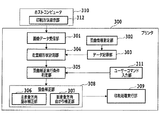
はじめに、本発明を適用可能な画像処理システムについて図3を用いて説明する。
図3は、本発明の一実施形態の画像形成装置を含む画像処理システムの全体構成を示すブロック図である。本実施形態では、画像形成装置として、プリンタ(特にレーザービームプリンタ)の例を示すが、画像形成装置は、インクジェットプリンタでも複合機でも何でもよい。
[First Embodiment]
First, an image processing system to which the present invention can be applied will be described with reference to FIG.
FIG. 3 is a block diagram showing the overall configuration of an image processing system including an image forming apparatus according to an embodiment of the present invention. In this embodiment, an example of a printer (particularly a laser beam printer) is shown as the image forming apparatus, but the image forming apparatus may be an ink jet printer or a multifunction machine.
また、以下の本実施形態では、1つの画像形成装置内に本発明を実現するための手段を全て備えている場合を示す。しかし、もちろん本発明を実現するための手段を1つの画像形成装置が備えている必要はなく、例えば、ホストコンピュータ(PC)上のプリンタドライバとしてその手段の一部を備えるようにしてもよい。 In the following embodiment, a case where all the means for realizing the present invention are provided in one image forming apparatus will be described. However, of course, it is not necessary for one image forming apparatus to have means for realizing the present invention. For example, a part of the means may be provided as a printer driver on a host computer (PC).
図3において、310はホストコンピュータであり、このホストコンピュータ310上のアプリケーションなどから印刷を行うとき、プリンタドライバ(不図示)によって作成された画像データがプリンタ300に送信される。
In FIG. 3,
301は画像データ受信部であり、ホストコンピュータ310が送信した画像データをプリンタ300において受信する。
An image
302は歪曲情報測定部であり、ここでは光ビームの曲がりなどを光学的に補正しないことによって生じる主走査方向の歪みと主走査方向と直交する副走査方向の曲がり及び傾きを測定し、これらの測定結果を歪曲情報として取得する。ただし、上記歪曲情報が同一機体で不変である場合には、一度、303のデータ記録部に歪曲情報を保存すれば、その後は本測定部にて測定を行わないようにしてもよい。
303はデータ記録部であり、ハードディスクやNVRAMなどで構成され、302の歪曲情報測定部で測定された歪曲情報などのデータを記録しておく。
A
304は走査線形状計測部であり、302の歪曲情報測定部において測定された走査線の副走査方向の曲がり情報(曲がりや傾きの大きさ)から、走査線全体の走査線形状を求めることができる。
305は歪曲補正実行条件判定部であり、画像を印字する際に主走査方向、副走査方向に対する補正のそれぞれについて補正を行うか否かを判定する。判定の条件としては、画像がモノカラーであるか否かや、主走査方向の歪み・副走査方向の曲がりや傾きの大きさや、ユーザーから補正処理についての指示入力があったかどうか、などがある。
306の主走査方向歪み補正部(第2の補正手段)は、主走査方向に対して生じた画像の歪みを補正する。主走査方向の画像の歪みとその補正の処理の詳細については後述する。 A main scanning direction distortion correction unit (second correction unit) 306 corrects image distortion generated in the main scanning direction. Details of image distortion in the main scanning direction and correction processing will be described later.
307の副走査方向曲がり補正部(第1の補正手段)は、304の走査線形状計測部で計測した走査線の形状を相殺するような曲がりと傾きを持った曲線を求め、その曲線の形状を画像データに反映させる。この反映を行うことで、普通に出力すると湾曲してしまう直線を湾曲せずに直線らしく表示することができるようになる。この処理の詳細については後述する。
A sub-scanning direction curve correction unit (first correction unit) 307 obtains a curve having a curve and an inclination that cancels the shape of the scanning line measured by the scanning line
308は歪曲補正部であり、306の主走査方向歪み補正部と307の副走査方向曲がり補正部とからなる。308の歪曲補正部では、305の歪曲補正実行条件判定部での判定にしたがって、主走査方向の歪み補正と副走査方向の曲がり補正を行う。
A
309は印刷処理実行部であり、308の歪曲補正部で補正が行われた画像データの印刷処理を行う。
311はプリンタ上のユーザーコマンド入力部であり、303のデータ記録部などに格納されている画像データの印刷を行う場合などに、ユーザーは308の歪曲量補正部での補正処理についてどのように行いたいかの指示または指定を行うことができる。
312はホストコンピュータ310上の印刷方法指示部であり、ホストコンピュータ310上のアプリケーションなどを通して印刷を行う場合、ユーザーは印刷のレイアウトなどと同様に308の歪曲補正部での補正処理についても設定を行うことが可能である。なお、312の印刷方法指示部は、プリンタドライバ(不図示)の一機能として実施してもよいし、それ以外のアプリケーションとして実施してもよい。
図4はレーザービームプリンタの概略構造を示した断面図である。ただし、図4の断面図ではドラムは1つしか描かれていないが、本発明では図1に示したように4ドラム型を想定している。 FIG. 4 is a sectional view showing a schematic structure of the laser beam printer. However, in the cross-sectional view of FIG. 4, only one drum is depicted, but the present invention assumes a four-drum type as shown in FIG.
図4においては、401は記録媒体である用紙、402は用紙401を保持する用紙カセットである。403はカセット給紙クラッチであり、用紙カセット402上に置かれた用紙401の最上位の用紙1枚のみを分離する。この給紙クラッチ403は、カム形状を有し、不図示の駆動手段によって給紙の度に回転することにより、この分離に伴い用紙の先端部を給紙ローラ404の位置まで搬送するものであり、1回転に対応して1枚の用紙を給紙する。給紙ローラ404は、用紙が給紙クラッチ403によって搬送されてくると、用紙401を軽く押圧しながら回転し、用紙401を搬送する。
In FIG. 4, 401 is a sheet as a recording medium, and 402 is a sheet cassette for holding the
一方、422は用紙台、421は手差し給紙クラッチであり、これら構成により、上述した用紙カセット402からの給紙だけでなく、給紙台422から1枚ずつ手差し給紙することを可能にする。
On the other hand,
405は転写ドラム、406は用紙の先端を挟み込むグリッパ、407は搬送ローラである。印刷時には、転写ドラム405は所定の速度で回転しており、その回転により転写ドラム405上のグリッパ406が用紙先端位置に来ると、グリッパは用紙先端部を挟み込む。このことと用紙搬送ローラ407の回転によって、用紙401は転写ドラム405に巻きつけられてさらに搬送される。
408は感光ドラム、409は現像器支持部、410はイエロー(Y)、トナー現像器、411はマゼンダ(M)トナー現像器、412はシアン(C)トナー現像器、413はブラック(BK)トナー現像器である。現像器指示部409は回転し、これにより所望の色トナーの現像器を、感光ドラム408に対し現像できる位置に搬送する。
414はレーザドライバである。レーザドライバ414は、不図示の印刷制御部から送出される描画用のドットデータに応じて不図示の半導体レーザのオン/オフを行ないながら感光ドラム408上を主走査線方向に走査して主走査ライン上に潜像を形成する。
408 is a photosensitive drum, 409 is a developing device support, 410 is a yellow (Y) toner developing device, 411 is a magenta (M) toner developing device, 412 is a cyan (C) toner developing device, and 413 is a black (BK) toner. It is a developing device. The developing
感光ドラム408はこの潜像形成と転写ドラム405上の用紙401の位置との同期がとれるよう回転駆動される。すなわち、不図示の帯電器により帯電された感光ドラム408の表面は上述のレーザービームの露光によって1ページ分の潜像が形成される。この感光ドラム408条の潜像は、現像器410、411、412、413の中の所定の色トナーの現像器によってトナー像として現像された後、転写ドラム405上の用紙401に上記トナー像が転写される。
The
さらに、必要な色トナーの下図だけ上述と同様の動作によって、転写ドラム405上の用紙401にトナー像が重ねられる。必要なトナー象が転写された用紙401は、転写分離つめ416によって転写ドラム405から分離される。そして、一対の定着ローラ417、417’によってトナー像が加熱定着され、搬送ローラ418、418’、および419を経て排紙トレイ420に排紙される。
Further, the toner image is superimposed on the
423は濃度センサであり、所定のタイミングで感光ドラム408上に形成されるYMCKそれぞれのパッチのトナー像の濃度を検知する。
A
画像形成装置全体の制御を行なうコントローラ(不図示)が、図4のレーザービームプリンタには備え付けられており、図3の301から309の各部の処理を行なう。
A controller (not shown) for controlling the entire image forming apparatus is provided in the laser beam printer of FIG. 4, and performs the processing of each
[動作の詳細]
続いて、図5を用いて本実施形態の画像形成装置の動作を詳細に説明する。
[Details of operation]
Next, the operation of the image forming apparatus of this embodiment will be described in detail with reference to FIG.
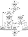
図5は、本実施形態の画像形成装置の動作を示すフローチャートである。 FIG. 5 is a flowchart showing the operation of the image forming apparatus of this embodiment.
ユーザーが画像の印刷を実行した場合、歪曲補正実行条件判定部(図3の305)において、入力画像データのカラー判定を行う(S501)。 When the user prints an image, the distortion correction execution condition determination unit (305 in FIG. 3) determines the color of the input image data (S501).
判定の結果(S502)、入力画像がモノカラーであると判定された場合、歪曲補正実行条件判定部では、歪曲補正処理に関するUIからの歪曲補正処理に関する指示がないかを確認する(S503)。ここで、UIとはユーザーコマンド入力部(図3の311)、あるいは印刷方法指示部(図3の312)のいずれでもよい。 As a result of the determination (S502), when it is determined that the input image is monochromatic, the distortion correction execution condition determination unit confirms whether there is an instruction regarding distortion correction processing from the UI regarding distortion correction processing (S503). Here, the UI may be either a user command input unit (311 in FIG. 3) or a printing method instruction unit (312 in FIG. 3).
また、UIは図6の(a)のように、補正の処理の内容を具体的に明示したものでもよいし、(b)のように処理内容は明示せずに内部的には対応する動作をするようにしてもよい。また、処理実行の指示方法も図6ではチェックボックスの例を示したが、チェックボックスに限らず、コマンド入力など何でもよい。 Further, the UI may be one in which the details of the correction processing are specifically shown as shown in FIG. 6A, or the corresponding operation is not shown in the inside as shown in FIG. 6B. You may make it do. In addition, the processing execution instruction method is shown as an example of a check box in FIG. 6, but is not limited to a check box and may be anything such as command input.
UIから副走査方向の曲がり補正処理を行うように指示があった場合、歪曲補正部(図3の308)において主走査方向と副走査方向の両方の補正処理を行う(S504)。 When there is an instruction from the UI to perform the bending correction process in the sub-scanning direction, the distortion correction unit (308 in FIG. 3) performs correction processes in both the main scanning direction and the sub-scanning direction (S504).
ここで、歪曲補正部に含まれる、主走査方向歪み補正部(図3の306)と副走査方向曲がり補正部(図3の307)による補正処理の詳細を含めて説明する。 Here, the details of the correction processing by the main scanning direction distortion correction unit (306 in FIG. 3) and the sub-scanning direction bending correction unit (307 in FIG. 3) included in the distortion correction unit will be described.
(主走査方向の歪み補正処理)
まず、主走査方向の歪みについて説明する。
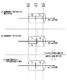
複数の光ビームの走査を光学的に制御しているプリンタにおいては、レンズの位置や傾きを変化させることによって光路差などの調節を行っている。このような調節を行っていると、図7の(a)に示すように光ビームの走査速度は一定であり、例えばドラム中心の左側と右側とでは走査時間はT0と同一である。しかし、複数の光ビームの走査を光学的に制御していない場合、図7の(b)に示すように走査速度は一定ではなくなる(不均一性)。このため、ドラム中心の左側と右側とでは異なり、走査時間も左側と右側でそれぞれT1、T2(本例ではT1<T2)というように異なってしまう。この結果、(a)ではちょうどドラム中心に描画されていた線分が(b)ではドラム中心より右にずれた位置に描画されてしまう。これは言い換えると、ドラム中心の左側の画像が伸び、右側の画像が縮んだことを表している。この状態を主走査方向の歪みと呼ぶことにする。
(Distortion correction processing in the main scanning direction)
First, distortion in the main scanning direction will be described.
In a printer that optically controls scanning of a plurality of light beams, the optical path difference and the like are adjusted by changing the position and tilt of a lens. When such adjustment is performed, the scanning speed of the light beam is constant as shown in FIG. 7A. For example, the scanning time is the same as T0 on the left and right sides of the drum center. However, when the scanning of a plurality of light beams is not optically controlled, the scanning speed is not constant as shown in FIG. 7B (non-uniformity). For this reason, the left and right sides of the drum center are different, and the scanning time is also different between the left side and the right side as T1 and T2 (T1 <T2 in this example). As a result, the line segment drawn at the center of the drum in (a) is drawn at a position shifted to the right from the center of the drum in (b). In other words, this represents that the image on the left side of the drum center is expanded and the image on the right side is contracted. This state is called distortion in the main scanning direction.
主走査方向歪み補正部では、図7の(c)に示すように画像が伸びた左側から1画素未満の単位の画素片を抜き取り、画像が縮んだ右側に挿入することで画像の伸び縮みを調整し、歪み補正を行う。ところで、一般に主走査方向の歪みは、ドラムの端では小さく、ドラム中心で最も大きくなる(つまり、ドラム中心に近い画素ほどより伸びたり縮んだりする)。そのため、一定の間隔で挿抜を行うと印字結果が元画像と異なって見えてしまう。 In the main scanning direction distortion correction unit, as shown in FIG. 7C, a pixel piece of a unit of less than one pixel is extracted from the left side where the image is stretched, and is inserted into the right side where the image is shrunk to reduce the expansion and contraction of the image. Adjust and correct distortion. By the way, generally, the distortion in the main scanning direction is small at the end of the drum and is largest at the center of the drum (that is, the pixels closer to the center of the drum extend or contract more). For this reason, if the insertion / extraction is performed at a constant interval, the print result looks different from the original image.
そこで、例えば画像の左半分と右半分を同数の領域に分割し、ドラムの中心(あるいは端)からの距離に応じて画素片の挿抜数に重み付けをするようにする。このように重み付けをして画素片の挿抜をする際に、ドラムの端に近い領域では画素片の挿抜数を少なくし、ドラム中心に近い領域では画素片の挿抜数を多くすることができ、適切な歪み補正を行うことができる。 Therefore, for example, the left half and the right half of the image are divided into the same number of regions, and the number of inserted / extracted pixel pieces is weighted according to the distance from the center (or end) of the drum. When weighting in this way and inserting and removing pixel pieces, the number of pixel pieces can be reduced in the region near the end of the drum, and the number of pixel pieces can be increased in the region near the drum center, Appropriate distortion correction can be performed.
なお、図7ではデータ記録部(図3の303)に保存された歪曲情報の歪みに関する情報を走査時間であるとして説明した。しかし、歪みに関する情報は走査時間でなくても実際にどれだけ歪んでいるかを示す他の情報例えば画素数でも距離でもよい。 In FIG. 7, the information related to the distortion of the distortion information stored in the data recording unit (303 in FIG. 3) is described as the scanning time. However, the information regarding the distortion may be other information indicating how much the distortion actually occurs, for example, the number of pixels or the distance, even if it is not the scanning time.
(副走査方向の曲がり補正処理)
次に副走査方向の曲がり補正部による曲がり補正処理について説明する。
光ビームの曲がりや傾きを光学的に制御して補正を行わない場合、エンジン(走査露光装置)に装着されているスキャナに依存するが、副走査方向に曲がった画像が出力されてしまう。この曲がりを補正するために、曲がる方向と逆方向にこの曲がりを相殺するようにあらかじめ画像を変換しておく。そのためには各色がどれくらい曲がっているのかという情報が必要となるため、補正を行う前に歪曲情報測定部(図3の302)で曲がりや傾きを測定し曲がり情報としてデータ記録部(図3の303)に保存しておく。
(Bend correction processing in the sub-scanning direction)
Next, bending correction processing by the bending correction unit in the sub-scanning direction will be described.
When correction is not performed by optically controlling the bending and tilting of the light beam, an image bent in the sub-scanning direction is output, depending on the scanner mounted on the engine (scanning exposure apparatus). In order to correct this bend, the image is converted in advance so as to cancel this bend in the direction opposite to the bend direction. For this purpose, information about how much each color is bent is necessary. Therefore, before correction, the distortion information measuring unit (302 in FIG. 3) measures the bend and inclination, and the data recording unit (FIG. 3) is used as the bending information. 303).
データ記録部に格納されている歪曲情報に含まれる曲がり情報から走査線形状計測部(図3の304)で各走査線の形状を求める。曲がった走査線の形状は走査線上の画素のうち3画素以上において、走査線の理想位置からのずれ量(理想の走査線は直線となるので、その直線からの距離と言い換えることもできる)を求めることで算出できる。このずれ量は既定のパッチを印字すると、どの色がどの位置に印字される、という基準位置との差で表される。実際に、既定のパッチを印字したときに印字したパッチが基準位置からどれくらいずれているかを測定することでずれ量を求めることができる。走査線上の3画素において走査線の理想位置からどれくらいずれているかがわかれば、そのずれた3点を結ぶことで走査線の形状がわかり、その3点の座標から走査線の描く曲線(直線)の式を求めることも可能である。 The shape of each scanning line is obtained by the scanning line shape measuring unit (304 in FIG. 3) from the bending information included in the distortion information stored in the data recording unit. The shape of the curved scanning line is a deviation amount from the ideal position of the scanning line in three or more pixels on the scanning line (the ideal scanning line is a straight line, and can be rephrased as a distance from the straight line). It can be calculated by obtaining. The amount of deviation is represented by the difference from the reference position, which color is printed at which position when a predetermined patch is printed. Actually, the deviation amount can be obtained by measuring how much the printed patch is from the reference position when the predetermined patch is printed. If the three pixels on the scanning line indicate how far from the ideal position of the scanning line, the shape of the scanning line can be determined by connecting the three shifted points, and the curve (straight line) drawn by the scanning line from the coordinates of the three points. It is also possible to obtain the following equation.
走査線の形状を求めたら、走査線が図8の(a)の点線のような曲線になっていることがわかったとする。このとき、その湾曲した走査線を理想の走査線に対して線対称となるような曲線(図8(a)の実線)を求める。この求めた曲線(以下、走査線湾曲相殺曲線と呼ぶ)を同じプリンタで印刷すれば、曲がりや傾きが相殺され、本来描きたい直線を描くことができる。そこで、画像データ全体を走査線湾曲相殺曲線で曲がりを相殺するように変換を行う。 When the shape of the scanning line is obtained, it is assumed that the scanning line is a curve like the dotted line in FIG. At this time, a curved line (solid line in FIG. 8A) is obtained such that the curved scanning line is symmetric with respect to the ideal scanning line. If the obtained curve (hereinafter referred to as a scanning line curve canceling curve) is printed by the same printer, the bend and the inclination are canceled, and a straight line originally desired can be drawn. Therefore, the entire image data is converted so as to cancel the bending by the scanning line curve cancellation curve.
しかし、画像データは画素単位にサンプリングされているため、走査線湾曲相殺曲線の形状をそのまま変換に反映させることはできない。そこで、本来、同一ライン上に存在する画像データをあるポイントで1ライン分上げたり下げたりすることで曲線を表す。図8の(a)の実線に対してこの近似を行った結果が図8の(b)の実線である。ここで、同一ライン上に存在する画像データをあるポイントで1ライン分上げたり下げたりすることを「乗り換え」と呼び、「乗り換え」を行うポイントを「乗り換えポイント」と呼ぶことにする。 However, since the image data is sampled in units of pixels, the shape of the scanning line curve cancellation curve cannot be directly reflected in the conversion. Therefore, a curve is represented by raising or lowering image data originally existing on the same line by one line at a certain point. The result of this approximation for the solid line in FIG. 8A is the solid line in FIG. Here, raising or lowering image data existing on the same line by one line at a certain point is referred to as “transfer”, and a point at which “transfer” is performed is referred to as “transfer point”.
この乗り換えを利用することで、走査線湾曲相殺曲線の形状をほぼ画像データに反映させることが可能となる。ちなみに、図8の(b)では曲線の副走査方向の値(以下、Y座標(同図の上下方向の座標)の値とする。単位はラインである)が、例えば0以上1未満のときは0、1以上2未満のときは1(ライン)というような近似を行っている。つまり、同図の例では、走査線湾曲相殺曲線上でY=1からY=2となる点を乗り換えポイントとしている。 By utilizing this transfer, the shape of the scanning line curve cancellation curve can be substantially reflected in the image data. Incidentally, in FIG. 8B, when the value in the sub-scanning direction of the curve (hereinafter referred to as the value of the Y coordinate (the vertical coordinate in the figure), the unit is a line) is 0 or more and less than 1, for example. Is an approximation such that 0 (zero), 1 or more and less than 2 is 1 (line). That is, in the example shown in the figure, the point where Y = 1 to Y = 2 on the scanning line curve cancellation curve is used as a transfer point.
ここで、乗り換えポイント(言い換えると、直線を分割して1ライン分上げたり下げたりする点)は一意に定まるわけではなく、別の乗り換えポイントを設定することで、異なる近似を行うことができる。 Here, a transfer point (in other words, a point where a straight line is divided and raised or lowered by one line) is not uniquely determined, and different approximation can be performed by setting another transfer point.
しかし、このような乗り換えを行うだけでは、直線のようなオブジェクトでは乗り換えポイントで段差が目立ってしまうため、実際は段差の前後で補間処理を行い、段差が目立たなくなるようしている。一方、低濃度の領域では、例えば、図2の(a)の楕円で囲まれていない部分のような特定のパターンを繰り返すことで低濃度を表現する。しかし、図2の(a)の楕円で囲まれている部分のように補間を行うことによって濃度を表現するためのパターンが崩れてしまい、ラインの太さが変化するため補間実行部分の濃度が変わって見えてしまう。このように乗り換えポイントの前後で濃度段差が起きるなどの問題が生じることがあるので低濃度領域では補間処理を行わないようにする。 However, if only such a change is made, a step becomes conspicuous at a change point in an object such as a straight line. Therefore, interpolation processing is actually performed before and after the step so that the step becomes inconspicuous. On the other hand, in the low density region, for example, a low density is expressed by repeating a specific pattern such as a part not surrounded by an ellipse in FIG. However, the pattern for expressing the density collapses by performing the interpolation as in the part surrounded by the ellipse in FIG. 2A, and the line thickness changes. It looks different. In this way, problems such as a density step occurring before and after the transfer point may occur. Therefore, the interpolation process is not performed in the low density region.
一方、ここで図5に戻り、S503において、UIから副走査方向の補正処理を行うように指示がなかった場合、副走査方向の補正を行わずに印刷を行う。このように副走査の補正を行わないようにすることで、課題となっている図2(a)(b)に示すような補間処理、補間のON/OFF判定、起因する画像不良が発生しないようにすることができる。さらに乗り換えも行わないため、図2(c)に示すような乗り換えに起因するスジなどの画像不良も発生しないようにすることができる。 On the other hand, referring back to FIG. 5, if there is no instruction from the UI to perform correction processing in the sub-scanning direction in S503, printing is performed without correction in the sub-scanning direction. By not performing the sub-scan correction in this way, the interpolation processing as shown in FIGS. 2A and 2B, the ON / OFF determination of interpolation, and the resulting image defect do not occur. Can be. Further, since no transfer is performed, image defects such as streaks due to the transfer as shown in FIG. 2C can be prevented.
ここで、副走査方向の補正処理を行わないことで、走査線が曲がったままになってしまうが、モノカラー画像の場合は走査線の曲がりが目立ちにくいため、図2に示すような、より目立つ画像不良が起こらないようにすることを優先するようにする。 If the correction process in the sub-scanning direction is not performed, the scanning line remains bent. However, in the case of a monochromatic image, the bending of the scanning line is not conspicuous, and as shown in FIG. Give priority to avoiding noticeable image defects.
S505では、入力画像データが1色のカラー画像であった場合、入力画像の1色に対応する、エンジン(走査露光装置)に装着されているスキャナについての歪曲情報をデータ記録部から取得する。データの取得後、歪曲補正実行条件判定部では、歪曲情報を基に主走査方向の歪みが基準値未満かどうかを判定する(S506)。判定の結果、主走査方向の歪みが基準値未満であれば、主走査方向と副走査方向の両方の補正処理を行わないようにする(S507)。それに対し、主走査方向の歪みが基準値以上であれば、主走査方向の歪み補正のみ行う(S510)。 In step S505, if the input image data is a single color image, distortion information about the scanner mounted on the engine (scanning exposure apparatus) corresponding to one color of the input image is acquired from the data recording unit. After acquiring the data, the distortion correction execution condition determining unit determines whether the distortion in the main scanning direction is less than the reference value based on the distortion information (S506). If the distortion in the main scanning direction is less than the reference value as a result of the determination, correction processing in both the main scanning direction and the sub-scanning direction is not performed (S507). On the other hand, if the distortion in the main scanning direction is equal to or greater than the reference value, only distortion correction in the main scanning direction is performed (S510).
一方、入力画像データが2色以上使用しているカラー画像であった場合、全色の、エンジンに装着されているスキャナの歪曲情報をデータ記録部から取得し(S508)、副走査方向の曲がり情報が基準値未満かどうかを判定する(S509)。判定の結果、副走査方向の曲がりや傾きの大きさが基準値未満であれば、副走査方向の補正は行わず、主走査方向の歪み補正処理のみ行う(S510)。それに対し、副走査方向の曲がりが基準値以上であれば、従来通り主走査方向と副走査方向の両方の補正処理を実行する。 On the other hand, if the input image data is a color image using two or more colors, the distortion information of the scanner mounted on the engine for all colors is acquired from the data recording unit (S508), and the bending in the sub-scanning direction is obtained. It is determined whether the information is less than the reference value (S509). If the result of determination is that the degree of bending or tilting in the sub-scanning direction is less than the reference value, correction in the sub-scanning direction is not performed and only distortion correction processing in the main scanning direction is performed (S510). On the other hand, if the bending in the sub-scanning direction is equal to or greater than the reference value, correction processing in both the main scanning direction and the sub-scanning direction is executed as usual.
[第2の実施形態]
第2の実施形態としては、1つの画像形成装置内に本発明を実現するための手段を全て備えていない場合を示す。例えば、ホストベースのプリンタに対して本発明を適用した場合である。ホストベースのプリンタでは、モノカラーか否かの判定(カラー/モノクロ判定でもよい)、副走査方向の曲がりを補正するための画像データ変換などをホスト(PC)で行うことが想定される。
[Second Embodiment]
As a second embodiment, a case where not all the means for realizing the present invention are provided in one image forming apparatus will be described. For example, the present invention is applied to a host-based printer. In a host-based printer, it is assumed that the host (PC) performs determination as to whether or not the image is monochrome (color / monochrome determination), image data conversion for correcting bending in the sub-scanning direction, and the like.
そのため、UIからの歪曲補正処理実行の指示は312の印刷方法指示部を通して行われる。また、図3の301、304、305がホスト側にあることになり、302の歪曲量測定部で測定された歪曲情報をコントローラとホストの両方に通知する必要がある。歪曲情報を通知されたホストは、第1の実施形態で述べたのと同様の手法で図5のS503、S505、S506(カラー画像の場合はS508、S509)の判定を行う。
For this reason, an instruction to execute distortion correction processing from the UI is given through a printing
ホスト側で歪曲補正実行条件を判定した結果、副走査方向の曲がり補正が必要であると判定されたら、ホストで画像データの変換を行い、変換された画像データをプリンタのコントローラに送信する。同時に主走査方向の歪み補正が必要かどうかもコントローラに通知する。コントローラは主走査方向の歪み補正が必要である場合は、同補正を行い、印刷を実行する。このようにすれば、1つの画像形成装置内に本発明を実現するための手段を全て備えている場合と同様の効果が得られる。 As a result of determining the distortion correction execution condition on the host side, if it is determined that the bending correction in the sub-scanning direction is necessary, the host converts the image data, and transmits the converted image data to the printer controller. At the same time, it notifies the controller whether or not distortion correction in the main scanning direction is necessary. When the distortion correction in the main scanning direction is necessary, the controller performs the correction and executes printing. In this way, the same effect as when all the means for realizing the present invention are provided in one image forming apparatus can be obtained.
なお、上述した実施形態はあくまで一例であって、他の構成で実現してもよい。 The above-described embodiment is merely an example, and may be realized with other configurations.
[第3の実施形態]
第1の実施形態では、図5のS506で、主走査方向の歪みの大きさを確認し、主走査方向の補正処理を行うか否かを判定しているが、ここで主走査方向の歪みの大きさの確認を行わずに、主走査方向の補正処理は必ず行うようにしてもよい。
[Third Embodiment]
In the first embodiment, in S506 in FIG. 5, the magnitude of distortion in the main scanning direction is confirmed and it is determined whether or not correction processing in the main scanning direction is performed. Here, distortion in the main scanning direction is determined. The correction process in the main scanning direction may always be performed without confirming the size of.
同様に、図5のS509で全色のエンジン(走査露光装置)に装着されているスキャナの曲がりや傾きの大きさを確認し、副走査方向の補正処理を行うか否かを判定している。本実施形態では、これに限らず、ここで副走査方向の曲がりや傾きの大きさの確認を行わずに、副走査方向の補正処理は必ず行うようにしてもよい。 Similarly, in step S509 in FIG. 5, the degree of bending or tilt of the scanner mounted on the all-color engine (scanning exposure apparatus) is confirmed, and it is determined whether or not correction processing in the sub-scanning direction is performed. . In the present embodiment, the present invention is not limited to this, and correction processing in the sub-scanning direction may always be performed without confirming the magnitude of the bending or inclination in the sub-scanning direction.
また、図5のS509で全色のエンジンに装着されているスキャナの主走査方向の歪みの大きさについても確認し、全色のエンジンに装着されているスキャナの主走査方向の歪みが基準値未満であれば、主走査方向の補正処理を行わないようにしてもよい。 Further, in S509 in FIG. 5, the magnitude of distortion in the main scanning direction of the scanner mounted on the all-color engine is also confirmed, and the distortion in the main scanning direction of the scanner mounted on the all-color engine is the reference value. If it is less, correction processing in the main scanning direction may not be performed.
つまり、全色のエンジンに装着されているスキャナの副走査方向の曲がりや傾きの大きさ、及び/または主走査方向の歪みの大きさによって、副走査方向および主走査方向の補正処理を行うか否かが変更できるようなシステムを構築してもよい。 In other words, whether correction processing in the sub-scanning direction and the main scanning direction is performed according to the degree of bending or tilting in the sub-scanning direction and / or the magnitude of distortion in the main scanning direction of the scanners mounted on all color engines. You may build the system which can change whether or not.
[第4の実施形態]
第1の実施形態では、図5のS503での歪曲補正処理実行のUIの例として図6のように副走査方向の曲がり補正について実行するか否かを選択するコマンドを挙げたが、この限りではない。例えば、図3の311、312といったUI部から主走査方向の歪み補正処理を実行するかどうかについて、主走査方向について単独で指示できるようにしてもよい。あるいは、主走査方向と副走査方向の両方について同時に補正処理を実行するか否かを指示できるようにしてもよい。
[Fourth Embodiment]
In the first embodiment, as an example of the UI for executing the distortion correction processing in S503 in FIG. 5, a command for selecting whether or not to execute the bending correction in the sub-scanning direction as shown in FIG. is not. For example, the main scanning direction alone may be instructed as to whether or not to execute distortion correction processing in the main scanning direction from the
つまり、UI部から主走査方向と副走査方向のそれぞれについて補正を行うかどうかの指示を行うことができ、UI部からの入力に応じてその通りに(指示を優先して)動作するようなシステムを構築してもよい。 That is, it is possible to instruct whether to perform correction in each of the main scanning direction and the sub-scanning direction from the UI unit, and to operate according to the input from the UI unit (prioritizing the instruction). A system may be constructed.
[その他の実施形態]
また、本発明の目的は、上述した実施形態で示したフローチャートの手順を実現するプログラムコードを記憶した記憶媒体から、システムあるいは装置のコンピュータ(またはCPUやMPU)がそのプログラムコードを読出し実行することによっても達成される。
この場合、記憶媒体から読み出されたプログラムコード自体が、コンピュータに、上述した実施形態の機能を実現させることになる。そのため、このプログラムコード及びプログラムコードを記憶/記録したコンピュータ読み取り可能な記憶媒体も本発明の一つを構成することになる。
[Other Embodiments]
Another object of the present invention is that a computer (or CPU or MPU) of a system or apparatus reads and executes the program code from a storage medium that stores the program code for realizing the procedure of the flowchart shown in the above-described embodiment. Is also achieved.
In this case, the program code itself read from the storage medium causes the computer to realize the functions of the above-described embodiments. Therefore, this program code and a computer-readable storage medium storing / recording the program code also constitute one aspect of the present invention.
プログラムコードを供給するための記憶媒体としては、例えば、フロッピー(登録商標)ディスク、ハードディスク、光ディスク、光磁気ディスク、CD−ROM、CD−R、磁気テープ、不揮発性のメモリカード、ROMなどを用いることができる。 As a storage medium for supplying the program code, for example, a floppy (registered trademark) disk, hard disk, optical disk, magneto-optical disk, CD-ROM, CD-R, magnetic tape, nonvolatile memory card, ROM, or the like is used. be able to.
また、前述した実施形態の機能は、コンピュータが、読み出したプログラムを実行することによって実現される。また、このプログラムの実行とは、そのプログラムの指示に基づき、コンピュータ上で稼動しているOSなどが、実際の処理の一部または全部を行う場合も含まれる。 The functions of the above-described embodiments are realized by a computer executing a read program. The execution of the program includes a case where an OS or the like running on the computer performs part or all of the actual processing based on an instruction of the program.
さらに、前述した実施形態の機能は、コンピュータに挿入された機能拡張ボードやコンピュータに接続された機能拡張ユニットによっても実現することもできる。この場合、まず、記憶媒体から読み出されたプログラムが、コンピュータに挿入された機能拡張ボードやコンピュータに接続された機能拡張ユニットに備わるメモリに書き込まれる。その後、そのプログラムの指示に基づき、その機能拡張ボードや機能拡張ユニットに備わるCPUなどが実際の処理の一部または全部を行う。こうした機能拡張ボードや機能拡張ユニットによる処理によっても前述した実施形態の機能が実現される。 Furthermore, the functions of the above-described embodiments can also be realized by a function expansion board inserted into a computer or a function expansion unit connected to a computer. In this case, first, the program read from the storage medium is written in a memory provided in a function expansion board inserted into the computer or a function expansion unit connected to the computer. Thereafter, based on the instructions of the program, the CPU or the like provided in the function expansion board or function expansion unit performs part or all of the actual processing. The functions of the above-described embodiment are also realized by processing by such a function expansion board or function expansion unit.
以上、いくつかの実施の形態について述べてきたが、本発明は上記実施形態に限定されるものではなく、本発明の趣旨に基づき種々の変形(各実施形態の有機的な組合せを含む)が可能であり、それらを本発明の範囲から排除するものではない。また、本発明の様々な例と実施形態を示して説明したが、当業者であれば、本発明の趣旨と範囲は、本明細書内の特定の説明に限定されるものではない。 As mentioned above, although several embodiment was described, this invention is not limited to the said embodiment, Based on the meaning of this invention, various deformation | transformation (The organic combination of each embodiment is included.) And are not excluded from the scope of the present invention. Further, although various examples and embodiments of the present invention have been shown and described, those skilled in the art will not limit the spirit and scope of the present invention to the specific description in the present specification.
301 画像データ受信部
302 歪曲情報測定部
303 データ記録部
304 走査線形状計測部
305 歪曲補正実行条件判定部
306 主走査方向歪み補正部
307 副走査方向曲がり補正部
308 歪曲補正部
309 印刷処理実行部
310 ホストコンピュータ
311 ユーザーコマンド入力部
312 印刷方法指示部
DESCRIPTION OF
Claims (9)
前記光ビームを主走査方向に走査させた時の走査線の形状の曲がりや傾きを相殺するように画像データの変換を行うことで副走査方向の曲がりや傾きを補正する第1の補正手段と、
走査線の主走査方向の歪みを補正する第2の補正手段と、
入力された画像が2色以上のカラーで構成されている場合は、前記第1の補正手段と前記第2の補正手段による補正を両方とも実行し、入力された画像が1色のみで構成されている場合には、前記第2の補正手段による補正のみを実行する制御手段と
を有することを特徴とする画像形成装置。 In an image forming apparatus that scans each of a plurality of light beams in a main scanning direction and a sub-scanning direction orthogonal to the main scanning direction to form an image having a plurality of colors.
First correction means for correcting the bending or inclination in the sub-scanning direction by converting the image data so as to cancel the bending or inclination of the shape of the scanning line when the light beam is scanned in the main scanning direction; ,
Second correction means for correcting distortion in the main scanning direction of the scanning line;
When the input image is composed of two or more colors, both the first correction unit and the correction by the second correction unit are executed, and the input image is composed of only one color. An image forming apparatus comprising: a control unit that executes only the correction by the second correction unit.
前記印刷方法指示手段にて、前記第1の補正手段および前記第2の補正手段による補正のそれぞれについて、実行するか否かの指定があったかどうかを判定する補正実行条件判定手段とをさらに備え、
前記制御手段は、前記補正実行条件判定手段での判定に基づいて、前記第1の補正手段および前記第2の補正手段による補正の実行を制御することを特徴とする、請求項1に記載の画像形成装置。 A printing method instruction means capable of instructing whether or not to execute each of the corrections by the first correction means and the second correction means from the user;
A correction execution condition determination unit that determines whether or not the printing method instruction unit has specified whether to execute each of the corrections by the first correction unit and the second correction unit;
2. The control unit according to claim 1, wherein the control unit controls the execution of correction by the first correction unit and the second correction unit based on determination by the correction execution condition determination unit. Image forming apparatus.
前記補正実行条件判定手段は、さらに前記測定手段にて測定した各色のビームの曲がりや傾きが基準値未満かどうかと、前記測定手段にて測定した各色のビームの歪みが基準値未満かどうかとを判定し、
前記制御手段は、前記補正実行条件判定手段により、前記測定手段により測定した各色の光ビームの曲がりや傾きが基準値未満であると判定された場合に、前記第1の補正手段による補正を実行しないように制御し、前記測定手段にて測定した各色の光ビームの歪みが基準値未満であると判定された場合には、前記第2の補正手段による補正を実行しないように制御することを特徴とする請求項2に記載の画像形成装置。 When each of the plurality of light beams is scanned in the main scanning direction, the apparatus further includes a measuring unit that measures information about the bending, inclination, and distortion of each color light beam,
The correction execution condition determination unit further determines whether the bending or inclination of the beam of each color measured by the measurement unit is less than a reference value, and whether the distortion of the beam of each color measured by the measurement unit is less than a reference value. And
The control means executes correction by the first correction means when the correction execution condition determination means determines that the bending or inclination of the light beam of each color measured by the measurement means is less than a reference value. And when the distortion of the light beam of each color measured by the measuring unit is determined to be less than a reference value, control is performed so that the correction by the second correcting unit is not executed. The image forming apparatus according to claim 2.
前記光ビームを主走査方向に走査させた時の走査線の形状の曲がりや傾きを相殺するように画像データの変換を行うことで副走査方向の曲がりや傾きを補正する第1の補正工程と、
走査線の主走査方向の歪みを補正する第2の補正工程と、
入力された画像が2色以上のカラーで構成されている場合は、前記第1の補正工程と前記第2の補正工程による補正を両方とも実行し、入力された画像が1色のみで構成されている場合には、前記第2の補正工程による補正のみを実行する制御工程と
を有することを特徴とする画像形成方法。 An image forming method in an image forming apparatus that scans each of a plurality of light beams in a main scanning direction and a sub scanning direction orthogonal to the main scanning direction to form an image having a plurality of colors,
A first correction step of correcting the bending or inclination in the sub-scanning direction by converting image data so as to cancel the bending or inclination of the shape of the scanning line when the light beam is scanned in the main scanning direction; ,
A second correction step of correcting distortion in the main scanning direction of the scanning line;
If the input image is composed of two or more colors, both the first correction step and the correction by the second correction step are executed, and the input image is composed of only one color. A control step of performing only the correction by the second correction step.
前記印刷方法指示工程にて、前記第1の補正工程および前記第2の補正工程による補正のそれぞれについて、実行するか否かの指定があったかどうかを判定する補正実行条件判定工程とをさらに備え、
前記制御工程は、前記補正実行条件判定工程での判定に基づいて、前記第1の補正工程および前記第2の補正工程による補正の実行を制御することを特徴とする、請求項5に記載の画像形成方法。 A printing method instruction step capable of instructing whether or not to execute each of the corrections by the first correction step and the second correction step from the user;
A correction execution condition determination step for determining whether or not to execute each of the corrections in the first correction step and the second correction step in the printing method instruction step;
The said control process controls execution of correction | amendment by a said 1st correction process and a said 2nd correction process based on the determination in the said correction execution condition determination process, The said control process is characterized by the above-mentioned. Image forming method.
前記補正実行条件判定工程は、さらに前記測定工程にて測定した各色のビームの曲がりや傾きが基準値未満かどうかと、前記測定工程にて測定した各色のビームの歪みが基準値未満かどうかとを判定し、
前記制御工程は、前記補正実行条件判定工程により、前記測定工程により測定した各色の光ビームの曲がりや傾きが基準値未満であると判定された場合に、前記第1の補正工程による補正を実行しないように制御し、前記測定工程にて測定した各色の光ビームの歪みが基準値未満であると判定された場合には、前記第2の補正工程による補正を実行しないように制御することを特徴とする請求項6に記載の画像形成方法。 When each of the plurality of light beams is scanned in the main scanning direction, the method further includes a measurement step of measuring information on bending, inclination, and distortion of the light beams of the respective colors,
The correction execution condition determination step further includes whether or not the bending or inclination of the beam of each color measured in the measurement step is less than a reference value, and whether or not the distortion of the beam of each color measured in the measurement step is less than a reference value. And
The control step executes the correction by the first correction step when it is determined by the correction execution condition determination step that the bending or inclination of the light beam of each color measured by the measurement step is less than a reference value. And when the distortion of the light beam of each color measured in the measurement step is determined to be less than a reference value, control is performed so that the correction by the second correction step is not executed. The image forming method according to claim 6.
Priority Applications (5)
| Application Number | Priority Date | Filing Date | Title |
|---|---|---|---|
| JP2008271969A JP2010099885A (en) | 2008-10-22 | 2008-10-22 | Image forming device, image forming method, and image forming program |
| US12/571,896 US20100097623A1 (en) | 2008-10-22 | 2009-10-01 | Image forming apparatus, image forming method, and image forming program |
| US12/603,246 US20100103441A1 (en) | 2008-10-22 | 2009-10-21 | Image forming apparatus, image forming method, and image forming program |
| RU2009138978/08A RU2421815C1 (en) | 2008-10-22 | 2009-10-21 | Device to generate images and method of image generation |
| CN2009102043814A CN101727041B (en) | 2008-10-22 | 2009-10-22 | Image forming apparatus, and image forming method |
Applications Claiming Priority (1)
| Application Number | Priority Date | Filing Date | Title |
|---|---|---|---|
| JP2008271969A JP2010099885A (en) | 2008-10-22 | 2008-10-22 | Image forming device, image forming method, and image forming program |
Publications (2)
| Publication Number | Publication Date |
|---|---|
| JP2010099885A true JP2010099885A (en) | 2010-05-06 |
| JP2010099885A5 JP2010099885A5 (en) | 2011-12-08 |
Family
ID=42108404
Family Applications (1)
| Application Number | Title | Priority Date | Filing Date |
|---|---|---|---|
| JP2008271969A Pending JP2010099885A (en) | 2008-10-22 | 2008-10-22 | Image forming device, image forming method, and image forming program |
Country Status (4)
| Country | Link |
|---|---|
| US (2) | US20100097623A1 (en) |
| JP (1) | JP2010099885A (en) |
| CN (1) | CN101727041B (en) |
| RU (1) | RU2421815C1 (en) |
Cited By (2)
| Publication number | Priority date | Publication date | Assignee | Title |
|---|---|---|---|---|
| JP2013106261A (en) * | 2011-11-15 | 2013-05-30 | Canon Inc | Image processing apparatus, image processing method, and computer program |
| JP2016150579A (en) * | 2015-02-19 | 2016-08-22 | キヤノン株式会社 | Image forming device |
Families Citing this family (8)
| Publication number | Priority date | Publication date | Assignee | Title |
|---|---|---|---|---|
| JP2010099885A (en) * | 2008-10-22 | 2010-05-06 | Canon Inc | Image forming device, image forming method, and image forming program |
| JP5402976B2 (en) * | 2011-04-27 | 2014-01-29 | コニカミノルタ株式会社 | Image forming apparatus and gradation correction method |
| JP2014106422A (en) * | 2012-11-28 | 2014-06-09 | Ricoh Co Ltd | Image forming apparatus and image correction method |
| JP6128817B2 (en) * | 2012-11-30 | 2017-05-17 | キヤノン株式会社 | Image forming apparatus and image forming method |
| JP5598576B1 (en) * | 2013-06-24 | 2014-10-01 | 富士ゼロックス株式会社 | MFP and reader |
| JP6270597B2 (en) * | 2014-04-04 | 2018-01-31 | キヤノン株式会社 | Image forming apparatus |
| JP6371585B2 (en) * | 2014-05-22 | 2018-08-08 | キヤノン株式会社 | Image forming apparatus |
| CN105472340B (en) * | 2015-12-21 | 2018-08-17 | 常州信息职业技术学院 | A kind of image formation intelligent high definition video monitoring system corrected based on optics and electricity |
Citations (7)
| Publication number | Priority date | Publication date | Assignee | Title |
|---|---|---|---|---|
| JPH09240060A (en) * | 1996-03-04 | 1997-09-16 | Ricoh Co Ltd | Method and apparatus for forming image |
| JP2000155453A (en) * | 1998-11-20 | 2000-06-06 | Canon Inc | Device and method for forming image |
| JP2004262234A (en) * | 2003-02-10 | 2004-09-24 | Ricoh Co Ltd | Optical writing device, image formation device, optical writing correction method, computer program, and printing medium |
| JP2006003907A (en) * | 1993-12-29 | 2006-01-05 | Xerox Corp | Multiple-beam raster output scanner optical system having telecentric chief exit rays |
| JP2007121923A (en) * | 2005-10-31 | 2007-05-17 | Canon Inc | Image forming apparatus, control method therefor, and program |
| JP2007140570A (en) * | 1997-09-03 | 2007-06-07 | Fuji Xerox Co Ltd | Color image forming apparatus |
| JP2009294381A (en) * | 2008-06-04 | 2009-12-17 | Canon Inc | Image forming apparatus and image forming method |
Family Cites Families (53)
| Publication number | Priority date | Publication date | Assignee | Title |
|---|---|---|---|---|
| US3885244A (en) * | 1970-12-17 | 1975-05-20 | Hell Rudolf Dr Ing | Method of producing color correction signals and color separation signals |
| JP2849627B2 (en) * | 1989-02-27 | 1999-01-20 | 富士ゼロックス株式会社 | Image processing device |
| JPH04204461A (en) * | 1990-11-29 | 1992-07-24 | Minolta Camera Co Ltd | Controller for image density |
| US5589954A (en) * | 1993-05-28 | 1996-12-31 | Ricoh Company, Ltd. | γ-correction curve selecting apparatus and a γ-correction curve creating apparatus |
| JPH0829701A (en) * | 1994-07-18 | 1996-02-02 | Olympus Optical Co Ltd | Stereoscopic viewing endoscope system |
| US5715498A (en) * | 1994-09-16 | 1998-02-03 | Canon Kabushiki Kaisha | Color image forming apparatus and method for forming a color image corrected for aberration in registration of image stations for each color |
| US6571011B1 (en) * | 1995-06-06 | 2003-05-27 | Apple Computer, Inc. | Conversion of output device color values to minimize image quality artifacts |
| KR100240070B1 (en) * | 1997-07-10 | 2000-01-15 | Samsung Electronics Co Ltd | Apparatus and method for color calibration in image system |
| JPH11239250A (en) * | 1997-11-17 | 1999-08-31 | Ricoh Co Ltd | Digital composite device |
| JP3777785B2 (en) * | 1998-03-18 | 2006-05-24 | コニカミノルタビジネステクノロジーズ株式会社 | Image processing device |
| US6529643B1 (en) * | 1998-12-21 | 2003-03-04 | Xerox Corporation | System for electronic compensation of beam scan trajectory distortion |
| JP4074414B2 (en) * | 1999-02-10 | 2008-04-09 | セイコーエプソン株式会社 | Adjusting the recording position misalignment during bidirectional printing where the correction value is changed between monochrome printing and color printing |
| JP3740910B2 (en) * | 1999-09-29 | 2006-02-01 | コニカミノルタホールディングス株式会社 | Image processing method and image processing apparatus |
| JP4199893B2 (en) * | 1999-12-28 | 2008-12-24 | 株式会社リコー | Image forming apparatus |
| US6229555B1 (en) * | 2000-05-17 | 2001-05-08 | Lexmark International, Inc. | Method and apparatus for minimizing visual artifacts generated by an electrophotographic machine during imaging |
| JP2002048993A (en) * | 2000-05-25 | 2002-02-15 | Canon Inc | Optical scanner and image forming device using the same |
| US7898695B1 (en) * | 2000-10-06 | 2011-03-01 | Lexmark International, Inc. | Method of compensating for electronic printhead skew and bow correction in an imaging machine to reduce print artifacts |
| JP2002196560A (en) * | 2000-12-26 | 2002-07-12 | Konica Corp | Multicolor image forming device |
| JP2002247371A (en) * | 2001-02-21 | 2002-08-30 | Ricoh Co Ltd | Image processor and recording medium having recorded image processing program |
| US6791596B2 (en) * | 2001-06-28 | 2004-09-14 | Ricoh Company, Ltd. | Method and apparatus for image forming capable of effectively generating pixel clock pulses |
| US6657650B1 (en) * | 2002-07-23 | 2003-12-02 | Lexmark International, Inc. | Method of laser printhead registration control in an electrophotographic machine |
| US6933957B2 (en) * | 2002-09-24 | 2005-08-23 | Ricoh Company, Ltd. | Pixel clock generation apparatus, pixel clock generation method, and image forming apparatus capable of correcting main scan dot position shift with a high degree of accuracy |
| US20040128938A1 (en) * | 2002-12-26 | 2004-07-08 | Robert Cure | Wall structure with releasable canvas panels and aerodynamic canvas panel supporting braces |
| US7315320B2 (en) * | 2003-02-10 | 2008-01-01 | Ricoh Company, Ltd. | Optical writing system and method, and image forming apparatus receiving an external parameter |
| US7354123B2 (en) * | 2003-06-04 | 2008-04-08 | Seiko Epson Corporation | Printing method and printing apparatus |
| US7123282B2 (en) * | 2004-01-14 | 2006-10-17 | Lexmark International, Inc. | Method and apparatus for minimizing visual artifacts in images generated by an electrophotographic machine |
| JP2005216030A (en) * | 2004-01-30 | 2005-08-11 | Canon Inc | Information processor, data processing method, computer-readable storage medium storing program, and program |
| US7313352B2 (en) * | 2004-03-09 | 2007-12-25 | Ricoh Company, Ltd. | Image forming apparatus, method of controlling same, machine-readable medium and process cartridge |
| JP2005316237A (en) * | 2004-04-30 | 2005-11-10 | Seiko Epson Corp | Print control unit, print control method, and print control program |
| US20050248780A1 (en) * | 2004-05-05 | 2005-11-10 | Piatt Michael J | Digital printing highlights and image processing workflow |
| US7382392B2 (en) * | 2004-07-20 | 2008-06-03 | Samsung Electronics Co., Ltd. | Method and apparatus for compensating for scanning skew |
| US7684079B2 (en) * | 2004-12-02 | 2010-03-23 | Canon Kabushiki Kaisha | Image forming apparatus and its control method |
| JP2006234941A (en) * | 2005-02-22 | 2006-09-07 | Fuji Xerox Co Ltd | Image forming apparatus |
| JP2006261927A (en) * | 2005-03-16 | 2006-09-28 | Ricoh Co Ltd | Image data processor, image processor, image formation apparatus and image transfer system |
| EP1710999B1 (en) * | 2005-04-08 | 2015-01-21 | Canon Kabushiki Kaisha | Color image forming apparatus |
| JP2006289749A (en) * | 2005-04-08 | 2006-10-26 | Canon Inc | Color image forming apparatus |
| JP2007008152A (en) * | 2005-05-31 | 2007-01-18 | Ricoh Co Ltd | Apparatus and method for forming image |
| US7382385B2 (en) * | 2005-07-22 | 2008-06-03 | Hewlett-Packard Development Company, L.P. | Skewing compensation method and apparatus in a laser based image-forming system |
| US20090040564A1 (en) * | 2006-01-21 | 2009-02-12 | Iq Colour, Llc | Vision-Based Color and Neutral-Tone Management |
| US7916161B2 (en) * | 2006-02-13 | 2011-03-29 | Ricoh Company, Ltd. | Image forming apparatus |
| US8503817B2 (en) * | 2006-03-01 | 2013-08-06 | Panasonic Corporation | Apparatus, method and imaging apparatus for correcting distortion of image data using interpolation |
| JP4398971B2 (en) * | 2006-12-07 | 2010-01-13 | シャープ株式会社 | Image processing device |
| JP2009012323A (en) * | 2007-07-05 | 2009-01-22 | Konica Minolta Business Technologies Inc | Image forming device, image forming method, and program |
| JP5074851B2 (en) * | 2007-07-31 | 2012-11-14 | キヤノン株式会社 | Image forming apparatus and image forming method |
| JP5006731B2 (en) * | 2007-07-31 | 2012-08-22 | キヤノン株式会社 | Image forming apparatus and image correction method |
| JP5144161B2 (en) * | 2007-07-31 | 2013-02-13 | キヤノン株式会社 | Color image forming apparatus and color image forming method |
| US8149475B2 (en) * | 2007-10-30 | 2012-04-03 | Ricoh Company, Ltd. | Apparatus, method, and computer program product for processing image |
| JP4942205B2 (en) * | 2008-01-07 | 2012-05-30 | キヤノン株式会社 | Image forming apparatus, image forming apparatus control method, and program |
| JP5288824B2 (en) * | 2008-02-20 | 2013-09-11 | キヤノン株式会社 | Color image forming apparatus, image forming apparatus, color image processing method, image processing method, and program |
| JP5448350B2 (en) * | 2008-02-22 | 2014-03-19 | キヤノン株式会社 | Image forming apparatus and image forming method |
| JP5272752B2 (en) * | 2008-03-17 | 2013-08-28 | 株式会社リコー | Image forming apparatus, image forming method of image forming apparatus, and program |
| US7916350B2 (en) * | 2008-04-15 | 2011-03-29 | Xerox Corporation | Minimizing visual artifacts in a brick-layer halftone structure |
| JP2010099885A (en) * | 2008-10-22 | 2010-05-06 | Canon Inc | Image forming device, image forming method, and image forming program |
-
2008
- 2008-10-22 JP JP2008271969A patent/JP2010099885A/en active Pending
-
2009
- 2009-10-01 US US12/571,896 patent/US20100097623A1/en not_active Abandoned
- 2009-10-21 RU RU2009138978/08A patent/RU2421815C1/en active
- 2009-10-21 US US12/603,246 patent/US20100103441A1/en not_active Abandoned
- 2009-10-22 CN CN2009102043814A patent/CN101727041B/en active Active
Patent Citations (7)
| Publication number | Priority date | Publication date | Assignee | Title |
|---|---|---|---|---|
| JP2006003907A (en) * | 1993-12-29 | 2006-01-05 | Xerox Corp | Multiple-beam raster output scanner optical system having telecentric chief exit rays |
| JPH09240060A (en) * | 1996-03-04 | 1997-09-16 | Ricoh Co Ltd | Method and apparatus for forming image |
| JP2007140570A (en) * | 1997-09-03 | 2007-06-07 | Fuji Xerox Co Ltd | Color image forming apparatus |
| JP2000155453A (en) * | 1998-11-20 | 2000-06-06 | Canon Inc | Device and method for forming image |
| JP2004262234A (en) * | 2003-02-10 | 2004-09-24 | Ricoh Co Ltd | Optical writing device, image formation device, optical writing correction method, computer program, and printing medium |
| JP2007121923A (en) * | 2005-10-31 | 2007-05-17 | Canon Inc | Image forming apparatus, control method therefor, and program |
| JP2009294381A (en) * | 2008-06-04 | 2009-12-17 | Canon Inc | Image forming apparatus and image forming method |
Cited By (2)
| Publication number | Priority date | Publication date | Assignee | Title |
|---|---|---|---|---|
| JP2013106261A (en) * | 2011-11-15 | 2013-05-30 | Canon Inc | Image processing apparatus, image processing method, and computer program |
| JP2016150579A (en) * | 2015-02-19 | 2016-08-22 | キヤノン株式会社 | Image forming device |
Also Published As
| Publication number | Publication date |
|---|---|
| US20100103441A1 (en) | 2010-04-29 |
| CN101727041B (en) | 2013-06-26 |
| RU2009138978A (en) | 2011-04-27 |
| US20100097623A1 (en) | 2010-04-22 |
| CN101727041A (en) | 2010-06-09 |
| RU2421815C1 (en) | 2011-06-20 |
Similar Documents
| Publication | Publication Date | Title |
|---|---|---|
| JP2010099885A (en) | Image forming device, image forming method, and image forming program | |
| JP4966787B2 (en) | Color image forming apparatus and color image correction method | |
| JP5241311B2 (en) | Image forming apparatus, image forming method, and program | |
| JP2007300551A (en) | Image processing apparatus and image processing method | |
| US8619322B2 (en) | Image formation apparatus and image formation method for performing color deviation correction | |
| JP5142746B2 (en) | Image forming apparatus, information processing apparatus, and program | |
| JP4673192B2 (en) | Image processing apparatus and image processing apparatus control method | |
| US8189245B2 (en) | Image forming apparatus, method of controlling same, and storage medium | |
| JP4612859B2 (en) | Image forming apparatus, control method therefor, and computer program | |
| JP4612860B2 (en) | Image forming apparatus, control method therefor, and computer program | |
| US8335026B2 (en) | Image forming apparatus and color shift correction method thereof | |
| US8174551B2 (en) | Image forming apparatus and image forming method which utilizes a trapping process | |
| JP4411339B2 (en) | Color image forming apparatus and control method thereof | |
| JP2007163679A (en) | Image forming apparatus and control method and program therefor | |
| US8077347B2 (en) | Image forming apparatus and method mitigating effects of pixel correction while compensating for shift in scanning position | |
| JP4898292B2 (en) | Image forming apparatus, image forming method, and program | |
| JP5821863B2 (en) | Image forming apparatus | |
| JP2009133994A (en) | Image forming apparatus, image forming method and its program | |
| JP2007279238A (en) | Image forming apparatus and image forming method | |
| JP5621448B2 (en) | Optical writing apparatus, image forming apparatus, and control method of optical writing apparatus | |
| JP4898293B2 (en) | Image forming apparatus, image forming method, and program | |
| JP4928421B2 (en) | Image forming apparatus | |
| JP2007316121A (en) | Color image forming apparatus, image forming method and program |
Legal Events
| Date | Code | Title | Description |
|---|---|---|---|
| RD02 | Notification of acceptance of power of attorney |
Free format text: JAPANESE INTERMEDIATE CODE: A7422 Effective date: 20101106 |
|
| A521 | Written amendment |
Free format text: JAPANESE INTERMEDIATE CODE: A523 Effective date: 20111021 |
|
| A621 | Written request for application examination |
Free format text: JAPANESE INTERMEDIATE CODE: A621 Effective date: 20111021 |
|
| A977 | Report on retrieval |
Free format text: JAPANESE INTERMEDIATE CODE: A971007 Effective date: 20130128 |
|
| A131 | Notification of reasons for refusal |
Free format text: JAPANESE INTERMEDIATE CODE: A131 Effective date: 20130205 |
|
| A521 | Written amendment |
Free format text: JAPANESE INTERMEDIATE CODE: A523 Effective date: 20130322 |
|
| A02 | Decision of refusal |
Free format text: JAPANESE INTERMEDIATE CODE: A02 Effective date: 20130716 |