JP2010087894A - Transfer device, transfer method, and program - Google Patents
Transfer device, transfer method, and program Download PDFInfo
- Publication number
- JP2010087894A JP2010087894A JP2008255452A JP2008255452A JP2010087894A JP 2010087894 A JP2010087894 A JP 2010087894A JP 2008255452 A JP2008255452 A JP 2008255452A JP 2008255452 A JP2008255452 A JP 2008255452A JP 2010087894 A JP2010087894 A JP 2010087894A
- Authority
- JP
- Japan
- Prior art keywords
- network
- address
- data
- hdmi
- transmission
- Prior art date
- Legal status (The legal status is an assumption and is not a legal conclusion. Google has not performed a legal analysis and makes no representation as to the accuracy of the status listed.)
- Granted
Links
Images


Classifications
-
- H—ELECTRICITY
- H04—ELECTRIC COMMUNICATION TECHNIQUE
- H04L—TRANSMISSION OF DIGITAL INFORMATION, e.g. TELEGRAPHIC COMMUNICATION
- H04L61/00—Network arrangements, protocols or services for addressing or naming
- H04L61/09—Mapping addresses
- H04L61/10—Mapping addresses of different types
- H04L61/106—Mapping addresses of different types across networks, e.g. mapping telephone numbers to data network addresses
-
- H—ELECTRICITY
- H04—ELECTRIC COMMUNICATION TECHNIQUE
- H04N—PICTORIAL COMMUNICATION, e.g. TELEVISION
- H04N21/00—Selective content distribution, e.g. interactive television or video on demand [VOD]
- H04N21/40—Client devices specifically adapted for the reception of or interaction with content, e.g. set-top-box [STB]; Operations thereof
- H04N21/41—Structure of client; Structure of client peripherals
- H04N21/4104—Peripherals receiving signals from specially adapted client devices
- H04N21/4122—Peripherals receiving signals from specially adapted client devices additional display device, e.g. video projector
-
- H—ELECTRICITY
- H04—ELECTRIC COMMUNICATION TECHNIQUE
- H04N—PICTORIAL COMMUNICATION, e.g. TELEVISION
- H04N21/00—Selective content distribution, e.g. interactive television or video on demand [VOD]
- H04N21/40—Client devices specifically adapted for the reception of or interaction with content, e.g. set-top-box [STB]; Operations thereof
- H04N21/43—Processing of content or additional data, e.g. demultiplexing additional data from a digital video stream; Elementary client operations, e.g. monitoring of home network or synchronising decoder's clock; Client middleware
- H04N21/436—Interfacing a local distribution network, e.g. communicating with another STB or one or more peripheral devices inside the home
- H04N21/43615—Interfacing a Home Network, e.g. for connecting the client to a plurality of peripherals
-
- H—ELECTRICITY
- H04—ELECTRIC COMMUNICATION TECHNIQUE
- H04N—PICTORIAL COMMUNICATION, e.g. TELEVISION
- H04N21/00—Selective content distribution, e.g. interactive television or video on demand [VOD]
- H04N21/60—Network structure or processes for video distribution between server and client or between remote clients; Control signalling between clients, server and network components; Transmission of management data between server and client, e.g. sending from server to client commands for recording incoming content stream; Communication details between server and client
- H04N21/63—Control signaling related to video distribution between client, server and network components; Network processes for video distribution between server and clients or between remote clients, e.g. transmitting basic layer and enhancement layers over different transmission paths, setting up a peer-to-peer communication via Internet between remote STB's; Communication protocols; Addressing
- H04N21/643—Communication protocols
- H04N21/64322—IP
Landscapes
- Engineering & Computer Science (AREA)
- Signal Processing (AREA)
- Multimedia (AREA)
- Computer Networks & Wireless Communication (AREA)
- Two-Way Televisions, Distribution Of Moving Picture Or The Like (AREA)
- Small-Scale Networks (AREA)
- Data Exchanges In Wide-Area Networks (AREA)
Abstract
Description
本発明は、HDMI(High-Definition Multimedia Interface)規格と称されるデジタル映像・音声入出力インターフェース規格で出力又は入力を行う機器で構成されるシステムに適用して好適な伝送方法、並びに、その方法に適用される伝送装置、さらにその伝送装置に実装されるプログラムに関する。 The present invention is a transmission method suitable for application to a system composed of devices that perform output or input in accordance with a digital video / audio input / output interface standard called HDMI (High-Definition Multimedia Interface) standard, and the method The present invention also relates to a transmission device applied to the program and a program installed in the transmission device.
複数台の映像機器の間で、非圧縮のデジタル映像データなどを伝送させるネットワーク用のインターフェース規格として、HDMI規格と称されるものが提案されている。HDMI規格は、映像データを、各色の原色データとして、1画素単位で個別に伝送する規格である。音声データ(オーディオデータ)についても、映像データのブランキング期間に、映像データの伝送ラインを使用して伝送するようにしてある。伝送する原色データは、赤,緑,青の原色データ(Rデータ,Gデータ,Bデータ)である。原色データの代わりに、Y,Cb,Crといった輝度および色差信号を伝送する場合もある。 As an interface standard for a network for transmitting uncompressed digital video data and the like between a plurality of video devices, a so-called HDMI standard has been proposed. The HDMI standard is a standard in which video data is individually transmitted in units of pixels as primary color data for each color. Audio data (audio data) is also transmitted using a video data transmission line during the blanking period of the video data. The primary color data to be transmitted is red, green, blue primary color data (R data, G data, B data). In some cases, luminance and color difference signals such as Y, Cb, and Cr are transmitted instead of the primary color data.
このHDMI規格の伝送ラインで接続されて構成されるネットワークは、例えば、テレビジョン受像機と、ビデオ録画再生装置,ビデオ再生装置,コンピュータ装置などの、主として映像又は音声の送信又は受信を行う機器で構成される。このHDMI規格の伝送ラインで接続することで、映像コンテンツや音声コンテンツの伝送が可能である。これらの映像コンテンツのデータや音声コンテンツのデータの他に、制御データを伝送するラインや期間が用意されて、相手の機器を制御するデータなどの伝送も可能である。なお、以下の説明では、HDMI規格の伝送ラインで接続されて構成されるネットワークを、HDMIネットワークと称する。 A network configured by connecting with this HDMI standard transmission line is a device that mainly transmits or receives video or audio, such as a television receiver and a video recording / playback device, a video playback device, or a computer device. Composed. By connecting via the HDMI standard transmission line, video content and audio content can be transmitted. In addition to the video content data and the audio content data, a line and a period for transmitting control data are prepared, and data for controlling the counterpart device can be transmitted. In the following description, a network configured by connecting with an HDMI standard transmission line is referred to as an HDMI network.
一方、有線又は無線によるネットワークとして、LAN(Local Area Network:構内通信網)と称されるネットワークが普及している。このLANのネットワークは、有線構成の場合には、例えば、より対線などで構成されるLANケーブルを使って各機器を接続し、ネットワーク上のルータにより、ネットワーク内の各機器にIPアドレスを付与して、通信を行うものである。LANの場合には、無線で機器間やルータとの通信を行う場合もある。以下の説明では、IPアドレスを使って伝送するネットワークをIPネットワークと称する。 On the other hand, as a wired or wireless network, a network called a LAN (Local Area Network) has become widespread. In the case of a wired configuration, this LAN network connects each device using a LAN cable composed of, for example, a twisted pair, and assigns an IP address to each device in the network by a router on the network. Thus, communication is performed. In the case of a LAN, there is a case where communication between devices or a router is performed wirelessly. In the following description, a network that transmits using an IP address is referred to as an IP network.
LAN(IPネットワーク)上に接続された機器が外部のインターネットにも接続されている場合には、中継機能(ルーティング機能)を有するルータは、インターネット上のルールに従ったIPアドレス(グローバルIPアドレスなど)を当該LAN上に接続された機器に対して付与し、LAN上のネットワークに接続された機器が外部のインターネット上の他の各種サーバなどと通信できるように機能する。また、LAN上に接続された機器が外部のインターネットに接続されない場合には、同ルータは、当該LAN内にプライベートなIPアドレス(プライベートIPアドレスなど)を当該LAN上に接続された機器に対して付与する。 When a device connected on a LAN (IP network) is also connected to the external Internet, a router having a relay function (routing function) is an IP address (global IP address or the like) according to rules on the Internet. ) To a device connected on the LAN, and the device connected to the network on the LAN functions to communicate with other various servers on the external Internet. When a device connected on the LAN is not connected to the external Internet, the router sends a private IP address (such as a private IP address) to the device connected on the LAN. Give.
近年、光ファイバーによるインターネット接続などの普及に伴って、テレビジョン受像機などの映像機器においても、このLANによるネットワークに接続可能な構成としたものが、各種製品化されている。このようにLANを経由してインターネットに接続可能としたことで、外部のサーバに蓄積された映像コンテンツや音声コンテンツなどを、インターネットを介して取得して、表示することや蓄積することが可能である。映像などのコンテンツを取得する他、例えば番組表などのデータを取得したり、或いは、ネットワークに接続した機器のソフトウェアのアップデートなどを実行したりすることが可能となる。或いは、インターネットに接続された外部機器から録画再生機能を有する機器に対して録画予約を行うことなども可能になる。
なお、LANに接続可能な映像機器の場合、その映像機器自身が、IPアドレスを付与するルータ(ルーティング機能部)を内蔵する場合もある。
In recent years, with the spread of Internet connection using optical fibers, various types of video equipment such as television receivers that can be connected to a network using LAN have been commercialized. By making it possible to connect to the Internet via a LAN in this way, video content, audio content, etc. stored in an external server can be acquired via the Internet and displayed or stored. is there. In addition to acquiring content such as video, it is possible to acquire data such as a program guide, or to update software of a device connected to a network. Alternatively, it is possible to make a recording reservation for a device having a recording / playback function from an external device connected to the Internet.
In the case of a video device that can be connected to a LAN, the video device itself may incorporate a router (routing function unit) that assigns an IP address.
特許文献1には、HDMI規格でデータ伝送を行う詳細についての記載がある。
特許文献2には、IPアドレスを使って映像の送受信を行う点についての記載がある。
Japanese Patent Application Laid-Open No. 2004-228561 describes that video transmission / reception is performed using an IP address.
ところで、IPアドレスは、ネットワーク上のルータによって決定され付与されるものであるため、ネットワーク内の各機器の電源のオン・オフなどに伴って、当該機器に付与されるIPアドレスは随時変更される可能性がある。 By the way, since the IP address is determined and assigned by a router on the network, the IP address assigned to the device is changed at any time as the power of each device in the network is turned on / off. there is a possibility.
ネットワーク上に接続された機器は、IPネットワーク上でデータを転送させる際には、送信先をIPアドレスで指定する必要がある。従って、ユーザが転送先を指定する際には、IPアドレスなどの表示を見て、相手を選択する操作を行う必要がある。IPアドレスの表示だけでは不便であるため、接続先の機器がどのような機器であるのかの情報をIPネットワーク上で取得して、表示させることも提案されているが、いずれにしても、IPアドレスだけに依存した機器選択では、ユーザにとって使い勝手が悪い問題があった。 When a device connected on the network transfers data on the IP network, it is necessary to designate the transmission destination with an IP address. Therefore, when the user designates the transfer destination, it is necessary to perform an operation of selecting the other party while viewing the display of the IP address or the like. Since it is inconvenient to display only the IP address, it has been proposed to acquire and display information on what kind of device the connection destination device is on the IP network. In the device selection depending only on the address, there is a problem that the user is not easy to use.
また、別の問題として、映像機器がIPネットワークを介してデータ伝送を行う場合、当該IPネットワーク内における映像機器の電源の問題がある。即ち、IPアドレスを使ったIPネットワークについては、基本的にネットワーク内の全ての機器は電源オンとして、少なくともIPネットワークの通信に関する通信機能部は、常時電源オンとしておく必要がある。従って、IPネットワーク用の端子を備えた映像機器は、通常少なくともそのIPネットワーク用の通信機能部を常時電源オンとしておく必要があり、当該映像機器を完全に電源オフとすることはできない。このため、IPネットワーク用の端子を備えた映像機器は、待機状態(スタンバイ状態)での消費電力が大きくなってしまう問題がある。 As another problem, when the video equipment performs data transmission via the IP network, there is a problem of the power supply of the video equipment in the IP network. That is, for an IP network using an IP address, basically, all devices in the network need to be powered on, and at least communication function units related to IP network communication must always be powered on. Therefore, a video device provided with a terminal for an IP network normally needs to always power on at least the communication function unit for the IP network, and the video device cannot be completely powered off. For this reason, a video device having a terminal for an IP network has a problem that power consumption in a standby state (standby state) increases.
本発明はこれらの点に鑑みてなされたものであり、IPアドレスのようなネットワークアドレスを使った伝送処理が、簡単な機器選択でできるようにすると共に、消費電力の削減も行えるようにすることを目的とする。 The present invention has been made in view of these points, and makes it possible to perform transmission processing using a network address such as an IP address with a simple device selection and to reduce power consumption. With the goal.
本発明は、第1のネットワークと第2のネットワークに接続可能な伝送装置に適用される。第1のネットワークは、ネットワーク内の基幹となる機器によりに付与された第1のアドレスを使って、コンテンツデータ及び/又は制御データの伝送が可能なネットワークである。第2のネットワークは、ルーティング機能を有する機器により付与された第2のアドレスを使って、コンテンツデータ及び/又は制御データの伝送が可能なネットワークである。
そして、第1のネットワークと第2のネットワークに接続可能な伝送装置は、その第1のネットワークと第2のネットワークの双方に接続された機器についての、第1のアドレスと第2のアドレスとの対応を記憶するアドレステーブルを備えた構成とする。
The present invention is applied to a transmission apparatus connectable to a first network and a second network. The first network is a network capable of transmitting content data and / or control data using a first address assigned by a backbone device in the network. The second network is a network capable of transmitting content data and / or control data using a second address assigned by a device having a routing function.
Then, the transmission apparatus connectable to the first network and the second network has the first address and the second address for the devices connected to both the first network and the second network. It is assumed that an address table for storing correspondence is provided.
このようにしたことで、第1のネットワーク側で取得したアドレスと、第2のネットワーク側で取得したアドレスとの対応が、アドレステーブルから常に判る。このため、伝送装置ではアドレステーブルを参照することで、例えば第2のネットワークで使用する第2のアドレスが変更した場合でも、第1のアドレスを使って、ネットワーク上の各機器を特定することができるようになる。 By doing in this way, the correspondence between the address acquired on the first network side and the address acquired on the second network side is always known from the address table. For this reason, by referring to the address table in the transmission device, for example, even when the second address used in the second network is changed, each device on the network can be specified using the first address. become able to.
本発明によると、第1のネットワークとは異なる第2のネットワークで使用する第2のアドレスが変更した場合でも、当該第1のネットワークで使用する第1のアドレスを使って、当該第2のネットワーク上の各機器を特定することができるようになる。従って、第2のアドレスが随時変更されるような場合であっても、第2のネットワーク上の各機器を特定して、所望の機器に確実にデータ伝送が行えるようになる。 According to the present invention, even when the second address used in the second network different from the first network is changed, the second network is used by using the first address used in the first network. Each of the above devices can be specified. Therefore, even if the second address is changed as needed, each device on the second network can be specified and data transmission can be reliably performed to a desired device.
また、第2のネットワークでの伝送路の途中の機器が、電源オフなどの理由で伝送に障害がある場合でも、第1のネットワークで使用する第1のアドレスで、その障害となっている機器がどの機器か判るようになる。このため、第1のネットワークを使った制御で、該当する機器を起動させるなどの障害を除く処理が可能となり、常時第2のネットワークで通信可能に待機しておく必要がなくなる。 In addition, even when a device on the transmission path in the second network has a transmission failure due to power-off or the like, the device having the failure at the first address used in the first network Will know which device is. For this reason, the control using the first network can perform processing to eliminate a failure such as starting the corresponding device, and there is no need to always stand by for communication on the second network.
以下、本発明の一実施の形態を、添付図面を参照して説明する。
以下の順序で本実施の形態について説明する。
1.システム全体の構成例(図1,図2)
2.ネットワーク上の機器の構成例(図3)
3.HDMIネットワークの伝送状態の詳細(図4)
4.アドレステーブルの例(図5)
5.ネットワーク上の他の機器でコンテンツを再生させる例(図6,図7)
6.ネットワーク上の機器がインターネットを介してアップデートする例(図8,図9)
7.複数の経路がある例(図10)
8.実施の形態の効果
9.変形例の説明
Hereinafter, an embodiment of the present invention will be described with reference to the accompanying drawings.
The present embodiment will be described in the following order.
1. Configuration example of the entire system (Figs. 1 and 2)
2. Configuration example of devices on the network (Fig. 3)
3. Details of transmission status of HDMI network (Fig. 4)
4). Example of address table (Fig. 5)
5). Example of playing content on other devices on the network (Figs. 6 and 7)
6). Examples of devices on the network updating via the Internet (Figs. 8 and 9)
7). Example with multiple routes (Figure 10)
8). Effects of the embodiment9. Description of modification
[1.システム全体の構成例:図1,図2]
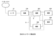
図1は本実施の形態のシステム全体の概要を示した図である。
ここでは、4台の映像機器100,200,300,400を用意する。ここでは、第1の映像機器100は、テレビジョン受像機としてあり、第2の映像機器200は、ビデオ記録再生装置を想定している。第3の映像機器300と第4の映像機器400についても、映像及び音声の記録や再生などを行う映像機器又は音声機器である。
[1. Example of overall system configuration: Fig. 1 and Fig. 2]
FIG. 1 is a diagram showing an overview of the entire system of the present embodiment.
Here, four
4台の映像機器100〜400は、それぞれのHDMI規格の端子(以下HDMI端子と称する)を備えて、それぞれをHDMI用伝送ケーブル90で接続させることが可能としてある。HDMI端子は、映像データ及び音声データの出力端子である場合と、映像データ及び音声データの入力端子である場合とがあるが、いずれの場合でも、映像データや音声データなどの入出力対象のデータの制御に関する制御データについては入力と出力の双方が可能である。
The four
図1の例では、テレビジョン受像機である第1の機器100のHDMI端子(入力端子)を、HDMI用伝送ケーブル90を使って、第3の機器300のHDMI端子(出力端子)に接続してある。また、第3の機器300のHDMI端子(入力端子)を、HDMI用伝送ケーブル90を使って、第2の機器200のHDMI端子(出力端子)に接続してある。さらに、第3の機器300のHDMI端子(入力端子)を、HDMI用伝送ケーブル90を使って、第4の機器400のHDMI端子(出力端子)に接続してある。
In the example of FIG. 1, the HDMI terminal (input terminal) of the
本例の場合には、それぞれのHDMI用伝送ケーブル90では、HDMIネットワークを構成すると同時に、IPアドレスに基づいてパケット(IPパケット)を伝送するIPネットワークについても構成されるようにしてある。そのHDMI用伝送ケーブルを使ってIPネットワークを構成させる具体的な例については後述する。
In the case of this example, each
また、テレビジョン受像機である第1の機器100は、LAN接続を行うためのネットワーク端子を備えて、そのLAN端子にLANケーブル11を介してルータ10が接続してある。ルータ10は、LANケーブル12を介してインターネットと接続される。
The
ここで、図1の構成における、IPネットワークでのネットワーク構成と、HDMIネットワークでのネットワーク構成とを、それぞれ図2に個別に示す。
図2(a)は、IPネットワークでの構成を示したものである。
IPネットワークでは、ルータ10から各機器100〜400が順に接続してあり、ルータ10を経由して、インターネット側ともデータの伝送が行える。このため、ルータ10では、IPネットワーク内の各機器100〜400に対して、それぞれ別のIPアドレスを付与する。IPネットワークでデータを伝送させる際には、各パケット(IPパケット)に送付先のIPアドレスを付与する。送付先として付与されるIPアドレスがインターネット上の外部のアドレスである場合には、伝送対象のデータは、ルータ10からインターネットを経由して、外部の機器(サーバやクライアントなど)に伝送される。
ルータ10については、固定的に各機器にIPアドレスを付与する場合と、随時IPアドレスを変更する場合のいずれでもよい。基本的にネットワーク構成が変わるとIPアドレスも変化する可能性が高いが、ここでのネットワーク構成の変化には、例えばIPネットワーク内のいずれかの機器の電源が完全にオフ状態になるような場合も含まれる。
Here, the network configuration in the IP network and the network configuration in the HDMI network in the configuration of FIG. 1 are individually shown in FIG.
FIG. 2A shows a configuration in an IP network.
In the IP network, the
The
図2(b)は、HDMIネットワークでの構成を示したものである。
HDMIネットワークでは、HDMI用伝送ケーブル90で直接接続した4台の機器100〜400の間で映像データ及び音声データの伝送と、制御データの伝送が行える。HDMIネットワークでのアドレス(HDMIアドレス)としては、第1の機器100などのネットワーク内での基幹となる1台の機器が、ケーブル90の接続状態の変化などを検出するごとに付与する。図2(b)では、テレビジョン受像機である第1の機器100が付与した例である。例えば、第1の機器100としてHDMIアドレス“0.0.0.0”、第2の機器200としてHDMIアドレス“1.1.0.0”、第3の機器300としてHDMIアドレス“1.0.0.0”、第4の機器400としてHDMIアドレス“1.1.1.0”とする。HDMIアドレスは一例であり、また第1の機器100以外のネットワーク内の機器が付与してもよい。HDMIアドレスは、HDMI用伝送ケーブル90で接続した機器の構成が変わらない限り、同じアドレスが維持される。
FIG. 2B shows a configuration in the HDMI network.
In the HDMI network, video data and audio data can be transmitted and control data can be transmitted between the four
本実施の形態においては、このHDMIネットワークとIPネットワークの双方に接続可能なそれぞれの映像機器100〜400で、HDMIアドレスとIPアドレスの対応を示すアドレステーブルのデータを生成させて、機器内のメモリが記憶する。このアドレステーブルは、IPアドレスが変化するごとに更新される。アドレステーブルの具体例については後述する。
In the present embodiment, each
[2.ネットワーク上の機器の構成例:図3]
次に、ネットワークに接続される各機器の構成について説明する。ここでは、第1の機器100を構成するテレビジョン受像機を例にして説明する。
第1の機器であるテレビジョン受像機100は、地上波アンテナ101が接続されるアナログ放送受信用のアンテナ入力端子102aと、デジタル放送受信用アンテナ106が接続されるデジタル放送受信用アンテナ入力端子107aを有する。
[2. Example of device configuration on network: Fig. 3]
Next, the configuration of each device connected to the network will be described. Here, a television receiver constituting the
The
地上アナログ放送用アンテナ入力端子102aから入力された放送波信号は、地上波用アナログチューナ102で、映像および音声信号がベースバンドに復調される。受信して得た映像信号はビデオデコーダ103で、デジタルコンポーネントデータに変換される。受信して得た音声信号は、音声用アナログ/デジタル変換器104にてデジタル信号に変換される。
The broadcast wave signal input from the terrestrial analog broadcast
デジタル放送用アンテナ入力端子107aから入力された放送波信号は、デジタル復調用チューナ107で、MPEG−TSストリームに変換される。MPEG−TSストリームはMPEGデコーダ108に供給して、映像データはデジタルコンポーネントデータに、音声データはデジタル音声データとされる。
The broadcast wave signal input from the digital broadcast
それぞれ変換された映像データは映像処理回路105に供給して、種々の映像処理を行った後、グラフィック生成回路109に供給する。グラフィック生成回路109では、テレビジョン受像機100の操作で必要なグラフィック画面を生成し、映像データに重畳又は映像データに差し替える。コンテンツリストなどのユーザインターフェイス画面についても、このグラフィック生成回路109にて作成される。グラフィック生成回路109が出力する映像データは、パネル駆動回路110に供給する。パネル駆動回路110は、供給される映像データに基づいて表示パネル111での表示駆動を行い、表示パネル111で映像を表示させる。
The converted video data is supplied to the
また、変換された音声データは、音声処理回路112に供給し、各種音声処理を行った後、音声増幅回路113に供給し、必要な音量に調整した後、スピーカ114から出力させる。
The converted audio data is supplied to the
このテレビジョン受像機100での各種処理は、受像機全体の動作制御を行うCPU117の制御で実行される。CPU117での制御に必要なソフトウェア(プログラム)は、フラッシュROM118に記憶させてあり、SDRAM119を使用してソフトウェアが実行される。これらのCPU117とメモリ118,119は、内部バス122により接続されている。外部から入力されたコンテンツリストなどのデータについても、CPU117の制御でSDRAM119又はフラッシュROM118を使用して記憶させるようにしてある。記憶されたコンテンツリストなどのデータは、CPU117の制御で読み出して、グラフィック生成回路109でユーザインターフェイス画面を生成させるようにしてある。
Various processes in the
また、本例のテレビジョン受像機100は、リモートコントロール信号の受光部(受信部)120を備え、別体のリモートコントロール装置121から送信されるリモートコントロール信号(赤外線信号)を受光(受信)して、そのリモートコントロール信号で指示された制御指令を、CPU117に送る構成としてある。
The
本例のテレビジョン受像機100は、外部入力端子として、HDMI端子115とネットワーク端子124とを備える。HDMI端子115は、ベースバンドの映像データなどを入力する端子であり、入力されたデジタルベースバンドデータは、HDMI伝送部116で入力処理されて、映像データについては、映像処理回路105に供給し、音声データについては音声処理回路112に供給し、それぞれの回路105,112で処理を行った後、映像表示及び音声出力が行われる。
The
ネットワーク端子124は、イーサネット(登録商標)などのIPネットワークに接続する端子であり、ネットワークインターフェイス部123に接続してある。CPU117の制御により、ネットワークインターフェイス部123が、ネットワーク端子124を介して接続された他の機器とデータ転送処理を行う。
The
ここで本実施の形態においては、HDMI伝送部116で、HDMI端子115に接続されたHDMI用伝送ケーブル90を使ったHDMIネットワークについての伝送処理を行う。さらに、HDMI伝送部116で、HDMI端子115に接続されたHDMI用伝送ケーブル90の一部のラインを使った、IPネットワークの伝送処理についても行う。このため、HDMI伝送部116は、ネットワークインターフェイス部123とデータ転送を行って、ネットワークインターフェイス部123からIPネットワークで送出するデータの供給を受けると共に、IPネットワークを介して受信したデータをネットワークインターフェイス部123に供給する。
Here, in the present embodiment, the
これらの処理は、CPU117からの制御に基づいて実行される。CPU117には、HDMIネットワーク制御処理機能部131とIPネットワーク制御処理機能部132が少なくとも構成されて、それぞれHDMIネットワーク制御処理機能部131とIPネットワーク制御処理機能部132の制御で、各ネットワークでのデータ伝送が実行される。HDMIネットワーク制御処理機能部131とIPネットワーク制御処理機能部132は、ハードウェアで専用の制御部を構成させる場合の他に、ソフトウェア的にそれぞれの処理機能部として構成される場合もある。また、HDMIネットワーク制御処理機能部131とIPネットワーク制御処理機能部132は、それぞれのネットワーク(HDMIネットワーク、IPネットワーク)で使用するネットワーク内のアドレス(HDMIアドレス、IPアドレス)を記憶するアドレステーブルを生成させて、SDRAM119或いはフラッシュROM118の一部の記憶領域を使って記憶させる。ここでいうアドレステーブルは、HDMIネットワーク制御処理機能部131とIPネットワーク制御処理機能部132がそれぞれ使用する各アドレスに基づいて、CPU117により生成される。ネットワーク上の各機器がデータ伝送を行う際には、そのアドレステーブルのデータを参照して、送信先や受信元のアドレスや機器を判断する。各ネットワークで送出させるコマンドについては、CPU117内のHDMIネットワーク制御処理機能部131又はIPネットワーク制御処理機能部132で生成される。受信したコマンドの判定と、その判定したコマンドに基づいた処理も、HDMIネットワーク制御処理機能部131又はIPネットワーク制御処理機能部132で実行される。
These processes are executed based on the control from the
また、本例においては、機器100の電源のオン・オフとして、HDMIネットワークでの通信を行うのに必要な通信機能部だけの電源を、機器100全体の電源オン・オフとは独立して制御できる構成としてある。同様に、IPネットワークでの通信を行うのに必要な機能部だけの電源についても、機器100全体の電源オン・オフとは独立して制御できる構成としてある。
Further, in this example, as the power of the
なお、第1の機器100以外の機器200〜400の構成については、省略するが、ネットワークに接続するための基本的な構成は同じである。但し、他の機器200〜400については、HDMI端子だけを備えて、ネットワーク端子124については省略してある場合もある。
Although the configurations of the
[3.HDMIネットワークの伝送状態の詳細:図4]
次に、図4を参照して、HDMI用伝送ケーブル90でデータを伝送させる構成例について説明する。この図4の例では、第1の機器100と第3の機器300との間を接続したHDMI用伝送ケーブル90について示してある。
[3. Details of transmission status of HDMI network: Fig. 4]
Next, a configuration example in which data is transmitted through the
HDMI規格では、図4に示すように、映像データを伝送するチャンネルとして、チャンネル0と、チャンネル1と、チャンネル2の3つのチャンネルが用意してあり、さらにピクセルクロックを伝送するクロックチャンネルが用意してある。それぞれのチャンネルのデータが、個別のライン91,92,93,94で伝送される。
各チャンネルのデータは、送出側の機器300のHDMI伝送部301内のチャンネル合成部301a,301b,301cで、画素データと、垂直同期データ及び水平同期データと、補助データとを合成して送出させる。受信側の機器100のHDMI伝送部116内のチャンネル分離部116a,116b,116cで、画素データと、垂直同期データ及び水平同期データと、補助データとを分離する。
In the HDMI standard, as shown in FIG. 4, three channels of
The data of each channel is transmitted by combining the pixel data, the vertical synchronization data, the horizontal synchronization data, and the auxiliary data in the
チャンネル0では、Bデータ(青色データ)の画素データと、垂直同期データと水平同期データと補助データとを伝送するようにしてある。チャンネル1では、Gデータ(緑色データ)の画素データと、2種類の制御データ(CTL0,CTL1)と、補助データとを伝送するようにしてある。チャンネル2では、Rデータ(赤色データ)の画素データと、2種類の制御データ(CTL2,CTL3)と、補助データとを伝送するようにしてある。
In
また、電源の伝送ライン95と、制御データ伝送チャンネルとしての、DDCライン96及びCECライン97が用意してある。DDC(Display Data Channel)は、主として表示制御のためのデータチャンネルであり、CEC(Consumer Electronics Control)は、主としてケーブルで接続された相手の機器を制御するためのデータチャンネルである。
In addition, a
さらに本例においては、HDMI用伝送ケーブル90内の空いている特定のライン及び兼用が可能なラインを、IPパケット伝送用ライン98として使用する。なお、通常LANのネットワークでIPパケットを双方向に伝送させる場合、一方から他方への伝送用のラインと、他方から一方への伝送用のラインは個別のものが使用されるが、本例の場合には、双方向の信号を重畳して1つのライン98を共通に使用する。
Further, in this example, a specific line that is available in the
[4.アドレステーブルの例:図5]
次に、各機器のメモリ(機器100のSDRAM119など)に記憶されるアドレステーブルの例について説明する。
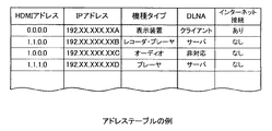
図5に示すように、アドレステーブルとしては、HDMIアドレスと、IPアドレスの対応を、少なくともHDMIネットワーク上の全ての機器について記憶させてある。また、IPネットワーク上での制御コマンドなどのやり取り、又はHDMIネットワーク上での制御コマンドなどのやり取りにより判別した、ネットワーク上の各機器の機種タイプについての情報についても記憶させてある。具体的には、図1のネットワーク構成の場合、機種タイプとして、機器100:表示装置、機器200:記録再生装置、機器300:オーディオ処理装置、機器400:再生装置として記憶させてある。より詳細な機種タイプを判別して、記憶させてもよい。後述するDLNA方式でのサーバとなる機器か、クライアントとなる機器か、DLNA方式に非対応の機器かの区別についても、記憶させてある。この各機器が、DLNA方式でのサーバとなる機器か、クライアントとなる機器か、DLNA方式に非対応の機器かの区別は、HDMIネットワーク上のCECライン97(図4)で伝送されるコマンドに基づいて収集されたデータである。
また、各機器は、インターネット接続機能を有する機器か、インターネット接続機能を有さない機器かを示す種別を記憶するようにしてある。ここでのインターネット接続機能とは、例えば、図3に示した第1の機器100が備えたネットワーク接続端子124のように、直接ルータなどに接続できる端子などを備えた機器である。また、無線でインターネットに接続できる機器であってもよい。
この図5に示したアドレステーブルは、IPネットワークとHDMIネットワークの双方に接続可能な全ての機器、言い換えると、HDMI用伝送ケーブル90でHDMIネットワークとIPネットワークの双方に接続される全ての機器が、備える。
[4. Example of address table: Fig. 5]
Next, an example of an address table stored in the memory of each device (such as the
As shown in FIG. 5, in the address table, the correspondence between the HDMI address and the IP address is stored for at least all devices on the HDMI network. In addition, information about the model type of each device on the network determined by the exchange of control commands on the IP network or the exchange of control commands on the HDMI network is also stored. Specifically, in the case of the network configuration of FIG. 1, the device type is stored as device 100: display device, device 200: recording / playback device, device 300: audio processing device, device 400: playback device. A more detailed model type may be determined and stored. The distinction between a device that becomes a server in the DLNA method, a device that becomes a client, and a device that does not support the DLNA method, which will be described later, is also stored. Whether each device is a DLNA server device, a client device, or a device that does not support the DLNA method is determined by a command transmitted on the CEC line 97 (FIG. 4) on the HDMI network. Data collected on the basis.
Each device stores a type indicating whether the device has an Internet connection function or a device that does not have an Internet connection function. The Internet connection function here is, for example, a device provided with a terminal that can be directly connected to a router or the like, such as the
The address table shown in FIG. 5 includes all devices that can be connected to both the IP network and the HDMI network, in other words, all devices connected to both the HDMI network and the IP network by the
[5.ネットワーク上の他の機器でコンテンツを再生させる例:図6,図7]
次に、各ネットワークを使用してデータ伝送を行う例について説明する。ここでは、IPネットワークでは、コンテンツの伝送規格(ガイドライン)である、DLNA(Digital Living Network Alliance)ガイドライン(以下DLNA方式と称する)に従って、映像コンテンツや音声コンテンツを送受信できるようにしてある。
[5. Example of playing content on other devices on the network: FIGS. 6 and 7]
Next, an example in which data transmission is performed using each network will be described. Here, in an IP network, video content and audio content can be transmitted and received in accordance with DLNA (Digital Living Network Alliance) guidelines (hereinafter referred to as DLNA system), which are content transmission standards (guidelines).
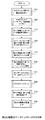
図6のフローチャートは、図1に示したネットワーク構成において、ネットワーク上の全ての機器が電源オフの状態から、必要な機器の電源を投入させて、図1に示した第2の機器200で映像コンテンツを再生して、第1の機器100に伝送させる例である。第1の機器100で受信した映像コンテンツとその映像コンテンツに付随した音声データは、テレビジョン受像機である機器100で映像表示処理及び音声出力処理が行われる。
この第2の機器200から第1の機器100への映像コンテンツのデータの伝送は、ここでは、DLNA方式に従って、IPネットワークでIPパケットとして伝送させるものとする。
The flowchart of FIG. 6 shows the video image of the
Transmission of video content data from the
図6のフローチャートの処理について順に説明すると、まず、初期状態ではHDMIネットワーク上の全ての機器は電源オフとなって、スタンバイ状態であるとする。ここでは、各機器は、電源オフの状態のとき、HDMIネットワークの通信機能部での通信は可能であり、IPネットワークの通信機能部での通信は出来ない状態である。IPネットワークで通信を行うためには、少なくともIPネットワークの通信機能部の電源を投入させる必要がある。 The processing in the flowchart of FIG. 6 will be described in order. First, in an initial state, all devices on the HDMI network are turned off and are in a standby state. Here, when the power is turned off, each device can communicate with the communication function unit of the HDMI network and cannot communicate with the communication function unit of the IP network. In order to communicate on the IP network, it is necessary to power on at least the communication function unit of the IP network.
この各機器が電源オフの状態で、ユーザがリモートコントロール装置121(図3)の電源キーなどを操作して、第1の機器100の電源をオフ状態からオン状態に変化させたとする(ステップS11)。そして、同じくユーザ操作で、DLNA方式で他の機器(サーバ)が蓄積したコンテンツを再生させる指定を行ったとする(ステップS12)。このとき、アドレステーブル上のデータに基づいて、DLNA方式でサーバとなる機器のリストを表示させ(ステップS13)、その表示の中からユーザ操作で機器を選択させる(ステップS14)。ここでは第2の機器200を選択したとする。DLNA方式はIPネットワークを使った伝送処理であるので、IPアドレスを使ってリスト上の機器が判断されるが、ここで図5に示したアドレステーブルを使って、選択された機器のHDMIアドレスに対応したIPアドレスについても判断される。
It is assumed that the power of the
そして、第1の機器100は、選択された機器である第2の機器200に対して、HDMIネットワークでHDMIアドレスを使ってアクセスを行う(ステップS15)。また、第1の機器100と第2の機器200との間にある機器、ここでは第3の機器300についても、HDMIネットワークを使った指令で、IPネットワーク機能の電源を投入させる(ステップS16)。
Then, the
そして、選択されたサーバである第2の機器200の電源をオンさせ(ステップS17)、HDMIネットワークでの通信で、第1の機器100と第2の機器200との間で、IPアドレスを交換して現在のIPアドレスを確認する(ステップS18)。このとき、確認したIPアドレスが、自機のアドレステーブルに記憶されたIPアドレスと異なるときには、記憶データを更新させておく。
Then, the power supply of the
ここまでの処理が行われると、第1の機器100から第2の機器200に対して、ステップS18によって得られたIPアドレスによるIPネットワークでのIPプロトコルによる接続を開始させ(ステップS19)、第1の機器100と第2の機器200との間を、DLNA方式による手順で接続させる(ステップS20)。その後、DLNA方式で規定された手順に従って、第2の機器200が持つコンテンツリストを第1の機器で表示させて、そのリストから再生するコンテンツを選択させる(ステップS21)。その選択されたコンテンツを、第2の機器200から第1の機器100に対して送り、第1の機器100で映像の表示及び音声の出力を行う(ステップS22)。
When the processing so far is performed, the
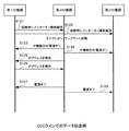
図7は、この図6のフローチャートの処理の中で、HDMIネットワークのCECラインで行われる処理例を示したものである。CECラインは、既に説明したように、HDMIネットワークの制御データのやり取りを行うラインである。
図6のフローチャートの処理が行われる前段階の処理として、第1の機器100と第2の機器200と第3の機器300は、HDMIネットワークで通信を行った際に、予めDLNA方式でのサーバかクライアントかを報告しておく。
即ち、第2の機器200は第1の機器100に対してDLNA方式でのサーバであると報告し(ステップS101)、さらに第3の機器300に対してもDLNA方式でのサーバであると報告する(ステップS102)。
また、第1の機器100は第2の機器200に対してDLNA方式でのクライアントであると報告し(ステップS103)、さらに第3の機器300に対してもDLNA方式でのクライアントであると報告する(ステップS104)。このサーバかクライアントかの報告は、CECラインを使って行われ、いつ行うようにしてもよい。その報告された種別は、アドレステーブルに記憶させておく。
FIG. 7 shows an example of processing performed on the CEC line of the HDMI network in the processing of the flowchart of FIG. As described above, the CEC line is a line for exchanging control data of the HDMI network.
The
That is, the
Also, the
ここまでの処理が前段階として行われ、各機器の電源がオフの状態で、第1の機器100に対してユーザ操作で、電源オンとDLNA再生が指示されたとする(ステップS105)。この指示は、例えばリモートコントロール装置121(図3)を使って行われる。その操作に基づいて、サーバのリスト表示が行われ(ステップS106)、その表示に基づいて第2の機器200をユーザが選択したとする(ステップS107)。
It is assumed that the processing up to this point is performed as a previous stage, and the power on and DLNA reproduction are instructed by the user operation to the
この選択が行われると、CECラインを使って、第1の機器100から第3の機器300に対して、IPネットワークでの通信機能をオンさせる電源オンコマンドを送り(ステップS108)、第3の機器300のIPネットワーク通信機能部だけを電源オンさせる。さらに、CECラインを使って、第1の機器100から第2の機器200に対して、電源オンコマンドを送り(ステップS109)、第2の機器200の各機能を起動させる。
When this selection is made, a power-on command for turning on the communication function in the IP network is sent from the
その後、第2の機器200から第1の機器100に対して、CECラインを使ってIPアドレスを報告させ(ステップS110)、第1の機器100から第2の機器200に対して、CECラインを使ってIPアドレスを報告させる(ステップS111)。ここまでがHDMIネットワークでの処理であり、以後は図6のフローチャートで説明したように、IPネットワークでの処理に移る。
Thereafter, the
なお、図7のシーケンス図では、CECラインを使って伝送される制御コマンドとして、電源オンコマンドを示したが、処理が終了した後に、該当する機器の電源をオフさせる電源オフコマンドを送るようにしてもよい。この電源オフコマンドの場合にも、機器全体をスタンバイ状態とするコマンドと、IPネットワークでの通信機能部を電源オフとするコマンドを用意してもよい。或いは、電源オフコマンドの場合には、1つのコマンドを共通に使ってもよい。 In the sequence diagram of FIG. 7, a power-on command is shown as a control command transmitted using the CEC line. However, after the processing is completed, a power-off command for turning off the power of the corresponding device is sent. May be. Also in the case of this power off command, a command for setting the entire device in a standby state and a command for powering off the communication function unit in the IP network may be prepared. Alternatively, in the case of a power off command, one command may be used in common.
[6.ネットワーク上の機器がインターネットを介してアップデートする例:図8,図9]
次に、IPネットワークを使って、第2の機器200が第2の機器200に組み込まれたソフトウェアをアップデートさせる処理例を、図8及び図9を参照して説明する。この場合には、IPネットワークに接続された第2の機器200が、外部のインターネットを経由して、アップデート用のソフトウェアが記憶されたサーバにアクセスするものである。この場合にも、最初の状態ではネットワーク上に接続された各機器は電源オフであるとする。
[6. Example in which devices on the network update via the Internet: Fig. 8 and Fig. 9]
Next, an example of processing in which the
図8に従って説明すると、まず第2の機器200は、機器200自身に組み込まれたタイマ機能で電源オンさせ(ステップS31)、HDMIネットワークを使って、HDMIアドレスで、インターネットに接続するための機器へアクセスする(ステップS32)。ここでの「インターネットに接続するための機器」とは、図5のアドレステーブルで得られるように、図1のルータ10に直接接続された第1の機器100である。
そして、第2の機器200は、第1の機器100に対して、HDMIネットワークのCECラインを使って、IPネットワーク通信機能部を電源オンとさせるコマンドを送り、第1の機器100の該当するインターネットへの接続機能部を電源オンさせる(ステップS33)。さらに、第2の機器200は、第2の機器200と第1の機器100の経路の途中に位置する第3の機器300に対しても、IPネットワーク通信機能部を電源オンとさせるコマンドを送り、第3の機器300の該当する機能部を電源オンさせる(ステップS34)。
Referring to FIG. 8, first, the
Then, the
その後、第2の機器200と第1の機器100は、各機器の間で、HDMIネットワークのCECラインを使って、IPアドレスを交換させて確認する(ステップS35)。そして、第2の機器100は、第2の機器100から第1の機器100を経由して、IPネットワークでインターネットに接続させ、外部のサイトにアクセスする(ステップS36)。第2の機器100は、第1の機器100を介して、その外部のサイトからアップデートソフトのデータをダウンロードし(ステップS37)、そのダウンロードしたデータで機器200内のソフトウェアをアップデートする(ステップS38)。
Thereafter, the
ここまでの処理が完了すると、第2の機器200は、HDMIネットワークのCECラインを使って、第1の機器100と第3の機器300に対して、電源オフコマンドを送り、それぞれの機器をスタンバイ状態とする(ステップS39)。さらに、最後に自機である第2の機器200についても、電源オフとしてスタンバイ状態とする(ステップS40)。
When the processing up to this point is completed, the
図9は、この図8のフローチャートの処理の中で、HDMIネットワークのCECラインで行われる処理例を示したものである。
図8のフローチャートの処理が行われる前段階の処理として、第1の機器100は、HDMIネットワークで通信を行った際に、予めインターネット接続機能がある機器であることを、各機器にCECラインで報告しておく(ステップS121,S122)。
その報告されたインターネット接続機能がある機器は、アドレステーブルなどに記憶させておく。即ち、図5のアドレステーブルに示したように、インターネット接続機能の「あり」又は「なし」を、各機器の覧に記憶させておく。
アップデートが必要なタイミングになると、そのアップデートが必要な第2の機器200は、HDMIネットワークのCECラインを使って、第1の機器100と第3の機器300に対して、電源オンさせるコマンドを送信する(ステップS123,S124)。この電源オンコマンドは、IPネットワークの通信機能部をオンさせるコマンドである。その後、第1の機器100と第2の機器200との間で、CECラインを使ってIPアドレスの報告を相互に行い(ステップS125,S126)、その確認したIPアドレスを使ってIPネットワークでインターネットに接続するための通信を行う。
FIG. 9 shows an example of processing performed on the CEC line of the HDMI network in the processing of the flowchart of FIG.
As a process before the process of the flowchart of FIG. 8 is performed, the
The reported device having the Internet connection function is stored in an address table or the like. That is, as shown in the address table of FIG. 5, “Yes” or “No” of the Internet connection function is stored in the list of each device.
When it is time to update, the
さらに、アップデート処理が終了した後に、第2の機器200から第1の機器100と第3の機器300に、CECラインを使って電源オフコマンドを送信し、各機器の電源をオフさせる(ステップS127,S128)。
Further, after the update process is completed, a power-off command is transmitted from the
[7.複数の経路がある例:図10]
図1のネットワーク構成では、データを伝送する経路が一義的に決まるが、複数の経路が存在する場合には、その経路の選択についても、HDMIネットワークのCECラインを使って機器の状態を確認した上で、IPネットワークでデータ伝送を行う経路を選択するようにしてもよい。
即ち、例えば図10に示すように、第1の機器100と第2の機器200との間のHDMI用伝送ケーブルでの接続として、第3の機器300を介した経路Aの接続と、第5の機器500を介した経路Bの接続とが行われるとする。いずれのHDMI用伝送ケーブルについても、IPネットワークでの通信機能も備えた接続である。
[7. Example with multiple routes: FIG. 10]
In the network configuration of FIG. 1, the route for transmitting data is uniquely determined. However, when there are a plurality of routes, the state of the device is also confirmed using the CEC line of the HDMI network when selecting the route. In the above, a route for performing data transmission in the IP network may be selected.
That is, for example, as shown in FIG. 10, as the connection with the HDMI transmission cable between the
この状態で、第2の機器200が、第1の機器100とIPネットワークで通信をしたい場合に、経路Aの途中にある第3の機器300が稼働中で、データの中継に支障がある可能性があるとする。このとき、第2の機器200では、経路Bを選択し、第5の機器500に対して、HDMIネットワークのCECラインを使って電源オンコマンドを送って、IPネットワークの通信機能部をオンさせ、経路Bで通信を開始させる。
このようにすることで、IPネットワークの経路が複数存在する場合の選択についても、HDMIネットワーク側で判断した結果に基づいて、行えるようになる。
In this state, when the
In this way, selection in the case where there are a plurality of IP network paths can be performed based on the result determined on the HDMI network side.
[8.実施の形態の効果]
以上説明したように、本実施の形態の形態によると、HDMIネットワークとIPネットワークの2つのネットワークで接続された場合に、IPネットワークで伝送を行う上での機器選択などが簡単かつ確実に行えるようになる。従って、IPネットワークでのアドレスが随時変更されるような場合であっても、ネットワーク上の各機器を特定して、所望の機器に確実にデータ伝送が行えるようになる。
[8. Effects of the embodiment]
As described above, according to the present embodiment, when two networks, the HDMI network and the IP network, are connected, it is possible to easily and reliably select a device for transmission on the IP network. become. Therefore, even when the address in the IP network is changed as needed, each device on the network is specified, and data transmission can be reliably performed to a desired device.
また、IPネットワークでの伝送路の途中の機器が、電源オフなどの理由で伝送に障害がある場合でも、HDMIネットワーク側のアドレスで、その障害となっている機器がどの機器か判るようになる。このため、HDMIネットワークを使った制御で、該当する機器を起動させるなどの障害を除く処理が可能となり、常時IPネットワークで通信可能に待機しておく必要がなくなり、各機器の低消費電力化に貢献する。 Further, even when a device in the middle of a transmission path in an IP network has a transmission failure due to power-off or the like, the address on the HDMI network side can identify which device is the failure. . For this reason, control using the HDMI network enables processing to eliminate troubles such as starting up the corresponding device, eliminating the need to always stand by for communication on the IP network, and reducing power consumption of each device. To contribute.
[9.変形例の説明]
なお、上述した実施の形態では、HDMI用の伝送ライン内の特定のラインを使って、IPネットワークでの伝送が行われるようにし、2つのネットワークが1種類の伝送ラインで接続される構成とした。これに対して、それぞれのネットワークが別の伝送ラインで接続されたものに対して、同様の処理を行うようにしてもよい。2つのネットワークの少なくともいずれか一方が、無線接続で構成されるネットワークであってもよい。
2つのネットワークについても、一方のネットワーク(第1のネットワーク)が、HDMIネットワークで、他方のネットワーク(第2のネットワーク)が、IPネットワークとしたが、それぞれその他のシステム構成のネットワークとしてもよい。
[9. Description of modification]
In the above-described embodiment, the transmission is performed on the IP network using a specific line in the HDMI transmission line, and the two networks are connected by one type of transmission line. . On the other hand, the same processing may be performed for each network connected by another transmission line. At least one of the two networks may be a network configured by wireless connection.
As for the two networks, one network (first network) is an HDMI network and the other network (second network) is an IP network. However, each network may have other system configurations.
なお、上述した実施の形態では、テレビジョン受像機などの映像機器や音声機器が、2つのネットワークに接続可能な伝送装置として機能するようにしたが、例えば各種データ処理を行うパーソナルコンピュータ装置(情報処理装置)に適用してもよい。この場合には、パーソナルコンピュータ装置として、本例の各ネットワーク接続端子とネットワーク通信処理機能部を備える。そして、アドレステーブルに相当するデータを記憶させて、その2つのネットワーク通信機能部を連携させて処理を実行させるソフトウェア(プログラム)を、パーソナルコンピュータ装置に実装させればよい。 In the above-described embodiment, the video device and the audio device such as a television receiver function as a transmission device that can be connected to two networks. However, for example, a personal computer device (information (Processing apparatus). In this case, each network connection terminal and network communication processing function unit of this example are provided as a personal computer device. Then, data corresponding to the address table may be stored, and software (program) for executing processing in cooperation with the two network communication function units may be mounted on the personal computer device.
10…ルータ、11,12…LANケーブル、90…HDMI用伝送ケーブル、91…チャンネル0のライン、92…チャンネル1のライン、93…チャンネル2のライン、94…クロックチャンネルのライン、95…電源ライン、96…DDCライン、97…CECライン、98…IPパケット用ライン、100…第1の機器(テレビジョン受像機)、
101…地上波用アンテナ、102…地上波チューナ、103…ビデオデコーダ、104…音声用アナログ/デジタル変換器、105…映像処理回路、106…デジタル放送用アンテナ、107…MPEGデコーダ、109…グラフィク生成回路、110…パネル駆動回路、111…表示パネル、112…音声処理回路、113…音声増幅回路、114…スピーカ、115…HDMI端子、116…HDMI伝送処理回路、117…CPU、118…フラッシュROM、119…SDRAM、120…赤外線信号受光部、121…リモートコントロール装置、123…ネットワークインターフェイス部、124…ネットワーク端子、200…第2の機器、300…第3の機器、400…第4の機器、500…第5の機器
DESCRIPTION OF
DESCRIPTION OF
Claims (7)
ルーティング機能を有する機器により付与された第2のアドレスを使って、コンテンツデータ及び/又は制御データの伝送が可能な第2のネットワークへの接続を制御する第2のネットワーク接続制御部と、
前記第1のネットワーク接続制御部を介して接続された第1のネットワーク上の機器の前記第1のアドレスと、前記第2のネットワーク接続部を介して接続された第2のネットワーク上の機器の前記第2のアドレスとを対応付けて記憶するアドレステーブルと
を備えた伝送装置。 A first network connection control unit that controls connection to a first network capable of transmitting content data and / or control data using a first address assigned by a backbone device in the network;
A second network connection control unit that controls connection to a second network capable of transmitting content data and / or control data using a second address assigned by a device having a routing function;
The first address of the device on the first network connected via the first network connection control unit and the device on the second network connected via the second network connection unit A transmission device comprising: an address table that stores the second address in association with each other.
請求項1記載の伝送装置。 The first network connection control unit transmits, via the first network, a first command that activates a communication function unit that communicates with the second network to other devices on the network. The transmission apparatus according to claim 1, which is possible.
請求項2記載の伝送装置。 The first network connection control unit transmits, via the first network, a second command for stopping a communication function unit that communicates with the second network to other devices on the network. The transmission apparatus according to claim 2, which is made possible.
前記第2のネットワーク接続制御部は、前記伝送ラインの第3の信号線を使って接続制御する
請求項3記載の伝送装置。 The first network connection control unit is used for at least a first signal line for transmitting content data as video data and audio data, a second signal line for transmitting control data, and other processing. Connection control by a transmission line having three signal lines,
The transmission apparatus according to claim 3, wherein the second network connection control unit performs connection control using a third signal line of the transmission line.
前記第2のネットワークは前記第2のアドレスとしてIPアドレスを使ったネットワークであり、前記第2のネットワークを介して外部とデータ伝送が可能なネットワークである
請求項1ないし4のいずれか1項に記載の伝送装置。 The first network is a network connected by an HDMI standard transmission line;
5. The network according to claim 1, wherein the second network is a network using an IP address as the second address, and is a network capable of transmitting data to and from the outside via the second network. The transmission device described.
ルーティング機能を有する機器により付与された第2のアドレスを使って、コンテンツデータ及び/又は制御データの伝送が可能な第2のネットワークへの接続を制御するステップと、
前記第1のネットワークと前記第2のネットワークの双方に接続された機器についての、前記第1のアドレスと前記第2のアドレスとを対応付けてアドレステーブルに記憶させるステップとを行う
伝送方法。 Controlling a connection to a first network capable of transmitting content data and / or control data using a first address assigned by a backbone device in the network;
Controlling connection to a second network capable of transmitting content data and / or control data using a second address assigned by a device having a routing function;
A transmission method that performs a step of associating and storing the first address and the second address in an address table for devices connected to both the first network and the second network.
ルーティング機能を有する機器により付与された第2のアドレスを使って、コンテンツデータ及び/又は制御データの伝送が可能な第2のネットワークへの接続を制御するステップと、
前記第1のネットワークと前記第2のネットワークの双方に接続された機器についての、前記第1のアドレスと前記第2のアドレスとを対応付けてアドレステーブルに記憶させるステップとを、
情報処理装置である伝送装置に実装させて実行させる
プログラム。 Controlling a connection to a first network capable of transmitting content data and / or control data using a first address assigned by a backbone device in the network;
Controlling connection to a second network capable of transmitting content data and / or control data using a second address assigned by a device having a routing function;
Storing the first address and the second address in an address table in association with each other for devices connected to both the first network and the second network;
A program that is implemented by a transmission device that is an information processing device.
Priority Applications (4)
| Application Number | Priority Date | Filing Date | Title |
|---|---|---|---|
| JP2008255452A JP4743250B2 (en) | 2008-09-30 | 2008-09-30 | Transmission apparatus, transmission method and program |
| EP09252007.1A EP2169919B1 (en) | 2008-09-30 | 2009-08-18 | Transfer device, transfer method, and program providing address mapping between hdmi and ip |
| US12/566,014 US8955023B2 (en) | 2008-09-30 | 2009-09-24 | Transfer device, transfer method, and program |
| CN2009101745608A CN101715096B (en) | 2008-09-30 | 2009-09-28 | Transfer device, transfer method, and program |
Applications Claiming Priority (1)
| Application Number | Priority Date | Filing Date | Title |
|---|---|---|---|
| JP2008255452A JP4743250B2 (en) | 2008-09-30 | 2008-09-30 | Transmission apparatus, transmission method and program |
Publications (2)
| Publication Number | Publication Date |
|---|---|
| JP2010087894A true JP2010087894A (en) | 2010-04-15 |
| JP4743250B2 JP4743250B2 (en) | 2011-08-10 |
Family
ID=41258284
Family Applications (1)
| Application Number | Title | Priority Date | Filing Date |
|---|---|---|---|
| JP2008255452A Expired - Fee Related JP4743250B2 (en) | 2008-09-30 | 2008-09-30 | Transmission apparatus, transmission method and program |
Country Status (4)
| Country | Link |
|---|---|
| US (1) | US8955023B2 (en) |
| EP (1) | EP2169919B1 (en) |
| JP (1) | JP4743250B2 (en) |
| CN (1) | CN101715096B (en) |
Cited By (4)
| Publication number | Priority date | Publication date | Assignee | Title |
|---|---|---|---|---|
| US8661277B2 (en) | 2010-03-24 | 2014-02-25 | Canon Kabushiki Kaisha | Communication apparatus and method of controlling the same |
| JP2015513805A (en) * | 2011-12-29 | 2015-05-14 | エーティーアイ・テクノロジーズ・ユーエルシーAti Technologies Ulc | Method and apparatus for electronic device communication |
| JP2015136157A (en) * | 2015-03-05 | 2015-07-27 | ヤマハ株式会社 | Portable terminal device |
| US9813753B2 (en) | 2012-05-30 | 2017-11-07 | Yamaha Corporation | Core device, audio/video control system, portable terminal device, audio/video control program, and audio/video control method |
Families Citing this family (8)
| Publication number | Priority date | Publication date | Assignee | Title |
|---|---|---|---|---|
| CN102347928B (en) * | 2010-07-29 | 2014-01-15 | 鸿富锦精密工业(深圳)有限公司 | Digital media device and method for realizing shutdown device content sharing by utilizing digital media device |
| US9451331B2 (en) * | 2011-01-15 | 2016-09-20 | Lattice Semiconductor Corporation | Proxy device operation in command and control network |
| CN102231880A (en) * | 2011-07-04 | 2011-11-02 | 中兴通讯股份有限公司 | Version upgrade method and terminal, and version upgrade system |
| US9930404B2 (en) | 2013-06-17 | 2018-03-27 | Echostar Technologies L.L.C. | Event-based media playback |
| US9936248B2 (en) | 2014-08-27 | 2018-04-03 | Echostar Technologies L.L.C. | Media content output control |
| US9565474B2 (en) * | 2014-09-23 | 2017-02-07 | Echostar Technologies L.L.C. | Media content crowdsource |
| US10432296B2 (en) | 2014-12-31 | 2019-10-01 | DISH Technologies L.L.C. | Inter-residence computing resource sharing |
| JP6388014B2 (en) * | 2016-11-14 | 2018-09-12 | オンキヨー株式会社 | Firmware update system, server, and electronic device |
Citations (6)
| Publication number | Priority date | Publication date | Assignee | Title |
|---|---|---|---|---|
| JP2001007861A (en) * | 1999-06-24 | 2001-01-12 | Matsushita Electric Ind Co Ltd | Gateway system |
| JP2006094509A (en) * | 2004-09-21 | 2006-04-06 | Samsung Electronics Co Ltd | Terminal adaptor apparatus capable of ieee 1394 ethernet conversion |
| JP2007311884A (en) * | 2006-05-16 | 2007-11-29 | Sony Corp | Communication system, transmission apparatus and reception apparatus, communication method, and program |
| JP2008034907A (en) * | 2006-07-26 | 2008-02-14 | Sharp Corp | Av apparatus, av system, and power control method |
| WO2008056707A1 (en) * | 2006-11-07 | 2008-05-15 | Sony Corporation | Electronic device, control information transmission method, and control information reception method |
| WO2008056709A1 (en) * | 2006-11-07 | 2008-05-15 | Sony Corporation | Receiver, delayed information transmitting method for receivers, audio output device, and delay control method for audio output devices |
Family Cites Families (7)
| Publication number | Priority date | Publication date | Assignee | Title |
|---|---|---|---|---|
| AU1351400A (en) * | 1999-02-03 | 2000-08-10 | Alcatel | Process, adaption device, network node and switching centre for connecting a telecommunication terminal to the internet |
| JP3648685B2 (en) | 2001-01-30 | 2005-05-18 | 松下電器産業株式会社 | Data transmission method and data transmission apparatus |
| US7126954B2 (en) * | 2001-11-13 | 2006-10-24 | General Instrument Corporation | Virtual gateway |
| US20030131258A1 (en) * | 2002-01-04 | 2003-07-10 | Kadri Seemab Aslam | Peer-to-peer communication across firewall using internal contact point |
| JP2007143059A (en) | 2005-11-22 | 2007-06-07 | Sony Corp | System, apparatus and method for transmitting and receiving video |
| JP2008255452A (en) | 2007-04-09 | 2008-10-23 | Hitachi Cable Ltd | Cooling plate |
| CN101971153B (en) * | 2008-03-14 | 2018-10-09 | 汤姆逊许可证公司 | The methods, devices and systems of peripheral equipment are realized using high-definition multimedia interface |
-
2008
- 2008-09-30 JP JP2008255452A patent/JP4743250B2/en not_active Expired - Fee Related
-
2009
- 2009-08-18 EP EP09252007.1A patent/EP2169919B1/en not_active Not-in-force
- 2009-09-24 US US12/566,014 patent/US8955023B2/en not_active Expired - Fee Related
- 2009-09-28 CN CN2009101745608A patent/CN101715096B/en not_active Expired - Fee Related
Patent Citations (6)
| Publication number | Priority date | Publication date | Assignee | Title |
|---|---|---|---|---|
| JP2001007861A (en) * | 1999-06-24 | 2001-01-12 | Matsushita Electric Ind Co Ltd | Gateway system |
| JP2006094509A (en) * | 2004-09-21 | 2006-04-06 | Samsung Electronics Co Ltd | Terminal adaptor apparatus capable of ieee 1394 ethernet conversion |
| JP2007311884A (en) * | 2006-05-16 | 2007-11-29 | Sony Corp | Communication system, transmission apparatus and reception apparatus, communication method, and program |
| JP2008034907A (en) * | 2006-07-26 | 2008-02-14 | Sharp Corp | Av apparatus, av system, and power control method |
| WO2008056707A1 (en) * | 2006-11-07 | 2008-05-15 | Sony Corporation | Electronic device, control information transmission method, and control information reception method |
| WO2008056709A1 (en) * | 2006-11-07 | 2008-05-15 | Sony Corporation | Receiver, delayed information transmitting method for receivers, audio output device, and delay control method for audio output devices |
Cited By (4)
| Publication number | Priority date | Publication date | Assignee | Title |
|---|---|---|---|---|
| US8661277B2 (en) | 2010-03-24 | 2014-02-25 | Canon Kabushiki Kaisha | Communication apparatus and method of controlling the same |
| JP2015513805A (en) * | 2011-12-29 | 2015-05-14 | エーティーアイ・テクノロジーズ・ユーエルシーAti Technologies Ulc | Method and apparatus for electronic device communication |
| US9813753B2 (en) | 2012-05-30 | 2017-11-07 | Yamaha Corporation | Core device, audio/video control system, portable terminal device, audio/video control program, and audio/video control method |
| JP2015136157A (en) * | 2015-03-05 | 2015-07-27 | ヤマハ株式会社 | Portable terminal device |
Also Published As
| Publication number | Publication date |
|---|---|
| JP4743250B2 (en) | 2011-08-10 |
| EP2169919B1 (en) | 2016-02-17 |
| CN101715096B (en) | 2012-11-14 |
| CN101715096A (en) | 2010-05-26 |
| EP2169919A1 (en) | 2010-03-31 |
| US8955023B2 (en) | 2015-02-10 |
| US20100083327A1 (en) | 2010-04-01 |
Similar Documents
| Publication | Publication Date | Title |
|---|---|---|
| JP4743250B2 (en) | Transmission apparatus, transmission method and program | |
| JP5075279B2 (en) | I / O switching device and I / O switching method | |
| WO2011122456A1 (en) | Sink device, source device and wireless transmission system | |
| JP5013527B2 (en) | AV system and display device | |
| JP5708562B2 (en) | Audio / video control system, portable terminal device, and audio / video control program | |
| JP2005509377A (en) | Method and system for automatic switching between analog and digital input signals | |
| US20090285138A1 (en) | Maintaining wireless communication between Consumer Electronic Control devices | |
| JP2009141537A (en) | Display system, display device and repeater apparatus | |
| US20110167465A1 (en) | Device control apparatus, device control method and computer program | |
| JP2009200788A (en) | Receiving device | |
| JP4917452B2 (en) | Display device and display system | |
| JP4799337B2 (en) | Display device, AV device, and display system including these | |
| JP2008034976A (en) | Display device and system | |
| JP2008145679A (en) | Display apparatus and av system | |
| JP2007306052A (en) | Outputting device, inputting device, transmission system, and transmission method | |
| EP2160023A1 (en) | Broadcast receiving apparatus capable of communicating with external apparatus and method for using content | |
| JP2005210198A (en) | Control system, controller, control method, and program | |
| WO2012172850A1 (en) | Device operating system, display device, and operating device | |
| JP4889610B2 (en) | Display device and display system | |
| US20200213663A1 (en) | Renderer device, renderer playback system and information updating method | |
| JP5172343B2 (en) | Content playback apparatus and content playback method | |
| JP4666384B2 (en) | Recording reservation system | |
| JP5091972B2 (en) | Sink device and wireless transmission system | |
| WO2011096158A1 (en) | Wireless communication device and wireless communication method | |
| JP2012095122A (en) | Television receiver |
Legal Events
| Date | Code | Title | Description |
|---|---|---|---|
| A977 | Report on retrieval |
Free format text: JAPANESE INTERMEDIATE CODE: A971007 Effective date: 20100826 |
|
| A131 | Notification of reasons for refusal |
Free format text: JAPANESE INTERMEDIATE CODE: A131 Effective date: 20100831 |
|
| A521 | Request for written amendment filed |
Free format text: JAPANESE INTERMEDIATE CODE: A523 Effective date: 20101020 |
|
| A131 | Notification of reasons for refusal |
Free format text: JAPANESE INTERMEDIATE CODE: A131 Effective date: 20110201 |
|
| A521 | Request for written amendment filed |
Free format text: JAPANESE INTERMEDIATE CODE: A523 Effective date: 20110323 |
|
| TRDD | Decision of grant or rejection written | ||
| A01 | Written decision to grant a patent or to grant a registration (utility model) |
Free format text: JAPANESE INTERMEDIATE CODE: A01 Effective date: 20110412 |
|
| A61 | First payment of annual fees (during grant procedure) |
Free format text: JAPANESE INTERMEDIATE CODE: A61 Effective date: 20110425 |
|
| FPAY | Renewal fee payment (event date is renewal date of database) |
Free format text: PAYMENT UNTIL: 20140520 Year of fee payment: 3 |
|
| R151 | Written notification of patent or utility model registration |
Ref document number: 4743250 Country of ref document: JP Free format text: JAPANESE INTERMEDIATE CODE: R151 |
|
| FPAY | Renewal fee payment (event date is renewal date of database) |
Free format text: PAYMENT UNTIL: 20140520 Year of fee payment: 3 |
|
| R250 | Receipt of annual fees |
Free format text: JAPANESE INTERMEDIATE CODE: R250 |
|
| R250 | Receipt of annual fees |
Free format text: JAPANESE INTERMEDIATE CODE: R250 |
|
| R250 | Receipt of annual fees |
Free format text: JAPANESE INTERMEDIATE CODE: R250 |
|
| R250 | Receipt of annual fees |
Free format text: JAPANESE INTERMEDIATE CODE: R250 |
|
| R250 | Receipt of annual fees |
Free format text: JAPANESE INTERMEDIATE CODE: R250 |
|
| R250 | Receipt of annual fees |
Free format text: JAPANESE INTERMEDIATE CODE: R250 |
|
| R250 | Receipt of annual fees |
Free format text: JAPANESE INTERMEDIATE CODE: R250 |
|
| LAPS | Cancellation because of no payment of annual fees |