JP2010085586A - Light diffusion sheet, liquid crystal video source unit and liquid crystal display device - Google Patents
Light diffusion sheet, liquid crystal video source unit and liquid crystal display device Download PDFInfo
- Publication number
- JP2010085586A JP2010085586A JP2008252915A JP2008252915A JP2010085586A JP 2010085586 A JP2010085586 A JP 2010085586A JP 2008252915 A JP2008252915 A JP 2008252915A JP 2008252915 A JP2008252915 A JP 2008252915A JP 2010085586 A JP2010085586 A JP 2010085586A
- Authority
- JP
- Japan
- Prior art keywords
- light
- layer
- liquid crystal
- prism
- diffusion sheet
- Prior art date
- Legal status (The legal status is an assumption and is not a legal conclusion. Google has not performed a legal analysis and makes no representation as to the accuracy of the status listed.)
- Granted
Links
Images


Landscapes
- Optical Elements Other Than Lenses (AREA)
- Liquid Crystal (AREA)
Abstract
Description
本発明は、LCD(液晶表示装置)のようなセル構造を有する画像光源からの画像
を広い視野角で出射することができる光拡散シート、映像源ユニット、及び液晶表示装置に関する。
The present invention relates to a light diffusion sheet, a video source unit, and a liquid crystal display device that can emit an image from an image light source having a cell structure such as an LCD (liquid crystal display device) with a wide viewing angle.
液晶ディスプレイ装置等においては、観察者の視認性を高めるため液晶パネルの観察者側に光拡散シートを用いたものが知られている。この光拡散シートは、例えば、透光性フィルムの表面を凹凸処理したもの、樹脂フィルムの内部に光拡散性微粒子を含有させたもの(特許文献1等参照)、円柱状のレンズが一つの平面上に並列配置されたレンチキュラーレンズシート等がある。また、これらのシートを二、三枚組み合わせて用いることも行なわれている。これらは、フィルム、大気、微粒子等の各屈折率の差を利用してこれらの境界において映像光を多方向に屈折させ、映像光を広範囲に拡散して観察者側に出射することで視認性の向上を図ろうとするものである。
In a liquid crystal display device or the like, a device using a light diffusion sheet on the viewer side of a liquid crystal panel is known in order to improve the visibility of the viewer. This light diffusing sheet has, for example, a surface obtained by subjecting the surface of a translucent film to unevenness, a resin film containing light diffusing fine particles (see
また、複数の単位レンズを一次元又は二次元方向に形成した光拡散シートがある(特許文献2等)。これによれば単位レンズの断面形状が略台形であり、台形の下底を入光部、上底を出光部とするとともに、所定の屈折率を有する材料にて形成されており、隣接する単位レンズの間の断面形状三角形の部分には、当該所定の屈折率より低い屈折率を有するとともに光吸収粒子が添加されている。
しかし、特許文献1に記載のように、光拡散性微粒子や凹凸が形成されたシート表面によって、映像光が乱反射して多くの迷光を生じさせることになり、ディスプレイの表面輝度、コントラストの低下等を招いていた。また、表面の凹凸処理により拡散性を有するものは、その拡散性および透明性に角度依存性があるため、ディスプレイを見る角度によって視認性が変化するという問題があった。一方、光拡散シートの光拡散性は、外光の散乱反射を増加させることにもつながり、コントラストが著しく低下して映像がボケやすいという問題点もあった。
However, as described in
また特許文献2に記載の光拡散シートでは、レンズ部と三角形部との屈折率差が小さいことから全反射する光の量が少なく、拡散角度が小さくなる傾向にあったので、その用途によっては、反射角度が不十分であった。また、三角形部において、光が吸収されるので、その分の光の損失も生じていた。また、三角形部に樹脂や光吸収粒子を充填する必要があり、製造コストが高くなっていた。 In the light diffusion sheet described in Patent Document 2, since the difference in refractive index between the lens portion and the triangular portion is small, the amount of light totally reflected tends to be small and the diffusion angle tends to be small. The reflection angle was insufficient. Further, since light is absorbed in the triangular portion, a corresponding loss of light also occurs. In addition, it is necessary to fill the triangular portion with resin or light absorbing particles, which increases the manufacturing cost.
そこで本発明は、広い視野角でのコントラストの反転や色彩の不具合を改善するとともに、安価である光拡散シート、液晶映像源ユニット、及び液晶表示装置を提供することを課題とする。 SUMMARY OF THE INVENTION Accordingly, it is an object of the present invention to provide a light diffusion sheet, a liquid crystal image source unit, and a liquid crystal display device, which can improve contrast reversal and color defects at a wide viewing angle, and are inexpensive.
以下、本発明について説明する。なお、本発明の理解を容易にするために添付図面の参照符号を括弧書きにて付記するが、それにより本発明が図示の形態に限定されるものではない。 The present invention will be described below. In order to facilitate understanding of the present invention, reference numerals in the accompanying drawings are appended in parentheses, but the present invention is not limited to the illustrated embodiment.
請求項1に記載の発明は、複数のプリズム部(23、23、…)を一次元又は二次元方向に形成した光拡散シート(20)であって、プリズム部はその断面形状が略台形であり、台形の下底を入光部、上底を出光部とするとともに、所定の屈折率Nを有する材料にて形成されており、隣接するプリズム部の間の断面形状三角形の部分は空洞部(24、24、…)とされ、台形斜辺が出光部の法線となす角度をθとした場合、
N・sin(90°−θ)>1
かつ
N<1/sin2θ
なる関係を有することを特徴とする光拡散シートを提供することにより前記課題を解決する。
The invention according to
N · sin (90 ° −θ)> 1
And N <1 / sin2θ
The above-mentioned problem is solved by providing a light diffusion sheet characterized by having the following relationship.
ここでは「空洞」とは、空気等の気体が充満していることを意味する。以下同様である。 Here, “cavity” means that a gas such as air is filled. The same applies hereinafter.
請求項2に記載の発明は、複数のプリズム部(23、23、…)を一次元又は二次元方向に形成した光拡散シート(20)であって、プリズム部はその断面形状が略台形であり、台形の下底を入光部、上底を出光部とするとともに、所定の屈折率Nを有する材料にて形成されており、
隣接するプリズム部の間の断面形状三角形の部分は空洞部(24、24、…)とされ、台形の上底の長さをT、空洞部の高さをH、台形斜辺が出光部の法線となす角度をθ、とした場合、
0<H<T/(tan(2θ+10°)−tanθ)
なる関係を有することを特徴とする光拡散シートにより前記課題を解決する。
The invention according to claim 2 is a light diffusion sheet (20) in which a plurality of prism portions (23, 23,...) Are formed in a one-dimensional or two-dimensional direction, and the prism portion has a substantially trapezoidal cross-sectional shape. The trapezoidal lower base is a light entrance portion, the upper base is a light exit portion, and is formed of a material having a predetermined refractive index N.
The section of the triangular shape between adjacent prisms is a cavity (24, 24,...), The length of the upper base of the trapezoid is T, the height of the cavity is H, and the trapezoid hypotenuse is the light emitting part. If the angle formed with the line is θ,
0 <H <T / (tan (2θ + 10 °) −tanθ)
The above-mentioned problem is solved by a light diffusion sheet characterized by having the following relationship.
請求項3に記載の発明は、複数のプリズム部(23、23、…)を一次元又は二次元方向に形成した光拡散シート(20)であって、プリズム部はその断面形状が略台形であり、台形の下底を入光部、上底を出光部とするとともに、所定の屈折率Nを有する材料にて形成されており、隣接するプリズム部の間の断面形状三角形の部分は空洞部(24、24、…)とされ、台形の上底の長さをT、空洞部の高さをH、台形斜辺が前記出光部の法線となす角度をθ、とした場合、
N・sin(90°−θ)>1
N<1/sin2θ
かつ
0<H<T/(tan(2θ+10°)−tanθ)
なる関係を有することを特徴とする光拡散シートを提供することにより前記課題を解決する。
The invention according to claim 3 is a light diffusion sheet (20) in which a plurality of prism portions (23, 23,...) Are formed in a one-dimensional or two-dimensional direction, and the prism portion has a substantially trapezoidal cross-sectional shape. The trapezoidal lower base is a light entrance portion, the upper base is a light exit portion, and is formed of a material having a predetermined refractive index N. The triangular portion between adjacent prism portions is a hollow portion. (24, 24,...), The length of the upper base of the trapezoid is T, the height of the cavity is H, and the angle between the trapezoid hypotenuse and the normal line of the light emitting portion is θ,
N · sin (90 ° −θ)> 1
N <1 / sin2θ
And 0 <H <T / (tan (2θ + 10 °) −tanθ)
The above-mentioned problem is solved by providing a light diffusion sheet characterized by having the following relationship.
請求項4に記載の発明は、請求項1〜3のいずれか一項に記載の光拡散シート(20)のプリズム部の台形の斜辺が折れ線状、又は曲線状であることを特徴とする。
The invention according to claim 4 is characterized in that the trapezoidal hypotenuse of the prism portion of the light diffusion sheet (20) according to any one of
請求項5に記載の発明は、請求項1〜4のいずれか一項に記載の光拡散シート(20)を備える液晶映像源ユニット(10、40)であって、バックライト(12)、液晶パネル(14)、光拡散シート(20)、及び機能層(26、27)がこの順で積層され、機能層は、反射防止層、ハードコート層、帯電防止層、偏光フィルタ層、防汚層、防眩層のうちから選ばれる少なくとも1つの層を含んでいることを特徴とする液晶映像源ユニットを提供することにより前記課題を解決する。 Invention of Claim 5 is a liquid crystal image source unit (10, 40) provided with the light-diffusion sheet (20) as described in any one of Claims 1-4, Comprising: Backlight (12), liquid crystal The panel (14), the light diffusion sheet (20), and the functional layers (26, 27) are laminated in this order, and the functional layers are an antireflection layer, a hard coat layer, an antistatic layer, a polarizing filter layer, and an antifouling layer. The above problem is solved by providing a liquid crystal image source unit including at least one layer selected from antiglare layers.
請求項6に記載の発明は、請求項5に記載の液晶映像源ユニット(40)のバックライト(12)と液晶パネル(14)との間には、さらにルーバー層(41)が設けられており、該ルーバー層は、光を透過可能にシート面に沿って所定の間隔を有して並列される矩形断面の光透過部(42)と、光を吸収可能に光透過部の間に具備される矩形断面の光吸収部(43)とを備えていることを特徴する。 According to a sixth aspect of the present invention, a louver layer (41) is further provided between the backlight (12) and the liquid crystal panel (14) of the liquid crystal image source unit (40) according to the fifth aspect. The louver layer is provided between a light transmitting portion (42) having a rectangular cross section arranged in parallel at a predetermined interval along the sheet surface so that light can be transmitted, and a light transmitting portion capable of absorbing light. And a light absorption part (43) having a rectangular cross section.
請求項7に記載の発明は、請求項1〜4のいずれか一項に記載の光拡散シート(20)が貼り合わされていることを特徴とする液晶表示装置を提供することにより前記課題を解決する。 Invention of Claim 7 solves the said subject by providing the liquid crystal display device by which the light-diffusion sheet | seat (20) as described in any one of Claims 1-4 is bonded together. To do.
請求項8に記載の発明は、請求項5又は6に記載の液晶映像源ユニット(10、40)を備えることを特徴とする液晶表示装置を提供することにより前記課題を解決する。
The invention described in
本発明の光学シート、液晶映像源ユニット及び液晶表示装置により、広い視野角でのコントラストの反転や色彩の不具合を改善することができるとともに、これらを安価で提供することが可能である。 The optical sheet, the liquid crystal image source unit, and the liquid crystal display device of the present invention can improve contrast reversal and color defects at a wide viewing angle, and can provide them at low cost.
本発明のこのような作用及び利得は、次に説明する発明を実施するための最良の形態から明らかにされる。 Such an operation and gain of the present invention will be made clear from the best mode for carrying out the invention described below.
以下本発明を図面に示す実施形態に基づき説明する。ただし、本発明はこれら実施形態に限定されるものではない。 Hereinafter, the present invention will be described based on embodiments shown in the drawings. However, the present invention is not limited to these embodiments.
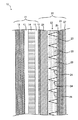
図1は第一実施形態に係る液晶映像源ユニット10の断面を示し、その層構成を模式的に表した図である。本実施形態の液晶映像源ユニット10は、いわゆる液晶ディスプレイパネルユニットである。以下に示す図では、見易さのため、繰り返しとなる符号は一部省略することがある。
FIG. 1 is a cross-sectional view of a liquid crystal
液晶映像源ユニット10は、映像源11と、該映像源11の映像出射側に積層される光拡散シート20とを備えている。映像源11は、バックライト12、偏光板13、液晶パネル14、偏光板15、及び粘着剤層16を有している。また光拡散シート20は、PETフィルム層21、光学機能シート層22、粘着剤層25、TACフィルム層26、及びアンチグレアフィルム層(AG層)27を備えている。図1からわかるように、液晶映像源ユニット10は、映像源11に光拡散シート20が積層されて形成されている。また、液晶映像源ユニット10の上記構成から、当該液晶映像源ユニット10が液晶表示装置に具備されたときには、図1の紙面右側が観察者側となることがわかる。上記各層は図1で示した断面を維持して紙面奥/手前方向に延在する。以下に各層について説明する。
The liquid crystal
バックライト12は、液晶パネル14の光源である。ここには通常の液晶ディスプレイパネルユニットに用いられるバックライトを用いることができる。これには例えば、発光源を面内に略均等に配置して面状の光源とする形式や、縁(エッジ)に発光源を配置して反射面等を利用して最終的に面状に光を出射するエッジ入力型とする形式等を挙げることができる。
The
偏光板13、15は、液晶パネル14を挟むように配置される一対の光学要素であり、吸収軸方向に平行な振動面を有する偏光光を吸収する一方、吸収軸方向に直交する振動面を有する偏光光を透過する機能を有する。当該偏光板13、15と液晶パネル14を透過したバックライト11の光が映像光となり観察者側に出射される。
The
液晶パネル14には、ここに出射されるべき映像情報が表されている。ここには通常の液晶ディスプレイパネルユニットに用いられる液晶パネルを用いることができる。
The
粘着剤層16は、粘着剤が配置された層である。粘着剤層16に用いられる粘着剤は光を透過させるとともに、適切に光拡散シート20を映像源11に接着させることができればその材質は特に限定されるものではない。これには、例えばPSA(感圧接着剤、pressure sensitive adhesive)を挙げることができる。その粘着力は例えば数N/25mm〜20N/25mm程度である。
The pressure-
PETフィルム層21は、該PETフィルム層21の一方の面上に光学機能シート層22を形成するためのベースとなる基材層としてのフィルム層で、ポリエチレンテレフタレート(PET)を主成分として形成されている。当該PETフィルム層21はPETを主成分として含有していれば良く、他の樹脂が含まれてもよい。ここで主成分とはPETフィルム層全体に対して50質量%以上を意味する。また、各種添加剤を添加してもよい。一般的な添加剤としては、フェノール系等の酸化防止剤、ラクトン系等の安定剤等を挙げることができる。
The
ここでは基材層としてPETフィルム層を説明したが、必ずしもPETを材料とすることはなく、その他にもポリブチレンテレフタレート樹脂(PBT)、又はポリトリメチレンテレフタレート(PTT)樹脂等の「ポリエステル系樹脂」を用いることができる。本実施形態では、性能に加え、量産性、価格、入手可能性等の観点からポリエチレンテレフタレート(PET)を主成分とする樹脂が好ましい材料であるとして説明した。 Here, the PET film layer has been described as the base material layer, but the material is not necessarily made of PET, and other than the above, “polyester resin such as polybutylene terephthalate resin (PBT) or polytrimethylene terephthalate (PTT) resin Can be used. In the present embodiment, it has been described that a resin mainly composed of polyethylene terephthalate (PET) is a preferable material from the viewpoints of mass productivity, price, availability, etc. in addition to performance.
光学機能シート層22は、シートの厚さ方向断面において略台形であるプリズム部23、23、…と、該プリズム部23、23、…の間に形成される空洞部24、24、…とを備えている。図2に2つの空洞部24、24及びこれに隣接するプリズム部23、23、23に着目した拡大図を示した。図1、図2を参照しつつ光学機能シート層22について説明する。
The optical
プリズム部23、23、…は、PETフィルム層21側が下底、他方の側が上底となるように配置された略台形断面を有する要素である。また、プリズム部23、23、…は、屈折率がNである光透過性樹脂で構成されている。これは紫外線により硬化する特徴を有する例えばエポキシアクリレート、ウレタンアクリレート等により形成されている。Nの大きさは特に限定されることはないが、適用材料の入手性の観点から1.49〜1.56であることが好ましい。また、プリズム部23、23、…の斜辺角度θや、高さ等によっても好ましい値が設定される。後で詳しく説明する。
当該プリズム部23、23、…内を映像光が透過することにより観察者に映像光が提供される。
The
The image light is provided to the observer by transmitting the image light through the
空洞部24、24、…は、プリズム部23、23、…の間に形成される部位である。従って空洞部24、24、…はプリズム部23、23、…の上底側を底辺とし、これに対向する頂点がプリズム部23、23、…の下底側となるような略三角形形状である。空洞部24、24、…は、空洞で空気が存する状態にあり、屈折率は1.0である。
The
プリズム部23、23、…及び空洞部24、24、…の屈折率差は、N−1.0となる。このように大きな屈折率差を取ることができるので、後述するようにプリズム部23、23、…において反射可能な光を多くすることができ、広い視野角でのコントラストの反転や色彩の不具合を改善することができる。また、プリズム部23、23、…間を空洞とすることにより、ここに何かを充填するための材料や工程を削減することができる。
The refractive index difference between the
また、図2にθで示したように、プリズム部23、23、…の斜辺はシート面法線に対して所定の角度θを有して傾斜している。当該θの大きさは目的に応じて変更可能であり、特に限定されるものではないが、通常の表示装置の場合、適切に外光及び映像光の反射、吸収をする観点から、5度〜15度であることが好ましい。またこのθは、プリズム部23、23、…の屈折率Nや該プリズム部23、23、…の形状によっても好ましい範囲が規定される。これについては後で詳しく説明する。
2, the oblique sides of the
光学機能シート層22は、図1、図2に示したように、プリズム部23、23、…が略台形断面を有し、これらに挟まれて形成される空洞部24、24、…は三角形断面を有している。しかし、適切に光を制御することができれば、これら形状は特に限定されることなく適宜適切な形状が採用される。これには例えば図3(a)に示したように空洞部が三角形断面ではなく、台形断面であってもよい。また、プリズム部の斜辺が図3(b)、図3(c)に示すように折れ線状や曲線状であってもよい。
As shown in FIGS. 1 and 2, the optical
粘着剤層25は、粘着剤が配置された層である。粘着剤層25に用いられる粘着剤は光を透過させるとともに、適切にTACフィルム層26やAG層27等により構成される機能層を光学機能シート層22に接着させることができればその材質は特に限定されるものではない。これには、例えばPSA(感圧接着剤、pressure sensitive adhesive)を挙げることができる。その粘着力は例えば数N/25mm〜20N/25mm程度である。
The pressure-
TACフィルム層26は、トリアセチルセルロースにより形成されるフィルムであり、保護膜として用いられる。また、TACフィルム層26は、光拡散シート20に備えられる機能層を構成する層の1つである。ここに用いられるTACフィルムは通常の液晶映像源ユニットに用いられるものを適用することができる。
The
AG層27は、観察者が画面を見た時のぎらつきを防止(防眩)することができるフィルムである。AG層27も光拡散シート20に備えられる機能層を構成する層の1つである。ここに用いられる防眩フィルムは通常に入手できるものを適用することが可能である。
The
本実施形態では、機能層に備えられる層としてTACフィルム層26及びAG層27を挙げたが、当該機能層に具備される層はこれに限定されるものではない。入射した映像光の質を高めて出射することができる機能を有する層であればこれに含めることができる。これには例えば反射防止層、ハードコート層、帯電防止層、偏光フィルタ層、防汚層等を挙げることができる。
反射防止層はいわゆるアンチリフレクション層であり、AR層ともいわれる。これは反射を防止することができる機能を有するフィルムが配置される。
ハードコート層は、HC層ともいわれる。これは、画像表示面に傷がつくことを抑えるために耐擦傷性を付与することができる機能を有するフィルムが配置された層である。
帯電防止層は、アンチスタティック(AS)層ともいわれる。これは、帯電、すなわち静電気が帯電することを防止することができる機能を有するフィルムが配置された層である。これには通常に入手できるASフィルムを適用することが可能である。
防汚層は画面表面の汚れを防止することができる機能を有するフィルムが配置された層である。
偏光フィルタ層は、上記した偏光フィルタと同様のものである。必要に応じてここに配置してもよい。
In the present embodiment, the
The antireflection layer is a so-called anti-reflection layer and is also referred to as an AR layer. A film having a function capable of preventing reflection is disposed.
The hard coat layer is also called an HC layer. This is a layer in which a film having a function capable of imparting scratch resistance is provided in order to prevent the image display surface from being scratched.
The antistatic layer is also referred to as an antistatic (AS) layer. This is a layer in which a film having a function capable of preventing charging, that is, preventing static electricity from being charged, is disposed. A commonly available AS film can be applied to this.
The antifouling layer is a layer in which a film having a function capable of preventing the screen surface from being stained is disposed.
The polarizing filter layer is the same as the polarizing filter described above. You may arrange here as needed.
以上のような液晶映像源ユニット10を備えることにより液晶表示装置を構成することができる。
By providing the liquid crystal
次に液晶映像源ユニット10が液晶表示装置に備えられ、該液晶表示装置が作動したときの光路について説明する。図2にはその時の光路例(L1、L2、L3)も合わせて示している。図2において、光L1〜L3の光路は模式的に示されたものである。いま、図2において、映像源側(紙面左側)からプリズム部23の中央部付近に入射した垂直光L1は、そのまま光拡散シート20の内部を直進して通過し、観察者に至る。映像源側からプリズム部23の端部付近に入射した垂直光L2は、プリズム部23と空洞部24との屈折率差により斜辺にて全反射され、所定の角度をもって観察者側に出光される。映像源側からプリズム部23端部付近に角度をもって入射した光L3は、斜辺にて全反射され、入射時とは反対方向にさらに大きな角度をもって観察者側に出光される。
Next, the optical path when the liquid crystal
本実施形態の光学機能シート層22は、プリズム部23と空洞部24との屈折率差が大きいので、全反射することのできる映像光が多く、広い視野角域に適切な映像を提供することができる。従って、かかる広い視野角域におけるコントラストの反転や色彩の劣化を改善することができる。
Since the optical
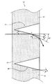
次に図4を参照しつつ光拡散シート20のプリズム部23に入射した光拡散シート20内の光が斜辺にて全反射され、かつ出光面においては、全反射されずに観察者側に透過する条件について説明する。
Next, referring to FIG. 4, the light in the
図4は、光拡散シート20においてプリズム部23の斜辺に垂直光L5が入射した場合の光路を示す図である。図4においては、映像源は図面左方に、観察者は図面右方に位置している。
FIG. 4 is a diagram illustrating an optical path when the vertical light L5 is incident on the oblique side of the
図4において、プリズム部23の斜辺に入射した垂直光L5が、該斜辺のA点において全反射され始める条件(臨界条件)は、スネルの法則により、
sin(90°−θ)=1/N
であるから、垂直光L5が常に全反射されるためには、
(式1) N・sin(90°−θ)>1
なる条件を満たす必要がある。
In FIG. 4, the condition (critical condition) where the vertical light L5 incident on the hypotenuse of the
sin (90 ° −θ) = 1 / N
Therefore, in order that the vertical light L5 is always totally reflected,
(Formula 1) N · sin (90 ° −θ)> 1
It is necessary to satisfy the condition.
また、斜辺のA点にて反射された光L5が、出光面のB点において全反射され始める条件(臨界条件)は、大気の屈折率を1とした場合、スネルの法則により、
sin2θ=1/N
であるから、光L15がB点から観察者側に確実に出光されるためには、
(式2) N<1/sin2θ
なる条件を満たす必要がある。
Further, the condition (critical condition) where the light L5 reflected at the point A on the oblique side starts to be totally reflected at the point B on the light exit surface is as follows according to Snell's law when the refractive index of the atmosphere is 1.
sin2θ = 1 / N
Therefore, in order for the light L15 to be reliably emitted from the point B to the observer side,
(Formula 2) N <1 / sin2θ
It is necessary to satisfy the condition.
以上より、プリズム部斜辺角度θと屈折率Nとが上記関係を有するものとすれば、斜辺で全反射をさせつつ、これを観察者に出光させることができ、効率のよく広い視野角域に適切な映像を提供することが可能となる。そして、かかる広い視野角域におけるコントラストの反転や色彩の劣化を改善することができる。 As described above, if the oblique side angle θ of the prism portion and the refractive index N have the above relationship, it is possible to cause the observer to emit light while performing total reflection on the oblique side, and to efficiently produce a wide viewing angle region. Appropriate video can be provided. Then, it is possible to improve contrast inversion and color degradation in such a wide viewing angle region.
1つの例として図5を参照しつつ、光拡散シート20のプリズム部23の斜辺にシート面法線に対して10°の傾きを持った光L6が入射した場合の光路について以下に簡単に説明する。
As an example, referring to FIG. 5, the optical path when light L6 having an inclination of 10 ° with respect to the normal to the sheet surface is incident on the oblique side of the
図5において、斜辺に入射した10°の傾きを持つ光L6が、斜辺のC点において全反射され始める条件(臨界条件)は、スネルの法則により、
sin(80°−θ)=1/N
であるから、10°の傾きを持った光L6が常に全反射されるためには、
(式3) N・sin(80°−θ)>1
なる条件を満たす必要がある。
In FIG. 5, the condition (critical condition) at which the light L6 having an inclination of 10 ° incident on the hypotenuse starts to be totally reflected at point C of the hypotenuse is Snell's law.
sin (80 ° −θ) = 1 / N
Therefore, in order for the light L6 having an inclination of 10 ° to be always totally reflected,
(Formula 3) N · sin (80 ° −θ)> 1
It is necessary to satisfy the condition.
また、斜辺のC点にて反射された光L6が、出光面のD点において全反射され始める条件(臨界条件)は、大気の屈折率を1とした場合、スネルの法則により、
sin(2θ+10°)=1/N
であるから、光L6がD点から観察者側に確実に出光されるためには、
sin(2θ+10°)<1/N
すなわち
(式4) N<1/sin(2θ+10°)
なる条件を満たす必要がある。
In addition, the condition (critical condition) where the light L6 reflected at the point C on the oblique side starts to be totally reflected at the point D on the light-emitting surface is as follows according to Snell's law when the refractive index of the atmosphere is 1.
sin (2θ + 10 °) = 1 / N
Therefore, in order for the light L6 to be reliably emitted from the point D to the observer side,
sin (2θ + 10 °) <1 / N
That is, (Equation 4) N <1 / sin (2θ + 10 °)
It is necessary to satisfy the condition.
次に、図6を参照しつつ光拡散シート20のプリズム部23の斜辺にて反射された光が、隣接する斜辺に到達しない条件について説明する。この条件を見出すためには、出光面法線に対して最も大きな角度を持つ入射光L7が、空洞部24の三角形である頂点付近の斜辺上の点Eにて全反射された場合に、その反射光が隣接する斜辺に到達しないように、三角形の高さHとプリズム部23上底の長さTとの関係を定める必要がある。
本実施形態では上記最も大きな角度を10°として算出する。
Next, with reference to FIG. 6, a description will be given of a condition in which light reflected by the oblique side of the
In the present embodiment, the largest angle is calculated as 10 °.
図6において、空洞部24の三角形の底辺の長さを2Sとすれば、
tanθ=S/H
tan(2θ+10°)=(S+T)/H
である。したがって、
H=T/(tan(2θ+10°)−tanθ)
となり、Hが上記値より小であれば、反射光が隣接する斜辺に到達しない。したがってその条件は、
H<T/(tan(2θ+10°)−tanθ)
で表される。Hが0以下となることはないので、
(式5) 0<H<T/(tan(2θ+10°)−tanθ)
となる。
In FIG. 6, if the length of the base of the triangle of the
tan θ = S / H
tan (2θ + 10 °) = (S + T) / H
It is. Therefore,
H = T / (tan (2θ + 10 °) −tan θ)
If H is smaller than the above value, the reflected light does not reach the adjacent hypotenuse. Therefore, the condition is
H <T / (tan (2θ + 10 °) −tan θ)
It is represented by Since H is never less than 0,
(Formula 5) 0 <H <T / (tan (2θ + 10 °) −tan θ)
It becomes.
プリズム部、空洞部、において上記の条件を満たすものとすればさらに確実に映像を拡散して観察者に出射することが可能となり、広い視野角域におけるコントラストの反転や色彩の劣化を改善することができる。 If the above conditions are satisfied in the prism part and the cavity part, the image can be more reliably diffused and emitted to the observer, and contrast inversion and color deterioration in a wide viewing angle region can be improved. Can do.
光拡散シート20は例えば次のように製造される。PETフィルムの一面側に、プリズム部の材料となる液状体を塗布する。次に、プリズム部形状を形成するロール金型とPETフィルムとの間に、上記プリズム部となる材料を挟んだ状態で紫外線を照射することにより硬化させてプリズム部23、23、…を形成する。ここでプリズム部形状を形成するロール金型は、その金型表面に空洞部を反転させた形状が形成されているので、当該ロール金型により自動に空洞部が形成される。これにより光学機能シート層22が製造される。このように製造された光学機能シート層22に上記粘着剤層25、TACフィルム層26、及びAG層27が積層される。
For example, the
このように、光拡散シート20は、空洞部を容易に形成することができ、その工程も少なくできることから、コストの観点からも優れた光拡散シート、液晶映像源ユニット、及び液晶表示装置を提供することができる。
As described above, the
図7は第二実施形態に係る液晶映像源ユニット10’の断面を示し、その層構成を模式的に表した図である。液晶映像源ユニット10’は、上記した映像源ユニット10の光学機能シート層22と粘着剤層25との間に、もう1つの光学機能シート層22’が積層されている。光学機能シート層22’は、光学機能シート層22と同様の構成を有しているが、該光学機能シート層22’の光吸収部(図7には、プリズム部23’のみが現れ、光吸収部は現れない。)が光学機能シート層22の光吸収部24、24、…と直交するような向きで配置されている。これにより映像光が拡散される方向が拡張され、さらに広い範囲に光を拡散させることが可能となる。
FIG. 7 is a cross-sectional view of the liquid crystal
図8は、第三実施形態に係る液晶映像源ユニットの光拡散シートのうち、光学機能シート層31の構成を模式的に示した正面図である。図8では、分かりやすさのため正面図の上と右にそれぞれ端面図を示している。光学機能シート層31以外の構成は上記した映像源ユニット10の構成と共通するので、ここでは説明を省略する。また図8の正面図において紙面手前が観察者側、紙面奥が映像源側である。
FIG. 8 is a front view schematically showing the configuration of the optical
図8に示した光学機能シート層31では、断面が三角形である空洞部33a、33a、…、33b、33b、…が格子状に形成され、格子により囲まれた各領域がプリズム部32、32、…となっている。
In the optical
ここでは空洞部33a、33a、…、33b、33b、…断面が三角形であるとしたが、ここが台形であってもよい。この時には台形の短い上底が光源側に、台形の長い下底が観察者側になるように配置される。
Here, the
第三実施形態では、このように一枚の光学機能シート層31の中で空洞部33a、33a、…、33b、33b、…が格子状に形成されている。そして当該格子状は略直角に交わっているのが特徴である。このように形成することにより、1枚の光学機能シート層31で水平、及び垂直方向に視野角を広げることができる。従って、光学シートの厚さを薄くしつつ、あらゆる方向に視野角を広げることが可能となる。
In the third embodiment, the
図9は、第四実施形態に係る液晶映像源ユニットに備えられる光拡散シートのうち、光学機能シート層36の構成を模式的に示した正面図である。図9では、分かりやすさのため正面図の右に端面図を示している。光学機能シート層36以外の構成は上記した光学シート20の構成と共通するので、ここでは説明を省略する。また図9の正面図において紙面手前が観察者側、紙面奥が光源側である。
FIG. 9 is a front view schematically showing the configuration of the optical function sheet layer 36 in the light diffusion sheet provided in the liquid crystal image source unit according to the fourth embodiment. In FIG. 9, an end view is shown on the right side of the front view for easy understanding. Since the configuration other than the optical function sheet layer 36 is the same as the configuration of the
図9に示した光学機能シート層36では、断面が三角形である空洞部38a、38a、…、38b、38b、…が格子状に形成され、格子により囲まれた各領域がプリズム部37、37、…となっている。
In the optical functional sheet layer 36 shown in FIG. 9,
ここでは空洞部38a、38a、…、38b、38b、…断面が三角形であるとしたが、ここが台形であってもよい。この時には台形の短い上底が光源側に、台形の長い下底が観察者側になるように配置される。
Here, the
第四実施形態でも、一枚の光学機能シート層の中で光吸収部が格子状に形成されている。そして当該格子状は所定の角度αを有して交わっているのが特徴である。このように形成することにより、当該αに対応する所定の角度への視野角特性を向上させることができる。 Also in the fourth embodiment, the light absorbing portion is formed in a lattice shape in one optical function sheet layer. The lattice shape intersects with a predetermined angle α. By forming in this way, the viewing angle characteristic to the predetermined angle corresponding to the α can be improved.
図10は第五実施形態に係る液晶映像源ユニット40の断面を示し、その層構成を模式的に表した図である。液晶映像源ユニット40は、上記した映像源ユニット10の映像源11の構成に対し、さらにバックライト12と偏光板13との間に、ルーバー層41が積層された映像源11’を備えている。ルーバー層41はシート面に沿って、光を透過可能に形成された光透過部42、42、…と、光を吸収可能に形成された光吸収部43、43、…とが交互に並列されている。光透過部、及び光吸収部はいずれも断面が矩形に形成されている。これにより、バックライト12から出射される光を平行なものに近付けることができ、効率よく映像を出射することができる。
FIG. 10 is a diagram schematically showing the layer structure of the liquid crystal
以上、現時点において最も実践的であり、かつ好ましいと思われる実施形態に関連して本発明を説明したが、本発明は、本願明細書中に開示された実施形態に限定されるものではなく、請求の範囲及び明細書全体から読み取れる発明の要旨或いは思想に反しない範囲で適宜変更可能であり、そのような変更を伴う光拡散シート及び液晶映像源ユニット、及び液晶表示装置も本発明の技術的範囲に包含されるものとして理解されなければならない。 Although the present invention has been described in connection with the most practical and preferred embodiments at the present time, the present invention is not limited to the embodiments disclosed herein, The invention can be changed as appropriate without departing from the scope or spirit of the invention that can be read from the claims and the entire specification, and the light diffusion sheet, the liquid crystal image source unit, and the liquid crystal display device with such a change are also technical in the present invention. It should be understood as encompassed by the scope.
10、40 液晶映像源ユニット
11 映像源
12 バックライト
13、15 偏光板
14 液晶パネル
16 粘着剤層
20 光拡散シート
21 PETフィルム層
22 光学機能シート層
23 プリズム部
24 空洞部
25 粘着剤層
26 TACフィルム層(機能層)
27 AG層(機能層)
41 ルーバー層
DESCRIPTION OF
27 AG layer (functional layer)
41 louver layer
Claims (8)
前記プリズム部はその断面形状が略台形であり、前記台形の下底を入光部、上底を出光部とするとともに、所定の屈折率Nを有する材料にて形成されており、
隣接する前記プリズム部の間の断面形状三角形の部分は空洞部とされ、
前記台形斜辺が前記出光部の法線となす角度をθとした場合、
N・sin(90°−θ)>1
かつ
N<1/sin2θ
なる関係を有することを特徴とする光拡散シート。 A light diffusion sheet in which a plurality of prism portions are formed in a one-dimensional or two-dimensional direction,
The prism portion has a substantially trapezoidal cross-sectional shape, and is formed of a material having a predetermined refractive index N, with the lower base of the trapezoid as a light entrance portion and the upper base as a light exit portion,
The section of the triangular shape between the adjacent prism parts is a hollow part,
When the angle formed by the trapezoid hypotenuse and the normal line of the light emitting part is θ,
N · sin (90 ° −θ)> 1
And N <1 / sin2θ
A light diffusing sheet characterized by having the following relationship:
前記プリズム部はその断面形状が略台形であり、前記台形の下底を入光部、上底を出光部とするとともに、所定の屈折率Nを有する材料にて形成されており、
隣接する前記プリズム部の間の断面形状三角形の部分は空洞部とされ、
前記台形の上底の長さをT、前記空洞部の高さをH、前記台形斜辺が前記出光部の法線となす角度をθ、とした場合、
0<H<T/(tan(2θ+10°)−tanθ)
なる関係を有することを特徴とする光拡散シート。 A light diffusion sheet in which a plurality of prism portions are formed in a one-dimensional or two-dimensional direction,
The prism portion has a substantially trapezoidal cross-sectional shape, and is formed of a material having a predetermined refractive index N, with the lower base of the trapezoid as a light entrance portion and the upper base as a light exit portion,
The section of the triangular shape between the adjacent prism parts is a hollow part,
When the length of the upper base of the trapezoid is T, the height of the hollow portion is H, and the angle between the trapezoid hypotenuse and the normal line of the light emitting portion is θ,
0 <H <T / (tan (2θ + 10 °) −tanθ)
A light diffusing sheet characterized by having the following relationship:
前記プリズム部はその断面形状が略台形であり、前記台形の下底を入光部、上底を出光部とするとともに、所定の屈折率Nを有する材料にて形成されており、
隣接する前記プリズム部の間の断面形状三角形の部分は空洞部とされ、
前記台形の上底の長さをT、前記空洞部の高さをH、前記台形斜辺が前記出光部の法線となす角度をθ、とした場合、
N・sin(90°−θ)>1
N<1/sin2θ
かつ
0<H<T/(tan(2θ+10°)−tanθ)
なる関係を有することを特徴とする光拡散シート。 A light diffusion sheet in which a plurality of prism portions are formed in a one-dimensional or two-dimensional direction,
The prism portion has a substantially trapezoidal cross-sectional shape, and is formed of a material having a predetermined refractive index N, with the lower base of the trapezoid as a light entrance portion and the upper base as a light exit portion,
The section of the triangular shape between the adjacent prism parts is a hollow part,
When the length of the upper base of the trapezoid is T, the height of the hollow portion is H, and the angle between the trapezoid hypotenuse and the normal line of the light emitting portion is θ,
N · sin (90 ° −θ)> 1
N <1 / sin2θ
And 0 <H <T / (tan (2θ + 10 °) −tanθ)
A light diffusing sheet characterized by having the following relationship:
前記機能層は、反射防止層、ハードコート層、帯電防止層、偏光フィルタ層、防汚層、防眩層、TACフィルム層のうちから選ばれる少なくとも1つの層を含んでいることを特徴とする液晶映像源ユニット。 A liquid crystal image source unit comprising the light diffusion sheet according to any one of claims 1 to 4, wherein a backlight, a liquid crystal panel, the light diffusion sheet, and a functional layer are laminated in this order,
The functional layer includes at least one layer selected from an antireflection layer, a hard coat layer, an antistatic layer, a polarizing filter layer, an antifouling layer, an antiglare layer, and a TAC film layer. LCD image source unit.
Priority Applications (1)
| Application Number | Priority Date | Filing Date | Title |
|---|---|---|---|
| JP2008252915A JP5439786B2 (en) | 2008-09-30 | 2008-09-30 | Light diffusion sheet, liquid crystal image source unit, and liquid crystal display device |
Applications Claiming Priority (1)
| Application Number | Priority Date | Filing Date | Title |
|---|---|---|---|
| JP2008252915A JP5439786B2 (en) | 2008-09-30 | 2008-09-30 | Light diffusion sheet, liquid crystal image source unit, and liquid crystal display device |
Publications (2)
| Publication Number | Publication Date |
|---|---|
| JP2010085586A true JP2010085586A (en) | 2010-04-15 |
| JP5439786B2 JP5439786B2 (en) | 2014-03-12 |
Family
ID=42249621
Family Applications (1)
| Application Number | Title | Priority Date | Filing Date |
|---|---|---|---|
| JP2008252915A Expired - Fee Related JP5439786B2 (en) | 2008-09-30 | 2008-09-30 | Light diffusion sheet, liquid crystal image source unit, and liquid crystal display device |
Country Status (1)
| Country | Link |
|---|---|
| JP (1) | JP5439786B2 (en) |
Cited By (3)
| Publication number | Priority date | Publication date | Assignee | Title |
|---|---|---|---|---|
| JP2012008320A (en) * | 2010-06-24 | 2012-01-12 | Dainippon Printing Co Ltd | Optical sheet, optical sheet roll, method for manufacturing optical sheet, and video display device |
| JP2014106244A (en) * | 2012-11-22 | 2014-06-09 | Dainippon Printing Co Ltd | Optical sheet, surface light source device, and display device |
| JP2014206754A (en) * | 2014-07-14 | 2014-10-30 | 大日本印刷株式会社 | Display apparatus and mobile terminal |
Citations (4)
| Publication number | Priority date | Publication date | Assignee | Title |
|---|---|---|---|---|
| JPH0993518A (en) * | 1995-04-19 | 1997-04-04 | Hitachi Ltd | Transmissive screen and rear side projection type image display device using the same |
| JP2004004148A (en) * | 2001-05-14 | 2004-01-08 | Dainippon Printing Co Ltd | Sheet for projection screen, light diffusion sheet, and the projection screen |
| JP2007250345A (en) * | 2006-03-16 | 2007-09-27 | Sumitomo Chemical Co Ltd | Surface light source device, and liquid crystal display device |
| JP2008151854A (en) * | 2006-12-14 | 2008-07-03 | Dainippon Printing Co Ltd | Optical sheet |
-
2008
- 2008-09-30 JP JP2008252915A patent/JP5439786B2/en not_active Expired - Fee Related
Patent Citations (4)
| Publication number | Priority date | Publication date | Assignee | Title |
|---|---|---|---|---|
| JPH0993518A (en) * | 1995-04-19 | 1997-04-04 | Hitachi Ltd | Transmissive screen and rear side projection type image display device using the same |
| JP2004004148A (en) * | 2001-05-14 | 2004-01-08 | Dainippon Printing Co Ltd | Sheet for projection screen, light diffusion sheet, and the projection screen |
| JP2007250345A (en) * | 2006-03-16 | 2007-09-27 | Sumitomo Chemical Co Ltd | Surface light source device, and liquid crystal display device |
| JP2008151854A (en) * | 2006-12-14 | 2008-07-03 | Dainippon Printing Co Ltd | Optical sheet |
Cited By (3)
| Publication number | Priority date | Publication date | Assignee | Title |
|---|---|---|---|---|
| JP2012008320A (en) * | 2010-06-24 | 2012-01-12 | Dainippon Printing Co Ltd | Optical sheet, optical sheet roll, method for manufacturing optical sheet, and video display device |
| JP2014106244A (en) * | 2012-11-22 | 2014-06-09 | Dainippon Printing Co Ltd | Optical sheet, surface light source device, and display device |
| JP2014206754A (en) * | 2014-07-14 | 2014-10-30 | 大日本印刷株式会社 | Display apparatus and mobile terminal |
Also Published As
| Publication number | Publication date |
|---|---|
| JP5439786B2 (en) | 2014-03-12 |
Similar Documents
| Publication | Publication Date | Title |
|---|---|---|
| JP5633372B2 (en) | Optical sheet and image display device | |
| KR102255145B1 (en) | Semi-transmissive reflective sheet, light guide plate, and display device | |
| JP6717051B2 (en) | Screen, video display | |
| JP6834153B2 (en) | Space floating image display device | |
| JP5277931B2 (en) | Optical sheet and image display device | |
| JP6988069B2 (en) | Reflective screen, video display device | |
| JP5439786B2 (en) | Light diffusion sheet, liquid crystal image source unit, and liquid crystal display device | |
| JP5287147B2 (en) | Optical sheet and image display device | |
| JP6593201B2 (en) | Screen, video display device | |
| WO2012099123A1 (en) | Light guide plate, surface light source device, and transmissive image display device | |
| JP6717052B2 (en) | Reflective screen, video display | |
| JP5327746B2 (en) | Liquid crystal display | |
| JP6747132B2 (en) | Transmissive screen, rear projection display | |
| JP6938872B2 (en) | Video display device | |
| JP5949356B2 (en) | Reflective screen, 3D image display system | |
| JP2018025620A (en) | Transmissive screen and video display device | |
| JP2009294468A (en) | Video display device and optical sheet | |
| JP6812757B2 (en) | Video display device | |
| JP2016151710A (en) | Optical sheet, video source unit, and video display device | |
| JP2015064497A (en) | Linear fresnel lens sheet and transmissive display device | |
| JP6089429B2 (en) | Display device | |
| JP2017198974A (en) | Optical unit, surface light source device, video source unit, and liquid crystal display | |
| JP7226119B2 (en) | Transmissive screen, image display device | |
| JP7322511B2 (en) | Transmissive screen, image display device | |
| JP2013120266A (en) | Optical module and display device |
Legal Events
| Date | Code | Title | Description |
|---|---|---|---|
| RD01 | Notification of change of attorney |
Free format text: JAPANESE INTERMEDIATE CODE: A7421 Effective date: 20101101 |
|
| A621 | Written request for application examination |
Free format text: JAPANESE INTERMEDIATE CODE: A621 Effective date: 20110819 |
|
| A977 | Report on retrieval |
Free format text: JAPANESE INTERMEDIATE CODE: A971007 Effective date: 20120919 |
|
| A131 | Notification of reasons for refusal |
Free format text: JAPANESE INTERMEDIATE CODE: A131 Effective date: 20121002 |
|
| A521 | Written amendment |
Free format text: JAPANESE INTERMEDIATE CODE: A523 Effective date: 20121121 |
|
| A02 | Decision of refusal |
Free format text: JAPANESE INTERMEDIATE CODE: A02 Effective date: 20130709 |
|
| A521 | Written amendment |
Free format text: JAPANESE INTERMEDIATE CODE: A523 Effective date: 20131008 |
|
| A911 | Transfer of reconsideration by examiner before appeal (zenchi) |
Free format text: JAPANESE INTERMEDIATE CODE: A911 Effective date: 20131016 |
|
| TRDD | Decision of grant or rejection written | ||
| A01 | Written decision to grant a patent or to grant a registration (utility model) |
Free format text: JAPANESE INTERMEDIATE CODE: A01 Effective date: 20131119 |
|
| A61 | First payment of annual fees (during grant procedure) |
Free format text: JAPANESE INTERMEDIATE CODE: A61 Effective date: 20131202 |
|
| R150 | Certificate of patent or registration of utility model |
Free format text: JAPANESE INTERMEDIATE CODE: R150 |
|
| LAPS | Cancellation because of no payment of annual fees |