JP2010074214A - Passive optical network system and optical multiplexed terminator - Google Patents
Passive optical network system and optical multiplexed terminator Download PDFInfo
- Publication number
- JP2010074214A JP2010074214A JP2008235982A JP2008235982A JP2010074214A JP 2010074214 A JP2010074214 A JP 2010074214A JP 2008235982 A JP2008235982 A JP 2008235982A JP 2008235982 A JP2008235982 A JP 2008235982A JP 2010074214 A JP2010074214 A JP 2010074214A
- Authority
- JP
- Japan
- Prior art keywords
- signal
- transmission rate
- transmission
- onu
- information
- Prior art date
- Legal status (The legal status is an assumption and is not a legal conclusion. Google has not performed a legal analysis and makes no representation as to the accuracy of the status listed.)
- Granted
Links
Images


Classifications
-
- H—ELECTRICITY
- H04—ELECTRIC COMMUNICATION TECHNIQUE
- H04Q—SELECTING
- H04Q11/00—Selecting arrangements for multiplex systems
- H04Q11/0001—Selecting arrangements for multiplex systems using optical switching
- H04Q11/0062—Network aspects
- H04Q11/0067—Provisions for optical access or distribution networks, e.g. Gigabit Ethernet Passive Optical Network (GE-PON), ATM-based Passive Optical Network (A-PON), PON-Ring
-
- H—ELECTRICITY
- H04—ELECTRIC COMMUNICATION TECHNIQUE
- H04B—TRANSMISSION
- H04B10/00—Transmission systems employing electromagnetic waves other than radio-waves, e.g. infrared, visible or ultraviolet light, or employing corpuscular radiation, e.g. quantum communication
- H04B10/70—Photonic quantum communication
-
- H—ELECTRICITY
- H04—ELECTRIC COMMUNICATION TECHNIQUE
- H04J—MULTIPLEX COMMUNICATION
- H04J3/00—Time-division multiplex systems
- H04J3/02—Details
- H04J3/06—Synchronising arrangements
- H04J3/0635—Clock or time synchronisation in a network
- H04J3/0682—Clock or time synchronisation in a network by delay compensation, e.g. by compensation of propagation delay or variations thereof, by ranging
-
- H—ELECTRICITY
- H04—ELECTRIC COMMUNICATION TECHNIQUE
- H04J—MULTIPLEX COMMUNICATION
- H04J3/00—Time-division multiplex systems
- H04J3/02—Details
- H04J3/06—Synchronising arrangements
- H04J3/0635—Clock or time synchronisation in a network
- H04J3/0638—Clock or time synchronisation among nodes; Internode synchronisation
- H04J3/0652—Synchronisation among time division multiple access [TDMA] nodes, e.g. time triggered protocol [TTP]
-
- H—ELECTRICITY
- H04—ELECTRIC COMMUNICATION TECHNIQUE
- H04Q—SELECTING
- H04Q11/00—Selecting arrangements for multiplex systems
- H04Q11/0001—Selecting arrangements for multiplex systems using optical switching
- H04Q11/0062—Network aspects
- H04Q2011/0064—Arbitration, scheduling or medium access control aspects
-
- H—ELECTRICITY
- H04—ELECTRIC COMMUNICATION TECHNIQUE
- H04Q—SELECTING
- H04Q11/00—Selecting arrangements for multiplex systems
- H04Q11/0001—Selecting arrangements for multiplex systems using optical switching
- H04Q11/0062—Network aspects
- H04Q2011/0079—Operation or maintenance aspects
Landscapes
- Engineering & Computer Science (AREA)
- Computer Networks & Wireless Communication (AREA)
- Signal Processing (AREA)
- Physics & Mathematics (AREA)
- Optics & Photonics (AREA)
- Electromagnetism (AREA)
- Small-Scale Networks (AREA)
- Optical Communication System (AREA)
Abstract
Description
本発明は、受動光網システム及び光多重終端装置に係り、特に、複数の加入者接続装置が光伝送回線を共有する受動光網システム及び光多重終端装置に関する。 The present invention relates to a passive optical network system and an optical multiple termination device, and more particularly to a passive optical network system and an optical multiple termination device in which a plurality of subscriber connection devices share an optical transmission line.
大容量の画像信号やデータを通信網を介して送受信する為に、通信網の高速・広帯域化が加入者を通信網へ接続するアクセス網でも進められ、国際電気通信連合(以下ITU−Tと称す)の勧告G.984.1−3等で規定された光受動網システム(Passive Optical Network system:以下PONと称する)の導入が図られている。PONは、上位の通信網と接続される光多重終端装置(Optical Line Terminator:以下OLTと称する)と、複数の加入者の端末(PCや電話)を収容する光網終端装置(Optical Network Unit:以下ONUと称する)とを、基幹光ファイバと光スプリッタと複数の支線光ファイバとを有する光受動網で接続したシステムである。具体的には、各ONUに接続された端末(PC他)からの信号を光信号で支線光ファイバから光スプリッタを介して基幹光ファイバで光学(時分割)多重してOLTに送り、OLTが各ONUからの信号を通信処理して上位の通信網に送信する、あるいは、OLTに接続される他のONUに送信するという形態で通信を行うものである。 In order to transmit and receive large-capacity image signals and data via a communication network, the speed and bandwidth of the communication network has been increased in the access network connecting subscribers to the communication network. Recommendation G. An optical passive network system (Passive Optical Network system: hereinafter referred to as PON) defined in 984.1-3 and the like is being introduced. The PON is an optical multiple terminator (hereinafter referred to as OLT) connected to a host communication network and an optical network terminator (Optical Network Unit) that accommodates a plurality of subscriber terminals (PCs and telephones). (Hereinafter referred to as ONU) is connected by an optical passive network having a backbone optical fiber, an optical splitter, and a plurality of branch optical fibers. Specifically, signals from terminals (PCs, etc.) connected to each ONU are optically (time-division-multiplexed) from the branch optical fiber via the optical splitter via the optical fiber splitter (time division) and sent to the OLT. Communication is performed in a form in which signals from each ONU are processed and transmitted to a higher-level communication network, or transmitted to other ONUs connected to the OLT.
PONの開発・導入は64kbit/秒のような低速信号を扱うシステムから始まり、固定長のATMセルを最大約600Mbit/秒で送受信するBPON(Broadband PON)、イーサネット(登録商標)の可変長パケットを最大約1Gbit/秒で送受信するイーサネット(登録商標)PON(EPON)や、より高速な2.4Gbit/秒程度の信号を扱うITU−T勧告G.984.1、G.984.2およびG.984.3で標準化されたGPON(Gigabit PON)の導入が進められている。更に、今後は10Gbit/秒から40Gbit/秒の信号を扱うことが可能な高速PONの実現が求められている。これらの高速PONを実現する手段としては、多数の信号を時分割多重するTDM(Time Division Multiplexing)、波長多重するWDM(Wavelength Division Multiplexing)多重、符号多重するCDM(Code Division Multiplexing)多重等の多重化方法が検討されている。尚、現状のPONはTDMを採用しており、例えば、GPONは、上り(ONUからOLT)の信号と下り(OLTからONU)の信号とで異なる波長を用い、OLTと各ONU間の通信は、各ONUに対して信号の通信時間を割り当てる構成である。また、従来の固定長信号を処理する構成から、より多様な種別の信号(音声、画像、データ等)を扱い易いバースト状の可変長信号(バースト信号)も処理する構成になってきている。今後の高速PONも、上述したように様々な多重化方法が検討されているが、TDMを採用する方向での検討が主になりつつある。
上記各PONの形態では、様々な場所に点在する加入者宅にONUを設置するためOLTからONUまでの距離が異なる。すなわち、OLTから各ONU迄の基幹光ファイバと支線光ファイバを合わせた光ファイバの長さ(伝送距離)がばらつくため、各ONUとOLT間の伝送遅延がばらつく。各ONUが異なるタイミングで信号を送信しても、基幹光ファイバ上で各ONUから出力される光信号同士が衝突・干渉する可能性がある。このため、各PONにおいては、例えばG.984.3の10章で規定したような、レンジングと称される技術を用いて、OLTとONUとの間の距離測定を行った後に、各ONUからの信号出力が衝突しないように各ONUの出力信号の遅延を調整するようにしている。
Development and introduction of PON begins with a system that handles low-speed signals such as 64 kbit / sec. BPON (Broadband PON) and Ethernet (registered trademark) variable-length packets that transmit and receive fixed-length ATM cells at a maximum of approximately 600 Mbit / sec. Ethernet (registered trademark) PON (EPON) that transmits and receives at a maximum of about 1 Gbit / sec, and ITU-T recommendation G.2 that handles higher-speed signals of about 2.4 Gbit / sec. 984.1, G.A. 984.2 and G.A. Introduction of GPON (Gigabit PON) standardized in 984.3 is underway. Furthermore, in the future, it is required to realize a high-speed PON capable of handling signals of 10 Gbit / second to 40 Gbit / second. Means for realizing these high-speed PONs include TDM (Time Division Multiplexing) for time-division multiplexing of a large number of signals, WDM (Wavelength Division Multiplexing) multiplexing for wavelength multiplexing, and CDM (Code Division Multiplexing) multiplexing for code multiplexing. The method of making it is being studied. The current PON employs TDM. For example, GPON uses different wavelengths for upstream (ONU to OLT) and downstream (OLT to ONU) signals, and communication between the OLT and each ONU is performed. In this configuration, a signal communication time is assigned to each ONU. Further, the conventional configuration for processing fixed-length signals has been configured to process burst-like variable-length signals (burst signals) that can easily handle various types of signals (sound, image, data, etc.). As for the future high-speed PON, as described above, various multiplexing methods have been studied, but studies in the direction of adopting TDM are becoming main.
In each of the above PON forms, the distance from the OLT to the ONU is different because the ONUs are installed at subscriber homes scattered in various places. That is, since the length (transmission distance) of the optical fiber including the backbone optical fiber and the branch optical fiber from the OLT to each ONU varies, the transmission delay between each ONU and the OLT varies. Even if the respective ONUs transmit signals at different timings, there is a possibility that optical signals output from the respective ONUs collide and interfere with each other on the backbone optical fiber. For this reason, in each PON, for example, G.M. After measuring the distance between the OLT and the ONU using a technique called ranging as defined in
更に、OLTは、動的帯域割り当て(Dynamic Bandwidth Assignment:以下DBAと称する)と称される技術を用いて各ONUからの送信要求に基づき該ONUに送信を許可する信号の帯域を決めると、上述したレンジングで測定した遅延量も考慮した上で、各ONUからの光信号が基幹光ファイバ上で衝突・干渉しないように各ONUへ送信タイミングを指定するようにしている。すなわち、PONは、OLTと各ONU間で送受信される信号のタイミングがシステム内で管理された状態で通信の運用がなされるように構成されている。
OLTと各ONU間との信号の送受信においては、例えばG.984.2の8.3.3章の規定によれば、OLTが基幹光ファイバで多重された各ONUからの信号を識別して処理できるように、各ONUからの信号の先頭に最大12バイトからなる干渉防止用のガードタイム、OLT内受信器の信号識別閾値の決定およびクロック抽出に利用するプリアンブル、受信信号の区切りを識別するデリミタと呼ばれるバーストオーバヘッドバイトとPONの制御信号(オーバヘッドあるいはヘッダと称することもある)がデータ(ペイロードと称することもある)に付加される。尚、各データは可変長のバーストデータであるため、各データの先頭には、可変長データを処理するためのGEM(G−PON Encapsulation Method)ヘッダと呼ばれるヘッダも付加される。また、OLTから各ONU宛の信号には、各ONUがOLTからの信号を識別して処理できるように、OLTから各ONUに向けて送信される信号の先頭に、先頭を識別するためのフレーム同期パタン、監視・保守・制御情報を送信するPLOAM領域、各ONUの信号送信タイミングを指示するグラント指示領域と呼ばれるオーバヘッド(ヘッダと称されることもある)が各ONU宛に時分割多重化されたデータに付加される構成である。尚、多重化される各ONU宛のデータには、ONUからの信号と同様に、可変長データを処理するためのGEMヘッダが付加されている。OLTは、グラント指示領域を用いて各ONUの上り送信許可タイミング(送信開始(Start)と終了(Stop))を各ONUにバイト単位で指定する。この送信許可タイミングをグラントと称している。そして、各ONUが該許可タイミングでOLT宛のデータを送信すると、これらが光ファイバー上で光学(時分割)多重されOLTで受信される。
Further, when the OLT determines a band of a signal that is permitted to be transmitted to each ONU based on a transmission request from each ONU using a technique called dynamic bandwidth assignment (hereinafter referred to as DBA), the above-described operation is performed. Considering the delay amount measured by the ranging, the transmission timing is designated to each ONU so that the optical signal from each ONU does not collide or interfere on the backbone optical fiber. That is, the PON is configured such that communication is performed in a state where the timing of signals transmitted and received between the OLT and each ONU is managed in the system.
In signal transmission / reception between the OLT and each ONU, for example, G. According to the provisions in Chapter 8.3.2 of 984.2, the maximum length of 12 bytes at the beginning of the signal from each ONU is such that the OLT can identify and process the signal from each ONU multiplexed on the backbone optical fiber. A guard time for preventing interference, determination of a signal identification threshold of the receiver in the OLT, preamble used for clock extraction, burst overhead byte called delimiter for identifying a received signal delimiter, and PON control signal (overhead or header) Is appended to the data (sometimes referred to as the payload). Since each data is variable-length burst data, a header called a GEM (G-PON Encapsulation Method) header for processing variable-length data is also added to the head of each data. In addition, a frame for identifying the head of the signal transmitted from the OLT to each ONU is included in the signal addressed to each ONU from the OLT so that each ONU can identify and process the signal from the OLT. Overhead (sometimes called a header) called synchronization pattern, PLOAM area for transmitting monitoring / maintenance / control information, and grant indication area for instructing signal transmission timing of each ONU is time-division multiplexed to each ONU. It is a configuration added to the data. Note that a GEM header for processing variable-length data is added to the data addressed to each ONU to be multiplexed, similarly to the signal from the ONU. The OLT specifies the upstream transmission permission timing (transmission start (Start) and end (Stop)) of each ONU in units of bytes using the grant indication area. This transmission permission timing is called a grant. When each ONU transmits data addressed to the OLT at the permission timing, these are optically (time-division) multiplexed on the optical fiber and received by the OLT.
PONでは、OLTから複数のONUへの信号が時分割多重されて全ONUへ伝送される。すなわち、各ONUは、ONUに提供される信号の帯域(信号量)が小さくとも、OLTから各ONUへの通信信号の全てを一旦受信し、自ONU宛の通信内容をヘッダ(具体的には、GPONならGEMヘッダのPORT ID、EPONならLLIDと称されるONUの識別子)を用いて識別して、識別された信号だけをONU内部に取り込んで加入者(ユーザ)の装置に転送している。上述したように、PONは、BPONからGPONへの移行のように、低速信号を処理するものから、より高速信号を処理するものへと開発・導入が進んできている。しかし、各PONとも標準化が進み、信号の伝送速度や制御信号のやり取り・プロトコルは古いPONも吸収するように配慮はされているが完全に互換性を有する形ではなく、PON毎に異なった形で決まってきているのが現状である。このため、通信サービス容量の拡大によりONUが従来技術で対応している伝送速度以上の速度をサポートする必要が生じた時は、BPONをGPONに入れ替えるというように、PON全体の伝送速度を拡大した新しいPONを採用(入れ替え)する必要がある。すなわち、OLTおよびOLTに接続される全てのONUを新しく伝送容量を拡大したPONに合わせて新しい設備に交換する必要がある。 In PON, signals from the OLT to a plurality of ONUs are time-division multiplexed and transmitted to all ONUs. That is, each ONU once receives all communication signals from the OLT to each ONU even if the band (signal amount) of the signal provided to the ONU is small, and the communication contents addressed to the own ONU are sent to the header (specifically, In the case of GPON, the ID is identified using the PORT ID in the GEM header, and in the case of EPON, the identifier of the ONU called LLID), and only the identified signal is taken into the ONU and transferred to the subscriber (user) device. . As described above, PON has been developed and introduced from one that processes low-speed signals to one that processes higher-speed signals, as in the transition from BPON to GPON. However, standardization has progressed for each PON, and signal transmission speed and control signal exchange / protocol are considered to absorb old PON, but not completely compatible, but different for each PON. The current situation has been decided. For this reason, when it becomes necessary to support a transmission rate higher than the transmission rate supported by the conventional technology due to the expansion of communication service capacity, the transmission rate of the entire PON has been expanded, such as replacing BPON with GPON. It is necessary to adopt (replace) a new PON. In other words, it is necessary to replace the OLT and all ONUs connected to the OLT with new equipment in accordance with the PON having a newly increased transmission capacity.
PONの導入や利用形態を考えると、より高速なサービス容量提供のニーズが増えてはいくものの、瞬時にニーズが全て代わるものではなく、一部ユーザでの利用が始まり徐々に増えていくと考えられ、この間は既存のPONでも充分という加入者も多数存在する。既存のPONを新たなPONに交換することは、上述のように、全てのOLTとONUの交換を行うことであり、交換のために多くの費用が必要となる。また、上記通信サービス容量の拡大の実体を考えると、あるユーザにとっては未だ必要の無い設備の交換も行うことにもなり、PONを導入するキャリアやPONを利用するユーザにとって割高な費用負担をもたらすことにもなりかねない。このため、伝送速度の異なるPONの設備を相互接続したり、既存のPONの設備を収容しつつ新しいPONへと移行できるような、規格や性能が異なる複数のPONを混在させて運用出来るような構成のPONとその通信方法が求められる。
ここで高速な信号や低速な信号など、複数の伝送速度のPONを混在する場合、信号送信時には光信号のビットレートの違いによる光レベルの相違が考えられる。このとき、受信側のONUは、入力信号のレベル変動に追随するため数百ナノ秒程度の引き込み時間が一般的に必要である。OLT配下の各ONUは、この入力信号(受信信号)のレベル変動へ追随できなければ、伝送速度切り替え直後から受信信号レベル変動へ追随するまでの一部のデータが受信エラーを起こす場合がある。この課題を解決するためには、伝送速度の切り替えに対応できる高機能な受信機をONU側で採用すればよいが、ONU自体のコストが上昇する課題がある。
Considering the introduction and usage form of PON, although the need for faster service capacity provision will increase, not all the needs will be replaced instantaneously, and the use by some users will start and gradually increase During this time, there are many subscribers who are satisfied with the existing PON. Replacing an existing PON with a new PON means that all OLTs and ONUs are exchanged as described above, and a large amount of cost is required for the exchange. In addition, considering the actual expansion of the communication service capacity, equipment that is not yet necessary for a certain user is also exchanged, resulting in a high cost burden for the carrier that introduces the PON and the user who uses the PON. It can also be a thing. For this reason, PON equipment with different transmission speeds can be interconnected, or multiple PONs with different standards and performance can be mixed and operated so that existing PON equipment can be accommodated and moved to a new PON. A PON with a configuration and its communication method are required.
Here, when a plurality of PONs having a plurality of transmission speeds such as a high-speed signal and a low-speed signal are mixed, a difference in optical level due to a difference in the bit rate of the optical signal can be considered during signal transmission. At this time, the ONU on the receiving side generally needs a pull-in time of about several hundred nanoseconds to follow the level fluctuation of the input signal. If each ONU under the OLT cannot follow the level fluctuation of the input signal (reception signal), a part of data from immediately after the transmission speed switching to the reception signal level fluctuation may cause a reception error. In order to solve this problem, a high-functional receiver that can cope with switching of transmission rates may be employed on the ONU side, but there is a problem that the cost of the ONU itself increases.
本発明は、以上の点に鑑み、伝送速度の異なる複数の仕様(規格)のPONを混在させて運用出来る構成のOLTと、それぞれ1つの伝送速度を送受信できるONUとを有する受動光網システム及び光多重終端装置を提供することを目的とする。より具体的には、本発明は、OLTと各ONUとの信号の通信を時分割多重で行うPONにおいて、信号の伝送速度の異なる複数のONUを混在収容して運用できる構成のOLTとONUを備えた受動光網システム及び光多重終端装置を提供することを目的のひとつとする。また、本発明は、OLTが複数の伝送速度の異なるフレームを混在して送信し、各伝送速度のフレーム切り替え時にONUが受信時において光レベルの変動に伴う受信信号レベルの変動に追随できるようなフレーム構成を用いることを目的のひとつとする。本発明は、各ONUがエラー無く自身が対応可能な伝送速度のフレームを送受信することを可能にすることを目的のひとつとする。
本発明は、通信サービス容量拡大の要求が発生しても対応するOLTおよびONUのみ交換することで、通信装置の交換費用を抑制することを目的のひとつとする。また、本発明は、高速な信号と低速な信号が混在した下り信号を受信するONUにおいて、レベル変動に対して高速応答が可能な高機能な部品を採用する必要が無く、より安価なONUで混在信号を送受信可能とすることを目的のひとつとする。
In view of the above, the present invention provides a passive optical network system having an OLT configured to be able to operate a mixture of PONs having different specifications (standards) having different transmission speeds, and an ONU capable of transmitting and receiving one transmission speed each. An object of the present invention is to provide an optical multiple termination device. More specifically, the present invention relates to an OLT and an ONU configured to accommodate and operate a plurality of ONUs having different signal transmission rates in a PON in which signal communication between the OLT and each ONU is performed by time division multiplexing. An object of the present invention is to provide a passive optical network system and an optical multiple termination device provided. Further, the present invention enables the OLT to transmit a plurality of frames having different transmission rates in a mixed manner so that the ONU can follow the variation in the received signal level accompanying the variation in the optical level at the time of reception when switching the frames at each transmission rate. One of the purposes is to use a frame structure. An object of the present invention is to enable each ONU to transmit and receive a frame having a transmission rate that it can handle without error.
An object of the present invention is to suppress the cost of replacing a communication device by exchanging only the corresponding OLT and ONU even when a request for expanding the communication service capacity occurs. In addition, the present invention eliminates the need to use high-functional parts capable of high-speed response to level fluctuations in an ONU that receives a downstream signal in which high-speed signals and low-speed signals are mixed. One of the purposes is to enable transmission and reception of mixed signals.
PONのOLTと各ONU間で送受信される信号は、上述したような距離に応じて送信タイミングを補正する等の立上げ動作を行った後、サービス状態へ移行する。サービス状態(通常運用時)は、ユーザの要求や契約に応じた高速サービスを提供する。
PONは、上述したレンジングやDBAの技術に基づき信号の送受信タイミングが管理された状態で運用されるものである。したがって、複数の速度のデータが混載していても、それらの位置(送受信タイミング)を把握して処理できる。すなわち、各ONUが自ONUの受信可能な伝送速度の到達タイミングや、自ONU宛のフレームが到達するタイミングが理解できれば、エラーを回避して通信が可能である。
本発明は、上記PONの特性に着目したもので、上記課題を達成するために、信号の伝送速度の異なる複数のONUを混在収容する場合、OLTは各ONUに合った伝送速度のデータの混在したフレームを作製し、各伝送速度の信号間にONUが追随できるような時間を確保するためのダミー信号を配置する構成と、フレーム内に伝送速度毎の信号の到着タイミングを通知する構成を有する。
A signal transmitted and received between the PON OLT and each ONU undergoes a startup operation such as correcting the transmission timing according to the distance as described above, and then shifts to a service state. The service state (during normal operation) provides a high-speed service according to user requests and contracts.
The PON is operated in a state in which signal transmission / reception timing is managed based on the above-described ranging and DBA technologies. Therefore, even if data of a plurality of speeds are mixedly loaded, their positions (transmission / reception timing) can be grasped and processed. That is, if each ONU can understand the arrival timing of the transmission rate at which the ONU can be received and the timing at which the frame addressed to the ONU arrives, communication can be performed while avoiding errors.
The present invention pays attention to the characteristics of the PON, and in order to achieve the above-mentioned problem, when a plurality of ONUs having different signal transmission rates are accommodated together, the OLT is a mixture of data having transmission rates suitable for each ONU. And a configuration for arranging a dummy signal for ensuring a time that the ONU can follow between signals at each transmission rate, and a configuration for notifying the arrival timing of a signal at each transmission rate in the frame. .
具体的には、PONが通常運用に移行する前に、伝送速度毎にレンジングを行い、OLTが配下の各ONUの伝送速度を把握する。このとき、通常運用時の下り信号送信時における伝送速度毎のデータ格納量の閾値(又は割合)を決定する。通常運用時にそれぞれの伝送速度に対応した各ONUへフレームを送信する際は、上位網から転送される各ONU宛のデータと前述で判明した各ONUの伝送速度を照らし合わせ、OLT内で各ONUに合った伝送速度へ変換し、高速と低速が混在したフレームを作製する。このとき、上位網から転送されてくるデータの優先度を判断し、例えば、優先度の高いものから閾値を超えない範囲で、各伝送速度のデータを格納するフレーム構成とする。また、各伝送速度の切り替え時、ONUが伝送速度の変更(光レベルの変動)に伴う受信信号レベルの変動に追随できるようにするため、本来のデータとは関係ないダミー信号を追加する。このダミー信号は本来のデータ伝送には関係無いデータなので、なるべく必要最小限の挿入に留める。このとき構成したフレームの高速な部分と低速な部分のタイミング情報は下りBW(Band Width)マップと称し、各伝送速度のオーバヘッド内に追加して配下の各ONUへ転送される。 Specifically, before the PON shifts to normal operation, ranging is performed for each transmission speed, and the OLT grasps the transmission speed of each ONU under its control. At this time, the threshold (or rate) of the data storage amount for each transmission rate at the time of downlink signal transmission during normal operation is determined. When a frame is transmitted to each ONU corresponding to each transmission speed during normal operation, the data addressed to each ONU transferred from the upper network is compared with the transmission speed of each ONU determined above, and each ONU is within the OLT. The frame is mixed with high speed and low speed. At this time, the priority of the data transferred from the higher level network is determined, and for example, the frame configuration is such that the data of each transmission rate is stored in the range from the higher priority to the threshold not exceeded. In addition, a dummy signal that is not related to the original data is added so that the ONU can follow the fluctuation of the received signal level accompanying the change of the transmission speed (the fluctuation of the optical level) at the time of switching each transmission speed. Since this dummy signal is not related to the original data transmission, it is limited to the minimum necessary insertion. The timing information of the high-speed portion and the low-speed portion of the frame configured at this time is called a downstream BW (Band Width) map, and is added to the overhead of each transmission rate and transferred to each subordinate ONU.
この構成によって各ONUは、異なる伝送速度が混在したフレームが転送された場合でもダミー信号の効果で各伝送速度に追随でき、下りBWマップの通知に基づいて次フレーム到達時に、対応した伝送速度のフレームが到着するタイミング又は、自ONU宛のタイミング毎にエラー無く受信動作が行える。この構成によって、各ONUはエラーを検出することなく、目的のフレームを受信することができる。また、ヘッダに付与したグラント指示に基づいて、OLTが伝送速度の異なる各ONUからの信号の受信時に、伝送速度毎に受信機を切り替えることによって、異なる伝送速度での通信を行う。
本受動光網システムは、例えば、親局と伝送速度の異なる複数の子局とを光スプリッタを含む光ファイバ網で接続した受動光網システムであって、
前記子局は、第1の伝送速度の第1のデータのみを送受信可能な子局と、該第1の伝送速度より高速な第2の伝送速度の第2のデータのみを送受信可能な子局が親局に接続されている受動光網システムであって、
前記親局は、第1の伝送速度の第1のデータと該第1の伝送速度より高速な第2の伝送速度の第2のデータをそれぞれの子局へ送信する際、
通常運用前に各子局の送受信可能な伝送速度情報を把握することができ、データ送信時における各伝送速度の送信量の閾値を決定する調整回路と、(ONU伝送速度情報記憶・閾値決定部)
各子局宛のデータの照会を行う調整回路と、(優先度別キュー情報監視部)
前記複数の伝送速度のデータの間に、前記子局がエラー無く受信可能にするためのダミー信号を組み込む組み込み回路と、(ダミー信号生成部)
前記各子局宛のデータと前記各子局の伝送速度情報を照会し、送信タイミングを調整する調整回路と、(下りBWマップテーブル作成部又は下りBWマップ生成部)
受信したデータを前述したタイミングを基に、適切な伝送速度に変換する組み立て回路とを備え、(下り1G/10G信号切り替え部)
前記親局は受信したデータの宛先を前記各子局宛のデータと前記各子局の伝送速度情報を照会する調整回路を基に適切な伝送速度に変換し、第1のデータもしくは第2のデータを時分割多重し、該フレームを前記指定されたタイミングで前記複数の子局に送信する
ことを特徴とする。
With this configuration, each ONU can follow each transmission rate due to the effect of the dummy signal even when a frame in which different transmission rates are mixed is transferred, and when the next frame arrives based on the notification of the downlink BW map, The receiving operation can be performed without error at every timing when the frame arrives or every timing addressed to the own ONU. With this configuration, each ONU can receive a target frame without detecting an error. Further, based on the grant instruction given to the header, when the OLT receives a signal from each ONU having a different transmission rate, communication is performed at different transmission rates by switching the receiver for each transmission rate.
This passive optical network system is, for example, a passive optical network system in which a master station and a plurality of slave stations having different transmission speeds are connected by an optical fiber network including an optical splitter,
The slave station is capable of transmitting / receiving only the first data of the first transmission rate, and the slave station capable of transmitting / receiving only the second data of the second transmission rate higher than the first transmission rate. Is a passive optical network system connected to the master station,
When the master station transmits the first data of the first transmission rate and the second data of the second transmission rate higher than the first transmission rate to the respective slave stations,
Before the normal operation, transmission rate information that can be transmitted / received by each slave station can be grasped, an adjustment circuit that determines a transmission amount threshold of each transmission rate at the time of data transmission, and (ONU transmission rate information storage / threshold determination unit) )
An adjustment circuit that inquires data addressed to each slave station, and (priority queue information monitoring unit)
A built-in circuit that incorporates a dummy signal for enabling the slave station to receive without error between the data of the plurality of transmission rates, and (dummy signal generating unit)
An adjustment circuit that inquires the data addressed to each slave station and the transmission rate information of each slave station and adjusts the transmission timing; (downlink BW map table creation unit or downlink BW map generation unit)
And an assembly circuit that converts the received data to an appropriate transmission rate based on the timing described above (
The master station converts the destination of the received data to an appropriate transmission rate based on an adjustment circuit that inquires the data addressed to each slave station and the transmission rate information of each slave station, and the first data or the second data The data is time-division multiplexed and the frame is transmitted to the plurality of slave stations at the designated timing.
上述の受動光網システムにおいて、前記親局は、前記単一の伝送速度のみを送受信可能な子局の該伝送速度情報を把握でき、該子局へ送信する際に伝送速度毎の帯域の割り当ての割合を決定する調整回路をもち、
前記親局は、複数の子局に対し、複数の伝送速度を混在したデータを送信する際、各子局の伝送速度情報と、親局の上位層から来るデータの宛先を照らし合わせ、前記調整回路にて決定した帯域割り当ての割合を加味して各子局における複数の伝送速度のデータの到達タイミングを求め、該データを、制御に用いるオーバヘッド内に生成し、該タイミング情報に基づいて、各子局で受信可能な伝送速度へ親局がデータを変換して、時分割多重されたフレームを組み立てることを特徴とする受動光網システム。
上述の受動光網システムにおいて、前記親局は、複数の子局から送信されたデータを受信する際、親局が作製した、各子局からの送信タイミングを参照し、該送信タイミングに基づいて、到達する伝送速度を予測し、切り替える切り替え制御部をもつ。
In the above-described passive optical network system, the master station can grasp the transmission speed information of a slave station that can transmit and receive only the single transmission speed, and assigns a band for each transmission speed when transmitting to the slave station. It has an adjustment circuit that determines the ratio of
When the master station transmits data mixed with a plurality of transmission rates to a plurality of slave stations, the transmission rate information of each slave station is compared with the destination of data coming from the upper layer of the master station, and the adjustment is performed. In consideration of the ratio of bandwidth allocation determined by the circuit, the arrival timing of data at a plurality of transmission rates in each slave station is obtained, and the data is generated in the overhead used for control. A passive optical network system in which a master station converts data to a transmission rate that can be received by a slave station, and assembles a time-division multiplexed frame.
In the above-described passive optical network system, when the master station receives data transmitted from a plurality of slave stations, the master station refers to the transmission timing from each slave station created by the master station, and based on the transmission timing. A switching control unit that predicts and switches the transmission speed to be reached is provided.
本発明の第1の解決手段によると、
第1の伝送速度及び第2の伝送速度の信号を時分割多重して通信する親局と、
第1の伝送速度で前記親局と通信する第1の子局と、第2の伝送速度で前記親局と通信する第2の子局とを含む複数の子局と、
前記親局からの信号がスプリッタを介して各子局に送信されるための光ファイバ網と
を備え、
前記複数の子局は、
多重された信号の伝送速度の変化による受信信号のレベルの変化に追随して、受信信号を所定レベルに調整する自動利得調整回路
を有し、
前記親局は、
第1の伝送速度のペイロード及び/又はオーバヘッド情報と、第2の伝送速度のペイロード及び/又はオーバヘッド情報と、伝送速度が変化する箇所に挿入されるダミー信号とを時分割多重して前記子局に送信する受動光網システムが提供される。
また、本発明の第2の解決手段によると、
第1の伝送速度及び第2の伝送速度の信号を時分割多重して通信する光多重終端装置と、第1の伝送速度で前記光多重終端装置と通信する第1の光網終端装置と、第2の伝送速度で前記光多重終端装置と通信する第2の光網終端装置とを含む複数の光網終端装置と、前記光多重終端装置からの信号がスプリッタを介して各光網終端装置に送信されるための光ファイバ網とを備え、前記光網終端装置が、多重された信号の伝送速度の変化による受信信号のレベルの変化に追随して、受信信号を所定レベルに調整する自動利得調整回路を有する光受動網システムにおける前記光多重終端装置であって、
第1の伝送速度のペイロード及び/又はオーバヘッド情報と、第2の伝送速度のペイロード及び/又はオーバヘッド情報と、伝送速度が変化する箇所に挿入されるダミー信号とを時分割多重したフレームを生成するフレーム組み立て部と、
前記フレーム組み立て部で生成されたフレームを光信号に変換して前記光網終端装置に送信する送信部と
を備えた前記光多重終端装置が提供される。
According to the first solution of the present invention,
A master station that performs time-division multiplexing and communication of signals of the first transmission rate and the second transmission rate;
A plurality of slave stations including a first slave station that communicates with the master station at a first transmission rate and a second slave station that communicates with the master station at a second transmission rate;
An optical fiber network for transmitting a signal from the master station to each slave station via a splitter;
The plurality of slave stations are
An automatic gain adjustment circuit that adjusts the received signal to a predetermined level following a change in the level of the received signal due to a change in the transmission speed of the multiplexed signal,
The master station is
The slave station performs time division multiplexing of the payload and / or overhead information of the first transmission rate, the payload and / or overhead information of the second transmission rate, and a dummy signal inserted at a location where the transmission rate changes. A passive optical network system is provided.
According to the second solution of the present invention,
An optical multiple terminator that communicates by time-division multiplexing signals of the first transmission rate and the second transmission rate; a first optical network termination device that communicates with the optical multiple termination device at a first transmission rate; A plurality of optical network termination devices including a second optical network termination device communicating with the optical multiple termination device at a second transmission rate; and a signal from the optical multiple termination device passes through a splitter to each optical network termination device An optical fiber network for transmitting to the network, and the optical network termination device automatically adjusts the received signal to a predetermined level following a change in the level of the received signal due to a change in the transmission speed of the multiplexed signal. The optical multiple terminator in an optical passive network system having a gain adjustment circuit,
A frame is generated by time-division multiplexing a payload and / or overhead information of the first transmission rate, a payload and / or overhead information of the second transmission rate, and a dummy signal inserted at a location where the transmission rate changes. A frame assembly part;
There is provided the optical multiple termination apparatus comprising: a transmission section that converts the frame generated by the frame assembly section into an optical signal and transmits the optical signal to the optical network termination apparatus.
本発明によると、伝送速度の異なる複数の仕様(規格)のPONを混在させて運用出来る構成のOLTと、それぞれ1つの伝送速度を送受信できるONUとを有する受動光網システム及び光多重終端装置を提供することができる。より具体的には、本発明によると、OLTと各ONUとの信号の通信を時分割多重で行うPONにおいて、信号の伝送速度の異なる複数のONUを混在収容して運用できる構成のOLTとONUを備えた受動光網システム及び光多重終端装置を提供することができる。また、本発明によると、OLTが複数の伝送速度の異なるフレームを混在して送信し、各伝送速度のフレーム切り替え時にONUが受信時において光レベルの変動に伴う受信信号レベルの変動に追随できるようなフレーム構成を用いることができる。本発明によると、各ONUがエラー無く自身が対応可能な伝送速度のフレームを送受信することが可能である。
本発明によると、通信サービス容量拡大の要求が発生しても対応するOLTおよびONUのみ交換することで、通信装置の交換費用を抑制することができる。また、本発明によると、高速な信号と低速な信号が混在した下り信号を受信するONUにおいて、レベル変動に対して高速応答が可能な高機能な部品を採用する必要が無く、より安価なONUで混在信号を送受信可能である。
According to the present invention, there is provided a passive optical network system and an optical multiplex termination apparatus having an OLT configured to be able to operate a plurality of specifications (standards) PONs having different transmission speeds, and an ONU capable of transmitting and receiving one transmission speed. Can be provided. More specifically, according to the present invention, in a PON in which signal communication between the OLT and each ONU is performed by time division multiplexing, a plurality of ONUs having different signal transmission speeds can be mixedly accommodated and operated. A passive optical network system and an optical multiple termination device can be provided. Further, according to the present invention, the OLT can transmit a plurality of frames having different transmission rates in a mixed manner, and the ONU can follow the change in the received signal level accompanying the change in the optical level at the time of reception when switching the frames at each transmission rate. Frame configurations can be used. According to the present invention, each ONU can transmit and receive a frame of a transmission rate that can be handled by the ONU without error.
According to the present invention, even if a request for expanding the communication service capacity occurs, the replacement cost of the communication device can be suppressed by exchanging only the corresponding OLT and ONU. In addition, according to the present invention, in an ONU that receives a downstream signal in which a high-speed signal and a low-speed signal are mixed, it is not necessary to use a high-functional component capable of high-speed response to level fluctuations, and a cheaper ONU. Can transmit and receive mixed signals.
以下、図面を参照して、本実施の形態によるPONの構成と動作を、ITU−T勧告G.984で規定されたGPONと、今後導入が予想されている次世代GPONである伝送速度を上昇させた、10GPONとが混在するPONの構成と動作を例に挙げて詳細に説明する。
以下の説明では、GPONと同様な可変長のデータを時分割多重して処理する構成のPONを想定したもので、OLTから各ONUへの下りデータの伝送速度は、GPONが1Gbit/秒(1.24416Gbit/秒だが、以下、簡略化して1Gbit/秒もしくは1Gと称する)で10GPONが10Gbit/秒(9.95328Gbit/秒だが、以下同様に10Gbit/秒もしくは10Gと称する)を例にとり説明する。また、ONUからOLTへの上りデータの伝送速度は、GPONが1Gbit/秒(1、24416Gbit/秒だが、以下同様に1Gbit/秒もしくは1Gと称する)で10GPONが5Gbit/秒(4.97664Gbit/秒だが、以下同様に5Gbit/秒もしくは5Gと称する)を例にとり説明する。尚、これらの伝送速度等の数値は一例であり、本実施の形態がこの数値に限定されるものではない。
Hereinafter, the configuration and operation of the PON according to this embodiment will be described with reference to the ITU-T Recommendation G. The configuration and operation of the PON in which the GPON defined in 984 and the 10 GPON in which the transmission speed, which is a next generation GPON that is expected to be introduced in the future, is increased will be described as an example.
In the following description, it is assumed a PON having a configuration in which variable-length data similar to GPON is processed by time division multiplexing. The transmission rate of downlink data from the OLT to each ONU is 1 Gbit / second (1 In the following description, 10GPON is 10 Gbit / second (9.995328 Gbit / second, which is also referred to as 10 Gbit / second or 10 G). Further, the transmission rate of the upstream data from the ONU to the OLT is 1 Gbit / second for GPON (24,416 Gbit / second, hereinafter referred to as 1 Gbit / second or 1 G), and 10 GPON for 5 Gbit / second (4.97664 Gbit / second). However, the following description will be given by taking 5Gbit / second or 5G as an example. The numerical values such as the transmission speed are examples, and the present embodiment is not limited to these numerical values.
(全体構成)
図1は、PONを使用した光アクセス網の構成例を示す網構成図である。
アクセス網1は、PON10を介して上位の通信網である公衆通信網(PSTN)/インターネット20(以下、上位網と称することがある)と加入者の端末(Tel:400、PC:410等)とを接続して通信を行う網である。PON10は、上位網20と接続されるOLT(以下、親局と称することがある)200、加入者の端末(電話(Tel)400、PC410等)を収容する複数のONU(以下、子局と称することがある)300および310とを備える。また、基幹光ファイバ110と光スプリッタ100と複数の支線光ファイバ120を含む光受動網でOLT200と各ONU300、310を接続して上位網20と加入者端末400、410との通信、または、加入者端末400、410同士の通信を行う。
ONU300は、10GPON(下りが10Gbit/秒)のONUで、ONU310は、GPON(下りが1Gbit/秒)のONUである。2者のONUが混在する場合でも現状の勧告G.984に従えば、OLT200に対しONU300/310は、最大64台迄接続可能である。図1の例では、4台のONU300または310が図示されており、下りデータ信号10Gbit/秒の伝送速度でデータが受信できる10GのONU#33、34(300−1、3)と、下りデータ信号1Gbit/秒の伝送速度でデータが受信できる1GのONU#1、n(310−2、n)が混在してOLT200に接続されている。
詳細は後述するが、OLT200からONU300/310の方向に伝送される下り信号130は、伝送速度毎のオーバヘッド、フレームペイロードが格納されており、各伝送速度が切り替わる箇所には、ダミー信号が挿入されている。各ONU300/310宛の信号は時分割多重されて同報される。各ONU300/310は、受信した信号を自身の伝送速度であるかを判断するか、又は、自宛の信号であるか否かを判定し、信号の宛先に基づいて、電話400やPC410に送る。また、ONU300/310からOLT200の上り方向では、ONU300−1から伝送される上り信号150−1、ONU310−2から伝送される上り信号150−2、ONU300−3から伝送される上り信号150−3、ONU310−nから伝送される信号150−nが、光スプリッタ100を介して光学的に時分割多重された光多重化信号140となり、OLT200へ伝送される。尚、各ONU300/310とOLT200の間のファイバ長が異なるため、信号140は振幅が異なる信号が多重化される形態をとる。
尚、例えば、下り信号130は波長帯1.5μmの光信号、上り信号140/150は波長帯1.3μmの光信号が用いられ、両方の光信号が同じ光ファイバ110、120を波長多重(WDM)されて送受信されることができる。
(overall structure)
FIG. 1 is a network configuration diagram showing a configuration example of an optical access network using a PON.
The
The
As will be described in detail later, the
For example, an optical signal having a wavelength band of 1.5 μm is used for the
(信号構成)
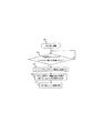
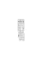
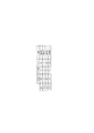
図5−1、図5−2は、それぞれOLTからONUへの光信号の信号構成図である。
10GPONの光信号の構成は現状未規定であるが、GPONと10GPONのどちらも可変長のデータを扱うものなので、現在勧告で規定されたGPONと同様な信号構成による時分割多重で各速度の信号を処理するのが現実(実用)的と考えられる。従って、以下の実施の形態では、GPONで規定された信号構成をベースにPONの動作説明を行う。もちろん、これらの信号構成やPONの動作は、一例であり、本実施の形態がこの構成や動作に限定されるものではない。また、図5−1と図5−2の構成の違いは、後述する下り信号130作製の過程で利用される下りBWマップの違いによる。
OLT200から各ONU300/310への信号は下り信号130と呼ばれ、図5−1(a)、図5−2(a)で示したように、例えば125μ秒のフレームに、オーバヘッドとペイロードとを含む。オーバヘッドは、各伝送速度について、各ONU300/310が信号の先頭を見つけるためのフレーム同期パタン5000/5001、各ONU300/310に対する監視・保守・制御に関する情報を送信するPLOAM領域5010/5011、各ONU300/310からOLT200への上り信号送信タイミングを指定するグラント指示領域5020/5021、該フレームの伝送速度毎のフレームペイロード5040/5041のタイミング情報及び各ONU300/310が次に受信する125μ秒のフレームにおける伝送速度毎のオーバヘッドのタイミング情報及び各ONU300/310が伝送速度の変更(光レベルの変動)に伴う受信信号レベルの変動への追随を可能にするために設けられたダミー信号5110/5111のタイミング情報を示した下りBWマップ5030/5031を含む。ペイロードは、各ONU300/310へのデータを時分割多重した1Gフレームペイロード5040、10Gフレームペイロード5041が格納されており、さらに、各伝送速度のオーバヘッドの間や各伝送速度のフレームペイロード間に前述したダミー信号5110/5111が挿入された構成となっている。この下り信号130は、各ONU300/310に同報される。各ONU300/310は、オーバヘッドの下りBWマップから得ている情報から、自ONUに対応する伝送速度の受信信号の到達するタイミングや、受信信号が自ONU宛の信号であるか否かを判定して、図15や図16に示すONUの構成例で説明する各種動作を行い、受信したデータを宛先端末400、410へ送信する。
(Signal configuration)
5A and 5B are signal configuration diagrams of optical signals from the OLT to the ONU, respectively.
10GPON optical signal configuration is currently unspecified, but since both GPON and 10GPON handle variable length data, each speed signal is time-division multiplexed with the same signal configuration as GPON specified in the current recommendation. Is considered realistic (practical). Therefore, in the following embodiment, the PON operation will be described based on the signal configuration defined by GPON. Of course, these signal configurations and PON operations are examples, and the present embodiment is not limited to these configurations and operations. Further, the difference in configuration between FIG. 5A and FIG. 5B is due to the difference in the downlink BW map used in the process of producing the
A signal from the
図5−1(b)、図5−2(b)は、各伝送速度のフレームペイロード5040/5041の詳細構成を示した構成図である。各ONU300/310宛のデータ(10Gペイロード5061や1Gペイロード5060)は、ONU毎のデータ識別子等各ONUでのデータ受信に用いられるGEMヘッダ(10G GEMヘッダ5051や1G GEMヘッダ5050)が付加された形でそれぞれのフレームペイロード5040/5041内部に時分割多重される。図5−1(c)、図5−2(c)はGEMヘッダ5050/5051の構成を示した構成図である。各バイトの詳細は勧告G.984に規定されたものであり、説明を省略する。
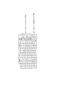
図6は、ONUからOLTへの光信号の構成例を示す信号構成図である。
各ONU300/310からOLT200への信号は上り信号150と呼ばれ、図6(a)で示したように、バーストデータ6120/6121と、バーストオーバヘッド6100/6101とを有する。バーストデータ6120/6121は、各ONU300/310の監視・保守・制御に関する情報を送信するPLOAM領域6020/6021、各ONU300/310が送信を待っているデータの量をOLT200に通知するキュー長領域6030/6031を含む制御信号6110/6111と、該ONUの端末400、410からのデータを入れた可変長のフレームペイロード6040/6041とを有する。バーストオーバヘッド6100/6101は、OLT200が各ONU300/310からのバーストデータ6120/6121を認識して処理するためのプリアンブル領域6000/6001と、デリミタ領域6010/6011とを有する。尚、プリアンブル領域6000/6001の前に示したガードタイム6200は、各ONUからの送信信号を分離するための無信号(光信号OFF状態)領域であり、勧告G.984では、このガードタイム6200とバーストオーバヘッド6100/6101の合計が最大12バイトと規定されている。図1で示したように、各ONU300/310からの上りは、光スプリッタ100を通った後に基幹光ファイバ110上で時分割多重され、多重光信号140となり、OLT200に伝送される。
FIGS. 5-1 (b) and 5-2 (b) are configuration diagrams showing the detailed configuration of the
FIG. 6 is a signal configuration diagram illustrating a configuration example of an optical signal from the ONU to the OLT.
A signal from each
図6(b)は、フレームペイロード6040/6041の詳細構成を示した構成図である。各ONU300/310からのデータ(1Gペイロード6311や5Gペイロード6310)は、下り信号130と同様にONU毎のデータ識別子等OLT200でのデータ受信に用いられるGEMヘッダ6300/6301が付加された形でフレームペイロード6040/6041内部に時分割多重される。同図(c)はGEMヘッダ6300/6301の構成を示した構成図である。各バイトの詳細は勧告G.984に規定されたものであり、説明を省略する。
尚、本実施の形態においては、各ONU300/310からの上り信号150の送信タイミングは、ITU−T勧告G.984で規定されたGPONと同様に決定されることができる。具体的には前述した、PONシステムの立上げ時にレンジングと称されるシステム運用に必要な制御パラメータを確定させ、OLT200や各ONU300/310に設定された後、OLT200が各ONU300/310から受信したキュー長レポートと契約に基づく許容トラヒックに基づき各ONUへ送信を許可するデータ量(帯域)を決定する。各ONU300/310へ該決定帯域に対応した送信許可タイミング(グラント指示)をグラント指示領域5020/5021で通知する。各ONU300/310は、該タイミングで上り信号150をOLT200に向け送信する。
FIG. 6B is a configuration diagram showing a detailed configuration of the frame payload 6040/6041. The data (
In this embodiment, the transmission timing of the
(OLT)
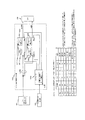
図7は、OLT200の構成例を示すブロック図である。
OLT200は、例えば、網IF7001と、パケットバッファ部7010と、GEMヘッダ生成部7180と、オーバヘッド生成部7170と、ダミー信号生成部7250と、下りPONフレーム組み立て部7020と、下り1G/10G信号切り替え部7030と、E/O7060と、WDMフィルタ7070と、O/E7080と、セレクタ7090と、1G ATC7100と、10G ATC7110と、上りPONフレーム分解部7120と、通信処理部7130と、パケットバッファ部7140と、網I/F7150と、レンジング信号終端部7210と、上り1G/10G切り替え制御部7205とを備える。また、下りBWマップ生成部7160は、後述するように、優先度別キュー情報監視部と、下りBWマップテーブル作製部と、ONU伝送速度情報記憶部又はONU伝送速度情報記憶・閾値決定部を有する。
(OLT)
FIG. 7 is a block diagram illustrating a configuration example of the
The
OLT200は、各ONU300/310へ送信する伝送速度10Gbit/秒のデータを上位網20から網IF7001で受信する。網IF7001は、上位網とのインタフェースである。受信データはパケットバッファ部7010に到達し、その中の優先度別キューバッファ(後述する図8−1、図8−2の7010−1〜7010−n)に一旦蓄積される。下りPONフレームの組み立ては、下りBWマップ生成部7160が生成する下りBWマップ(詳細は後述する)に基づき、優先度別キューバッファ(後述する図8−1、図8−2の7010−1〜7010−n)、GEMヘッダ生成部7180、オーバヘッド生成部7170、ダミー信号生成部7250、下りPONフレーム組み立て部7020が動作して行われる(詳細は後述する)。その後、下りBWマップに基づき作製された下りPONフレーム内の信号について、下り1G/10G信号切り替え部7030が必要な部分を1G信号へ変換させ、下り信号130を生成する。生成された下り信号130は電気信号を光信号に変換するE/O7060やWDMフィルタ7070を経由し、各ONU300/310へ送信される。
The
また、図1で示した上り信号140を受信する際は、まずWDMフィルタ7070、O/E7080、セレクタ7090を通過する。このとき、この上り信号140に対応したグラント指示(図10)を参照し、伝送速度に応じて1G ATC7100、10G ATC7110のいずれかを経由して上りPONフレーム分解部7120へ到達する。各ATCには、自系伝送速度のデータの到達時にリセット信号が挿入される。このリセット信号は、各ONU300/310からの上り信号(図1:150)が時分割多重されてOLT200で受信されるが、この光信号のレベルがばらつくため、各上り信号150のそれぞれを受信する毎に一旦OLT200の受信回路7100、7110で信号受信レベルをリセットして、高速かつ正確な上り信号受信を実施させる効果も持つ。その後、上りPONフレーム分解部7120が上りPONフレームを分解し、通信処理部7130へペイロード情報を転送する。通信処理部7130は、転送されたペイロード情報をイーサパケットへ処理し、パケットバッファ部7140へ転送し、網IF7150を通じて上位網へ通信させる。
また、キュー長レポートを得たOLT200は、新たなグラント指示を作製する。具体的には、上りPONフレーム分解部7120が上りPONフレームから分解したキュー長レポートをグラント指示生成部7190へ送る。キュー長レポートには、各ONU300/310からの次回送信時の送信希望の情報量などが掲載されている。この情報に基づき、グラント指示生成部7190は、グラント指示を生成する。具体的な生成法は、G.984に規定されているので説明を省略する。このとき、例えば下りBWマップ生成部7160のONU伝送速度情報記憶部又はONU伝送速度情報記憶・閾値決定部がグラント指示生成部7190へONU毎の伝送速度情報(図4(c))を通知している。本実施の形態で規定するグラント指示は、従来のグラント指示にこのONU毎の伝送速度情報を加えたものである(図10)。このグラント指示を受け取った上り1G/10G切り替え制御部7205が、受信するタイミングによって、O/E7080、セレクタ7090、1G ATC7100、10G ATC7110を切り替えることで、OLT200はエラーを起こすことなく、各ONU300/310からのデータを受信できる。
When the
The
(ONU)
図15は、10G用ONU300の構成例を示すブロック図である。図16は1G用ONU310の構成例を示すブロック図である。
1G用ONU310の各ブロックの機能は、10G用ONU300と伝送速度の違いに対応させれば、機能は同一のもとなるので、以下10G用ONU300について説明し、1G用ONU310の詳細な説明は省略する。
10G ONU300は、例えば、WDMフィルタ15000と、O/E15010と、10G AGC15020と、下りPONフレーム分離部15040と、下りBWマップ終端部15050と、1G/10G信号タイミング制御部15060と、フレーム振分部15080と、パケットバッファ部15090、15110と、ユーザI/F15100と、グラント終端部15070と、レンジングリクエスト終端部15180と、GEMヘッダ生成部15130と、オーバヘッド生成部15140と、キュー長監視部15150と、送信制御部15120と、上りPONフレーム生成部15160と、E/O15170を備える。オーバヘッド生成部15140は、レンジングレスポンス生成部15190を有する。パケットバッファ部15090、15110、ユーザIF15100は、適宜の数を有することができる。
(ONU)
FIG. 15 is a block diagram illustrating a configuration example of the
The function of each block of the
The
まず、下り信号の受信について説明する。支線光ファイバ120から受信した下り信号130は、WDMフィルタ15000を介して光信号を電気信号に変換するO/E15010で電気信号に変換される。O/E15010の後段には、受信信号を一定のレベルへ調整する機能を有するAGC(Automatic Gain Control)と呼ばれる自動利得調整回路が存在する(10G AGC15020)。本実施の形態では、下り信号130が1G信号と10G信号が混在されているので、本来ならばこのAGCが高機能なものでなければ1G信号と10G信号の受信信号レベルの切り替わりに即座に対応できず、一部読み取り不可の部分が発生する場合がある。しかし、本実施の形態では下り信号130へダミー信号5110/5111を挿入していることで、追随するまでの時間の間はダミー信号が流され、本来のデータの受信にはエラーが起こらない。10G AGC15020から転送された下りPONフレームは、下りPONフレーム分離部15040にて、下りPONフレームの分離が行われる。
下りPONフレーム分離部15040は、受信した下りPONフレームに多重化されたオーバヘッドやペイロードを分離するもので、詳細な動作は省略するが、フレーム同期パタン5001で下り信号130の先頭を見つけると、PLOAM領域5011に入っていたPON制御メッセージに基づき、ONUの動作に必要な設定を行ったり、自ONUの監視結果やOLT200に要求する制御内容等を含む制御メッセージを作製して上り信号150のPLOAM領域6020に入れてOLT200に送信する。尚、下りPONフレーム分離部15040にて分解されたオーバヘッド内の下りBWマップを下りBWマップ終端部15050が確認した後、下りBWマップ終端部15050はその情報を1G/10G信号タイミング制御部15060へ通知する。1G/10G信号タイミング制御部15060が次回到達時のフレームのオーバヘッドに対し、そのタイミング情報を下りPONフレーム分離部15040へ通知することで、下りPONフレーム分離部15040は1G信号と10G信号の判断を行いながら、10G信号のオーバヘッドを読み取り、処理できる。また、グラント終端部15070は、グラント指示領域5021に入っていたグラント指示から自ONU宛のグラント指示を抽出し、自ONUの上り信号の送信タイミングに応じて、パケットバッファ部15110の情報を抽出する。抽出された情報により上り信号150を生成し、OLT200に送信する。
First, reception of a downlink signal will be described. The
The downlink PON
更に、下りPONフレーム分離部15040は、10Gフレームペイロード5041に多重化された10G GEMヘッダ5051の内容を確認する。ここで、10G GEMヘッダ5051が自ONU宛のものであれば、該GEMヘッダに続く10Gペイロード5061のデータをフレーム振分部15080に送信し、他のGEMヘッダや ペイロードのデータは廃棄する。この際、先ほど取り込んだオーバヘッド内の下りBWマップには該下りPONフレームのフレームペイロード内の自身が対応可能な伝送速度の情報の状況や自ONU宛の信号の状況が含まれている。下りPONフレーム分離部15040は、1G/10G信号タイミング制御部15060からそのタイミング情報を取得することで、1G信号であるため無視して構わない領域(O/E15010や10G AGC15020や下りPONフレーム分離部15040は10G信号用なので、1G信号には正確に動作できず、本来ならば1G信号をエラー信号として扱ってしまう)や10G信号成分を判別できる。また、自ONU宛のGEMヘッダ5051や10Gペイロード5061を判別することができ、目的の自ONU宛のデータを取得することができる。
フレーム振分部15080は、受信したデータを宛先の端末400/410毎にパケットバッファ部15090に一旦蓄積後、端末とのインタフェースであるユーザIF15100を介して各端末400/410に送信する。
Further, the downstream PON
The
次に、上り信号の送信について説明する。以下、図15、図16の符号をあわせて示す。
各端末400/410が送信するデータは、ユーザIF15100/16100を介してパケットバッファ15110/16110に一旦蓄積される。グラント終端部15070/16070が受け取ったグラント指示領域5020/5021のタイミング情報に基づき、上りPONフレーム生成部15160/16160で以下のように上り信号150に組み立てられる。上り信号150は、E/O15170/16170で電気信号から光信号に変換された後、WDMフィルタ15000/16000を介して支線ファイバ120経由でOLT200に送信される。
Next, uplink signal transmission will be described. Hereinafter, the reference numerals in FIGS. 15 and 16 are also shown.
Data transmitted by each terminal 400/410 is temporarily stored in the packet buffer 15110/16110 via the user IF 15100/16100. Based on the timing information of the
(1)OLT200によりグラント指示で決定された帯域(送信を許可するデータ量)だけデータを各パケットバッファ部15110/16110から読み出して5Gペイロード(図6:6310)又は、1Gペイロード(図6:6311)を生成する。
(2)GEMヘッダ生成部15130/16130が生成したGEMヘッダ(図6:6300/6301)を5Gペイロード6310や1Gペイロード6311の前に付けてフレームペイロード(図6:6040/6041)を作製する。GEMヘッダ6300/6301は図6(c)に示した構成で、各バイトの詳細は勧告G.984に規定されたもので説明を省略する。
(3)送信制御部15120/16120は、自ONU300/310の監視結果やOLT200に要求する制御内容等を含む制御メッセージを上り信号150のPLOAM領域6020/6021に入れる。また、キュー長監視部15150/16150は、各パケットバッファ部15110/16110に蓄積されたOLT200への送信を待っているデータの量を監視し、このデータ量をキュー長レポートとしてPLOAM領域6020/6021とフレームペイロード6040/6041の間に規定されたキュー長領域6030/6031に入れる。
(4)PLOAM領域6020/6021とキュー長領域6030/6031を含む制御信号6110/6111がフレームペイロード6040/6041の前に付加されたバーストデータ6120/6121には、オーバヘッド生成部15140/16140が生成したプリアンブル領域6000/6001とデリミタ領域6010/6011を含むバーストオーバヘッド6100/6101が更に前に付加され、上り信号150が組み立てられる。この上り信号150は、OLT200から指定されたグラント指示に基づき、ガードタイム6200も付加して指定されたタイミングで送信される。
(1) Data is read from each packet buffer unit 15110/16110 by the bandwidth determined by the grant instruction by the OLT 200 (data amount permitted to be transmitted), and the 5G payload (FIG. 6: 6310) or 1G payload (FIG. 6: 6311). ) Is generated.
(2) The GEM header (FIG. 6: 6300/6301) generated by the GEM
(3) The
(4)
(立ち上がり時の動作)
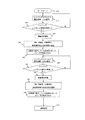
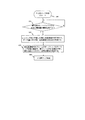
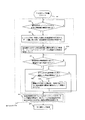
図2−1、図2−2は、立ち上がり時のOLTの動作を示したフロー図である。図3−1は、1G ONU310の立ち上がり時の動作を示すフロー図である。図3−2は、10G ONU300の立ち上がり時の動作を示すフロー図である。ただし、図2−1と図2−2のフローの違いは、後述する閾値決定に関するステップ(図2−2:2110)の有無が異なるものである。
OLT200とONU300/310は立ち上がり時に、レンジングと呼ばれる距離補正を行う。まずOLT200側では、レンジングリクエスト生成部7230がレンジングリクエスト信号を各ONU300/310に対し送信する。なお、1Gと10Gのレンジング処理のいずれを先にやってもよい。このとき、OLT200の配下には、伝送速度の異なるONU300/310が配置されているので、まずOLT200は伝送速度の遅い1G ONU310に対して、1G信号でレンジングリクエスト信号(図2−1、図2−2ともに2010)を送信する。10G ONU300は、1G信号でレンジングリクエスト信号を受け取った際、エラーとして認識するため、レンジングレスポンス信号を返さない。このとき、詳細は後述するが、OLT200内ではオーバヘッド生成部7170や下りPONフレーム組み立て部7020は10G信号で信号を組み立てているので、レンジングリクエスト生成部7230は1G信号のレンジングを行う間、下り1G/10G信号切り替え部7030に対して1G信号へ速度変換するように指示を出す。
(Operation at startup)
FIGS. 2-1 and 2-2 are flowcharts showing the operation of the OLT at the time of rising. FIG. 3A is a flowchart showing the operation of the
The
1G信号のレンジングリクエスト信号を受信した1G ONU310(図3−1:3020)では、レンジングリクエスト終端部16180がレンジングリクエスト信号を受け取り、レンジングレスポンス生成部16190がレンジングレスポンス信号を生成し、レンジングレスポンス信号を返す(図3−1:3030)。10G ONU300は、1G信号を受信した際エラー信号として認識するので、レンジングレスポンス信号を送信しない。OLT200は、レンジング信号終端部7210でレンジングレスポンス信号を受信し、受け取ったレンジングレスポンス信号を基にして距離測定の実施やONU IDの確定を行う。OLT200がレンジングレスポンス信号を受け取る際、受け取る伝送速度は1G信号なので、レンジングリクエスト生成部7230が上り1G/10G切り替え制御部7205に対して1G信号で受信するよう指令を出している。また、OLT200内のONU ID生成部7240がONU伝送速度情報記憶部8010もしくはONU伝送速度情報記憶・閾値決定部8030へ割り当てたONU IDを通知する。また、レンジングリクエスト生成部7230も、下りBWマップ生成部7160内のONU伝送速度情報記憶部8010もしくはONU伝送速度情報記憶・閾値決定部8030へ現在のレンジングリクエスト信号の伝送速度を通知している。ONU伝送速度情報記憶部8010もしくはONU伝送速度情報記憶・閾値決定部8030は前述の情報を基にして、図4(a)のようなONU IDと伝送速度を対応させて記憶する。その後、1G ONU310は距離測定結果やONU IDを受け取り、port IDの設定を行い通常運用へ移行する(図2−1、図2−2ともに2020〜2050。図3−1:3040、3050)。なお、距離測定の仕方やONU IDやport IDの割り当ての詳細内容は、G.984に記載されているので、説明を省略する。
In the 1G ONU 310 (FIG. 3-1: 3020) that has received the ranging request signal of the 1G signal, the ranging
次にOLT200は、10G信号のレンジングリクエスト信号を配下の各ONU300/310へ送信する(図2−1、図2−2ともに2060)。このとき、1G ONU310は10G信号のレンジングリクエスト信号を受け取った際、エラーとして認識するため、レンジングレスポンス信号を返さない。10G ONU300は、レンジングリクエスト信号を受信し、1G ONU310と同様に、OLT200へレンジングレスポンス信号を送信し、OLT200との間で距離測定の実施、ONU IDやport IDの設定を行いながら通常運用へ移行する(この流れが図2−1、図2−2ともに2070〜2100。図3−2:3070〜3100)。このときOLT200は10G信号で送受信を行っているので、レンジングリクエスト生成部7230が10G信号でレンジングを行う間は、下り1G/10G信号切り替え部7030や上り1G/10G切り替え制御部7205に対して10Gで動作させるように指示を出している。また、OLT200は1G ONU310の時と同様に10G ONU300に対し、距離測定の実施、ONU IDやport IDの設定などを行いつつ、ONU伝送速度情報記憶部8010もしくはONU伝送速度情報記憶・閾値決定部8030が図4(b)のようなONU IDと伝送速度を対応して記憶する。その後、先に記憶した図4(a)との情報を組み合わせ、最終的にONU伝送速度情報記憶部8010もしくはONU伝送速度情報記憶・閾値決定部8030が図4(c)のように、配下全てのONU IDと伝送速度の対応表を完成させる。OLT200は配下全てのONU300/310に対し、距離測定の実施、ONU IDやport IDの設定や全ONU300/310の伝送速度の状態を把握しながら立ち上がり処理を行い、通常運用へ移行する(図2−1、図2−2ともに2120)。このとき、ONU伝送速度情報記憶部8010またはONU伝送速度情報記憶・閾値決定部8030は図4(c)のONU IDと伝送速度との対応表を下りBWマップテーブル作製部(図8−1の8020−1、図8−2の8020−2)へ通知する。通知されたONU IDと伝送速度との対応表は、通常運用時に図8、図9、図11などで後述する下りBWマップ生成に利用される。
Next, the
また、図4(c)のONU IDと伝送速度との対応表は、ダミー信号を極力減らした下り信号130の構成を作製する場合、伝送速度毎の閾値決定のために利用されることもある。具体的には、図4(c)の対応表が完成すると、OLT200内のONU伝送速度情報記憶・閾値決定部8030は、下り信号130作製時におけるフレームペイロードの伝送速度毎に、確保する帯域(又は送信タイミングの長さ)の閾値・割合を決定する(図2−2:2110)。図4(c)を例とすると、1G ONU310は配下に16台、10G ONU300は48台存在する。このとき、例では10G ONU300の方が配下に多く収容されているとわかるので、通常運用時の下り信号130作製時には配下のONUの比率通りに、フレームペイロード全体の75%を10G信号、残りの25%を1G信号の割り当ての閾値と決定することができる。尚、フレームペイロード全体の75%や25%に相当する帯域の値、送信タイミングの長さ等の閾値を求めてもよい。前述の割り当ては一例であり、本実施の形態がこの割り当て方に固執するものではなく、適宜割当てることができる。また、10G信号と1G信号を割り当てる閾値を決定する場合は、優先すべき伝送速度のフレームや顧客との契約などで割り当ての閾値を変更させてもよい。ONU伝送速度情報記憶・閾値決定部8030は前述の10G信号と1G信号を割り当てる閾値を決定すると、その閾値を下りBWマップテーブル作製部(図8−2:8020−2)へ通知する。通知された情報は、通常運用時に図8−2、図9−2、図11などで後述する下りBWマップ生成に利用される。なお、ステップ2110は省略してもよい。
In addition, the correspondence table between ONU IDs and transmission rates in FIG. 4C may be used to determine a threshold value for each transmission rate when a configuration of the
(下りBWマップの生成法1)
図8−1は、OLT200に備えられた下りBWマップ生成部7160の構成例を示すブロック図(1)である。また、図9−1に下りBWマップ生成のフロー図(1)を示す。
まず、図8−1に示す下りBWマップ生成部7160(ここでは7160−1とする)の構成及び図9−1に示した下りBWマップ生成のフローに従うことによって作製される下りBWマップ生成の過程を示す。ここで生成される下りBWマップに基づいて、図5−1に示した下り信号130が作製される。図8−1の下りBWマップ生成部7160−1はパケットバッファ部7010の各優先度別キューバッファ7010−1〜7010−nから優先度別キュー情報を得る優先度別キュー情報監視部8000と、レンジング時の結果からONU毎の伝送速度情報を記憶しているONU伝送速度情報記憶部8010と、図9−1のフローに従って下りBWマップを作製する下りBWマップテーブル作製部8020−1とを有する。
優先度別キュー情報監視部8000が各優先度別キューバッファ7010−1〜7010−nからキュー情報を取り込む。このキュー情報の中には、下り信号130で送信される各ONU宛の宛先や送信量などの情報が含まれている。ONU伝送速度情報記憶部8010は、下りBWマップテーブル作製部8020−1へ事前に各ONUの適用伝送速度(図4(c))を通知している。各ONUの適用伝送速度を得ている下りBWマップテーブル作製部8020−1は各情報のデータ量や優先度や宛先を照らし合わせ、下りBWマップを生成する。
例を挙げると、優先度別キューバッファには優先度が優先度1から優先度4まで設定されており、優先度1にはONU番号33、優先度2にはONU番号1、優先度3にはONU番号34、優先度4にはONU番号35の情報が、それぞれ格納されているとする。優先度別キュー情報監視部8000は、この格納された各宛先と情報量を取り込み、下りBWマップテーブル作製部8020−1へ通知する(図9−1:9010)。下りBWマップテーブル作製部8020−1は、事前にONU伝送速度情報記憶部8010が作製した各ONUの伝送速度情報(図4(c))を参照し、送信する情報の優先度と、宛先のONU番号(又はID)と各宛先に対する伝送速度(図中Signal)と確保する帯域(データ量)の対応表を作製する(図9−1:9020、図11−1)。下りBWマップテーブル作製部8020−1は図11−1の対応表を作製した後、信号の伝送速度が変わる箇所(例えば、10G信号から1G信号へ変わる箇所や、1G信号から10G信号へ変わる箇所)へ挿入するダミー信号5110/5111の情報や、今回作製しているフレームの次に送信するフレームのオーバヘッド部のタイミング情報を追加する(図9−1:9070、図11−2)。また、帯域に応じて送信タイミング情報(Start、End)を割当てる。この図11−2の一覧が下りBWマップとなる。図11−2の例では、例えば、優先度順にペイロードを並べている。
(Downlink BW map generation method 1)
FIG. 8A is a block diagram (1) illustrating a configuration example of the downlink BW
First, the downstream BW map generation unit 7160 (herein referred to as 7160-1) shown in FIG. 8A and the downstream BW map generation created by following the downstream BW map generation flow shown in FIG. Show the process. Based on the downlink BW map generated here, the
The priority-specific queue
For example, the priority queue buffers are set with priority levels from
ダミー信号5110/5111は、下り信号130の内部が1G信号から10G信号へ切り替わる場合は、各ONU300/310は10G信号に対して追随をしなければならないので、10G信号のダミー信号5110を用いる。また、下り信号130の内部が10G信号から1G信号へ切り替わる場合は、各ONU300/310は1G信号に対して追随をしなければならないので、1G信号のダミー信号5111を用いる。このダミー信号5110/5111の効果で、各ONU300/310は、フレーム全体の中で伝送速度の変更(光レベルの変動)に伴う受信信号レベルの変動が生じた時に、その変動に追随する時間を得ることが可能である。つまり、ダミー信号を受信している間は各ONU300/310は受信エラーを起こすことがあるが、その間は本来のデータとは関係無いデータを受信しているので、エラーを起こしていても問題無い。ONU300/310は、ダミー信号を受信し終わる時には受信信号レベルの追随を完了しているので、ONU300/310は本来のデータを受信信号レベルの追随が完了した後に受信すればよい。なお、ダミー信号の長さは、例えば、各ONUの性能によって予め決めるなど、適宜定めることができる。また、各ONU300/310は受信する下り信号130内に格納されている下りBWマップを参照することによって、該フレームのフレームペイロード内の自身が対応可能な伝送速度の信号や自宛のフレームペイロードを判別し、自伝送速度の信号を、エラー無く受信することが可能になる。その他にも各ONU300/310は該フレームの次に到達するフレームのオーバヘッド部のタイミング情報を得ることによって、次フレーム受信時にオーバヘッド部の受信が可能となり、そのオーバヘッド部に格納されている下りBWマップを参照することによって、そのフレームのフレームペイロードの状況を把握し、そのフレーム全体をエラー無く受信することができる。
The
(下りBWマップの生成法2)
図8−2は、OLT200に備えられた下りBWマップ生成部7160の構成例を示すブロック図(2)である。また、図9−2に下りBWマップ生成のフロー図(2)を示す。下りBWマップ生成部7160を図8−2に示す構成を用い、図9−2の下りBWマップ生成のフローを適用すると、図5−2に示した下り信号130が生成される基となる下りBWマップが生成される。下りBWマップ生成部7160(ここでは7160−2とする)の構成は図8−1の場合と比べると、ONU伝送速度情報記憶部8010の代わりにONU伝送速度情報記憶・閾値決定部8030が搭載されている。また、下りBWマップテーブル作製部8020−2は図9−2の下りBWマップ生成のフローに従って下りBWマップを生成する。図9−2の下りBWマップ生成のフローは、図9−1の下りBWマップ生成のフローに比べ、OLT200が決定した閾値に基づいてフレームペイロードの割り当てを行うフローを追加したものとなっている。
ここでは、同じ伝送速度のペイロードをまとめて、挿入されるダミー信号の数を抑え、ダミー信号によるリソース消費を抑える。
優先度別キュー情報監視部8000は図8−1の説明の時と同様に、各優先度別キューバッファ7010−1〜7010−nからキュー情報を取り込む。このキュー情報の中には、下り信号130で送信される各ONU宛の宛先や送信量などの情報が含まれている。ONU伝送速度情報記憶・閾値決定部8030は、下りBWマップテーブル作製部8020−2へ事前に各ONUの適用伝送速度(図4(c))と伝送速度毎のフレーム生成時の閾値を通知している。各ONU300/310の適用伝送速度を得ている下りBWマップテーブル作製部8020−2は各情報のデータ量や優先度や宛先の他に通常運用前に決定した伝送速度毎の情報量の閾値を照らし合わせ、下りBWマップを生成する。
(Downlink BW map generation method 2)
FIG. 8-2 is a block diagram (2) illustrating a configuration example of the downlink BW
Here, the payloads having the same transmission rate are collected, the number of inserted dummy signals is reduced, and resource consumption by the dummy signals is reduced.
The priority-specific queue
例を挙げると、優先度別キューバッファには優先度が優先度1から優先度4まで設定されており、優先度1にはONU番号33、優先度2にはONU番号1、優先度3にはONU番号34、優先度4にはONU番号35の情報が、それぞれ格納されているとする。優先度別キュー情報監視部8000は、この格納された各宛先と情報量を取り込み、下りBWマップテーブル作製部8020−2へ通知する(図9−2:9010)。下りBWマップテーブル作製部8020−2は、事前にONU伝送速度情報記憶・閾値決定部8030が作製した各ONUの伝送速度(図4(c))を参照し、送信する情報の優先度と宛先と各宛先に対する伝送速度と確保する帯域(データ量)の対応表を作製する(図9−2:9020、図11−1)。その後、伝送速度毎の情報量の閾値(例えば、10G信号ならばペイロードに使用可能な帯域の75%、1G信号ならばペイロードに使用可能な帯域の25%)を参照し、フレームペイロードの領域を確保していく。具体的には、10G信号のフレームペイロードを構成する場合、優先度1、優先度3、優先度4のフレーム情報を取り出して帯域の確保をするが、合計した帯域の合計が前述したように閾値として決定しているフレームペイロード全体の75%を超えていない場合は、そのまま10G信号のフレームペイロードとして確保していき、全体の75%の閾値を超えている場合は、優先度の最も低い優先度4のフレームから順次除いていき、閾値を超えない程度になった時に、その確保したフレームの領域を10G信号のフレームペイロードとして設定する。1G信号についても同様の操作を行う。ここで、片方の伝送速度のフレームペイロードが閾値を超え、もう片方の伝送速度のフレームペイロードが閾値以下で確保された場合は、閾値を越えた伝送速度のフレームペイロードの閾値を増やし、増えた帯域へ搭載できなかったフレームを搭載して、効率の良いフレームペイロード構成を作り出す(この流れが、図9−2:9030〜9060)。このように伝送速度毎にフレームペイロードを集中して構成するようにすることで、下り信号130には本来関係の無いダミー信号の数を最低限に抑えることができる。
For example, the priority queue buffers are set with priority levels from
こうしてフレームペイロードの構成を決定した下りBWマップテーブル作製部8020−2は、図8−1、図9−1の説明の時と同様に、各伝送速度が切り替わる箇所に設けるダミー信号5110/5111の情報や次フレーム送信時のフレームに搭載されるオーバヘッド部のタイミング情報を加え、下りBWマップを図11−3のように生成する(図9−2:9070、9080)。ダミー信号を加える効果や次回送信するフレームのオーバヘッド部のタイミング情報を追加する効果は前述した通りなので、ここでの説明は省略する。
尚、これらの図中に示した割り当て帯域は一例であり、本実施の形態がこの帯域に縛られるものではない。
下りBWマップテーブル作製部8020は生成した下りBWマップを、下りPONフレームのオーバヘッド部に搭載させるだけでなく、下り1G/10G信号切り替え部7030へも通知する。通知を受けた下り1G/10G信号切り替え部7030は、その下りBWマップを基にして、下りPONフレーム組み立て部7020から送られる下りPONフレームを10G/1Gへ振り分ける。
尚、先の例では、上位網20からのデータ振り分けを優先度別に優先度1〜優先度4と、4段階に分割しているが、これは振り分け例として挙げており、必ずしもこの分割数を規定しているわけではなく、適宜の分割数でよい。また、グラント指示や下りBWマップを除くオーバヘッド部やGEMヘッダの生成は、勧告G.984で定められているので、ここでは省略する。
The downlink BW map table creation unit 8020-2 that has determined the frame payload configuration in this way, as in the description of FIGS. 8A and 8A, the
Note that the allocated bandwidth shown in these drawings is an example, and the present embodiment is not limited to this bandwidth.
The downlink BW map table creation unit 8020 not only mounts the generated downlink BW map on the overhead part of the downlink PON frame but also notifies the
In the previous example, the data distribution from the higher-level network 20 is divided into four levels of
(下り信号の生成)
OLT200の下りPONフレーム組み立て部7020は、下りBWマップ生成部7160が生成する下りBWマップに基づいて動作するパケットバッファ部7010、GEMヘッダ生成部7180、オーバヘッド生成部7170、ダミー信号生成部7250を用いて以下のように下り信号130を組み立てる。
(1)オーバヘッド生成部7170からの信号を受けフレーム同期パタン5000/5001、PLOAM領域5010/5011、グラント指示領域5020/5021、下りBWマップ5030/5031を含むオーバヘッド部を組み立てる。尚、オーバヘッド部を構成している、フレーム同期パタン、PLOAM領域、グラント指示領域、下りBWマップは伝送する伝送速度分用意する。また伝送速度が変更される箇所には、ダミー信号生成部7250がダミー信号5110/5111を設置する。ダミー信号5110/5111は、伝送速度が1G信号から10G信号へ切り替わる場合は10Gダミー信号5110を設置し、伝送速度が10G信号から1G信号へ切り替わる場合は1Gダミー信号5111を設置する。これは、各ONU300/310が伝送速度の変更(光レベルの変動)に伴う受信信号レベル変動への追随を可能にするため、ダミー信号5110/5111は切り替わる後の伝送速度のものが必要なためである。
(2)オーバヘッド部の後のフレームペイロードに各ONU300/310宛のデータを、該フレーム用に生成された下りBWマップの決定順に各ONU300/310宛のGEMヘッダ5050/5051をGEMヘッダ生成部7180から受け、データを入れる。
(3)フレーム長が125μ秒になるようフレームペイロード5040/5041内に時分割多重する各ONU300/310宛のデータの長さと順序を下りBWマップが定めているので、この決定に従い(2)を繰り返す。また(1)と同様に、ダミー信号生成部7250がフレームペイロード5040/5041間の各伝送速度の切り替え時に下りBWマップに従い、ダミー信号5110/5111を設置する。
下りPONフレーム組み立て部7020で組み立てられた下りPONフレームは、生成された下りBWマップの該フレームのタイミング情報に基づき、下り1G/10G信号切り替え部7030にて1G信号と10G信号へと振り分けられる。このとき、オーバヘッド部は、複数分(本実施の形態では1G信号用と10G信号用の2個分)作製されているので、複数のオーバヘッド部のタイミングに合わせて、下り1G/10G信号切り替え部7030が働くことで、オーバヘッド部分も1G信号の構成が生成される。こうして下り信号130が構成され、光変調部(E/O:7060)で電気信号から光信号に変換され、WDMフィルタ7070を介して基幹光ファイバ110や光スプリッタ100や支線光ファイバ120を経由し、各ONU300/310に同報される。なお、伝送速度に応じて出力する光信号のレベルを変えてもよい。
(Downlink generation)
The downlink PON
(1) The overhead unit including the
(2) The data addressed to each
(3) The downstream BW map defines the length and order of data addressed to each
The downlink PON frame assembled by the downlink PON
(各ブロックの具体的構成例)
図12は、OLTに備えた下り1G/10G信号切り替え部7030の構成例を示したブロック図である。
下り1G/10G信号切り替え部7030は10G書込みCLK(クロック)12020−1、10G読出しCLK12030を内蔵したメモリ部A12010と10G書込みCLK12020−2、1G読出しCLK12050を内蔵したメモリ部B12040、書込み・読出し制御部12005を内蔵したスケジューラ12000を有する。下りPONフレーム組み立て部7020で作製された下りPONフレームは下り1G/10G信号切り替え部7030内のメモリ部A12010、メモリ部B12040へ転送される。このとき、OLT200はフレーム内の1G信号へ変換すべき箇所を下りBWマップを生成することで把握している。下りBWマップ生成部7160は下りBWマップの情報をスケジューラ12000へ転送している。スケジューラ12000は下りBWマップ生成部7160から該フレームのタイミング情報を受け取り、書込み・読出し制御部12005がメモリ部A12010、メモリ部B12040へ対し、到達するフレームの書込みを指示する。このとき、フレームペイロードのタイミング情報は、この下りPONフレームを作製する時に利用した下りBWマップを参照すればよいが、オーバヘッド部のタイミング情報は、この下りPONフレームの前に送信した下りPONフレームを作製する時に利用した下りBWマップを参照する。具体的には、スケジューラ12000内の書込み・読出し制御部12005は下りBWマップから10G信号部分についてはメモリ部A12010へ書込み指示を与え、1G信号へ変換する部分についてはメモリ部B12040へ書込みを指示する。両者のメモリには10Gの速度で書込みを行うための10G書込みCLK12020が搭載されているので、問題無く書込みが行われる。その後スケジューラ12000内の書込み・読出し制御部12005は下りBWマップに従って、各メモリ部へ読出し指令を出す。このとき、メモリ部A12010は10Gの速度で読出しを行うための10G読出しCLK12030で読出しを行い10G信号がそのまま転送され、メモリ部B12040は1Gの速度で読出しを行うための1G読出しCLK12050で読出しを行い1G信号へ変換して転送する。読み出された10G信号、1G信号はE/O7060へ転送される。尚、通常運用前のレンジング時において、1G信号でレンジングを行う時はレンジングリクエスト生成部7230がスケジューラ12000に対し、転送されてくるフレームを常に1G信号でE/O7060へ転送するよう指令を出し、10G信号でレンジングを行う時はレンジングリクエスト生成部7230がスケジューラ12000に対し、転送されてくるフレームを常に10G信号でE/O7060へ転送するよう指令を出している。本実施の形態で述べた構成において、上位網20から転送される信号が10G信号で構成されているのは一例であり、本実施の形態がこの数値に限定されるものではない。上位網20から転送される伝送速度が異なる場合、適宜下り1G/10G信号切り替え部7030内の書込み用のCLKを変更するなどの対応をとればよい。
(Specific configuration example of each block)
FIG. 12 is a block diagram illustrating a configuration example of the
図13はE/O7060の構成例を示したブロック図である。
LD(レーザダイオード)ドライバ13000内には伝送速度毎のラインに差動動作のトランジスタ13030/13040が内蔵されている。このとき、電流源の容量を変更することで、伝送速度に対応した送信パワーを持った発光をLD13050が行うことができる。10G信号の送信パワーについてはまだ規定されていないが、現在のGPONと異なる場合は、こうした構成で伝送速度毎の送信パワーを実現すればよい。具体的には、差動動作のトランジスタ13030/13040に各伝送速度の信号が入力されると、接続されている電流源13010/13020の容量に対応した電流がLD13050に流れ、LD13050は特定の送信パワーを持った発光を行う。こうして、伝送速度毎の電気信号が光信号に変換され、各ONU300/310へ送信される。
図14は、O/E7080、セレクタ7090、1G ATC7100、10G ATC7110の構成例を示したブロック図である。
FIG. 13 is a block diagram showing a configuration example of E /
In an LD (laser diode)
FIG. 14 is a block diagram illustrating a configuration example of the O /
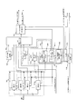
高電圧バイアス源14000に接続されたAPD(アバランシェフォトダイオード)14010が高電圧で逆バイアスされて受信した光信号をアバランシェ効果により増幅して電流に変換している。この増幅作用により、信号が微弱な光信号として入力される場合でも正しくデータを識別することが可能となる。変換された電流は抵抗と増幅器から構成されるTIA(トランスインピーダンスアンプ)14020で電圧に変換され、セレクタ7090へ転送される。このとき10G信号については、まだ明確に規定されていないが、1G信号と光レベルが異なる可能性がある。そうした場合、OLT200は自らが作製したグラント指示のタイミングに従い、伝送速度毎にTIA14020内の抵抗値を切り替えることで対応できる。具体的にはグラント指示に従い、OLT200内の上り1G/10G切り替え制御部7205がTIA14020内の抵抗を切り替える役割を持つMOSFET14030/14050へ切り替え信号を送ることで、TIA14020内の抵抗値を変更することができる。例えば1G信号用の抵抗14060を1kΩとしている場合、10G信号用の抵抗14040では、100Ωなどの抵抗値に設定すればよい。次にセレクタ7090ではTIA14020同様、方路を切り替えるためのMOSFET14080/14090が搭載されている。MOSFET14080/14090は上り1G/10G切り替え制御部7205からの指令によってO/E7080から転送されてくる受信信号を適切な方路へ切り替えて、後段の1G ATC7100、10G ATC7110へ転送している。このときATC(Auto Threshold Control)と呼ばれる自動閾値調整回路では振幅の1/2に閾値14120/14170が設定されて、0値または1値に識別された信号が出力される。増幅器14100/14150の出力はトランジスタ14110/14160のベースからエミッタへのダイオード機能を用いてピーク値検出が行われてコンデンサ14130/14180に保持されて、増幅器14100/14150の閾値14120/14170として与えられる。各ONU300/310からの信号受信直前にリセット信号がトランジスタ14140/14190に与えられ、コンデンサ14130/14180に保持された閾値14120/14170が放電されて0レベルまでリセットされる。閾値14120/14170はコンデンサ14130/14180の値に依存するが、10G信号にはまだ明確な規定が無いため、1G信号と10G信号を扱う場合閾値が異なることを考慮して、1G ATC7100のコンデンサ14180の容量を100pFとした場合、10G ATC7110のコンデンサ14130の容量は10pFとするように、2種類のコンデンサを搭載している。
An APD (avalanche photodiode) 14010 connected to a high
本実施の形態で述べた抵抗14040/14060の抵抗値やコンデンサ14130/14180の値は一例であり、本実施の形態がこの数値に限定されるものではない。
上述したOLT200の構成と動作によれば、1Gbit/秒で動作するGPONに新たな10Gbit/秒のような高速データの伝送が要求されるようになっても、これら伝送速度の異なる信号を混在収容して運用できる構成のOLTとONUを備えたPON、および、その通信方法が容易に提供出来るようになる。
以上で説明したように、本実施の形態のPON、OLT、ONUの構成と動作により、既存のPONの設備を収容しつつ新しいPONへと移行できるような、PONを混在させて運用出来るような構成のPONとその通信方法が容易に提供出来るようになる。また、複数の仕様(規格)の異なるPONを混在させて運用出来るような構成のPONとその通信方法を容易に提供出来るようになる。尚、複数のPONを混在させても、各PONの内容が誤って解釈されることはなく警報や誤動作が発生することがない。また、OLTから複数のONUへの通信信号は時分割多重されて伝送されるPONにおいて、伝送速度の異なる複数のONUを混在収容することを可能とし、通信サービス容量の拡大に要求が発生しても対応するOLTおよびONUのみ交換することで、通信装置の交換費用を抑制することが可能となる。
The resistance values of the resistors 14040/14060 and the values of the
According to the configuration and operation of the
As explained above, the configuration and operation of the PON, OLT, and ONU according to the present embodiment allows the operation of a mixture of PONs that can migrate to a new PON while accommodating existing PON equipment. A PON having a configuration and a communication method thereof can be easily provided. In addition, it is possible to easily provide a PON having a configuration in which a plurality of PONs having different specifications (standards) can be mixed and operated, and a communication method thereof. Even if a plurality of PONs are mixed, the contents of each PON are not misinterpreted and no alarm or malfunction occurs. In addition, a communication signal from an OLT to a plurality of ONUs can be mixedly accommodated with a plurality of ONUs having different transmission speeds in a PON that is time-division multiplexed and transmitted, and there is a demand for expansion of communication service capacity. Also, by exchanging only the corresponding OLT and ONU, it is possible to reduce the replacement cost of the communication device.
10 PON
100 スプリッタ
110、120 光ファイバ
130 下り信号
140、150 上り信号
200 OLT
300、310 ONU
400、410 端末
5110、5111 ダミー信号
5050、5051、6300、6301 GEMヘッダ
5060、5061 下り信号ペイロード
6310、6311 上り信号ペイロード
7010 パケットバッファ、キュー
7020 下りPONフレーム組み立て部
7230 レンジングリクエスト生成部
7250 ダミー信号生成部
8000 優先度別キュー情報監視部
8010 ONU伝送速度情報記憶部
8020 下りBWマップテーブル作製部
8030 ONU伝送速度情報記憶・閾値決定部
15020、16020 AGC
10 PON
100
300, 310 ONU
400, 410
Claims (14)
第1の伝送速度で前記親局と通信する第1の子局と、第2の伝送速度で前記親局と通信する第2の子局とを含む複数の子局と、
前記親局からの信号がスプリッタを介して各子局に送信されるための光ファイバ網と
を備え、
前記複数の子局は、
多重された信号の伝送速度の変化による受信信号のレベルの変化に追随して、受信信号を所定レベルに調整する自動利得調整回路
を有し、
前記親局は、
第1の伝送速度のペイロード及び/又はオーバヘッド情報と、第2の伝送速度のペイロード及び/又はオーバヘッド情報と、伝送速度が変化する箇所に挿入されるダミー信号とを時分割多重して前記子局に送信する受動光網システム。 A master station that performs time-division multiplexing and communication of signals of the first transmission rate and the second transmission rate;
A plurality of slave stations including a first slave station that communicates with the master station at a first transmission rate and a second slave station that communicates with the master station at a second transmission rate;
An optical fiber network for transmitting a signal from the master station to each slave station via a splitter;
The plurality of slave stations are
An automatic gain adjustment circuit that adjusts the received signal to a predetermined level following a change in the level of the received signal due to a change in the transmission speed of the multiplexed signal,
The master station is
The slave station performs time division multiplexing of the payload and / or overhead information of the first transmission rate, the payload and / or overhead information of the second transmission rate, and a dummy signal inserted at a location where the transmission rate changes. Passive optical network system to send to.
多重された信号が第1の伝送速度から第2の伝送速度へ変化する箇所には、第2の伝送速度のダミー信号を用い、
多重された信号が第2の伝送速度から第1の伝送速度へ変化する箇所には、第1の伝送速度のダミー信号を用いる請求項1に記載の受動光網システム。 The master station is
At the place where the multiplexed signal changes from the first transmission rate to the second transmission rate, a dummy signal of the second transmission rate is used,
2. The passive optical network system according to claim 1, wherein a dummy signal having the first transmission rate is used at a location where the multiplexed signal changes from the second transmission rate to the first transmission rate.
子局識別情報と該子局が通信する伝送速度情報とが対応して予め記憶された伝送速度情報記憶部と、
前記子局へ送信する信号の送信タイミングを決定し、前記伝送速度情報記憶部を参照して、各送信タイミングで送信される各子局への信号の伝送速度情報に基づき伝送速度が変化する箇所を判断し、該箇所にダミー信号を挿入するための送信タイミングを追加する帯域情報作製部と
を有する請求項1に記載の受動光網システム。 The master station is
A transmission rate information storage unit in which slave station identification information and transmission rate information with which the slave station communicates are stored in advance;
A location where the transmission rate changes based on the transmission rate information of the signal to each slave station transmitted at each transmission timing by determining the transmission timing of the signal to be transmitted to the slave station and referring to the transmission rate information storage unit The passive optical network system according to claim 1, further comprising: a band information generation unit that determines transmission timing and adds a transmission timing for inserting a dummy signal at the location.
第1の伝送速度の第1信号を前記光ファイバ網を介して前記複数の子局に送信し、及び、第2の伝送速度の第2信号を前記光ファイバ網を介して前記複数の子局に送信する信号送信部
を有し、
第1信号を受信した前記第1の子局から送信される第1応答信号を受信すると、該第1の子局識別情報に対応して、第1の伝送速度を示す伝送速度情報を前記伝送速度情報記憶部に記憶し、
第2信号を受信した前記第2の子局から送信される第2応答信号を受信すると、該第2の子局識別情報に対応して、第2の伝送速度を示す伝送速度情報を前記伝送速度情報記憶部に記憶する請求項4に記載の受動光網システム。 The master station is
A first signal having a first transmission rate is transmitted to the plurality of slave stations via the optical fiber network, and a second signal having a second transmission rate is transmitted to the plurality of slave stations via the optical fiber network. A signal transmission unit for transmitting to
When the first response signal transmitted from the first slave station that has received the first signal is received, transmission rate information indicating a first transmission rate is transmitted in correspondence with the first slave station identification information. Store in the speed information storage unit,
When a second response signal transmitted from the second slave station that has received the second signal is received, transmission rate information indicating a second transmission rate is transmitted in correspondence with the second slave station identification information. The passive optical network system according to claim 4, wherein the passive optical network system is stored in a speed information storage unit.
前記第1及び第2応答信号は、該レンジング処理におけるレンジングレスポンス信号である請求項5に記載の受動光網システム。 The first and second signals are ranging request signals in a ranging process for adjusting a difference in signal delay due to a difference in transmission distance from the master station to each slave station,
The passive optical network system according to claim 5, wherein the first and second response signals are ranging response signals in the ranging process.
前記子局へ送信するデータを格納するキューと、
前記キューに格納されているデータの宛先を示す前記子局識別情報を取得するキュー情報監視部と、
ダミー信号を生成するダミー信号生成部と、
前記帯域情報作製部での送信タイミングに従い、前記キューに記憶された各子局へのデータと、前記ダミー信号生成部からのダミー信号とを時分割多重したフレームを組み立てて出力するフレーム組み立て部と
をさらに有する請求項4に記載の受動光網システム。 The master station is
A queue for storing data to be transmitted to the slave station;
A queue information monitoring unit for acquiring the slave station identification information indicating a destination of data stored in the queue;
A dummy signal generator for generating a dummy signal;
A frame assembly unit that assembles and outputs a frame obtained by time-division multiplexing the data to each slave station stored in the queue and the dummy signal from the dummy signal generation unit according to the transmission timing in the band information generation unit; The passive optical network system according to claim 4, further comprising:
第1の伝送速度の信号が連続して送信されるように送信タイミングを決定し、第2の伝送速度の信号が連続して送信されるように送信タイミングを決定し、該第1の伝送速度の信号と第2の伝送速度の信号の間にダミー信号を挿入する請求項4に記載の受動光網システム。 The band information production unit
The transmission timing is determined so that the signal of the first transmission rate is continuously transmitted, the transmission timing is determined so that the signal of the second transmission rate is continuously transmitted, and the first transmission rate is determined. 5. The passive optical network system according to claim 4, wherein a dummy signal is inserted between the first signal and the second transmission rate signal.
第1の伝送速度のペイロードに割り当てる送信タイミングの長さと第2の伝送速度のペーロードに割り当てる送信タイミングの長さとの割合が予め設定され、第1の伝送速度のデータを該割合に応じた範囲で連続させて送信タイミングを決定し、第2の伝送速度のデータを該割合に応じた範囲で連続させて送信タイミングを決定する請求項8に記載の受動光網システム。 The band information production unit
A ratio between the length of the transmission timing assigned to the payload of the first transmission rate and the length of the transmission timing assigned to the payload of the second transmission rate is preset, and the data of the first transmission rate is within a range corresponding to the proportion. The passive optical network system according to claim 8, wherein the transmission timing is determined continuously and the transmission timing is determined by continuing data of the second transmission rate within a range corresponding to the ratio.
前記伝送速度情報記憶部を参照し、第1の伝送速度の子局の数と、第2の伝送速度の子局の数に従い、前記割合を決定する請求項9に記載の受動光網システム。 The band information production unit
The passive optical network system according to claim 9, wherein the ratio is determined according to the number of slave stations having a first transmission rate and the number of slave stations having a second transmission rate with reference to the transmission rate information storage unit.
前記割合に応じた範囲で第1及び第2の伝送速度のデータの送信タイミングを決定した後、いずれかの帯域が余っている場合には、該帯域を用いて第1又は第2の伝送速度のデータを送信する送信タイミングを決定する請求項9に記載の受動光網システム。 The band information production unit
After the transmission timing of the data of the first and second transmission rates is determined within the range according to the ratio, if any band is left, the first or second transmission rate is used using the band. The passive optical network system according to claim 9, wherein transmission timing for transmitting the data is determined.
前記子局は、該送信タイミングと伝送速度情報に従い、前記光ファイバ網から入力され、前記自動利得調整回路でレベルが調整された受信信号から、自子局の第1又は第2の伝送速度に対応するタイミングのデータを取り込む請求項4に記載の受動光網システム。 The master station transmits the determined transmission timing information and transmission rate information of data transmitted at each transmission timing to the plurality of slave stations,
In accordance with the transmission timing and transmission rate information, the slave station receives the first or second transmission rate of the own slave station from the received signal input from the optical fiber network and adjusted in level by the automatic gain adjustment circuit. The passive optical network system according to claim 4, wherein data of corresponding timing is captured.
前記複数の子局は、該送信タイミングと子局識別情報に従い、前記光ファイバ網から入力され、前記自動利得調整回路でレベルが調整された受信信号から、子局識別情報が自子局を示すタイミングのデータを取り込む請求項4に記載の受動光網システム。 The master station transmits the determined transmission timing information and slave station identification information indicating a destination of a frame transmitted at each transmission timing to the plurality of slave stations,
According to the transmission timing and slave station identification information, the plurality of slave stations are input from the optical fiber network, and the slave station identification information indicates the slave station from the received signal whose level is adjusted by the automatic gain adjustment circuit. The passive optical network system according to claim 4, wherein timing data is captured.
第1の伝送速度のペイロード及び/又はオーバヘッド情報と、第2の伝送速度のペイロード及び/又はオーバヘッド情報と、伝送速度が変化する箇所に挿入されるダミー信号とを時分割多重したフレームを生成するフレーム組み立て部と、
前記フレーム組み立て部で生成されたフレームを光信号に変換して前記光網終端装置に送信する送信部と
を備えた前記光多重終端装置。 An optical multiple terminator that communicates by time-division multiplexing signals of the first transmission rate and the second transmission rate; a first optical network termination device that communicates with the optical multiple termination device at a first transmission rate; A plurality of optical network termination devices including a second optical network termination device communicating with the optical multiple termination device at a second transmission rate; and a signal from the optical multiple termination device passes through a splitter to each optical network termination device An optical fiber network for transmitting to the network, and the optical network termination device automatically adjusts the received signal to a predetermined level following a change in the level of the received signal due to a change in the transmission speed of the multiplexed signal. The optical multiple terminator in an optical passive network system having a gain adjustment circuit,
A frame is generated by time-division multiplexing a payload and / or overhead information of the first transmission rate, a payload and / or overhead information of the second transmission rate, and a dummy signal inserted at a location where the transmission rate changes. A frame assembly part;
The optical multiplex termination apparatus comprising: a transmission section that converts the frame generated by the frame assembly section into an optical signal and transmits the optical signal to the optical network termination apparatus.
Priority Applications (4)
| Application Number | Priority Date | Filing Date | Title |
|---|---|---|---|
| JP2008235982A JP5097655B2 (en) | 2008-09-16 | 2008-09-16 | Passive optical network system and optical multiple terminator |
| US12/388,020 US8184975B2 (en) | 2008-09-16 | 2009-02-18 | Passive optical network system and optical line terminator |
| EP09002369A EP2164195A2 (en) | 2008-09-16 | 2009-02-19 | Passive optical network system and optical line terminator |
| CN200910007900.8A CN101677418B (en) | 2008-09-16 | 2009-02-20 | Passive optical network system and optical line terminator |
Applications Claiming Priority (1)
| Application Number | Priority Date | Filing Date | Title |
|---|---|---|---|
| JP2008235982A JP5097655B2 (en) | 2008-09-16 | 2008-09-16 | Passive optical network system and optical multiple terminator |
Publications (2)
| Publication Number | Publication Date |
|---|---|
| JP2010074214A true JP2010074214A (en) | 2010-04-02 |
| JP5097655B2 JP5097655B2 (en) | 2012-12-12 |
Family
ID=40527592
Family Applications (1)
| Application Number | Title | Priority Date | Filing Date |
|---|---|---|---|
| JP2008235982A Expired - Fee Related JP5097655B2 (en) | 2008-09-16 | 2008-09-16 | Passive optical network system and optical multiple terminator |
Country Status (4)
| Country | Link |
|---|---|
| US (1) | US8184975B2 (en) |
| EP (1) | EP2164195A2 (en) |
| JP (1) | JP5097655B2 (en) |
| CN (1) | CN101677418B (en) |
Cited By (4)
| Publication number | Priority date | Publication date | Assignee | Title |
|---|---|---|---|---|
| WO2013002282A1 (en) * | 2011-06-27 | 2013-01-03 | 日本電信電話株式会社 | Optical line terminal, and frame transfer method |
| US8391715B2 (en) | 2010-04-01 | 2013-03-05 | Hitachi, Ltd. | Passive optical network system |
| JP2013541262A (en) * | 2010-09-02 | 2013-11-07 | テレフオンアクチーボラゲット エル エム エリクソン(パブル) | Method and apparatus for transmitting traffic in a communication network |
| US8824894B2 (en) | 2010-09-10 | 2014-09-02 | Hitachi, Ltd. | Passive optical network system |
Families Citing this family (24)
| Publication number | Priority date | Publication date | Assignee | Title |
|---|---|---|---|---|
| US9270404B2 (en) * | 2009-02-24 | 2016-02-23 | Telefonaktiebolaget L M Ericsson (Publ) | Dynamic scheduling using PON bandwidth allocation on lower aggregation levels |
| JP5347674B2 (en) * | 2009-04-15 | 2013-11-20 | 富士通株式会社 | Relay device, signal processing device, and optical communication system |
| US20100284425A1 (en) * | 2009-05-11 | 2010-11-11 | David Hood | System and method of using tdm variable frame lengths in a telecommunications network |
| US8339957B2 (en) * | 2009-06-26 | 2012-12-25 | Google Inc. | Aggregate transport control |
| US8983308B2 (en) * | 2009-09-22 | 2015-03-17 | Calix, Inc. | Optical network device with multi-transport support |
| JP5320257B2 (en) * | 2009-10-28 | 2013-10-23 | 株式会社日立製作所 | Passive optical network system and optical subscriber terminal equipment |
| JP5564393B2 (en) * | 2010-10-06 | 2014-07-30 | 株式会社日立製作所 | Passive optical network system |
| JP5545753B2 (en) * | 2010-12-20 | 2014-07-09 | 富士通テレコムネットワークス株式会社 | Optical packet switching system |
| US8442401B2 (en) * | 2011-02-08 | 2013-05-14 | Telefonaktiebolaget L M Ericsson (Publ) | Method and device for fiber access physical layer unbundling using multiple uplink cards |
| JP5530032B2 (en) * | 2011-06-29 | 2014-06-25 | 日本電信電話株式会社 | OLT and frame transfer control method |
| KR101544077B1 (en) * | 2011-09-09 | 2015-08-12 | 미쓰비시덴키 가부시키가이샤 | Optical line terminal |
| US20150171965A1 (en) * | 2012-06-04 | 2015-06-18 | Nippon Telegraph And Telephone Corporation | Optical line terminal and frame transfer method |
| CN103259599B (en) * | 2013-04-18 | 2016-11-09 | 青岛海信宽带多媒体技术有限公司 | EPON and double-standard optical line terminal optical module |
| JP6321985B2 (en) * | 2014-02-10 | 2018-05-09 | 株式会社日立製作所 | Station side apparatus and communication method |
| US9768905B2 (en) | 2014-06-25 | 2017-09-19 | Futurewei Technologies, Inc. | Optical line terminal (OLT) support of optical network unit (ONU) calibration |
| JP6428102B2 (en) * | 2014-09-26 | 2018-11-28 | 沖電気工業株式会社 | Station side terminal device and path switching method |
| CN107431550B (en) * | 2015-03-04 | 2019-02-12 | 三菱电机株式会社 | Signal transmitting apparatus and method for transmitting signals |
| US10177871B2 (en) * | 2015-07-10 | 2019-01-08 | Futurewei Technologies, Inc. | High data rate extension with bonding |
| US9882539B1 (en) * | 2016-07-31 | 2018-01-30 | Avago Technologies General Ip (Singapore) Pte. Ltd. | Multi-data rate, burst-mode transimpedance amplifier (TIA) circuit |
| JP6822996B2 (en) * | 2018-03-13 | 2021-01-27 | 日本電信電話株式会社 | Bandwidth allocation device and band allocation method |
| JP7071625B2 (en) * | 2018-03-14 | 2022-05-19 | 日本電信電話株式会社 | Optical transmission system and communication condition selection method |
| EP3837854A4 (en) * | 2018-09-24 | 2021-09-29 | Huawei Technologies Co., Ltd. | Multi-rate interleaved downstream frames in passive optical networks (pons) |
| CN111740801B (en) | 2019-03-25 | 2021-12-10 | 华为技术有限公司 | Service data processing method and device |
| FR3109683B1 (en) * | 2020-04-22 | 2022-05-13 | Sagemcom Broadband Sas | METHOD FOR ESTABLISHING COMMUNICATION IN AN OPTICAL ACCESS NETWORK |
Citations (3)
| Publication number | Priority date | Publication date | Assignee | Title |
|---|---|---|---|---|
| JP2005079625A (en) * | 2003-08-28 | 2005-03-24 | Nippon Telegr & Teleph Corp <Ntt> | Band assignment method and band assignment circuit |
| JP2008054006A (en) * | 2006-08-24 | 2008-03-06 | Mitsubishi Electric Corp | Transmission frame, transmitter, receiver, communication method, and communication program |
| JP2008193184A (en) * | 2007-02-01 | 2008-08-21 | Fujitsu Ltd | Transmission system |
Family Cites Families (6)
| Publication number | Priority date | Publication date | Assignee | Title |
|---|---|---|---|---|
| JP4065892B1 (en) * | 2006-10-13 | 2008-03-26 | 株式会社日立コミュニケーションテクノロジー | PON system and ranging method thereof |
| CN101197622B (en) * | 2006-11-09 | 2011-12-28 | 华为技术有限公司 | Band width distribution method and device used for PON coexistence of different transmission rate |
| JP4388556B2 (en) * | 2007-01-09 | 2009-12-24 | 株式会社日立コミュニケーションテクノロジー | Passive optical network system and wavelength allocation method |
| JP5094247B2 (en) * | 2007-07-06 | 2012-12-12 | 株式会社日立製作所 | Passive optical network system and communication method thereof |
| JP4820791B2 (en) * | 2007-09-21 | 2011-11-24 | 株式会社日立製作所 | Passive optical network system and ranging method |
| JP4942680B2 (en) * | 2008-02-08 | 2012-05-30 | 株式会社日立製作所 | PASSIVE OPTICAL NETWORK SYSTEM, OPTICAL MULTIPLE TERMINAL DEVICE, AND PASSIVE OPTICAL NETWORK SYSTEM COMMUNICATION METHOD |
-
2008
- 2008-09-16 JP JP2008235982A patent/JP5097655B2/en not_active Expired - Fee Related
-
2009
- 2009-02-18 US US12/388,020 patent/US8184975B2/en not_active Expired - Fee Related
- 2009-02-19 EP EP09002369A patent/EP2164195A2/en not_active Withdrawn
- 2009-02-20 CN CN200910007900.8A patent/CN101677418B/en not_active Expired - Fee Related
Patent Citations (3)
| Publication number | Priority date | Publication date | Assignee | Title |
|---|---|---|---|---|
| JP2005079625A (en) * | 2003-08-28 | 2005-03-24 | Nippon Telegr & Teleph Corp <Ntt> | Band assignment method and band assignment circuit |
| JP2008054006A (en) * | 2006-08-24 | 2008-03-06 | Mitsubishi Electric Corp | Transmission frame, transmitter, receiver, communication method, and communication program |
| JP2008193184A (en) * | 2007-02-01 | 2008-08-21 | Fujitsu Ltd | Transmission system |
Cited By (6)
| Publication number | Priority date | Publication date | Assignee | Title |
|---|---|---|---|---|
| US8391715B2 (en) | 2010-04-01 | 2013-03-05 | Hitachi, Ltd. | Passive optical network system |
| JP2013541262A (en) * | 2010-09-02 | 2013-11-07 | テレフオンアクチーボラゲット エル エム エリクソン(パブル) | Method and apparatus for transmitting traffic in a communication network |
| US9438431B2 (en) | 2010-09-02 | 2016-09-06 | Telefonaktiebolaget Lm Ericsson (Publ) | Method of transmitting traffic in a communications network and communications network apparatus |
| US8824894B2 (en) | 2010-09-10 | 2014-09-02 | Hitachi, Ltd. | Passive optical network system |
| WO2013002282A1 (en) * | 2011-06-27 | 2013-01-03 | 日本電信電話株式会社 | Optical line terminal, and frame transfer method |
| US9178616B2 (en) | 2011-06-27 | 2015-11-03 | Nippon Telegraph And Telephone Corporation | Station-side apparatus and frame transfer apparatus |
Also Published As
| Publication number | Publication date |
|---|---|
| EP2164195A2 (en) | 2010-03-17 |
| JP5097655B2 (en) | 2012-12-12 |
| CN101677418A (en) | 2010-03-24 |
| US8184975B2 (en) | 2012-05-22 |
| CN101677418B (en) | 2013-08-21 |
| US20100067913A1 (en) | 2010-03-18 |
Similar Documents
| Publication | Publication Date | Title |
|---|---|---|
| JP5097655B2 (en) | Passive optical network system and optical multiple terminator | |
| JP5097641B2 (en) | Passive optical network system, optical multiple termination device, and optical network termination device | |
| JP5314760B2 (en) | Optical multiplex terminator, wavelength multiplex passive optical network system, downlink wavelength transmission method | |
| JP4942680B2 (en) | PASSIVE OPTICAL NETWORK SYSTEM, OPTICAL MULTIPLE TERMINAL DEVICE, AND PASSIVE OPTICAL NETWORK SYSTEM COMMUNICATION METHOD | |
| JP5094247B2 (en) | Passive optical network system and communication method thereof | |
| JP5285766B2 (en) | Optical multiple terminator, passive optical network system, wavelength allocation method | |
| JP5286155B2 (en) | Passive optical network system and parent station apparatus thereof | |
| JP5114268B2 (en) | Passive optical network system and operation method thereof | |
| JP5210959B2 (en) | Optical passive network system and operation method thereof | |
| JP5216656B2 (en) | Passive optical network system and operation method thereof | |
| JP2006157847A (en) | Method for operating wavelength-division-multiplexed passive optical network | |
| JP2008283323A (en) | Dynamic band assignment system for pon system | |
| JP5487292B2 (en) | Passive optical network system and operation method thereof | |
| JP5487293B2 (en) | Passive optical network system and operation method thereof | |
| JP5411805B2 (en) | Passive optical network system, transmission light control method, optical multiple termination device, and optical network termination device |
Legal Events
| Date | Code | Title | Description |
|---|---|---|---|
| A711 | Notification of change in applicant |
Free format text: JAPANESE INTERMEDIATE CODE: A712 Effective date: 20100122 |
|
| A621 | Written request for application examination |
Free format text: JAPANESE INTERMEDIATE CODE: A621 Effective date: 20110203 |
|
| A977 | Report on retrieval |
Free format text: JAPANESE INTERMEDIATE CODE: A971007 Effective date: 20120426 |
|
| A131 | Notification of reasons for refusal |
Free format text: JAPANESE INTERMEDIATE CODE: A131 Effective date: 20120515 |
|
| A521 | Request for written amendment filed |
Free format text: JAPANESE INTERMEDIATE CODE: A523 Effective date: 20120712 |
|
| TRDD | Decision of grant or rejection written | ||
| A01 | Written decision to grant a patent or to grant a registration (utility model) |
Free format text: JAPANESE INTERMEDIATE CODE: A01 Effective date: 20120911 |
|
| A01 | Written decision to grant a patent or to grant a registration (utility model) |
Free format text: JAPANESE INTERMEDIATE CODE: A01 |
|
| A61 | First payment of annual fees (during grant procedure) |
Free format text: JAPANESE INTERMEDIATE CODE: A61 Effective date: 20120924 |
|
| R150 | Certificate of patent or registration of utility model |
Free format text: JAPANESE INTERMEDIATE CODE: R150 |
|
| FPAY | Renewal fee payment (event date is renewal date of database) |
Free format text: PAYMENT UNTIL: 20150928 Year of fee payment: 3 |
|
| LAPS | Cancellation because of no payment of annual fees |