JP2010073202A - Method and apparatus for storage migration - Google Patents
Method and apparatus for storage migration Download PDFInfo
- Publication number
- JP2010073202A JP2010073202A JP2009199211A JP2009199211A JP2010073202A JP 2010073202 A JP2010073202 A JP 2010073202A JP 2009199211 A JP2009199211 A JP 2009199211A JP 2009199211 A JP2009199211 A JP 2009199211A JP 2010073202 A JP2010073202 A JP 2010073202A
- Authority
- JP
- Japan
- Prior art keywords
- storage subsystem
- port
- virtual
- volume
- input
- Prior art date
- Legal status (The legal status is an assumption and is not a legal conclusion. Google has not performed a legal analysis and makes no representation as to the accuracy of the status listed.)
- Granted
Links
- 230000005012 migration Effects 0.000 title claims abstract description 128
- 238000013508 migration Methods 0.000 title claims abstract description 128
- 238000000034 method Methods 0.000 title claims abstract description 117
- 230000004913 activation Effects 0.000 claims abstract description 31
- 239000003999 initiator Substances 0.000 claims description 67
- 230000003213 activating effect Effects 0.000 claims description 11
- 230000008859 change Effects 0.000 claims description 8
- 230000008569 process Effects 0.000 description 98
- 238000007726 management method Methods 0.000 description 24
- 239000000725 suspension Substances 0.000 description 21
- 230000006870 function Effects 0.000 description 17
- 238000012545 processing Methods 0.000 description 16
- 239000000835 fiber Substances 0.000 description 11
- 239000004744 fabric Substances 0.000 description 4
- 230000000873 masking effect Effects 0.000 description 4
- 238000005516 engineering process Methods 0.000 description 3
- 230000007704 transition Effects 0.000 description 3
- 238000011010 flushing procedure Methods 0.000 description 2
- 230000007246 mechanism Effects 0.000 description 2
- 101100289995 Caenorhabditis elegans mac-1 gene Proteins 0.000 description 1
- 230000032683 aging Effects 0.000 description 1
- 230000008901 benefit Effects 0.000 description 1
- 238000004891 communication Methods 0.000 description 1
- 238000004590 computer program Methods 0.000 description 1
- 238000010586 diagram Methods 0.000 description 1
- 239000000463 material Substances 0.000 description 1
- 238000012986 modification Methods 0.000 description 1
- 230000004048 modification Effects 0.000 description 1
- 230000004044 response Effects 0.000 description 1
- 230000003068 static effect Effects 0.000 description 1
- 230000005641 tunneling Effects 0.000 description 1
- 238000013316 zoning Methods 0.000 description 1
Images


Classifications
-
- G—PHYSICS
- G06—COMPUTING; CALCULATING OR COUNTING
- G06F—ELECTRIC DIGITAL DATA PROCESSING
- G06F3/00—Input arrangements for transferring data to be processed into a form capable of being handled by the computer; Output arrangements for transferring data from processing unit to output unit, e.g. interface arrangements
- G06F3/06—Digital input from, or digital output to, record carriers, e.g. RAID, emulated record carriers or networked record carriers
- G06F3/0601—Interfaces specially adapted for storage systems
- G06F3/0628—Interfaces specially adapted for storage systems making use of a particular technique
- G06F3/0646—Horizontal data movement in storage systems, i.e. moving data in between storage devices or systems
- G06F3/0647—Migration mechanisms
-
- G—PHYSICS
- G06—COMPUTING; CALCULATING OR COUNTING
- G06F—ELECTRIC DIGITAL DATA PROCESSING
- G06F3/00—Input arrangements for transferring data to be processed into a form capable of being handled by the computer; Output arrangements for transferring data from processing unit to output unit, e.g. interface arrangements
- G06F3/06—Digital input from, or digital output to, record carriers, e.g. RAID, emulated record carriers or networked record carriers
- G06F3/0601—Interfaces specially adapted for storage systems
- G06F3/0602—Interfaces specially adapted for storage systems specifically adapted to achieve a particular effect
- G06F3/0604—Improving or facilitating administration, e.g. storage management
- G06F3/0607—Improving or facilitating administration, e.g. storage management by facilitating the process of upgrading existing storage systems, e.g. for improving compatibility between host and storage device
-
- G—PHYSICS
- G06—COMPUTING; CALCULATING OR COUNTING
- G06F—ELECTRIC DIGITAL DATA PROCESSING
- G06F3/00—Input arrangements for transferring data to be processed into a form capable of being handled by the computer; Output arrangements for transferring data from processing unit to output unit, e.g. interface arrangements
- G06F3/06—Digital input from, or digital output to, record carriers, e.g. RAID, emulated record carriers or networked record carriers
- G06F3/0601—Interfaces specially adapted for storage systems
- G06F3/0628—Interfaces specially adapted for storage systems making use of a particular technique
- G06F3/0629—Configuration or reconfiguration of storage systems
- G06F3/0635—Configuration or reconfiguration of storage systems by changing the path, e.g. traffic rerouting, path reconfiguration
-
- G—PHYSICS
- G06—COMPUTING; CALCULATING OR COUNTING
- G06F—ELECTRIC DIGITAL DATA PROCESSING
- G06F3/00—Input arrangements for transferring data to be processed into a form capable of being handled by the computer; Output arrangements for transferring data from processing unit to output unit, e.g. interface arrangements
- G06F3/06—Digital input from, or digital output to, record carriers, e.g. RAID, emulated record carriers or networked record carriers
- G06F3/0601—Interfaces specially adapted for storage systems
- G06F3/0668—Interfaces specially adapted for storage systems adopting a particular infrastructure
- G06F3/067—Distributed or networked storage systems, e.g. storage area networks [SAN], network attached storage [NAS]
-
- H—ELECTRICITY
- H04—ELECTRIC COMMUNICATION TECHNIQUE
- H04L—TRANSMISSION OF DIGITAL INFORMATION, e.g. TELEGRAPHIC COMMUNICATION
- H04L67/00—Network arrangements or protocols for supporting network services or applications
- H04L67/01—Protocols
- H04L67/10—Protocols in which an application is distributed across nodes in the network
- H04L67/1097—Protocols in which an application is distributed across nodes in the network for distributed storage of data in networks, e.g. transport arrangements for network file system [NFS], storage area networks [SAN] or network attached storage [NAS]
Abstract
Description
0001 本発明は、全般的には、ストレージシステムに関するものであり、特に、ストレージ仮想化を含むストレージの移行に関するものである。 [0001] The present invention relates generally to storage systems, and more particularly to storage migration including storage virtualization.
0002 デジタルデータの量は急速に増大しつつある。1つ以上のストレージサブシステムを1つ以上のホストコンピュータに接続するストレージエリアネットワーク(SAN)の使用は、複数のストレージサブシステムにデジタルデータを格納し、かつ複数のホストコンピュータからのアクセスを可能とする一手法である。技術が進み、記憶装置が老朽化するとともに、ストレージサブシステムを交換する必要が生じる。ストレージサブシステムを交換するためには、ストレージ管理者は、データ移行、再構成(入出力(I/O)パス、セキュリティ、LUN設定、など)のようないくつかの操作を行う必要がある。 [0002] The amount of digital data is rapidly increasing. The use of a storage area network (SAN) that connects one or more storage subsystems to one or more host computers allows digital data to be stored in and accessed from multiple host computers. It is one method to do. As technology advances and storage devices become aging, the storage subsystem needs to be replaced. In order to replace the storage subsystem, the storage administrator needs to perform several operations such as data migration, reconfiguration (input / output (I / O) paths, security, LUN settings, etc.).
0003 今日、ファイバーチャンネル(FC)はSANのための最も一般的なプロトコルである。FCは、SAN上の各ノード(ホストコンピュータ、ストレージサブシステム)を識別するためにWWN(World Wide Name)を使用する。各ノードは、SANに接続されたHBA(Host Bus Adapter)を有し、また、各HBAは固有のWWPN(World Wide Port Name)を持つ。 [0003] Today, Fiber Channel (FC) is the most common protocol for SAN. The FC uses a WWN (World Wide Name) to identify each node (host computer, storage subsystem) on the SAN. Each node has an HBA (Host Bus Adapter) connected to the SAN, and each HBA has a unique World Wide Port Name (WWPN).
0004 ホストコンピュータとストレージサブシステムの間の接続は各WWPNの使用により確立される。ホストコンピュータは、さらにホストコンピュータが接続する各ストレージサブシステムを識別するためにもWWPNを使用する。ストレージサブシステムのWWPNを変更することは、各ホストコンピュータおよび/またはFC−SWのゾーニングの再構成を必要とする。 [0004] A connection between the host computer and the storage subsystem is established through the use of each WWPN. The host computer also uses WWPN to identify each storage subsystem to which the host computer is connected. Changing the WWPN of the storage subsystem requires reconfiguration of the zoning of each host computer and / or FC-SW.
0005 現在の解決手段は、ストレージサブシステム上の(HBAの)WWPNが静的なものであるという前提に基づいている。各(物理的な)HBAは、固有の、単一で、変更不可能な組込み型WWPNを有する。このことにより、ストレージサブシステムの交換が生じた場合に、ホストコンピュータのストレージサブシステムへの入出力パスを再構成することが必要となる。 The current solution is based on the assumption that the (WWA) WWPN on the storage subsystem is static. Each (physical) HBA has a unique, single, unchangeable embedded WWPN. This makes it necessary to reconfigure the input / output path of the host computer to the storage subsystem when the storage subsystem is replaced.
0006 本発明の実施形態は、入出力パスの再構成を必要としないストレージサブシステムの移行のための方法と装置を提供する。本発明は、ファイバーチャンネルのターゲットポートとして、他のストレージサブシステムあるいはポートの仮想のWWPNを定義しているストレージサブシステムの移行に特に有用である。本発明は、ホストコンピュータが入出力パスを再構成なしに切り換えることを可能にする。 Embodiments of the present invention provide a method and apparatus for storage subsystem migration that does not require I / O path reconfiguration. The present invention is particularly useful for migration of storage subsystems that define other storage subsystems or virtual WWPNs of ports as Fiber Channel target ports. The present invention allows a host computer to switch input / output paths without reconfiguration.
0007 本発明の態様によれば、コンピュータシステムは、ネットワークによって接続される第1のストレージサブシステム、第2のストレージサブシステムおよびコンピュータ装置を有する。第1のストレージサブシステムは、第1のストレージサブシステム中の第1のボリュームがコンピュータ装置との入出力接続をする第1のポートに対して、固有な第1のポート名を持つ。第2のストレージサブシステムは、第1のストレージサブシステム中の第1のボリュームに対応する第1の仮想ボリュームと、第1の仮想ボリュームに対応する第1の仮想ポートとを定義し、第1の仮想ポートは、第1のストレージサブシステム中の第1のポートの第1のポート名と同一の第1の仮想ポート名を持つ。第2のストレージサブシステムは第1の仮想ボリュームに対応する第1の仮想ポートを活性化し、第1の仮想ポートをネットワークへ登録するように構成される。コンピュータ装置は、第1の仮想ポートの活性化の後、第1のボリュームの入出力接続を第1のストレージサブシステムから第2のストレージサブシステムへ、第2のストレージサブシステム上の第1の仮想ポート名を使用して、ネットワークによって切り換えるよう構成される。 According to an aspect of the present invention, a computer system includes a first storage subsystem, a second storage subsystem, and a computer device that are connected by a network. The first storage subsystem has a unique first port name for the first port in which the first volume in the first storage subsystem has input / output connection with the computer apparatus. The second storage subsystem defines a first virtual volume corresponding to the first volume in the first storage subsystem and a first virtual port corresponding to the first virtual volume, and The virtual port has the same first virtual port name as the first port name of the first port in the first storage subsystem. The second storage subsystem is configured to activate the first virtual port corresponding to the first virtual volume and register the first virtual port with the network. After the activation of the first virtual port, the computer device transfers the input / output connection of the first volume from the first storage subsystem to the second storage subsystem, the first on the second storage subsystem. Configured to switch over the network using virtual port names.
0008 ある実施例では、コンピュータ装置が第1のボリュームの入出力接続を第1のストレージサブシステムから第2のストレージサブシステムに切り換えた後、第2のストレージサブシステムが、第1のボリュームに対してデータ移行を実行する。 [0008] In one embodiment, after the computer device switches the input / output connection of the first volume from the first storage subsystem to the second storage subsystem, the second storage subsystem is connected to the first volume. Data migration.
0009 ある実施例では、第1のストレージサブシステムは、追加のネットワークによってコンピュータ装置との入出力接続をしている第1のストレージサブシステム中の第2のボリュームが経由する第2のポートに対し、別の固有の第2のポート名を有している。第2のストレージサブシステムは、第1のストレージサブシステム中の第2のボリュームに対応する第2の仮想ボリュームと、第2の仮想ボリュームに対応する第2の仮想ポートを定義し、第2の仮想ポートは、第1のストレージサブシステム中の第2のポートの第2のポート名と同一の第2の仮想ポート名を有する。第2のストレージサブシステムは第2の仮想ボリュームに対応する第2の仮想ポートを活性化し、第2の仮想ポートを追加のネットワークへ登録するように構成される。コンピュータ装置は、第2の仮想ポートを活性化した後、第2のボリュームの入出力接続を第1のストレージサブシステムから第2のストレージサブシステムへ、第2のストレージサブシステム上の第2の仮想ポート名を使用して、追加のネットワークを通して切り換えるよう構成される。これは2つのパスのシステムを示す。2つを超えるパスを有する他のマルチパス構成を提供するために、より多くのパスを付け加えることができる。 In one embodiment, the first storage subsystem is connected to a second port through which a second volume in the first storage subsystem is connected to the computer device via an additional network. , Have another unique second port name. The second storage subsystem defines a second virtual volume corresponding to the second volume in the first storage subsystem and a second virtual port corresponding to the second virtual volume, and the second storage volume The virtual port has a second virtual port name that is the same as the second port name of the second port in the first storage subsystem. The second storage subsystem is configured to activate the second virtual port corresponding to the second virtual volume and register the second virtual port with the additional network. After activating the second virtual port, the computer device transfers the input / output connection of the second volume from the first storage subsystem to the second storage subsystem, and the second volume on the second storage subsystem. Configured to switch through additional networks using virtual port names. This represents a two-pass system. More paths can be added to provide other multipath configurations with more than two paths.
0010 特定の実施例では、第2のストレージサブシステムは、第1のストレージサブシステム中の第1のボリュームに第1の仮想ボリュームを接続するように第1のイニシエータポートを定義するように構成され、第1のイニシエータポートは、第1のストレージサブシステム中の第1のボリュームとの入出力動作のためネットワークに接続されているコンピュータ装置のポートのポート名と同一の仮想ポート名を持つ。さらなるイニシエータポートは別の実施例の中で説明されるであろう。 In certain embodiments, the second storage subsystem is configured to define a first initiator port to connect the first virtual volume to the first volume in the first storage subsystem. The first initiator port has the same virtual port name as the port name of the port of the computer device connected to the network for input / output operations with the first volume in the first storage subsystem. Additional initiator ports will be described in another embodiment.
0011 ある実施例では、コンピュータ装置は、第2のストレージサブシステムの第1の仮想ボリュームに対応する第1の仮想ポートを活性化するのに先立って、第1のストレージサブシステムとの入出力動作を停止するように構成される。第2のストレージサブシステムは、第1の仮想ポートの活性化の後に、第1の仮想ポート名に対する第1のN_ポートIDを受け取る。 In one embodiment, the computer device performs input / output operations with the first storage subsystem prior to activating the first virtual port corresponding to the first virtual volume of the second storage subsystem. Configured to stop. The second storage subsystem receives a first N_Port ID for the first virtual port name after activation of the first virtual port.
0012 ある特定の実施例では、第1のストレージサブシステムは第1の追加的なポート名を有する第1の追加的なポートを有し、そのポートを通して第1のストレージサブシステム中の第1のボリュームが第2のストレージサブシステムの第1の仮想ボリュームとの入出力接続を行う。この時に、第1のストレージサブシステムは、第1のストレージサブシステムの中の第1のボリュームに対し、コンピュータ装置と、第1のストレージサブシステムの第1のポートを用いて入出力接続を行う。第2のストレージサブシステムの第1の仮想ボリュームに対応する第1の仮想ポートの活性化の後に、コンピュータ装置は、第2のストレージサブシステムの第1の仮想ボリュームに対応した第1の仮想ポート名に対し、ネットワークからRSCN(Registered State Change Notification)と第1のN_ポートIDを受け取り、第1のボリュームに対する入出力動作を、第1のストレージサブシステムから第2のストレージサブシステムに切り換える。コンピュータ装置がネットワークからRSCNを受け取った後、コンピュータ装置は第1のストレージサブシステムからログアウトする。 In one particular embodiment, the first storage subsystem has a first additional port with a first additional port name through which the first storage subsystem in the first storage subsystem The volume makes an input / output connection with the first virtual volume of the second storage subsystem. At this time, the first storage subsystem performs input / output connection to the first volume in the first storage subsystem using the computer device and the first port of the first storage subsystem. . After the activation of the first virtual port corresponding to the first virtual volume of the second storage subsystem, the computer apparatus performs the first virtual port corresponding to the first virtual volume of the second storage subsystem. In response to the name, an RSCN (Registered State Change Notification) and a first N_port ID are received from the network, and the input / output operation for the first volume is switched from the first storage subsystem to the second storage subsystem. After the computer device receives the RSCN from the network, the computer device logs out of the first storage subsystem.
0013 本発明の別の態様によれば、コンピュータシステムは、ネットワークによって接続されている第1のストレージサブシステム、第2のストレージサブシステム、第3のストレージサブシステムおよびコンピュータ装置を有する。第1のストレージサブシステムは、第1のストレージサブシステム中の第1のボリュームがコンピュータ装置との入出力接続を行っている第1のポートに対し、固有の第1のポート名を持っている。第2のストレージサブシステム(SS2)は、第1のストレージサブシステムにおける第1のボリュームに対応する第1のSS2仮想ボリュームを含み、第1のSS2仮想ボリュームのネットワークを通したコンピュ−タ装置との入出力接続のための第1のSS2ポート名を有する第1のSS2ポートを含む。第3のストレージサブシステム(SS3)は、第1のストレージサブシステム中の第1のボリュームに対応する第1のSS3仮想ボリュームと、第1のSS3仮想ボリュームに対応する第1のSS3仮想ポートとを定義し、第1のSS3仮想ポートは、第2のストレージサブシステム中の第1のSS2仮想ポートの第1のSS2ポート名と同一である第1のSS3仮想ポート名を有する。第3のストレージサブシステムは、ネットワークへ第1のSS3仮想ポートを登録するよう、第1のSS3仮想ボリュームに対応する第1のSS3仮想ポートを活性化するように構成される。コンピュータ装置は、第1のSS3仮想ポートの活性化の後に、第3のストレージサブシステム上の第1のSS3仮想ポート名を使用して、ネットワークを経由して第1のボリュームのための入出力接続を第2のストレージサブシステムから第3のストレージサブシステムへ切り換えるように構成される。 According to another aspect of the present invention, a computer system includes a first storage subsystem, a second storage subsystem, a third storage subsystem, and a computer device connected by a network. The first storage subsystem has a unique first port name for the first port in which the first volume in the first storage subsystem has input / output connection with the computer apparatus. . The second storage subsystem (SS2) includes a first SS2 virtual volume corresponding to the first volume in the first storage subsystem, and a computer device passing through the network of the first SS2 virtual volume; Includes a first SS2 port having a first SS2 port name for input / output connections. The third storage subsystem (SS3) includes a first SS3 virtual volume corresponding to the first volume in the first storage subsystem, a first SS3 virtual port corresponding to the first SS3 virtual volume, and And the first SS3 virtual port has a first SS3 virtual port name that is the same as the first SS2 port name of the first SS2 virtual port in the second storage subsystem. The third storage subsystem is configured to activate the first SS3 virtual port corresponding to the first SS3 virtual volume to register the first SS3 virtual port with the network. The computer device uses the first SS3 virtual port name on the third storage subsystem after activation of the first SS3 virtual port to input / output for the first volume via the network. It is configured to switch the connection from the second storage subsystem to the third storage subsystem.
0014 ある実施例では、コンピュータ装置が第1のボリュームの入出力接続を第2のストレージサブシステムから第3のストレージサブシステムに切り換えた後、第3のストレージサブシステムが、第1のボリュームに対しデータ移行を実行する。 In one embodiment, after the computer device switches the input / output connection of the first volume from the second storage subsystem to the third storage subsystem, the third storage subsystem makes a connection to the first volume. Perform data migration.
0015 ある実施例では、第1のストレージサブシステムは、第1のストレージサブシステム中の第2のボリュームが、追加されたネットワークを経由してコンピュータ装置との入出力接続をしている第2のポートに対し別の固有の第2のポート名を持っている。第2のストレージサブシステム(SS2)は、第1のストレージサブシステム中の第2のボリュームに対応する第2のSS2仮想ボリュームと、追加されたネットワークを経由したコンピュータ装置との第2のSS2仮想ボリュームの入出力接続のための第2のSS2ポート名を有する第2のSS2ポートとを含んでいる。第3のストレージサブシステム(SS3)は、第1のストレージサブシステム中の第2のボリュームに対応する第2のSS3仮想ボリュームと、第2のSS3仮想ボリュームに対応する第2のSS3仮想ポートとを定義し、第2のSS3仮想ポートは、第2のストレージサブシステム中の第2のSS2仮想ポートの第2のSS2ポート名と同一の第2のSS3仮想ポート名を持っている。第3のストレージサブシステムは、追加されたネットワークへの第2のSS3仮想ポートを登録するために第2のSS3仮想ボリュームに対応する第2のSS3仮想ポートを活性化するように構成される。コンピュータ装置は、第1のSS3仮想ポートの活性化の後に、第2のボリュームとの入出力接続を、第2のストレージサブシステムから第3のストレージサブシステムへ、第3のストレージサブシステム上の第2のSS3仮想ポート名を使用して、ネットワークを経由して切り換えるように構成される。これは2つのパスでのシステムを表わす。2つを超えるパスを有する他のマルチパス構成を提供するために、より多くのパスを付け加えることができる。 In one embodiment, the first storage subsystem includes a second volume in which the second volume in the first storage subsystem is in input / output connection with the computer device via the added network. Have another unique second port name for the port. The second storage subsystem (SS2) is a second SS2 virtual volume between the second SS2 virtual volume corresponding to the second volume in the first storage subsystem and the computer device via the added network. And a second SS2 port having a second SS2 port name for volume input / output connection. The third storage subsystem (SS3) includes a second SS3 virtual volume corresponding to the second volume in the first storage subsystem, a second SS3 virtual port corresponding to the second SS3 virtual volume, and And the second SS3 virtual port has a second SS3 virtual port name identical to the second SS2 port name of the second SS2 virtual port in the second storage subsystem. The third storage subsystem is configured to activate the second SS3 virtual port corresponding to the second SS3 virtual volume to register the second SS3 virtual port to the added network. After the activation of the first SS3 virtual port, the computer device transfers the input / output connection with the second volume from the second storage subsystem to the third storage subsystem on the third storage subsystem. It is configured to switch over the network using the second SS3 virtual port name. This represents a system with two passes. More paths can be added to provide other multipath configurations with more than two paths.
0016 特定の実施例では、第2のストレージサブシステム(SS2)は、第1のストレージサブシステムとの、第1のSS2仮想ボリュームの入出力接続のための、追加の第1のSS2ポート名を持っている追加の第1のSS2ポートを有している。第3のストレージサブシステムは、第1のストレージサブシステム中の第1のボリュームに第1のSS3仮想ボリュームを接続するよう第1のSS3イニシエータポートを定義するように構成され、第1のSS3イニシエータポートは、第2のストレージサブシステム中の追加の第1のSS2ポートの追加の第1のSS2ポート名と同一の仮想ポート名を持つ。他のイニシエータポートは別の実施例の中で説明されよう。 In a particular embodiment, the second storage subsystem (SS2) provides an additional first SS2 port name for input / output connection of the first SS2 virtual volume with the first storage subsystem. Has an additional first SS2 port to have. The third storage subsystem is configured to define a first SS3 initiator port to connect the first SS3 virtual volume to the first volume in the first storage subsystem, and the first SS3 initiator The port has the same virtual port name as the additional first SS2 port name of the additional first SS2 port in the second storage subsystem. Other initiator ports will be described in another embodiment.
0017 ある実施例では、コンピュータ装置は、第3のストレージサブシステムの第1のSS3仮想ボリュームに対応した第1のSS3仮想ポートの活性化に先立って、第1のストレージサブシステムに対する入出力動作を停止する様に構成される。第3のストレージサブシステムは、第1のSS3仮想ポートの活性化の後に、第1のSS3仮想ポート名に対する第1のSS3N_ポートIDを受け取る。 In one embodiment, the computing device performs input / output operations for the first storage subsystem prior to activation of the first SS3 virtual port corresponding to the first SS3 virtual volume of the third storage subsystem. Configured to stop. The third storage subsystem receives a first SS3N_Port ID for the first SS3 virtual port name after activation of the first SS3 virtual port.
0018 特定の実施例では、第1のストレージサブシステムは第1の追加的なポート名を有する第1の追加的なポートを有し、これを通して第1のストレージサブシステム中の第1のボリュームが第3のストレージサブシステムの第1のSS3仮想ボリュームとの入出力接続を行う。この時に、第1のストレージサブシステムは、第1のストレージサブシステムの第1のポートを使用して、コンピュータ装置と第1のストレージサブシステムの第1のボリュームに対し入出力接続を行う。第3のストレージサブシステムの第1のSS3仮想ボリュームに対応した第1のSS3仮想ポートの活性化の後、コンピュータ装置は、ネットワークから、第3のストレージサブシステムの第1のSS3仮想ボリュームに対応した第1のSS3仮想ポート名に対するRSCN(Registered State Change Notification)と第1のN_ポートIDを受け取り、第1のボリュームに対する入出力接続を、第1のストレージサブシステムから第3のストレージサブシステムへと切り換える。 In a particular embodiment, the first storage subsystem has a first additional port having a first additional port name through which the first volume in the first storage subsystem is Input / output connection with the first SS3 virtual volume of the third storage subsystem is performed. At this time, the first storage subsystem uses the first port of the first storage subsystem to make an input / output connection with the computer device and the first volume of the first storage subsystem. After activation of the first SS3 virtual port corresponding to the first SS3 virtual volume of the third storage subsystem, the computing device supports the first SS3 virtual volume of the third storage subsystem from the network An RSCN (Registered State Change Notification) for the first SS3 virtual port name and the first N_port ID are received, and the input / output connection to the first volume is transferred from the first storage subsystem to the third storage subsystem. And switch.
0019 本発明の別の態様は、ネットワークによって接続される第1のストレージサブシステム、第2のストレージサブシステムおよびコンピュータ装置を含んでいるコンピュータシステムに向けられており;第1のストレージサブシステムは、第1のストレージサブシステムの第1のボリュームがコンピュータ装置と入出力接続をしている第1のポートに対し、固有の第1のポート名を持っている。入出力パスの再構成の必要がないストレージサブシステム移行のための方法は、第2のストレージサブシステムにおいて、第1のストレージサブシステム中の第1のボリュームに対応した第1の仮想ボリュームと、第1の仮想ボリュームに対応した、第1のストレージサブシステム中の第1のポートの第1のポートと同一名である、第1の仮想ポートと、を定義するステップと、ネットワークへ第1の仮想ポートを登録するために、第2のストレージサブシステムの第1の仮想ボリュームに対応した第1の仮想ポートの活性化を行うステップと、第1の仮想ポートの活性化の後に、第1のボリュームのコンピュータ装置との入出力接続を、第1のストレージサブシステムから第2のストレージサブシステムへ、第2のストレージサブシステム上の第1の仮想ポート名を使用してネットワークにより切り換えるステップと、からなる。 Another aspect of the invention is directed to a computer system that includes a first storage subsystem, a second storage subsystem, and a computer device connected by a network; the first storage subsystem comprises: The first volume of the first storage subsystem has a unique first port name for the first port connected to the computer apparatus for input / output. A method for storage subsystem migration that does not require I / O path reconfiguration includes: a first virtual volume corresponding to a first volume in the first storage subsystem in the second storage subsystem; Defining a first virtual port corresponding to the first virtual volume and having the same name as the first port of the first port in the first storage subsystem; Activating the first virtual port corresponding to the first virtual volume of the second storage subsystem to register the virtual port, and after activating the first virtual port, I / O connection with the computer device of the volume from the first storage subsystem to the second storage subsystem, the second storage subsystem A step of switching the network using the first virtual port name consists.
0020 本発明の別の態様は、ネットワークによって接続されている第1のストレージサブシステム、第2のストレージサブシステム、第3のストレージサブシステムおよびコンピュータ装置を含んでいるコンピュータシステムに向けられており;第1のストレージサブシステムは、第1のストレージサブシステム中の第1のボリュームがコンピュータ装置との入出力接続をしている第1のポートに対し固有の第1のポート名を持っており;第2のストレージサブシステム(SS2)は、第1のストレージサブシステム中の第1のボリュームと対応する第1のSS2仮想ボリュームを含んでおり、第1のSS2ポートは、ネットワークを経由してコンピュータ装置との第1のSS2仮想ボリュームの入出力接続のため第1のSS2ポート名を持っている。入出力パスの再構成を必要としないストレージサブシステム移行のための方法は、第3のストレージサブシステム(SS3)において、第1のストレージサブシステム中の第1のボリュームと対応する第1のSS3仮想ボリュームと、第1のSS3仮想ボリュームに対応し、第2のストレージサブシステム中の第1のSS2仮想ポートの第1のSS2ポート名と同一の第1のSS3仮想ポート名を有する第1のSS3仮想ポートと、を定義するステップと、ネットワークへの第1のSS3仮想ポートを登録するために第3のストレージサブシステムの第1のSS3仮想ボリュームに対応する第1のSS3仮想ポートを活性化するステップと;第1のSS3仮想ポートの活性化の後、第3のストレージサブシステム上の第1のSS3仮想ポート名を使用して、ネットワークによって第1のボリュームに対するコンピュータ装置の入出力接続を第2のストレージサブシステムから第3のストレージサブシステムへ切り換えるステップとからなる。 Another aspect of the invention is directed to a computer system that includes a first storage subsystem, a second storage subsystem, a third storage subsystem, and a computer device connected by a network; The first storage subsystem has a unique first port name for the first port in which the first volume in the first storage subsystem has an input / output connection with the computer device; The second storage subsystem (SS2) includes a first SS2 virtual volume corresponding to the first volume in the first storage subsystem, and the first SS2 port is connected to the computer via the network. First SS2 port name for input / output connection of the first SS2 virtual volume with the device I have. A method for migration of a storage subsystem that does not require I / O path reconfiguration is as follows. In the third storage subsystem (SS3), the first SS3 corresponding to the first volume in the first storage subsystem. A first corresponding to a virtual volume and a first SS3 virtual volume and having a first SS3 virtual port name identical to the first SS2 port name of the first SS2 virtual port in the second storage subsystem; Defining an SS3 virtual port, and activating the first SS3 virtual port corresponding to the first SS3 virtual volume of the third storage subsystem to register the first SS3 virtual port to the network A first SS3 virtual port name on the third storage subsystem after activation of the first SS3 virtual port Use, and a step of switching the input and output connections of the computer device for the first volume by the network from the second storage subsystem to the third storage subsystem.
0021 本発明の、前述ならびに他の特徴および利点は、以後に示す実際の実施例の詳細な説明を参照するならば同業者には明白になるであろう。 The foregoing and other features and advantages of the present invention will become apparent to those of ordinary skill in the art by reference to the following detailed description of the actual embodiment.
0053 本発明の以下の詳細な説明において、添付の図面が参照されるが、これらの図面は開示の一部を形成するものであり、その図面には発明が実行される典型的な実施例が図の形で示されるが、本発明の実施はこれらに限定されるものではない。これらの図面の中で、同じ数字はいくつかの画面を通して実質的に同様の構成部分を記述している。さらに、以下に記述され、図面の中で例証されるように、様々な典型的な実施例について詳細な説明がなされるけれども、本発明は、ここに記述され、図示されている実施例に限定されるものではなく、むしろ、当業者が知ることとなり、あるいは知ることになるであろうことに従い、他の実施例にまで拡張できるということはいうまでもない。明細書の中において、「1つの実施例」、「この実施例」あるいは「これらの実施例」などの参照がなされるが、これは実施例に関して記述された特別の特徴、構成あるいは特性が発明の少なくとも1つの実施例に含まれることを意味するものであって、明細書の中の様々な場面でこの言葉が用いられるが、必ずしもすべて同じ実施例を指しているわけではない。さらに、以下の詳細な説明において、本発明についての完全な理解を得るために、多くの具体的な詳細な事項が述べられる。しかしながら、同業者には、本発明を実施するために、これらの具体的な詳細事項が必ずしもすべてが必要ではないことは明白であろう。あるいはまた、公知の構成、材料、回路、プロセスおよびインターフェースなどは詳細には記述されておらず、そして/またはブロック図の形で説明されている場合がある。これは不必要に本発明を不明瞭にすることがないようにするためである。 In the following detailed description of the invention, reference is made to the accompanying drawings, which form a part hereof, and in which are shown by way of illustration typical embodiments in which the invention may be practiced. Although shown in the form of figures, the practice of the invention is not limited thereto. In these drawings, the same numerals describe substantially similar components throughout several screens. Further, while the following detailed description and illustrated in the drawings, various exemplary embodiments will be described in detail, the present invention is limited to the embodiments described and illustrated herein. Rather, it goes without saying that other embodiments can be extended according to what one skilled in the art will know or will know. References in the specification to "one embodiment", "this embodiment", or "these embodiments" are made to refer to specific features, configurations or characteristics described with respect to the embodiments. The term is used in various contexts in the specification, but not necessarily all referring to the same embodiment. Furthermore, in the following detailed description, numerous specific details are set forth in order to provide a thorough understanding of the present invention. However, it will be apparent to one skilled in the art that not all of these specific details are necessary in order to practice the invention. Alternatively, well-known structures, materials, circuits, processes, interfaces, etc. have not been described in detail and / or may be described in block diagram form. This is to avoid unnecessarily obscuring the present invention.
0054 非常に詳しく以下に記述するように、発明の実施例は、入出力パスの再構成を必要としないストレージサブシステム移行のための装置、方法およびコンピュータープログラムを提供するものである。 As described in greater detail below, embodiments of the invention provide an apparatus, method, and computer program for storage subsystem migration that does not require I / O path reconfiguration.
0055 1.システム構造 0055 1. System structure
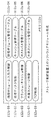
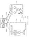
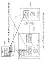
0056 図1は、本発明の方法および装置が適用されるハードウエア構成の例を示す。システムは第1と第2ストレージサブシステム100eおよび100uを含んでおり、それらはストレージエリアネットワーク(SAN)200f、200bのようなネットワークによってホストコンピュータ300および管理運営サーバー400に接続されている。ストレージサブシステム100eおよび100uは、各々ストレージ制御装置110およびディスク装置120を有する。ストレージ制御装置110は、SAN 200fを経由してファイバーチャンネルプロトコルを使用し、ホストコンピュータ300とディスク入出力機能を行う。ディスク装置120は複数のハード・ディスク・ドライブ(HDD)を有する。ストレージ制御装置110はこれらのHDDを組み合わせてRAID(Redundant Arrays of Inexpensive Disks:低価格ディスク冗長アレイ)を構成し、ホストコンピュータ300にボリューム(LU: logical unit)を提供する。これらの機能は図2および図6に示されるアプリケーションプログラムによって実行される。
FIG. 1 shows an example of a hardware configuration to which the method and apparatus of the present invention is applied. The system includes first and
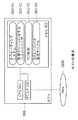
0057 図2は、第2のストレージサブシステム100uに内蔵するメモリ112uのソフトウェアモジュール構成を示す。このモジュールは論理ボリューム入出力制御112u−01、物理ディスク制御112u−02、フラッシュ/キャッシュ制御112u−03、外部ストレージ制御112u−07、FCP(ファイバーチャンネルプロトコル)制御112u−09、論理ボリューム管理テーブル112u−04、キャッシュ管理テーブル112u−05、ホストパス管理テーブル112u−06および外部ストレージ管理テーブル112u−08を含んでいる。図6は、第1のストレージサブシステム100eに内蔵するメモリ112eのソフトウェアモジュール構成を示す。このモジュールは、論理ボリューム入出力制御112e−01、物理ディスク制御112e−02、フラッシュ/キャッシュ制御112e−03、論理ボリューム管理テーブル112e−05、キャッシュ管理テーブル112e−06およびホストパス管理テーブル112e−07を含んでいる。
FIG. 2 shows a software module configuration of the
0058 図3は、論理ボリューム管理テーブル112u−04の例を示す。“WWPN”欄は、第2のストレージサブシステム100u上のHBAのWWPNを表わす。“LUN”欄はストレージサブシステム上のLU番号を表わす。“VOL#”欄はストレージサブシステム上のボリュームを表わす。図3に見るように、ホストコンピュータ300がWWPN_1にアクセスする時、LUN0およびLUN1に接続することができる。
FIG. 3 shows an example of the logical volume management table 112u-04. The “WWPN” column represents the WWPN of the HBA on the
0059 図4は、ホストパス管理テーブル112u−06の例を示す。第2のストレージサブシステム100uは、LUNセキュリティのために、ホスト(イニシエータWWPN)のWWPNを使用してのLUへのアクセスを制限される。
FIG. 4 shows an example of the host path management table 112u-06. The
0060 図5は、外部ストレージ管理テーブル112u−08の例を示す。外部ストレージはストレージ仮想化技術を有している。ストレージサブシステムAおよびBは互いに接続されている。ホストコンピュータがストレージサブシステムA上の仮想LUに接続する場合、ストレージサブシステムB上のLUにも、ストレージサブシステムA上の仮想LUとストレージサブシステムB上のLUとを接続することにより到達することができる。“WWPN”欄は、ストレージサブシステムA上のHBAのWWPNを表わす。“LUN”欄はストレージサブシステムA上の(仮想)LUNを表わす。“イニシエータWWPN”欄は、ストレージサブシステムBに接続するためのストレージサブシステムA上のHBAのイニシエータWWPNを表わす。“ターゲットWWPN”欄はストレージサブシステムB上のHBAのWWPNを表す。最後の“LUN”欄は、ストレージサブシステムA上の仮想LUNに関連するストレージサブシステムB上のLUNを表す。 FIG. 5 shows an example of the external storage management table 112u-08. The external storage has storage virtualization technology. Storage subsystems A and B are connected to each other. When the host computer connects to the virtual LU on the storage subsystem A, the LU on the storage subsystem B is also reached by connecting the virtual LU on the storage subsystem A and the LU on the storage subsystem B. be able to. The “WWPN” column represents the WWPN of the HBA on the storage subsystem A. The “LUN” column represents a (virtual) LUN on the storage subsystem A. The “initiator WWPN” column represents the initiator WWPN of the HBA on the storage subsystem A for connection to the storage subsystem B. The “Target WWPN” column represents the WWPN of the HBA on the storage subsystem B. The last “LUN” column represents the LUN on the storage subsystem B related to the virtual LUN on the storage subsystem A.
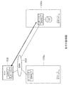
0061 図7は、ホストコンピュータ300の典型的な構成を示す。ホストコンピュータ300は、FC I/F303を経由してSAN 200fに接続し、ストレージサブシステムl00eおよび100uに入出力接続をしている。ホストコンピュータ300はCPU301およびメモリ302を有する。図示された実施例では、メモリ302はオペレーティングシステム302−01、仮想コンピュータ用ハイパーバイザ302−02、FCP制御302−03およびストレージパス管理テーブル302−04を格納する。ホストコンピュータは、実体のあるホストであっても良いし、仮想コンピュータのような仮想ホストでもよい。
FIG. 7 shows a typical configuration of the
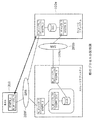
0062 図8は、管理運営サーバー400の典型的な構成を示す。管理運営サーバー400は、イーサーネット(登録商標)I/F403およびネットワークLANによってストレージサブシステム100e、100uおよびホストコンピュータ300に接続している。管理運営サーバー400は、ストレージサブシステム100e、100uおよびホストコンピュータ300を制御し移行プロセスを実行する。管理運営サーバー400はCPU401、およびオペレーティングシステム402−01および移行制御402−02を格納するメモリ402を有する。
FIG. 8 shows a typical configuration of the
0063 2.NPIVおよび明示的入出力停止を使用する移行 0063 2. Migration using NPIV and explicit I / O suspension
0064 図9a−9eはNPIVおよび明示的入出力停止を使用する移行プロセスの例を示す。NPIVはN_ポートID仮想化(N_Port ID Virtualization)を表わし、HBAが仮想WWPNを持つことを可能にする。この実施例では、入出力パスの再構成を必要としない移行のためにストレージサブシステムにNPIVを適用している。 Figures 9a-9e show an example of a migration process using NPIV and explicit I / O suspension. NPIV stands for N_Port ID Virtualization and allows the HBA to have a virtual WWPN. In this embodiment, NPIV is applied to the storage subsystem for migration that does not require I / O path reconfiguration.
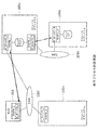
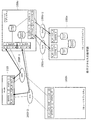
0065 図9aは、移行プロセスの第1の状態を示す。ホストコンピュータ310(実体のあるホストあるいはバーチャルホストのどちらでも良い)は、SAN 200fを経由してファイバーチャンネルを使用し、第1のストレージサブシステム100eに接続している。ホストコンピュータ310は、SAN 200fに接続されたWWPN_1、N_ポートID_1を有する。第1のストレージサブシステムは、LU1とSAN 200fに接続されているWWPN_2,N_ポートID_2を有する。第2のストレージサブシステムは、SAN 200fに接続されたWWPN_3、N_ポートID_3を有する。
FIG. 9a shows the first state of the migration process. The host computer 310 (which may be a real host or a virtual host) is connected to the
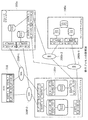
0066 図9bは、移行プロセスの第2の状態を示す。第2のストレージサブシステム100uはVLU1に対し仮想WWPNを定義する(WWPN_2(V))、ここにおいて、この仮想WWPNは第1のストレージサブシステム100eの(物理的)WWPN(WWPN_2)と同じである。第2のストレージサブシステム100uはさらに、ストレージ仮想化機能を使用して、第1のストレージサブシステム100e上のLU1に接続するようにイニシエータポート(SAN 200bに接続されているWWPN_4、N_ポートID_4)を定義する。ストレージ仮想化機能の例は、米国特許番号7,003,634および7,228,380にある。次に、ホストコンピュータ310は、第1のストレージサブシステム100eに対する入出力命令を停止する。その後、第2のストレージサブシステム100uは仮想WWPNおよびイニシエータポートを活性化する。これは、第2のストレージサブシステム100uが仮想WWPN(WWPN_2(V)、N_ポートID_2X)に対し新しいN_ポートIDを得るためにFDISCメッセージをSAN 200fに送信することを可能にする。
FIG. 9b shows the second state of the migration process. The
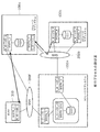
0067 図9cは、移行プロセスの最終状態を示す。第1のストレージサブシステム100eはWWPN_2を動作停止とし、SAN 200bのSNS(Simple Name Server)のデータベースを更新する。(第1のストレージサブシステム100eのWWPN_2は削除される)。次に、ホストコンピュータ310は以前と同じWWPN(WWPN_2)を使用して、入出力命令を再開する。今回は、WWPN_2は第2のストレージサブシステム100uの所有となる。このプロセスは、ホストコンピュータ310が入出力命令を古いストレージサブシステム100eから新規のストレージサブシステム100uに切り換えることを可能にする。
FIG. 9c shows the final state of the migration process. The
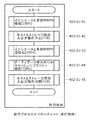
0068 例えば、図10、11、12および13は、管理運営サーバー400、ストレージサブシステム100e、100uおよびホストコンピュータ310によって実行される移行プロセスのフローチャートを示す。
For example, FIGS. 10, 11, 12 and 13 show flowcharts of a migration process executed by the
0069 図10において、移行制御は次のように行われる。まず、第2のストレージサブシステム100uの中にイニシエータおよび仮想WWPNを構成し(402−01−01)、ホストコンピュータ310と第1のストレージサブシステム100eの間の入出力命令を停止し(402−01−02)、イニシエータおよび第2のストレージサブシステム100uの中の仮想WWPNを活性化し(402−01−03)、ホストコンピュータ310と第2のストレージサブシステム100uの間の入出力命令を再開する(402−01−04)。
In FIG. 10, the transition control is performed as follows. First, an initiator and a virtual WWPN are configured in the
0070 図11において、移行プロセスのための外部ストレージ制御は以下のステップを含む。すなわち、外部ストレージ100eに接続するため第2のストレージサブシステム100uにイニシエータポートを構成し(112u−07−01)、第2のストレージサブシステム100uの中の仮想WWPNとして物理ポートに外部ストレージ100eのWWPNを加え、第2のストレージサブシステム100uに仮想LUを構成する(これは外部ストレージ100eのLUに対応付けられる)。
In FIG. 11, external storage control for the migration process includes the following steps: That is, an initiator port is configured in the
0071 図12において、移行のための外部ストレージ制御はイニシエータおよび仮想WWPNの活性化を必要とする。プロセスは以下のステップを含む。すなわち、第2のストレージサブシステム100uによるSANへの物理的な接続性をチェックし(112u−07−11)、外部ストレージ100eのLUに第2のストレージサブシステム100uの仮想LUの仮想WWPNを対応させ(112u−07−12)、FCファブリックへFCIF113uを通してFDISCメッセージを送ることにより、第2のストレージサブシステム100uの中の仮想WWPNを活性化する(112u−07―13)。
In FIG. 12, external storage control for migration requires activation of the initiator and virtual WWPN. The process includes the following steps. That is, the physical connectivity to the SAN by the
0072 図13において、移行プロセスのためのFCP制御は、SANへのFDISCを行ない(112u−09−01)、追加のN_ポートIDを得て(112e−09−02)、登録のためSANファブリックへのPLOGIを行うこと(112e−09−03)を含む。 In FIG. 13, the FCP control for the migration process performs FDISC to SAN (112u-09-01), obtains additional N_Port ID (112e-09-02), and enters SAN fabric for registration Performing PLOGI (112e-09-03).
0073 図9dおよび9eは、図9a−9cの移行プロセスの状態の別の例を示す。図9dにおいては、第2のストレージサブシステム100uはそのイニシエータポートの中でホストコンピュータ310と同じ仮想WWPN(WWPN_1(V))を定義する。これは、図9cの状態と比較して、第1のストレージサブシステム100eがLUNマスキングを再構成しないことを可能にする。図9eにおいては、第2のストレージサブシステム100uの採用の後、第1のストレージサブシステム100eの中のLU1のデータは、第2のストレージサブシステム100uのLU1に移動させることができる。これで、第1のストレージサブシステム100eを取り外すことが可能となる。
FIGS. 9d and 9e show another example of the state of the migration process of FIGS. 9a-9c. In FIG. 9d, the
0074 本発明のこの実施例はストレージサブシステムの移行のみに限定されているわけではなく、ポートの移行にも使用することができる。(例えばストレージサブシステム上でポート−Aからポート−Bへ入出力を移動する) This embodiment of the invention is not limited to storage subsystem migration, but can also be used for port migration. (For example, move input / output from port-A to port-B on the storage subsystem)
0075 3.多重パスの場合のNPIVおよび明示的入出力停止を使用する移行 0075 3. Migration using NPIV and explicit I / O suspension for multiple paths
0076 図14a−14cは、ホストコンピュータ310とストレージサブシステム100e、100uの間に複数の入出力パスを備えた場合の、NPIVおよび明示的入出力停止を使用した移行プロセスの例を示す。
FIGS. 14a-14c show examples of migration processes using NPIV and explicit I / O suspension when multiple I / O paths are provided between the
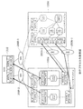
0077 図14aは、移行プロセスの第1の状態を示す。ホストコンピュータ310は、SAN 200f−1およびSAN 200f−2によって第1のストレージサブシステム100eへの複数の入出力パスを持っている(この例はパス−Aおよびパス−Bを示す)。ホストコンピュータ310はSAN 200f−2に接続されたWWPN_1、N_ポートID_1、およびSAN 200f−1に接続されたWWPN_2、N_ポート1D_2を有する。第1のストレージサブシステム100eは、SAN 200f−2に接続されたWWPN_3、N_ポートID_3、およびSAN 200f−1に接続されたWWPN_4、N_ポートID_4を有する。第2のストレージサブシステム100uはSAN 200f−2に接続されたWWPN_5、N_ポートID_5、およびSAN 200f−1に接続されたWWPN_6、N_ポートID_6を有する。第1のストレージサブシステム100eにおいては、LDEV1は、複数のLUからアクセスすることができるボリュームを意味する。この技術は複数の入出力パスを行うために使用される。
FIG. 14a shows the first state of the migration process. The
0078 図14bは、移行プロセスの第2の状態を示す。第2のストレージサブシステム100uは、多重パス用の多重の仮想WWPNおよびイニシエータを定義する。第2のストレージサブシステム100uは、SAN 200b−1に接続されているイニシエータWWPN_8、N_ポートID_8を備えたVLU1に対しWWPN_3(V)、N_ポートID_3Xを有し、また、SAN 200b−2に接続されているイニシエータWWPN_7、N_ポートID_7を備えたVLU2に対しWWPN_4(V)、N_ポートID_4xを有する。ホストコンピュータ310は第1のストレージサブシステム100eとの入出力パス(パス−Aおよびパス−B)を停止する。
FIG. 14b shows the second state of the migration process. The
0079 図14cは、移行プロセスの最終状態を示す。第2のストレージサブシステム100uはその仮想WWPNを活性化し、SAN 200b−1およびSAN 200b−2を経由してストレージ仮想化機能によって第1のストレージサブシステム100eに接続する。次に、ホストコンピュータ310は同じWWPNを使用して、複数の入出力命令パスを再開する。今や、そのWWPNは第2のストレージサブシステム100uによって所有さている。
FIG. 14c shows the final state of the migration process. The
0080 図15は、複数の入出力パスを備えて、NPIVおよび明示的入出力停止を使用した移行プロセスの処理フローの例を示す。プロセスは次のステップを含む、すなわち、第2のストレージサブシステム100uにイニシエータおよび仮想WWPNをパスAに対し構成する(402−01−11)、同じ構成をパス_Bに対しても行う(402−01−12)、ホストコンピュータ310と第1のストレージサブシステム100eの間の入出力を停止する(402−01−13)、第2のストレージサブシステム100uの中のイニシエータおよび仮想WWPNをパスAに対し活性化する(402−01−14)、同じ活性化をパスBに対しても行う(402−01−15)、ホストコンピュータ310と第2のストレージサブシステム100uの間の入出力を再開する(402−01−16)。
FIG. 15 shows an example of the process flow of the migration process with multiple I / O paths and using NPIV and explicit I / O suspension. The process includes the following steps: configure the initiator and virtual WWPN for path A in the
0081 4.NPIVおよびRSCNを使用する移行 0081 4. Migration using NPIV and RSCN
0082 図16a−16cは、NPIVとRSCNを使用する移行プロセスの例を示す。RSCNは Registered State Change Notification(登録状態変更通知)を表わし、ファブリックSNSデータベースが変更された場合(例えばディスク(ターゲット装置)を加えるまたは取り去る、新規のゾーンを作るなど)、SANファブリック中のファイバーチャンネルノードに通知する。この実施例は、入出力パスの再構成を必要としない移行のために、ストレージサブシステムにRSCNとNPIVを適用する。 FIGS. 16a-16c show an example of a migration process using NPIV and RSCN. RSCN stands for Registered State Change Notification and when the fabric SNS database is changed (for example, adding or removing a disk (target device), creating a new zone, etc.), a Fiber Channel node in the SAN fabric Notify This embodiment applies RSCN and NPIV to the storage subsystem for migration that does not require I / O path reconfiguration.
0083 図16aは、移行プロセスの第1の状態を示す。ホストコンピュータ310は、ファイバーチャンネルを用いSAN 200fを通して、第1のストレージサブシステム100eに接続する。ホストコンピュータ310は、SAN 200fに接続されたWWPN_1、N_ポートID_1を有する。第1のストレージサブシステム100eは、SAN 200fに接続されたWWPN_2、N_ポートID_2を有する。第2のストレージサブシステム100uは、SAN 200f接続されたWWPN_3、N_ポートID_3を有する。
FIG. 16a shows the first state of the migration process. The
0084 図16bは、移行プロセスの第2の状態を示す。第2のストレージサブシステム100uは、第1のストレージサブシステム100eの(物理的)WWPNと同じである仮想WWPN (WWPN_2(V))を定義し、さらにSAN 200bを通してストレージ仮想化機能を使用し、第1のストレージサブシステム100e上のLU1に接続するようにイニシエータポート(WWPN_4、N_ポートID_4)を定義する。そうするために、第1のストレージサブシステム100eは、LU1に接続されている別のWWPN(WWPN_5)を定義する。次に、第2のストレージサブシステム100uは仮想WWPNおよびイニシエータポートを活性化させる。これにより、第2のストレージサブシステム100uが、仮想WWPN(WWPN_2(V)、N_ポートID_2X)に対して新規のN_ポートIDを得るためにSAN 200fにFDISCメッセージを送ることが可能となる。
FIG. 16b shows the second state of the migration process. The
0085 図16cは、移行プロセスの最終状態を示す。第2のストレージサブシステム100uの中の仮想WWPNは、SAN 200fのSNSデータベースへ登録される。これは、SAN 200fがホストコンピュータ310にRSCNを送ることを可能にする。ホストコンピュータ310は第1のストレージサブシステム100eから入出力動作完了の後にログアウトのためにLOGOを送る。次に、ホストコンピュータ310は、SNSデータベースの現状の情報を得る。また、SNSデータベースは、第2のストレージサブシステム100u上のWWPN_2に新規のN_ポートID(WWPN_2(V)、N_ポートID_2X)を準備する。この仕組みにより、ホストコンピュータ310が入出力命令を古いストレージサブシステム100eから新規のストレージサブシステム100uへ切り換えることが可能となる。新規のN_ポートIDを識別するために、このシステムは以下のように動作する:
(1) SNSデータベースはWWPN_2に対し2つのN_ポートIDを持つ。この場合、ホストコンピュータ310はより新しいN_ポートIDを選択する。
(2) SNSデータベースはWWPN_2に対し2つのN_ポートIDを持つ。第1のRSCNが送られると、ホストコンピュータ310はその入出力動作を完了する。その後に、ホストコンピュータ310は、第1のストレージサブシステム100eがそのWWPN_2を無効にした時送られる別のRSCNを待つ。
(3) SNSデータベースは、WWPN_2に対し1つのN_ポートIDを保持するのみであり、より新しいものを選ぶ。
FIG. 16c shows the final state of the migration process. The virtual WWPN in the
(1) The SNS database has two N_Port IDs for WWPN_2. In this case, the
(2) The SNS database has two N_Port IDs for WWPN_2. When the first RSCN is sent, the
(3) The SNS database only holds one N_Port ID for WWPN_2, and selects a newer one.
0086 図17−19は、例として、管理運営サーバー400、ストレージサブシステム100e、100uおよびホストコンピュータ310によって実行される移行プロセスの処理フローの例を示す。
FIGS. 17-19 show an example of the processing flow of the migration process executed by the
0087 図17では、移行制御は、第1のストレージサブシステム100eの中へのパス構成(402−01−21)、第2のストレージサブシステム100uにおけるイニシエータおよび仮想WWPNの構成(402−01−22)、第2のストレージサブシステム100uの中のイニシエータおよび仮想WWPNの活性化(402−01−23)、ホストコンピュータ310のストレージ入出力の切り換え(402−01−24)によって行なわれる。
In FIG. 17, the migration control includes path configuration into the
0088 図18においては、移行プロセスの論理ボリューム入出力制御は、第2のストレージサブシステム100uによってSANへの接続性をチェックし(112e−01−01)、第2のストレージサブシステム100uの仮想LUの仮想WWPNを外部ストレージサブシステム100eのLUに対応づけ(112e−01−02)、外部ストレージ100eに対しLUNセキュリティをセットする(112e−01−03)、ステップを有する。
In FIG. 18, the logical volume input / output control of the migration process checks the connectivity to the SAN by the
0089 図19においては、移行プロセスのためのFCP制御は、ホストコンピュータ310によってSANからRSCNを受け取り(302−02−01)、ホストコンピュータ310により動作している入出力を完了させて第1のストレージサブシステム100eからのLOGOを受け取る(302−02−02)、SANのSNSをチェックして第2のストレージサブシステム100uのために新規パス情報を得る(302−02−03)、次に新規パス情報を使用して、第2のストレージサブシステム100uへのPLOGIを行う(302−02−04)ステップを有する。
In FIG. 19, in the FCP control for the migration process, the
0090 この実施例は、前述の図9dおよび9eと同じように、代替の例を持つことも出来る。第2のストレージサブシステム100uはそのイニシエータポート(WWPN_1(V))にホストコンピュータ310と同じ仮想WWPNを定義する。これは、第1のストレージサブシステム100eがLUNマスキングを再構成しないことを可能にする。第2のストレージサブシステム100uを選択した後、第1のストレージサブシステム100eの中のLU1のデータは、第2のストレージサブシステム100uのLU1に移動させることができる。これで、第1のストレージサブシステム100eを撤去することが可能となる。本発明のこの実施例はストレージサブシステムの移行のみに限定されるものではなく、ポートの移行(例えばストレージサブシステム上で入出力をポート−Aからポート−Bへ移動する)に使用することができる。
This embodiment can have alternative examples, similar to FIGS. 9d and 9e described above. The
0091 5.多重パスでNPIVおよびRSCNを使用する移行 0091 5. Migration using NPIV and RSCN with multiple paths
0092 図20a−20dは、ホストコンピュータ310とストレージサブシステム100e、100uの間に複数の入出力パスを備えていて、NPIVおよびRSCNを使用する移行プロセスの例を示す。
FIGS. 20a-20d show an example of a migration process with multiple input / output paths between the
0093 図20aは、移行プロセスの第1の状態を示す。ホストコンピュータ310は、SAN 200f−1およびSAN 200f−2を通して第1のストレージサブシステム100eへの複数の入出力パスを持っている(この例ではパス−Aおよびパス−Bを示す)。ホストコンピュータ310は、SAN 200f−2に接続されたWWPN_1、N_ポートID_1、およびSAN 200f−1に接続されたWWPN_2、N_ポートID_2を有する。第1のストレージサブシステム100eは、SAN 200f−2に接続された、LU1に対するWWPN_3、N_ポートID_3、およびSAN 200f−1に接続された、LU2に対するWWPN_4、N_ポートID_4を有する。第2のストレージサブシステム100uはSAN 200f−2に接続されたWWPN_5、N_ポートID_5、およびSAN 200f−1に接続されたWWPN_6、N_ポートID_6を有する。
FIG. 20a shows the first state of the migration process. The
0094 図20bは、移行プロセスの第2の状態を示す。第2のストレージサブシステム100uは、パス−Aのための仮想WWPNおよびイニシエータを定義する。WWPN_5については、第2のストレージサブシステム100uが、SAN 200b−1に接続されたイニシエータWWPN_8、N_ポートID_8を備えたVLU1に対しWWPN_3(V)を有する。第1のストレージサブシステム100eは、LU3およびSAN 200b−1に接続されたWWPN_9、N_ポートID_9を定義する。
FIG. 20b shows the second state of the migration process. The
0095 図20cは、移行プロセスの第3の状態を示す。ホストコンピュータ310は、パス−Aの入出力パスをRSCNにより切り換える(第1のストレージサブシステム100eのWWPN_3へのSAN 200f−2によるパスから、第2のストレージサブシステム100uのWWPN_3(V)へのSAN 200f−2によるパスへ)。第2のストレージサブシステム100uはその仮想WWPN_3(V)を活性化し、第1のストレージサブシステム100eのWWPN_9、N_ポートID_9に、SAN 200b−1を通して、ストレージ仮想化機能によって接続する。これは、第2のストレージサブシステム100uが仮想WWPN(WWPN_3(V)、N_ポートID_3X)のために新規のN_ポートIDを得るためにSAN 200f−2にFDISCメッセージを送ることを可能にする。さらに、第2のストレージサブシステムI00uは、パス−Bのための仮想WWPNおよびイニシエータを定義する。WWPN_6については、第2のストレージサブシステム100uが、SAN 200b−2に接続されているイニシエータWWPN_7、N_ポートID_7を備えたVLU2に対してWWPN_4(V)を有する。第1のストレージサブシステム100eは、LU4およびSAN 200b−2に接続されているWWPN_10、N_ポートID_10を定義する。
FIG. 20c shows the third state of the migration process. The
0096 図20dは、移行プロセスの最終状態を示す。ホストコンピュータ310はRSCNによってパス−Bの入出力パスを切り換える(第1のストレージサブシステム100eのWWPN_4へのSAN 200f−1を通ったパスから、第2のストレージサブシステム100uのWWPN_4(V)へのSAN 200f−1を通ったパスへ)。第2のストレージサブシステム100uは、その仮想のWWPN_4(V)を活性化し、SAN 200b−2を通してストレージ仮想化機能により第1のストレージサブシステム100eのWWPN_10、N_ポートID_10に接続する。これは、第2のストレージサブシステム100uが仮想WWPN(WWPN_4(V)、N_ポートID_4x)のために新規のN_ポートIDを得るためにSAN 200f−1にFDISCメッセージを送ることを可能にする。その結果、ホストコンピュータ310は同じWWPNを使用する複数の入出力パスを持つこととなり、そのWWPNは今や第2のストレージサブシステム100uの所有となる。
FIG. 20d shows the final state of the migration process. The
0097 図21は、複数の入出力パスを備え、NPIVおよびRSCNを使用した移行プロセスの処理フローの例を示す。プロセスは以下のステップを有する。すなわち、パス−Aおよびパス−Bに対し第1のストレージサブシステム100eにパス構成を行う(402−01−31)、パス−Aおよびパス−Bに対し第2のストレージサブシステム100uにイニシエータ、および仮想WWPNを構成する(402−01−32)、パス−Aに対し第2のストレージサブシステム100uのイニシエータおよび仮想WWPNを活性化する(402−01−33)、パスAに対するホストコンピュータ310のストレージ入出力を切り換える(402−01−34)、パス−Bに対し第2のストレージサブシステム100uのイニシエータおよび仮想WWPNを活性化する(402−01−35)、またパス−Bに対しホストコンピュータ310のストレージ入出力を切り換える(402−01−36)。
FIG. 21 shows an example of a processing flow of a migration process that includes a plurality of input / output paths and uses NPIV and RSCN. The process has the following steps. That is, the path configuration is performed in the
0098 6.ストレージ仮想化環境におけるNPIVおよび明示的入出力停止を用いる移行 0098 6. Migration using NPIV and explicit I / O suspension in a storage virtualization environment
0099 図22a−eは、ストレージ仮想化環境の中でNPIVおよび明示的入出力停止を使用する移行プロセスの例を示す。この場合、第2のストレージサブシステム100uは、ホストコンピュータ310および第1のストレージサブシステム100eに接続している。第2のストレージサブシステム100uを第3のストレージサブシステムl00nに取り替えるために、この実施例では、入出力パスの再構成を要しない移行のためストレージサブシステムにNPIVを適用する。
FIG. 22a-e shows an example of a migration process using NPIV and explicit I / O suspension in a storage virtualization environment. In this case, the
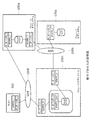
0100 図22aは、移行プロセスの第1の状態を示す。ホストコンピュータ310はSAN 200fを通してファイバーチャンネルを使用して、第2のストレージサブシステム100uに接続している、また、第2のストレージサブシステム100uは、ストレージ仮想化機能を使用して、ホストコンピュータ310にLU1を提供するために第1のストレージサブシステム100eに接続している。ホストコンピュータ310は、SAN 200fに接続されたWWPN_1、N_ポートID_1を有する。第2のストレージサブシステムは、VLU1とSAN 200fに接続されたWWPN_2、N_ポートID_2を有する。さらに、第2のストレージサブシステムはVLU1およびSAN 200bに接続されたWWPN_3、N_ポートID_3を有する。第1のストレージサブシステムは、LU1およびSAN 200bに接続されたWWPN_4、N_ポートID_4を有する。第3のストレージサブシステムはSANに200fに接続されたWWPN_5、N_ポートID_5を有する。
FIG. 22a shows the first state of the migration process. The
0101 図22bは、移行プロセスの第2の状態を示す。第3のストレージサブシステム100nは、第2のストレージサブシステム100uの(物理的)WWPN(WWPN_2)と同じである仮想WWPN(WWPN_2(V))をVLU1に対して定義する。さらに、第3のストレージサブシステム100nは、SAN 200bを通してストレージ仮想化機能を使用し、第1のストレージサブシステム100e上のLU1に接続するためにイニシエータポート(WWPN_6、N_ポートID_6)を定義する。次に、ホストコンピュータ310は、第1のストレージサブシステム100eに対し入出力動作を停止する。第3のストレージサブシステム100nは仮想WWPNおよびイニシエータポートを活性化する。これにより、第3のストレージサブシステム100nが、仮想WWPN(WWPN_2(V)、N_ポートID_2X)のために新規のN_ポートIDを得るべくSAN 200fにFDISCメッセージを送ることが可能となる。
FIG. 22b shows the second state of the migration process. The
0102 図22cは、移行プロセスの最終状態を示す。第2のストレージサブシステム100uはWWPN_2を停止し、SAN 200fのSNSデータベースを更新する。(第2のストレージシステム100uのWWPN_2は削除される)。次に、ホストコンピュータ310は以前と同じWWPN(WWPN_2)を使用して、入出力を再開する。この時、WWPN_2は、第3のストレージサブシステム100nに所有されている。このプロセスは、ホストコンピュータ310が入出力を古いストレージサブシステム100uから新しいストレージサブシステム100nへ切り換えることを可能にする。
FIG. 22c shows the final state of the migration process. The
0103 図23は、例として、管理運営サーバー400、ストレージサブシステム100e、100u、100n、およびホストコンピュータ310によって実行される移行プロセスの処理フローの例を示す。図23では、移行制御は次によって行われる。第3のストレージサブシステム100nの中にイニシエータおよび仮想WWPNを構成する(402−01−41)、ホストコンピュータ310と第1のストレージサブシステム100e間の入出力をストレージ仮想化環境で停止する(402−01−42)、第3のストレージサブシステム100nの中のイニシエータおよび仮想WWPNを活性化する(402−01−43)、第2のストレージサブシステム100uの中のダーティデータを取り除くためにキャッシュにフラッシング動作をする(402−01−44)、そして、ホストコンピュータ310と第1のストレージサブシステム100eの間の入出力を再開する(402−01−45)。これは、ストレージ仮想化環境の中で行われ、第3のストレージサブシステム100nが第2のストレージサブシステム100uを置換する。
FIG. 23 shows an example of the processing flow of the migration process executed by the
0104 図22dおよび22eは、移行プロセスの状態の別の例を示す。図22dにおいては、第3のストレージサブシステム100nは第2のストレージサブシステム100uと同じ仮想WWPNをイニシエータポート(WWPN_3(V))に定義する。これは、図22cの状態と比較して、第1のストレージサブシステム100eがLUNマスキングを再構成しないことを許容する。図22eでは、第3のストレージサブシステム100nを選択した後、第1のストレージサブシステム100eの中のLU1のデータは、第3のストレージサブシステム100nのLU1に移動させることができる。これで、第1のストレージサブシステム100eを取り去ることが可能となる。
Figures 22d and 22e show another example of the status of the migration process. In FIG. 22d, the
0105 本発明のこの実施例は、ストレージサブシステム移行のみに限定されものではなく、ポートの移行(例えば、ストレージサブシステム上でポート−Aからポート−Bへと入出力を移動させる)に使用することもできる。 This embodiment of the present invention is not limited to storage subsystem migration only, but is used for port migration (eg, moving input / output from port-A to port-B on the storage subsystem). You can also
0106 7.ストレージ仮想化環境、多重パスにおけるNPIVおよび明示的入出力停止を使用する移行 0106 7. Migration using storage virtualization environment, NPIV in multiple paths and explicit I / O suspension
0107 図24a−24cは、ストレージ仮想化環境の中で、ホストコンピュータ310とストレージサブシステム100e、100u、100nの間の複数の入出力パスを備えていて、NPIVおよび明示的入出力停止を使用した移行プロセスの例を示す。
24a-24c have multiple I / O paths between the
0108 図24aは、移行プロセスの第1の状態を示す。ホストコンピュータ310は、SAN 200f−1およびSAN 200f−2によって(この例はパス−Aおよびパス−Bを示す)第2のストレージサブシステム100uへの複数の入出力パスを持っている。また、第2のストレージサブシステム100uはストレージ仮想化機能を使用して、第1のストレージサブシステム100eに接続している。ホストコンピュータ310はSAN 200f−2に接続されたWWPN_1、N_ポートID_1、およびSAN 200f−1に接続されたWWPN_2、N_ポートID_2を有する。第2のストレージサブシステム100uは、VLU1およびSAN 200f−2に接続されたWWPN_3、N_ポートID_3、およびVLU2およびSAN 200f−1に接続されたWWPN_4、N_ポートID_4を有する。第2のストレージサブシステム100uは、さらに、VLU1およびSAN 200b−1に接続されたWWPN_5、N_ポートID_5、および、VLU2およびSAN 200b−2に接続されたWWPN_6、N_ポートID_6を有する。第1のストレージサブシステム100eはLU1およびSAN 200b−1に接続されたWWPN_7、N_ポートID_7、およびLU2およびSAN 200b−2に接続されたWWPN_8、N_ポートID_8を有する。第3のストレージサブシステム100nは、SAN 200f−2に接続されたWWPN_9、N_ポートID_9およびSAN 200f−1に接続したWWPN_10、N_ポートID_10を有する。
FIG. 24a shows the first state of the migration process. The
0109 図24bは、移行プロセスの第2の状態を示す。第3のストレージサブシステム100nは、多重パスに対し多重の仮想WWPNおよびイニシエータを定義する。第3のストレージサブシステム100nは、SAN 200b−1に接続されたイニシエータWWPN_11、N__ポートID_11を備えたVLU1に対し、WWPN_3(V)、N__ポートID_3Xを持っており、SAN 200b−2に接続されたイニシエータWWPN_12、N_ポートID_12を備えたVLU2に対しWWPN_4(V)、N_ポートID_4Xを持っている。ホストコンピュータ310は、ストレージ仮想化環境の中で、第1のストレージサブシステム100eとの入出力パス(パス−Aおよびパス−B)を停止する。
FIG. 24b shows the second state of the migration process. The
0110 図24cは、移行プロセスの最終状態を示す。第3のストレージサブシステム100nはその仮想WWPNを活性化し、SAN 200b−1およびSAN 200b−2を通してストレージ仮想化機能によって第1のストレージサブシステム100eに接続する。次に、ホストコンピュータ310は、今や、第3のストレージサブシステム100nによって所有されている同じWWPNを使用して、ストレージ仮想化環境の中で複数の入出力パスを再開する。
FIG. 24c shows the final state of the migration process. The
0111 図25は、複数の入出力パスを備えたストレージ仮想化環境の中で、NPIVおよび明示的入出力停止を使用した移行プロセスの処理フローの例を示す。プロセスは次のステップを有する。第3のストレージサブシステム100nに、パスAのため(402−01−51)とパスBのため(402−01−52)にイニシエータおよび仮想WWPNを構成する。ホストコンピュータ310と、第1のストレージサブシステム100eの間の入出力を、ストレージ仮想化環境の中で停止し(402−01−53)、第3のストレージサブシステム100nの中で、イニシエータおよび仮想WWPNをパスAに対し活性化し(402−01−54)、同じくパスBのために活性化する(402−01−55)。第2のストレージサブシステム100uの中のダーティデータを取り除くためにキャッシュにフラッシング動作を行う(402−01−56)、そして、ストレージ仮想化環境の中、ホストコンピュータ310と、第1のストレージサブシステム100eの間の入出力を再開する。ここにおいて第3のストレージサブシステム100nが第2のストレージサブシステム100uを置換する(402−01−57)。
FIG. 25 shows an example of the process flow of the migration process using NPIV and explicit I / O suspension in a storage virtualization environment with multiple I / O paths. The process has the following steps. In the
0112 8.ストレージ仮想化環境においてNPIVおよびRSCNを使用する移行 0112 8. Migration using NPIV and RSCN in a storage virtualization environment
0113 図26a−26cは、ストレージ仮想化環境の中でNPIVとRSCNを使用した移行プロセスの例を示す。この場合、第2のストレージサブシステム100uは、ホストコンピュータ310および第1のストレージサブシステム100eに接続している。第2のストレージサブシステム100uを第3のストレージサブシステム100nで置換するために、この実施例では、ストレージ仮想化環境の中で、入出力パスの再構成を必要としない移行のために、ストレージサブシステムにRSCNとNPIVを適用する。
FIGS. 26a-26c illustrate an example migration process using NPIV and RSCN in a storage virtualization environment. In this case, the
0114 図26aは、移行プロセスの第1の状態を示す。ホストコンピュータ310はSAN 200fによってファイバーチャンネルを使用して、第2のストレージサブシステム100uに接続され、また、ストレージ仮想化機能を使用してホストコンピュータ310にLU1を提供するために、第2のストレージサブシステム100uは第1のストレージサブシステム100eに接続される。ホストコンピュータ310は、SAN 200fに接続されたWWPN_1、N_ポートID_1を有する。第2のストレージサブシステム100uはSAN 200fに接続されたWWPN_2、N_ポートID_2を有する。第2のストレージサブシステム100uは、さらに、VLU1およびSAN 200bに接続されたWWPN_3、N_ポートID_3を有する。第1のストレージサブシステム100eは、SAN 200bに接続されたWWPN_4、N_ポートID_4を有する。第3のストレージサブシステム100nはSAN 200f接続されたWWPN_5、N_ポートID_5を有する。
FIG. 26a shows the first state of the migration process. The
0115 図26bは、移行プロセスの第2の状態を示す。第3のストレージサブシステム100nは、第2のストレージサブシステム100uの(物理的)WWPNと同じ仮想WWPNを(WWPN_2(V))と定義する。それは、さらにSAN 200bを通してストレージ仮想化機能を用い、第1のストレージサブシステム100e上のLU1に接続するイニシエータポート(WWPN_6、N_ポートID_6)を定義する。そうするために、第1のストレージサブシステム100eは、LU1に接続される別のWWPN(WWPN_7)を定義する。次に、第3のストレージサブシステム100nは仮想WWPNおよびイニシエータポートを活性化する。これにより、第3のストレージサブシステム100nが、SAN 200fへ、仮想WWPN (WWPN_2(V)、N_ポートID_2X)のために新規のN_ポートIDを得るために、FDISCメッセージを送ることが可能となる。
FIG. 26b shows the second state of the migration process. The
0116 図26cは、移行プロセスの最終状態を示す。第3のストレージサブシステム100nの仮想WWPNは、SAN 200fのSNSデータベースへ登録される。これにより、SAN 200fがホストコンピュータ310にRSCNを送ることが可能となる。ホストコンピュータ310は第2のストレージサブシステム100uからログアウトするために入出力動作完了後にLOGOを送出する。次に、ホストコンピュータ310は、SNSデータベースの現在の情報を入手する。また、SNSデータベースは、第3のストレージサブシステム100n上のWWPN_2に新規のN_ポートID(WWPN_2(V)、N_ポートID_2X)を提供する。この仕組みは、ホストコンピュータ310が入出力接続を古いストレージサブシステム100uから新規のストレージサブシステム100nに切り換えることを可能とする。新規のN_ポートIDを識別するために、このシステムは以下のように動く:
(1) SNSデータベースはWWPN_2に対し2つのN_ポートIDを持つ。
この場合、ホストコンピュータ310はより新しいN_ポートIDを選ぶ。
(2) SNSデータベースはWWPN_2に対し2つのN_ポートIDを持つ。第1のRSCNが送られる時に、ホストコンピュータ310はその入出力を完了する。その後に、ホストコンピュータ310は、第2のストレージサブシステム100uがそのWWPN_2を無効にした時に送られる別のRSCNを待つ。
(3) SNSデータベースはWWPN_2に対しただ1つのN_ポートIDを保持することとなり、より新しいものを選ぶこととなる。
FIG. 26c shows the final state of the migration process. The virtual WWPN of the
(1) The SNS database has two N_Port IDs for WWPN_2.
In this case, the
(2) The SNS database has two N_Port IDs for WWPN_2. When the first RSCN is sent, the
(3) The SNS database will hold only one N_Port ID for WWPN_2 and will choose a newer one.
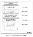
0117 例えば、図27は、管理運営サーバー400、ストレージサブシステム100e、100uおよびホストコンピュータ310によって実行される移行プロセスの処理フローの例を示す。移行制御は次によって実行される。第1のストレージサブシステム100eにパスを構成する(402−01−61)、第3のストレージサブシステム100nにイニシエータおよび仮想WWPNを構成する(402−01−62)、第2のストレージサブシステム100uの中のこのパスに対する入出力キャッシュを無効にし(402−01−63)、第3のストレージサブシステム100nの中のイニシエータおよび仮想WWPNを活性化し(402−01−64)、ホストコンピュータ310のストレージ入出力を切り換える(402−01−65)。
For example, FIG. 27 shows an example of the processing flow of the migration process executed by the
0118 この実施例は、前述した図9dおよび9eと同じ様に状態の代替例を持ち得る。第3のストレージサブシステム100nはそのイニシエータポートに第1のストレージサブシステム100eと同じ仮想WWPN (WWPN_2(V))を定義する。これは、第1のストレージサブシステム100eがLUNマスキングを再構成しないことを可能にする。第3のストレージサブシステム100nの選択の後、第1のストレージサブシステム100eの中のLU1のデータを、第3のストレージサブシステム100nのLU1に移動させることができる。これにより、第1のストレージサブシステム100eを取り外すことが可能となる。本発明のこの実施例はストレージサブシステム移行のみに限定されるものではなく、ポートの移行にも使用することができる(例えばストレージサブシステム上のポート−Aからポート−Bへの入出力の移動)。
[0118] This embodiment may have a state alternative as in Figures 9d and 9e described above. The
0119 9.ストレージ仮想化環境、多重パスでのNPIVおよびRSCNを使用する移行 0119 9. Storage virtualization environment, migration using NPIV and RSCN with multiple paths
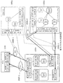
0120 図28a−28dは、ストレージ仮想化環境の中で、ホストコンピュータ310とストレージサブシステム100e、100u、100nの間に複数の入出力パスを備え、NPIVおよびRSCNを使用する移行プロセスの例を示す。
FIGS. 28a-28d show an example of a migration process with multiple I / O paths between the
0121 図28aは、移行プロセスの第1の状態を示す。ホストコンピュータ310は、SAN 200f−1およびSAN 200f−2を通して第2のストレージサブシステム100uへの複数の入出力パスを有する。また、第2のストレージサブシステム100uは、ストレージ仮想化機能を使用して、第1のストレージサブシステム100eに接続している(この例はパス−Aおよびパス−Bを示す)。ホストコンピュータ310は、SAN 200f−2に接続されたWWPN_1、N_ポートID_1、およびSAN 200f−1に接続されたWWPN_2、N_ポートID_2を有する。第2のストレージサブシステム100uは、VLU1およびSAN 200f−2に接続されたWWPN_3、N_ポートID_3、およびVLU2およびSAN 200f−1に接続されたWWPN_4、N_ポートID_4を有する。第2のストレージサブシステム100uは、さらに、VLU1およびSAN 200b−1に接続されたWWPN_5、N_ポートID_5、およびVLU2およびSAN 200b−2に接続されたWWPN_6、N_ポートID_6を有する。第1のストレージサブシステム100eには、LU1およびSAN 200b−1に接続されたWWPN_7、N_ポートID_7、およびLU2およびSAN 200b−2に接続されたWWPN_8、N_ポートID_8を有する。
FIG. 28a shows the first state of the migration process. The
0122 図28bは、移行プロセスの第2の状態を示す。第3のストレージサブシステム100nは、パス−Aに対し仮想WWPNおよびイニシエータを定義する。WWPN_9については、第3のストレージサブシステム100nは、SAN 200b−1に接続されたイニシエータWWPN_11、N_ポートID_11を備えたVLU1に対しWWPN_3(V)を有する。第1のストレージサブシステム100eはLU3に接続されたWWPN_13、N_ポートID_13を定義する。
FIG. 28b shows the second state of the migration process. The
0123 図28cは、移行プロセスの第3の状態を示す。ホストコンピュータ310は、RSCNによりパス−Aの入出力パスを切り換える(SAN 200f−2を経由する第2のストレージサブシステム100uの中のWWPN_3へのパスから、SAN 200f−2を経由する第3のストレージサブシステム100nのWWPN_9へ)。第3のストレージサブシステム100nは、自身の仮想WWPN_3(V)を活性化し、SAN 200b−1を通し、ストレージ仮想化機能によって、第1のストレージサブシステム100eのWWPN_13、N_ポートID_13に接続する。これにより、第3のストレージサブシステム100nが、仮想WWPN(WWPN_3(V)、N_ポートID_3X)に対して新規のN_ポートIDを得るために、SAN 200f−2にFDISCメッセージを送るこがと可能となる。さらに、第3のストレージサブシステム100nは、パス−Bに対し仮想WWPNおよびイニシエータを定義する。WWPN_10については、第3のストレージサブシステム100nは、SAN 200b−2に接続されているイニシエータWWPN_12、N_ポートID_12を備えたVLU2に対し、WWPN_4(V)を有する。第1のストレージサブシステム100eはLU4に接続されるWWPN_14、NポートID_14を定義する。
FIG. 28c shows the third state of the migration process. The
0124 図28dは、移行プロセスの最終状態を示す。ホストコンピュータ310は、パス−Bの入出力パスをRSCNにより切替える(SAN 200f−1を経由する第2のストレージサブシステム100uの中のWWPN_4へのパスから、SAN 200f−1を経由する第3のストレージサブシステム100nの中のWWPN_10へのパスへ)。第3のストレージサブシステム100nは、自身の仮想WWPN_4(V)を活性化し、SAN 200b−2を通してストレージ仮想化機能により第1のストレージサブシステム100eのWWPN_14、N_ポートID_14に接続する。これにより、第3のストレージサブシステム100nが、仮想WWPN(WWPN_4(V)、NポートID_4X)に対し新規のN_ポートIDを得るためにSAN 200f−1にFDISCメッセージを送ることが可能となる。その結果、ホストコンピュータ310は、今や第3のストレージサブシステム100nによって所有されている同じWWPNを使用して、ストレージ仮想化環境の中で複数の入出力パスを持つ事となる。
FIG. 28d shows the final state of the migration process. The
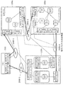
0125 図29は、ストレージ仮想化環境の中で複数の入出力パスを備え、NPIVおよびRSCNを使用した移行プロセスの処理フローの例を示す。プロセスは以下のステップを有する。第1のストレージサブシステム100eの中にパス−Aのためのパスの構成(402−01−71)、第3のストレージサブシステム100nに、パス−Aのためのイニシエータおよび仮想WWPNの構成(402−01−72)、パス−Aのための入出力キャッシュの動作を停止(402−01−73)、パス−Aに対し第3のストレージサブシステム100nの中のイニシエータおよび仮想WWPN活性化(402−01−74)、ホストコンピュータ310のパス−Aに対するストレージ入出力の切り換え(402−01−75)、パス−Bに対し第1のストレージサブシステム100eにおけるパスの構成(402−01−76)、パス−Bに対し第3のストレージサブシステム100nにおけるイニシエータおよび仮想VVWPNの構成(402−01−77)、パス−Bに対し入出力キャッシュの動作を停止(402−01−78)、第3のストレージサブシステム100nにおいてイニシエータおよび仮想WWPNをパス−Bに対し活性化(402−01−79)、ホストコンピュータ310のパス−Bに対するストレージ入出力の切り換える(402−01−80)。
FIG. 29 shows an example of a processing flow of a migration process that includes a plurality of input / output paths in a storage virtualization environment and uses NPIV and RSCN. The process has the following steps. Path configuration for path-A (402-01-71) in the
0126 上記は、FC―SAN環境下における本発明の様々な実施例について記述している。本発明は、イーサーネット(登録商標)環境におけるファイバーチャンネル(FCoE)のような異なる環境のもとでも実行され得る。それは、イーサーネット(登録商標)上でFCフレームを送受することを可能にする。FCoEノードはMACアドレスおよびN_ポートIDを持つイーサネット(登録商標)・アダプタを有する。この様に、本発明は特別なカスタマイゼーションなしにFCoE環境下で動作する。 The above describes various embodiments of the present invention in an FC-SAN environment. The present invention may also be implemented under different environments such as Fiber Channel (FCoE) in an Ethernet environment. It makes it possible to send and receive FC frames over Ethernet. The FCoE node has an Ethernet adapter with a MAC address and N_Port ID. In this way, the present invention operates in an FCoE environment without any special customization.
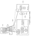
0127 図30は、FCoEフォワーダー(FCF)を使用したFCoEに対しNPIVおよび明示的入出力停止を使用した移行プロセスの例を示す。図9cと比較すると、図30には、イーサーネット(登録商標)を通してMACアドレスMAC_1を有するホストコンピュータ310と通信するMACアドレスMAC_2を備えたFCFがある。FCFは、(ホストコンピュータ310の)FCoEノードおよび(ストレージサブシステムの)FCノードが、互いに通信することを可能にする。FCFの1つの例はシスコネクサス5000装置である。ホストコンピュータ310と第2のストレージサブシステム100uはWWPNおよびN_ポートIDを使用して、入出力接続を確立する。ホストコンピュータ310およびFCFは、互いに通信するのにMACアドレスを使用する。一方、ホストコンピュータ310およびストレージサブシステムは各WWPNおよびN_ポートIDをトンネリング技術の場合と同様にして知ることができる。
FIG. 30 shows an example of a migration process using NPIV and explicit I / O suspension for FCoE using FCoE Forwarder (FCF). Compared to FIG. 9c, FIG. 30 has an FCF with a MAC address MAC_2 that communicates with a
0128 図31は、NPIVおよび明示的入出力停止を、ネイティブFCoEストレージシステムに対し使用した移行プロセスの例を示す。FCFは必要ではない。代わりに、ホストコンピュータ310およびストレージサブシステム100e、100uは、互いと通信するためにMACアドレスを使用する。第1のストレージシステムはMACアドレスMAC_2を持つ。第2のストレージシステムはポートN_ポートID_3に対応するMAC_3を持つ。MAC_4はイニシエータポートN_ポートID_4に対応し、MAC_5は仮想ポートN_ポートID_2Xに対応する。仮想ポートN_ポートID_2Xに対する専用のMAC数であるMAC_5の代わりに、MAC_3を使用する通信を第2のストレージサブシステム100uに使用することができることは注目すべきことである。
FIG. 31 shows an example of a migration process using NPIV and explicit I / O suspension for a native FCoE storage system. FCF is not necessary. Instead, the
0129 以上の説明から、本発明が、入出力パスの再構成を必要としないストレージサブシステム移行のための方法、装置およびコンピュータ読取り可能な媒体上に格納されたプログラムを提供していることは明白である。さらに、この明細書において、特定の実施例を図示し記述してあるが、同業者においては、同じ目的を達成すると意図されるどのような構成も、ここに開示された特定の実施例の代わりに用いられ得ることは認識されよう。この開示は、本発明の全ての修正あるいは変化を包含するように意図されている。また、次の請求項の中で使用される用語は、本発明を明細書に示された特定の実施例に限定するように解釈されるべきでないことは理解されよう。さらに正確に言えば、発明の範囲はすべて以下の請求項によって決定されることとなるが、それは、そのような請求項に権利がある総ての範囲の等価物の全領域に対して、請求項解釈の確立している理論に従って解釈されるべきことである。 From the above description, it is apparent that the present invention provides a method, apparatus and program stored on a computer readable medium for storage subsystem migration that does not require I / O path reconfiguration. It is. Further, although specific embodiments have been illustrated and described herein, any configuration intended to accomplish the same purpose by those skilled in the art can be substituted for the specific embodiments disclosed herein. It will be appreciated that it can be used for: This disclosure is intended to cover all modifications or variations of the invention. It will also be understood that the terms used in the following claims should not be construed to limit the invention to the specific embodiments illustrated in the specification. More precisely, the scope of the invention will all be determined by the following claims, which are claimed for the full scope of equivalents of the full scope of such claims. It should be interpreted according to the established theory of term interpretation.
Claims (22)
前記第1のストレージサブシステムは、前記第1のストレージサブシステム中の第1のボリュームが前記コンピュータ装置との入出力接続をしている第1のポートに対し、固有の第1のポート名を持ち、
前記第2のストレージサブシステムは、前記第1のストレージサブシステム中の前記第1のボリュームに対応付けた第1の仮想ボリュームと、該第1の仮想ボリュームに対応付けた、前記第1のストレージサブシステム中の前記第1のポートの前記第1のポート名と同一の第1の仮想ポート名を有する第1の仮想ポートとを定義し、
前記第2のストレージサブシステムは、前記ネットワークへ前記第1の仮想ポートを登録するために、前記第1の仮想ボリュームに対応した前記第1の仮想ポートを活性化するように構成され、
前記コンピュータ装置は、前記第1の仮想ポートの活性化の後に、前記第1のボリュームに対する入出力(I/O)接続を、前記第1のストレージサブシステムから前記第2のストレージサブシステムへ、前記第2のストレージサブシステム上の前記第1の仮想ポート名を使用して前記ネットワークによって切り換えるように構成される、
ことを特徴とするコンピュータシステム。 A first storage subsystem connected by a network, a second storage subsystem, and a computer device;
The first storage subsystem assigns a unique first port name to the first port in which the first volume in the first storage subsystem has input / output connection with the computer device. Have
The second storage subsystem includes a first virtual volume associated with the first volume in the first storage subsystem, and the first storage associated with the first virtual volume. Defining a first virtual port having a first virtual port name identical to the first port name of the first port in the subsystem;
The second storage subsystem is configured to activate the first virtual port corresponding to the first virtual volume to register the first virtual port to the network;
After the activation of the first virtual port, the computer device transfers an input / output (I / O) connection to the first volume from the first storage subsystem to the second storage subsystem. Configured to switch by the network using the first virtual port name on the second storage subsystem;
A computer system characterized by that.
前記第2のストレージサブシステムは、前記第1のストレージサブシステム中の前記第2のボリュームに対応付けた第2の仮想ボリュームと、該第2の仮想ボリュームに対応付けた、前記第1のストレージサブシステム中の前記第2のポートの前記第2のポート名と同一の第2の仮想ポート名を持つ第2の仮想ポートとを定義し、
前記第2のストレージサブシステムは、前記追加されたネットワークへ前記第2の仮想ポートを登録するために、前記第2の仮想ボリュームに対応した前記第2の仮想ポートを活性化するように構成され、
前記コンピュータ装置は、前記第1の仮想ポートの活性化の後に、前記第2のボリュームに対する入出力接続を、前記第1のストレージサブシステムから前記第2のストレージサブシステムへ、前記第2のストレージサブシステム上の前記第2の仮想ポート名を使用して、前記追加のネットワークによって切り換えるように構成される、
ことを特徴とする請求項1によるコンピュータシステム。 The first storage subsystem has another unique second port name for the second port, through which the second volume in the first storage subsystem is added to the network By making an input / output connection with the computer device,
The second storage subsystem includes a second virtual volume associated with the second volume in the first storage subsystem, and the first storage associated with the second virtual volume. Defining a second virtual port having a second virtual port name identical to the second port name of the second port in the subsystem;
The second storage subsystem is configured to activate the second virtual port corresponding to the second virtual volume in order to register the second virtual port in the added network. ,
After the activation of the first virtual port, the computer device transfers an input / output connection to the second volume from the first storage subsystem to the second storage subsystem. Configured to switch by the additional network using the second virtual port name on a subsystem;
A computer system according to claim 1.
ことを特徴とする請求項1によるコンピュータシステム。 The second storage subsystem is configured such that a first initiator port is defined to connect the first virtual volume to the first volume in the first storage subsystem; One initiator port has the same virtual port name as the port name of the computer device connected to the network for input / output (I / O) of the first volume in the first storage subsystem have,
A computer system according to claim 1.
前記第2のストレージサブシステムが、前記第1の仮想ポートの活性化の後に、前記第1の仮想ポート名に対して第1のN_ポートIDを受け取る、
ことを特徴とする請求項1によるコンピュータシステム。 Prior to the activation of the first virtual port corresponding to the first virtual volume of the second storage subsystem, the computer apparatus performs input / output (I / O) with the first storage subsystem. Configured to stop operation)
The second storage subsystem receives a first N_Port ID for the first virtual port name after activation of the first virtual port;
A computer system according to claim 1.
ことを特徴とする請求項4によるコンピュータシステム。 The second storage subsystem is configured such that a first initiator port is defined to connect the first virtual volume to the first volume in the first storage subsystem; One initiator port is the same virtual port name as the port name of the computer device connected to the network for input / output (I / O) connection of the first volume in the first storage subsystem have,
A computer system according to claim 4.
前記第2のストレージサブシステムの前記第1の仮想ボリュームに対応した前記第1の仮想ポートの活性化の後、前記コンピュータ装置は、前記ネットワークから、前記第2のストレージサブシステムの前記第1の仮想ボリュームに対応した前記第1の仮想ポート名に対して、RSCN(Registered State Change Notification)と第1のN_ポートIDを受け取り、前記第1のボリュームのため入出力接続を、前記第1のストレージサブシステムから前記第2のストレージサブシステムへ切り換える、
ことを特徴とする請求項1によるコンピュータシステム。 The first storage subsystem has a first additional port having a first additional port name, through which the first volume in the first storage subsystem is the second An input / output (I / O) connection with the first virtual volume of the storage subsystem;
After activation of the first virtual port corresponding to the first virtual volume of the second storage subsystem, the computing device removes the first of the second storage subsystem from the network. For the first virtual port name corresponding to the virtual volume, an RSCN (Registered State Change Notification) and a first N_Port ID are received, and an input / output connection for the first volume is made to the first storage. Switching from the subsystem to the second storage subsystem;
A computer system according to claim 1.
ことを特徴とする請求項6によるコンピュータシステム。 After the computer device receives the RSCN from the network, the computer device logs out of the first storage subsystem;
A computer system according to claim 6.
ことを特徴とする請求項1によるコンピュータシステム。 After the computer device switches input / output (I / O) connection for the first volume from the first storage subsystem to the second storage subsystem, the second storage subsystem Performs data migration of the first volume,
A computer system according to claim 1.
前記第1のストレージサブシステムは、前記第1のストレージサブシステム中の第1のボリュームが前記コンピュータ装置との入出力(I/O)接続をしている第1のポートに対し、固有の第1のポート名を持ち、
前記第2のストレージサブシステム(SS2)は、前記第1のストレージサブシステム中の前記第1のボリュームと対応する第1のSS2仮想ボリュームと、該第1のSS2仮想ボリュームの前記ネットワークによる前記コンピュータ装置との入出力(I/O)接続のための第1のSS2ポート名を持つ第1のSS2ポートとを含み、
前記第3のストレージサブシステム(SS3)は、前記第1のストレージサブシステム中の前記第1のボリュームに対応付けられている第1のSS3仮想ボリュームと、該第1のSS3仮想ボリュームに対応付けられている第1のSS3仮想ポートとを定義し、該第1のSS3仮想ポートは、前記第2のストレージサブシステム中の前記第1のSS2仮想ポートの前記第1のSS2ポート名と同一である第1のSS3仮想ポート名を持ち、
前記第3のストレージサブシステムは、前記ネットワークへ前記第1のSS3仮想ポートを登録するために、前記第1のSS3仮想ボリュームに対応する前記第1のSS3仮想ポートを活性化するように構成され、
前記コンピュータ装置は、前記第1のSS3仮想ポートの活性化の後に、前記第1のボリュームのための入出力(I/O)接続を、前記第2のストレージサブシステムから前記第3のストレージサブシステムへ、前記第3のストレージサブシステムの上で前記第1のSS3仮想ポート名を使用して、前記ネットワークによって切り換えるように構成される、
ことを特徴とするコンピュータシステム。 A first storage subsystem connected by a network, a second storage subsystem, a third storage subsystem, and a computer device;
The first storage subsystem has a unique first to the first port in which the first volume in the first storage subsystem has input / output (I / O) connection with the computer device. With a port name of 1
The second storage subsystem (SS2) includes a first SS2 virtual volume corresponding to the first volume in the first storage subsystem, and the computer by the network of the first SS2 virtual volume. A first SS2 port having a first SS2 port name for input / output (I / O) connection with the device;
The third storage subsystem (SS3) is associated with the first SS3 virtual volume associated with the first volume in the first storage subsystem and the first SS3 virtual volume. A first SS3 virtual port that is identical to the first SS2 port name of the first SS2 virtual port in the second storage subsystem. Have a first SS3 virtual port name,
The third storage subsystem is configured to activate the first SS3 virtual port corresponding to the first SS3 virtual volume to register the first SS3 virtual port with the network. ,
After the activation of the first SS3 virtual port, the computer device makes an input / output (I / O) connection for the first volume from the second storage subsystem to the third storage subsystem. Configured to switch to the system by the network using the first SS3 virtual port name on the third storage subsystem;
A computer system characterized by that.
前記第2のストレージサブシステム(SS2)は、前記第1のストレージサブシステム中の前記第2のボリュームと対応する第2のSS2仮想ボリュームと、第2のSS2ポートとを含み、該第2のSS2ポートは前記追加的なネットワークによる前記コンピュータ装置との前記第2のSS2仮想ボリュームの入出力(I/O)接続のための第2のSS2ポート名を持ち、
前記第3のストレージサブシステム(SS3)は、前記第1のストレージサブシステム中の前記第2のボリュームに対応付けられている第2のSS3仮想ボリュームと、該第2のSS3仮想ボリュームに対応付けられている第2のSS3仮想ポートとを定義し、該第2のSS3仮想ポートは、前記第2のストレージサブシステム中の前記第2のSS2仮想ポートの前記第2のSS2ポート名と同一である第2のSS3仮想ポート名を持ち、
前記第3のストレージサブシステムは、前記追加のネットワークへ前記第2のSS3仮想ポートを登録するために、前記第2のSS3仮想ボリュームに対応する前記第2のSS3仮想ポートを活性化するように構成され、
前記コンピュータ装置は、前記第1のSS3仮想ポートの活性化の後に、前記第2のボリュームのための入出力接続を、前記第2のストレージサブシステムから前記第3のストレージサブシステムへ、前記第3のストレージサブシステムの上で前記第2のSS3仮想ポート名を使用して、前記ネットワークによって切り換えるように構成される、
ことを特徴とする請求項9によるコンピュータシステム。 The first storage subsystem has another unique second port name for the second port, and a second network in the first storage subsystem through an additional network through the second port. Are in input / output (I / O) connection with the computer device,
The second storage subsystem (SS2) includes a second SS2 virtual volume corresponding to the second volume in the first storage subsystem, and a second SS2 port, and the second storage subsystem (SS2) The SS2 port has a second SS2 port name for input / output (I / O) connection of the second SS2 virtual volume with the computer device via the additional network;
The third storage subsystem (SS3) is associated with the second SS3 virtual volume associated with the second volume in the first storage subsystem and the second SS3 virtual volume. And the second SS3 virtual port is identical to the second SS2 port name of the second SS2 virtual port in the second storage subsystem. Have a second SS3 virtual port name,
The third storage subsystem activates the second SS3 virtual port corresponding to the second SS3 virtual volume to register the second SS3 virtual port to the additional network. Configured,
After the activation of the first SS3 virtual port, the computer apparatus transfers an input / output connection for the second volume from the second storage subsystem to the third storage subsystem. Configured to switch by the network using the second SS3 virtual port name on three storage subsystems;
A computer system according to claim 9.
前記第3のストレージサブシステムは、第1のSS3イニシエータポートが、前記第1のSS3仮想ボリュームを前記第1のストレージサブシステム中の前記第1のボリュームに接続する様定義するように構成され、該第1のSS3イニシエータポートは、前記第2のストレージサブシステム中の前記追加された第1のSS2ポートの前記追加された第1のSS2ポートの名と同一の仮想ポート名を持っている、
ことを特徴とする請求項9によるコンピュータシステム。 The second storage subsystem (SS2) provides an additional first SS2 port name for input / output (I / O) connection of the first SS2 virtual volume with the first storage subsystem. Including an additional first SS2 port with
The third storage subsystem is configured to define a first SS3 initiator port to connect the first SS3 virtual volume to the first volume in the first storage subsystem; The first SS3 initiator port has the same virtual port name as the name of the added first SS2 port of the added first SS2 port in the second storage subsystem.
A computer system according to claim 9.
前記第3のストレージサブシステムが、前記第1のSS3仮想ポートの活性化の後に、前記第1のSS3仮想ポート名に対して第1のSS3N_ポートIDを受け取る、
ことを特徴とする請求項9によるコンピュータシステム。 Prior to the activation of the first SS3 virtual port corresponding to the first SS3 virtual volume of the third storage subsystem, the computer device inputs / outputs (I) to the first storage subsystem. / O) configured to stop operation,
The third storage subsystem receives a first SS3N_Port ID for the first SS3 virtual port name after activation of the first SS3 virtual port;
A computer system according to claim 9.
前記第3のストレージサブシステムの前記第1のSS3仮想ボリュームに対応した前記第1のSS3仮想ポートの活性化の後、前記コンピュータ装置は、前記ネットワークから、前記第3のストレージサブシステムの前記第1のSS3仮想ボリュームに対応した前記第1のSS3仮想ポート名に対して、RSCN(Registered State Change Notification)と第1のN_ポートIDを受け取り、前記第1のボリュームのための入出力接続を、前記第1のストレージサブシステムから前記第3のストレージサブシステムへ切り換える、
ことを特徴とする請求項9によるコンピュータシステム。 The first storage subsystem has a first additional port having a first additional port name, and the first volume in the first storage subsystem is passed through the first additional port. Making an input / output (I / O) connection with the first SS3 virtual volume of the third storage subsystem;
After activation of the first SS3 virtual port corresponding to the first SS3 virtual volume of the third storage subsystem, the computing device removes the first of the third storage subsystem from the network. An RSCN (Registered State Change Notification) and a first N_Port ID are received for the first SS3 virtual port name corresponding to one SS3 virtual volume, and an input / output connection for the first volume is established. Switching from the first storage subsystem to the third storage subsystem;
A computer system according to claim 9.
ことを特徴とする請求項9によるコンピュータシステム。 After the computer device switches input / output (I / O) connection for the first volume from the second storage subsystem to the third storage subsystem, the third storage subsystem Performs data migration of the first volume,
A computer system according to claim 9.
前記第1のストレージサブシステムは、前記第1のストレージサブシステム中の第1のボリュームが前記コンピュータ装置との入出力(I/O)接続をしている第1のポートに対し、固有の第1のポート名を持つ、コンピュータシステムにおいて、
前記第2のストレージサブシステムにおいて、前記第1のストレージサブシステム中の前記第1のボリュームに対応する第1の仮想ボリュームと、該第1の仮想ボリュームに対応し、前記第1のストレージサブシステム中の前記第1のポートの前記第1のポート名と同一の第1の仮想ポート名を持つ第1の仮想ポートと、を定義するステップと、
前記第1の仮想ポートを前記ネットワークへ登録するために、前記第2のストレージサブシステムの前記第1の仮想ボリュームに対応する前記第1の仮想ポートを活性化するステップと、
前記第1の仮想ポートの活性化の後に、前記第2のストレージサブシステム上で前記第1の仮想ポート名を使用し、前記ネットワークによって前記第1のストレージサブシステムから前記第2のストレージサブシステムへ、前記第1のボリュームに対する前記コンピュータ装置の入出力(I/O)接続を切り換えるステップと、
からなることを特徴とする、入出力パスの再構成を必要としないストレージサブシステム移行のための方法。 A first storage subsystem connected by a network, a second storage subsystem, and a computer device;
The first storage subsystem has a unique first to the first port in which the first volume in the first storage subsystem has input / output (I / O) connection with the computer device. In a computer system with a port name of 1
In the second storage subsystem, a first virtual volume corresponding to the first volume in the first storage subsystem, a first virtual volume corresponding to the first virtual volume, and the first storage subsystem Defining a first virtual port having a first virtual port name identical to the first port name of the first port therein;
Activating the first virtual port corresponding to the first virtual volume of the second storage subsystem to register the first virtual port with the network;
After the activation of the first virtual port, the first virtual port name is used on the second storage subsystem, and the second storage subsystem from the first storage subsystem by the network Switching the input / output (I / O) connection of the computer device to the first volume;
A method for storage subsystem migration that does not require I / O path reconfiguration.
ことを特徴とする請求項15による方法。 Furthermore, in the second storage subsystem, the same port name as the port of the computer device connected to the network for input / output connection of the first volume in the first storage subsystem. Defining a first initiator port having a virtual port name to connect the first virtual volume to the first volume in the first storage subsystem;
Method according to claim 15, characterized in that
前記第1の仮想ポートの活性化の後に、前記第2のストレージサブシステムに前記第1の仮想ポート名に対し第1のN_ポートIDを提供するステップと、
を更に含むことを特徴とする請求項15による方法。 Stopping the input / output operation of the computer device with the first storage subsystem prior to the activation of the first virtual port corresponding to the first virtual volume of the second storage subsystem. When,
Providing a first N_Port ID for the first virtual port name to the second storage subsystem after activation of the first virtual port;
16. The method according to claim 15, further comprising:
前記第2のストレージサブシステムの前記第1の仮想ボリュームに対応した前記第1の仮想ポートの活性化の後、前記第2のストレージサブシステムの前記第1の仮想ボリュームに対応した前記第1の仮想ポート名に対して、RSCN(Registered State Change Notification)と第1のN_ポートIDを、前記コンピュータ装置へ準備するステップと、
前記第1のボリュームに対する前記コンピュータ装置の入出力(I/O)接続を、前記第1のストレージサブシステムから前記第2のストレージサブシステムへ切り換えるステップと、
を更に含むことを特徴とする請求項15による方法。 The first storage subsystem has an input / output (I / O) connection between the first volume in the first storage subsystem and the first virtual volume of the second storage subsystem. And having a first additional port with a first additional port name,
After activating the first virtual port corresponding to the first virtual volume of the second storage subsystem, the first corresponding to the first virtual volume of the second storage subsystem Preparing an RSCN (Registered State Change Notification) and a first N_Port ID for the virtual port name in the computer device;
Switching input / output (I / O) connections of the computer device to the first volume from the first storage subsystem to the second storage subsystem;
16. The method according to claim 15, further comprising:
前記第1のストレージサブシステムは、前記第1のストレージサブシステム中の第1のボリュームが前記コンピュータ装置との入出力(I/O)接続をしている第1のポートに対し、固有の第1のポート名を持ち、
前記第2のストレージサブシステム(SS2)は、前記第1のストレージサブシステム中の前記第1のボリュームに対応する第1のSS2仮想ボリュームと、前記ネットワークによって前記コンピュータ装置との前記第1のSS2仮想ボリュームの入出力(I/O)接続のための第1のSS2ポート名を有する第1のSS2ポートと、を含むコンピュータシステムにおいて、
前記第3のストレージサブシステム(SS3)において、前記第1のストレージサブシステム中の前記第1のボリュームに対応付けられている第1のSS3仮想ボリュームと、該第1のSS3仮想ボリュームに対応付けられていて、前記第2のストレージサブシステム中の前記第1のSS2仮想ポートの前記第1のSS2ポート名と同一である第1のSS3仮想ポート名を持つ、第1のSS3仮想ポートと、を定義するステップと、
前記第1のSS3仮想ポートを前記ネットワークへ登録するために、前記第3のストレージサブシステムの前記第1のSS3仮想ボリュームに対応付けられた、前記第1のSS3仮想ポートを活性化するステップと、
前記第1のSS3仮想ポートの活性化の後、前記コンピュータ装置の前記第1のボリュームに対する入出力(I/O)接続を、前記第2のストレージサブシステムから前記第3のストレージサブシステムへ、前記ネットワークにより、前記第3のストレージサブシステムの前記第1のSS3仮想ポート名を用いて切り換えるステップと、
を含むことを特徴とする、入出力パスの再構成を必要としないストレージサブシステム移行のための方法。 A first storage subsystem connected by a network, a second storage subsystem, a third storage subsystem, and a computer device;
The first storage subsystem has a unique first to the first port in which the first volume in the first storage subsystem has input / output (I / O) connection with the computer device. With a port name of 1
The second storage subsystem (SS2) includes a first SS2 virtual volume corresponding to the first volume in the first storage subsystem, and the first SS2 with the computer device via the network. A computer system comprising: a first SS2 port having a first SS2 port name for input / output (I / O) connection of a virtual volume;
In the third storage subsystem (SS3), the first SS3 virtual volume associated with the first volume in the first storage subsystem is associated with the first SS3 virtual volume. A first SS3 virtual port having a first SS3 virtual port name that is identical to the first SS2 port name of the first SS2 virtual port in the second storage subsystem; A step of defining
Activating the first SS3 virtual port associated with the first SS3 virtual volume of the third storage subsystem to register the first SS3 virtual port with the network; ,
After activation of the first SS3 virtual port, an input / output (I / O) connection to the first volume of the computer device is transferred from the second storage subsystem to the third storage subsystem. Switching by the network using the first SS3 virtual port name of the third storage subsystem;
A method for storage subsystem migration that does not require I / O path reconfiguration.
前記第3のストレージサブシステムにおいて、前記第2のストレージサブシステム中の前記追加の第1のSS2ポートの前記追加の第1のSS2ポート名と同一の仮想ポート名を持っている第1のSS3イニシエータポートを、前記第1のSS3仮想ボリュームを前記第1のストレージサブシステム中の前記第1のボリュームに接続するように定義するステップ、
を更に含むことを特徴とする請求項19による方法。 The second storage subsystem (SS2) has an additional first SS2 port name for input / output (I / O) connection of the first SS2 virtual volume with the first storage subsystem. Including an additional first SS2 port;
In the third storage subsystem, the first SS3 having the same virtual port name as the additional first SS2 port name of the additional first SS2 port in the second storage subsystem Defining an initiator port to connect the first SS3 virtual volume to the first volume in the first storage subsystem;
The method according to claim 19, further comprising:
前記第1のSS3仮想ポートの活性化の後に、前記第3のストレージサブシステムに、前記第1のSS3仮想ポート名に対し第1のSS3 N_ポートIDを提供するステップと、
を更に含むことを特徴とする請求項19による方法。 Prior to the activation of the first SS3 virtual port corresponding to the first SS3 virtual volume of the third storage subsystem, the input / output (I / O) of the computer device with the first storage subsystem O) stopping the operation;
Providing a first SS3 N_Port ID for the first SS3 virtual port name to the third storage subsystem after activation of the first SS3 virtual port;
The method according to claim 19, further comprising:
前記第3のストレージサブシステムの前記第1のSS3仮想ボリュームに対応した前記第1のSS3仮想ポートの活性化の後に、前記コンピュータ装置に、前記第3のストレージサブシステムの前記第1のSS3仮想ボリュームに対応した前記第1のSS3仮想ポート名に対する、RSCN(Registered State Change Notification)と第1のN_ポートIDを提供するステップと、
前記コンピュータ装置の前記第1のボリュームに対する入出力(I/O)接続を、前記第1のストレージサブシステムから前記第3のストレージサブシステムへ切り換えるステップと、
を更に含むことを特徴とする請求項19による方法。 The first storage subsystem includes an input / output (I / O) connection between the first volume in the first storage subsystem and the first SS3 virtual volume of the third storage subsystem. A first additional port having a first additional port name
After the activation of the first SS3 virtual port corresponding to the first SS3 virtual volume of the third storage subsystem, the computer device has the first SS3 virtual of the third storage subsystem. Providing an RSCN (Registered State Change Notification) and a first N_Port ID for the first SS3 virtual port name corresponding to the volume;
Switching input / output (I / O) connection of the computer device to the first volume from the first storage subsystem to the third storage subsystem;
The method according to claim 19, further comprising:
Applications Claiming Priority (2)
| Application Number | Priority Date | Filing Date | Title |
|---|---|---|---|
| US12/232,348 US20100070722A1 (en) | 2008-09-16 | 2008-09-16 | Method and apparatus for storage migration |
| US12/232,348 | 2008-09-16 |
Publications (2)
| Publication Number | Publication Date |
|---|---|
| JP2010073202A true JP2010073202A (en) | 2010-04-02 |
| JP5188478B2 JP5188478B2 (en) | 2013-04-24 |
Family
ID=41416207
Family Applications (1)
| Application Number | Title | Priority Date | Filing Date |
|---|---|---|---|
| JP2009199211A Expired - Fee Related JP5188478B2 (en) | 2008-09-16 | 2009-08-31 | Computer system and method for storage subsystem migration |
Country Status (4)
| Country | Link |
|---|---|
| US (1) | US20100070722A1 (en) |
| EP (1) | EP2163978A3 (en) |
| JP (1) | JP5188478B2 (en) |
| CN (1) | CN101677321B (en) |
Cited By (4)
| Publication number | Priority date | Publication date | Assignee | Title |
|---|---|---|---|---|
| WO2012066594A1 (en) | 2010-11-16 | 2012-05-24 | Hitachi, Ltd. | Computer system and storage migration method |
| US8443160B2 (en) | 2010-08-06 | 2013-05-14 | Hitachi, Ltd. | Computer system and data migration method |
| JP2013210760A (en) * | 2012-03-30 | 2013-10-10 | Nec Corp | Virtual system, switch controller, fiber channel switch, migration method, and migration program |
| JP2014519061A (en) * | 2011-07-22 | 2014-08-07 | 株式会社日立製作所 | Computer system and data migration method thereof |
Families Citing this family (33)
| Publication number | Priority date | Publication date | Assignee | Title |
|---|---|---|---|---|
| US8218571B2 (en) * | 2008-10-24 | 2012-07-10 | International Business Machines Corporation | Fibre channel framing and signaling optional header for ethernet fabric configuration information |
| US8848575B2 (en) * | 2009-02-23 | 2014-09-30 | Brocade Communications Systems, Inc. | High availability and multipathing for fibre channel over ethernet |
| US8463995B2 (en) | 2010-07-16 | 2013-06-11 | Hitachi, Ltd. | Storage control apparatus and storage system comprising multiple storage control apparatuses |
| US8356140B2 (en) | 2010-07-19 | 2013-01-15 | Hitachi, Ltd. | Methods and apparatus for controlling data between storage systems providing different storage functions |
| US8356147B2 (en) | 2010-08-20 | 2013-01-15 | Hitachi, Ltd. | Tiered storage pool management and control for loosely coupled multiple storage environment |
| US8762668B2 (en) * | 2010-11-18 | 2014-06-24 | Hitachi, Ltd. | Multipath switching over multiple storage systems |
| US8645652B2 (en) | 2010-12-17 | 2014-02-04 | International Business Machines Corporation | Concurrently moving storage devices from one adapter pair to another |
| US8806150B2 (en) | 2011-03-28 | 2014-08-12 | Hitachi, Ltd. | Computer system and Fibre Channel migration method |
| US8635391B2 (en) | 2011-05-11 | 2014-01-21 | Hitachi, Ltd. | Systems and methods for eliminating single points of failure for storage subsystems |
| US8656389B2 (en) * | 2011-08-22 | 2014-02-18 | Vmware, Inc. | Virtual port command processing during migration of virtual machine |
| US8868870B1 (en) * | 2012-07-11 | 2014-10-21 | Symantec Corporation | Systems and methods for managing off-host storage migration |
| US9354915B2 (en) * | 2012-07-27 | 2016-05-31 | Hitachi, Ltd. | Method and apparatus of redundant path validation before provisioning |
| CN102970390B (en) * | 2012-11-29 | 2015-06-10 | 杭州华三通信技术有限公司 | Method and device for realizing FC (Fiber Channel) Fabric network intercommunication |
| US20140281306A1 (en) * | 2013-03-14 | 2014-09-18 | Hitachi, Ltd. | Method and apparatus of non-disruptive storage migration |
| US9118984B2 (en) | 2013-03-15 | 2015-08-25 | International Business Machines Corporation | Control plane for integrated switch wavelength division multiplexing |
| US9596192B2 (en) | 2013-03-15 | 2017-03-14 | International Business Machines Corporation | Reliable link layer for control links between network controllers and switches |
| US9444748B2 (en) | 2013-03-15 | 2016-09-13 | International Business Machines Corporation | Scalable flow and congestion control with OpenFlow |
| US9407560B2 (en) | 2013-03-15 | 2016-08-02 | International Business Machines Corporation | Software defined network-based load balancing for physical and virtual networks |
| US9769074B2 (en) | 2013-03-15 | 2017-09-19 | International Business Machines Corporation | Network per-flow rate limiting |
| US9609086B2 (en) | 2013-03-15 | 2017-03-28 | International Business Machines Corporation | Virtual machine mobility using OpenFlow |
| US9104643B2 (en) | 2013-03-15 | 2015-08-11 | International Business Machines Corporation | OpenFlow controller master-slave initialization protocol |
| US9779003B2 (en) | 2013-06-12 | 2017-10-03 | International Business Machines Corporation | Safely mapping and unmapping host SCSI volumes |
| US9274916B2 (en) | 2013-06-12 | 2016-03-01 | International Business Machines Corporation | Unit attention processing in proxy and owner storage systems |
| US8819317B1 (en) | 2013-06-12 | 2014-08-26 | International Business Machines Corporation | Processing input/output requests using proxy and owner storage systems |
| US9769062B2 (en) | 2013-06-12 | 2017-09-19 | International Business Machines Corporation | Load balancing input/output operations between two computers |
| US9940019B2 (en) * | 2013-06-12 | 2018-04-10 | International Business Machines Corporation | Online migration of a logical volume between storage systems |
| US9274989B2 (en) | 2013-06-12 | 2016-03-01 | International Business Machines Corporation | Impersonating SCSI ports through an intermediate proxy |
| US9298752B2 (en) * | 2013-08-26 | 2016-03-29 | Dropbox, Inc. | Facilitating data migration between database clusters while the database continues operating |
| CN105446662B (en) * | 2015-11-24 | 2018-09-21 | 华为技术有限公司 | A kind of cut over method, storage control device and storage device |
| CN105677519B (en) * | 2016-02-25 | 2019-04-30 | 浙江宇视科技有限公司 | A kind of access method and device of resource |
| CN107729190B (en) * | 2017-10-19 | 2021-06-11 | 郑州云海信息技术有限公司 | IO path failover processing method and system |
| US10567308B1 (en) * | 2019-01-28 | 2020-02-18 | Dell Products L.P. | Virtual machine virtual fabric login system |
| US11829602B2 (en) * | 2022-03-16 | 2023-11-28 | Dell Products L.P. | Intelligent path selection in a distributed storage system |
Citations (9)
| Publication number | Priority date | Publication date | Assignee | Title |
|---|---|---|---|---|
| JP2002312127A (en) * | 2001-04-10 | 2002-10-25 | Hitachi Ltd | Storage control device and computer system |
| WO2003085894A1 (en) * | 2002-04-04 | 2003-10-16 | Fujitsu Limited | Apparatus for supporting storage area network system construction, method for supporting the system construction, and program for supporting the system construction |
| JP2003316522A (en) * | 2002-04-26 | 2003-11-07 | Hitachi Ltd | Computer system and method for controlling the same system |
| JP2004227558A (en) * | 2002-11-25 | 2004-08-12 | Hitachi Ltd | Virtual control unit and method for controlling data migration |
| JP2005010872A (en) * | 2003-06-17 | 2005-01-13 | Hitachi Ltd | Device for managing virtual port name |
| JP2006092054A (en) * | 2004-09-22 | 2006-04-06 | Hitachi Ltd | Method for data migration |
| JP2007179529A (en) * | 2005-12-27 | 2007-07-12 | Internatl Business Mach Corp <Ibm> | Data processing system, address allocation method, and computer program (acquiring multiple port addresses from network fabric by fibre channel switch) |
| JP2007310495A (en) * | 2006-05-16 | 2007-11-29 | Hitachi Ltd | Computer system |
| JP2008523520A (en) * | 2004-12-14 | 2008-07-03 | インターナショナル・ビジネス・マシーンズ・コーポレーション | Operating system migration with minimal storage area network reconfiguration |
Family Cites Families (10)
| Publication number | Priority date | Publication date | Assignee | Title |
|---|---|---|---|---|
| US5680640A (en) * | 1995-09-01 | 1997-10-21 | Emc Corporation | System for migrating data by selecting a first or second transfer means based on the status of a data element map initialized to a predetermined state |
| JP3193880B2 (en) * | 1996-12-11 | 2001-07-30 | 株式会社日立製作所 | Data migration method |
| JP3410010B2 (en) * | 1997-12-24 | 2003-05-26 | 株式会社日立製作所 | Subsystem migration method and information processing system |
| US6640291B2 (en) * | 2001-08-10 | 2003-10-28 | Hitachi, Ltd. | Apparatus and method for online data migration with remote copy |
| JP2004110367A (en) * | 2002-09-18 | 2004-04-08 | Hitachi Ltd | Storage system control method, storage control device, and storage system |
| US7263593B2 (en) * | 2002-11-25 | 2007-08-28 | Hitachi, Ltd. | Virtualization controller and data transfer control method |
| US20050050273A1 (en) * | 2003-08-27 | 2005-03-03 | Horn Robert L. | RAID controller architecture with integrated map-and-forward function, virtualization, scalability, and mirror consistency |
| JP4555703B2 (en) * | 2005-02-23 | 2010-10-06 | 株式会社日立製作所 | Area set setting method and network system |
| JP5057741B2 (en) * | 2006-10-12 | 2012-10-24 | 株式会社日立製作所 | Storage device |
| CN101216751B (en) * | 2008-01-21 | 2010-07-14 | 戴葵 | DRAM device with data handling capacity based on distributed memory structure |
-
2008
- 2008-09-16 US US12/232,348 patent/US20100070722A1/en not_active Abandoned
-
2009
- 2009-07-10 EP EP09165257.8A patent/EP2163978A3/en not_active Withdrawn
- 2009-07-30 CN CN200910161295.XA patent/CN101677321B/en active Active
- 2009-08-31 JP JP2009199211A patent/JP5188478B2/en not_active Expired - Fee Related
Patent Citations (9)
| Publication number | Priority date | Publication date | Assignee | Title |
|---|---|---|---|---|
| JP2002312127A (en) * | 2001-04-10 | 2002-10-25 | Hitachi Ltd | Storage control device and computer system |
| WO2003085894A1 (en) * | 2002-04-04 | 2003-10-16 | Fujitsu Limited | Apparatus for supporting storage area network system construction, method for supporting the system construction, and program for supporting the system construction |
| JP2003316522A (en) * | 2002-04-26 | 2003-11-07 | Hitachi Ltd | Computer system and method for controlling the same system |
| JP2004227558A (en) * | 2002-11-25 | 2004-08-12 | Hitachi Ltd | Virtual control unit and method for controlling data migration |
| JP2005010872A (en) * | 2003-06-17 | 2005-01-13 | Hitachi Ltd | Device for managing virtual port name |
| JP2006092054A (en) * | 2004-09-22 | 2006-04-06 | Hitachi Ltd | Method for data migration |
| JP2008523520A (en) * | 2004-12-14 | 2008-07-03 | インターナショナル・ビジネス・マシーンズ・コーポレーション | Operating system migration with minimal storage area network reconfiguration |
| JP2007179529A (en) * | 2005-12-27 | 2007-07-12 | Internatl Business Mach Corp <Ibm> | Data processing system, address allocation method, and computer program (acquiring multiple port addresses from network fabric by fibre channel switch) |
| JP2007310495A (en) * | 2006-05-16 | 2007-11-29 | Hitachi Ltd | Computer system |
Non-Patent Citations (3)
| Title |
|---|
| CSND200400107019; 根岸 伸佳: 'ファイバチャネルによるSAN構築・運用管理読本' NETWORK WORLD 2003 January 第8巻第1号, 20021121, pp.200-203, (株)IDGジャパン * |
| JPN6012034956; 根岸 伸佳: 'ファイバチャネルによるSAN構築・運用管理読本' NETWORK WORLD 2003 January 第8巻第1号, 20021121, pp.200-203, (株)IDGジャパン * |
| JPN7012002576; 横野健二: 'NPIV(N_Port_ID Virtualization)〜サーバ仮想化を支えるファイバチャネル技術の進化〜' Catch the Wind , 20080513, p.8, 東京エレクトロンデバイス株式会社 * |
Cited By (7)
| Publication number | Priority date | Publication date | Assignee | Title |
|---|---|---|---|---|
| US8443160B2 (en) | 2010-08-06 | 2013-05-14 | Hitachi, Ltd. | Computer system and data migration method |
| US8892840B2 (en) | 2010-08-06 | 2014-11-18 | Hitachi, Ltd. | Computer system and data migration method |
| WO2012066594A1 (en) | 2010-11-16 | 2012-05-24 | Hitachi, Ltd. | Computer system and storage migration method |
| US8762669B2 (en) | 2010-11-16 | 2014-06-24 | Hitachi, Ltd. | Computer system and storage migration method utilizing acquired apparatus specific information as virtualization information |
| JP2014519061A (en) * | 2011-07-22 | 2014-08-07 | 株式会社日立製作所 | Computer system and data migration method thereof |
| JP2013210760A (en) * | 2012-03-30 | 2013-10-10 | Nec Corp | Virtual system, switch controller, fiber channel switch, migration method, and migration program |
| US10007536B2 (en) | 2012-03-30 | 2018-06-26 | Nec Corporation | Virtualization system, switch controller, fiber-channel switch, migration method and migration program |
Also Published As
| Publication number | Publication date |
|---|---|
| CN101677321B (en) | 2013-03-27 |
| EP2163978A3 (en) | 2013-04-24 |
| CN101677321A (en) | 2010-03-24 |
| EP2163978A2 (en) | 2010-03-17 |
| JP5188478B2 (en) | 2013-04-24 |
| US20100070722A1 (en) | 2010-03-18 |
Similar Documents
| Publication | Publication Date | Title |
|---|---|---|
| JP5188478B2 (en) | Computer system and method for storage subsystem migration | |
| US8281305B2 (en) | Method and apparatus for resource provisioning | |
| JP6884821B2 (en) | Smart rack architecture for diskless computer systems | |
| US9563380B2 (en) | Zoning of devices in a storage area network with LUN masking/mapping | |
| US9766833B2 (en) | Method and apparatus of storage volume migration in cooperation with takeover of storage area network configuration | |
| US7711979B2 (en) | Method and apparatus for flexible access to storage facilities | |
| EP2339447A2 (en) | Method and apparatus for I/O path switching | |
| JP4965743B2 (en) | Retention of storage area network (“SAN”) access during operating system migration | |
| TWI581589B (en) | Iscsi boot parameter deployment system and iscsi boot parameter deployment method | |
| JP2008523520A (en) | Operating system migration with minimal storage area network reconfiguration | |
| US20100235592A1 (en) | Date volume migration with migration log confirmation | |
| US10229085B2 (en) | Fibre channel hardware card port assignment and management method for port names | |
| US20110276728A1 (en) | Method and apparatus for storage i/o path configuration | |
| US11093144B1 (en) | Non-disruptive transformation of a logical storage device from a first access protocol to a second access protocol | |
| US9164880B2 (en) | Method and apparatus for offloading storage workload | |
| US9027019B2 (en) | Storage drive virtualization | |
| US20150347057A1 (en) | Storage area network emulator | |
| TW201321987A (en) | Method and system to enable pre-boot executable environment operating system install using switch in scalable direct attached storage environment | |
| JP6398417B2 (en) | Storage device, storage system, and storage control program | |
| US10180926B2 (en) | Controlling data storage devices across multiple servers |
Legal Events
| Date | Code | Title | Description |
|---|---|---|---|
| A621 | Written request for application examination |
Free format text: JAPANESE INTERMEDIATE CODE: A621 Effective date: 20110708 |
|
| A977 | Report on retrieval |
Free format text: JAPANESE INTERMEDIATE CODE: A971007 Effective date: 20120704 |
|
| A131 | Notification of reasons for refusal |
Free format text: JAPANESE INTERMEDIATE CODE: A131 Effective date: 20120710 |
|
| A521 | Request for written amendment filed |
Free format text: JAPANESE INTERMEDIATE CODE: A523 Effective date: 20120903 |
|
| TRDD | Decision of grant or rejection written | ||
| A01 | Written decision to grant a patent or to grant a registration (utility model) |
Free format text: JAPANESE INTERMEDIATE CODE: A01 Effective date: 20121225 |
|
| A61 | First payment of annual fees (during grant procedure) |
Free format text: JAPANESE INTERMEDIATE CODE: A61 Effective date: 20130122 |
|
| FPAY | Renewal fee payment (event date is renewal date of database) |
Free format text: PAYMENT UNTIL: 20160201 Year of fee payment: 3 |
|
| R150 | Certificate of patent or registration of utility model |
Free format text: JAPANESE INTERMEDIATE CODE: R150 |
|
| LAPS | Cancellation because of no payment of annual fees |