JP2010067077A - Positioning device - Google Patents
Positioning device Download PDFInfo
- Publication number
- JP2010067077A JP2010067077A JP2008233798A JP2008233798A JP2010067077A JP 2010067077 A JP2010067077 A JP 2010067077A JP 2008233798 A JP2008233798 A JP 2008233798A JP 2008233798 A JP2008233798 A JP 2008233798A JP 2010067077 A JP2010067077 A JP 2010067077A
- Authority
- JP
- Japan
- Prior art keywords
- signal
- positioning
- time
- completion
- host controller
- Prior art date
- Legal status (The legal status is an assumption and is not a legal conclusion. Google has not performed a legal analysis and makes no representation as to the accuracy of the status listed.)
- Granted
Links
- 230000004913 activation Effects 0.000 description 37
- 238000004364 calculation method Methods 0.000 description 20
- 238000010586 diagram Methods 0.000 description 16
- 238000012790 confirmation Methods 0.000 description 7
- 238000004519 manufacturing process Methods 0.000 description 2
- 238000000034 method Methods 0.000 description 2
- 238000005516 engineering process Methods 0.000 description 1
- 238000012544 monitoring process Methods 0.000 description 1
Images


Landscapes
- Control Of Position Or Direction (AREA)
Abstract
Description
この発明は、起動信号が与えられると、設定された移動位置に到るまでサーボモータを回転させ、該移動位置に到達したことが確認されると、位置決め完了信号を発信する位置決め装置に関する。 The present invention relates to a positioning device that, when an activation signal is given, rotates a servo motor until reaching a set movement position, and transmits a positioning completion signal when it is confirmed that the movement position has been reached.
図4は、この種の位置決め装置の従来例を示す回路構成図である。 FIG. 4 is a circuit configuration diagram showing a conventional example of this type of positioning device.
この図において、1は機械設備やその駆動装置としての1台または複数台の位置決め装置に対し、主としてシーケンス制御を行う上位コントローラ、2は位置制御回路3とサーボモータ6とエンコーダ7とからなる位置決め装置である。
In this figure, 1 is a host controller that mainly performs sequence control for one or a plurality of positioning devices as mechanical equipment and its driving device, and 2 is a positioning control circuit 3, a
この位置制御回路3は位置指令生成部11と、位置・速度・電流制御部12と、位置決め完了処理部13とから構成され、位置指令生成部11が上位コントローラ1からの起動信号Aを受信すると、この位置指令生成部11では外部から設定される位置設定値に基づいた位置指令を生成し、この位置指令とサーボモータ6の出力軸に連結されたエンコーダ7からの位置フィードバック信号とに基づいて、位置・速度・電流制御部12では内蔵するインバータを介し、周知のベクトル制御技術を用いて、サーボモータ6を可変速駆動する。
The position control circuit 3 includes a position
また、演算部31,完了判別タイマ32,最小OFF時間タイマ33からなる位置決め完了処理部13では、位置・速度・電流制御部12からの位置情報としての位置偏差が所定値以下になったとき、エンコーダ7からの位置フィードバック信号の単位時間当たりの発生パルス数が所定値以下になったとき、位置指令生成部11からの位置指令が零またはほぼ零(≒0)になったときなどを条件に、後述の図5,6に示す波形図のような動作をして、位置決め完了を上位コントローラ1へ発信するようにしている。
Further, in the positioning
図5は、図4に示した位置制御回路3の位置決め完了処理部13の動作を説明する波形図であり、この図は前回の位置決め完了信号Bが発せられ、これを上位コントローラ1が認知した後に、外部から設定される位置設定値が「零」、すなわち、前回と同じ移動位置のままで、新たな起動信号Aが上位コントローラ1から発せられたときの位置決め完了処理部13の動作を説明する波形図である。
FIG. 5 is a waveform diagram for explaining the operation of the positioning
図5において、先ず、上位コントローラ1からのスキャン信号と同期して起動信号AがOFFからONに変化させることにより、位置指令生成部11に起動信号Aが発せられると、位置指令生成部11を介した位置決め完了処理部13の演算部31では、この起動信号Aを受けて、位置決め完了信号BをONからOFFに変化させるとともに、位置到達信号CもONからOFFに変化させる。
In FIG. 5, first, when the activation signal A is issued to the position
その後、図示の僅かの時限Tkを経過しても、位置指令生成部11からの位置指令が零のままである、すなわち、エンコーダ7からの位置フィードバック信号としてのサーボモータ6の速度が零であることから、位置決め完了処理部13の演算部31では前回と同じ移動位置のままで、再度、起動信号Aが上位コントローラ1から発せられたと認知し、位置到達信号CをOFFからONに変化させる。
After that, even when the illustrated time limit Tk elapses, the position command from the position
このように、位置到達信号CがOFFからONに変化すると、演算部31では位置決め完了信号の継続を確認する時間が外部から設定された完了判別タイマ32を起動させる。この完了判別タイマ32は、位置到達信号CのONが所定時間継続していることを確認するための確認時限を設定するためのものである。この完了判別タイマが図示の設定時限Tdを経過してから位置決め完了信号の出力する時限が外部から設定された最小OFF時間タイマ33を起動させる。
Thus, when the position arrival signal C changes from OFF to ON, the
この最小OFF時間タイマ33が図示の設定時限Tmを経過すると、演算部31では位置決め完了信号BをOFFからONに変化させ、この変化を直近のスキャン信号で上位コントローラ1が取り込み、今回の位置決め完了信号Bと認知するとともに、次のスキャン信号で起動信号AをONからOFFに変化させる。
When this minimum
このように、起動信号AがONからOFFに変化すると、位置指令生成部11を介した位置決め完了処理部13の演算部31は完了判別タイマ32と最小OFF時間タイマ33とをリセットして、一連の処理動作を終了し、次の起動信号Aの入力を待つ状態に入る。
As described above, when the activation signal A changes from ON to OFF, the
上述の図5に示した位置決め動作は、サーボモータ6を回転させること無く、上位コントローラ1と位置決め装置2との間の動作を確認するとき、また、機械設備のX軸,Y軸の位置決め装置のうち、一方の軸のみが移動するときなどにおいてで行われる。
The above-described positioning operation shown in FIG. 5 is performed when the operation between the
図6は、図4に示した位置制御回路3の位置決め完了処理部13の動作を説明する波形図であり、この図は前回の位置決め完了信号Bが発せられ、これを上位コントローラ1が認知した後に、外部から設定される位置設定値が前回とは異なった移動位置に変更されたときの位置決め完了処理部13の動作を説明する波形図である。
FIG. 6 is a waveform diagram for explaining the operation of the positioning
図6において、先ず、上位コントローラ1からのスキャン信号と同期して、起動信号AがOFFからONに変化させることにより起動信号Aが位置指令生成部11に発せられると、位置指令生成部11を介した位置決め完了処理部13の演算部31ではこの起動信号Aを受けて、位置決め完了信号BをONからOFFに変化させるとともに、位置到達信号CもONからOFFに変化させ、位置指令生成部11からの位置指令に基づいて、位置・速度・電流制御部12では、位置指令に対応した移動位置に到達するように、エンコーダ7からの位置フィードバック信号を監視しつつ、サーボモータ6を回転させる。
In FIG. 6, first, when the activation signal A is issued to the position
その後、位置決め完了処理部13の演算部31では、位置・速度・電流制御部12からの位置情報としての位置偏差が所定値以下になったとき、エンコーダ7からの位置フィードバック信号の単位時間当たりの発生パルス数が所定値以下になったとき、位置指令生成部11からの位置指令が零またはほぼ零(≒0)になったときなどを条件に、位置到達信号CをOFFからONに変化させる。
Thereafter, in the
このように、位置到達信号CがOFFからONに変化すると、演算部31では位置決め完了の完了判別時間の確認時限が外部から設定された完了判別タイマ32を起動させる。この完了判別タイマ32が図示の設定時限Tdを経過すると、最小OFF時間の確認時限が外部から設定された最小OFF時間タイマ33を起動させる。
As described above, when the position arrival signal C changes from OFF to ON, the
この最小OFF時間タイマ33が図示の設定時限Tmを経過すると、演算部31では位置決め完了信号BをOFFからONに変化させ、この変化を直近のスキャン信号で上位コントローラ1が取り込み、今回の位置決め完了信号Bと認知するとともに、次のスキャン信号で起動信号AをONからOFFに変化させる。
When this minimum
このように、起動信号AがONからOFFに変化すると、位置指令生成部11を介した位置決め完了処理部13の演算部31では完了判別タイマ32と最小OFF時間タイマ33とをリセットして、一連の処理動作を終了し、次の起動信号Aの入力を待つ状態に入る。
As described above, when the activation signal A changes from ON to OFF, the
従来の位置決め装置2の動作説明において、位置決め完了の設定時限Tdは、近年のサーボモータの制御技術の進展に伴い、上位コントローラ1のスキャン信号の1周期(5〜10ミリ秒)未満の値に設定できるようになり、その結果、図5に示した動作例で、上位コントローラ1のスキャン動作の1周期中に位置決め完了信号BがON→OFF→ONに変化することが可能になるが、この変化を上位コントローラ1が検知できないので、その対策として、最小OFF時間タイマ33の設定時限Tmを上位コントローラ1の位置決め装置2に対するスキャン時間以上の長さに設定して、上位コントローラ1が位置決め装置2での位置決め完了を確実に認知させていた。
In the description of the operation of the conventional positioning device 2, the setting completion time limit Td is set to a value less than one period (5 to 10 milliseconds) of the scan signal of the
また、別の対策として、位置決め完了の設定時限Tdを上位コントローラ1の位置決め装置2に対するスキャン時間以上の長さに設定するとともに、前記最小OFF時間タイマ33を省略することも行われている。
As another countermeasure, the setting time limit Td for positioning completion is set to a length longer than the scanning time for the positioning device 2 of the
なお、前記位置決め完了を出力するための手段としては、下記特許文献1などが知られている。
この種の位置決め装置において、機械設備などの稼動効率,生産効率の改善を計る目的から、図5に示した動作例のとき、すなわち、前回の位置決め完了信号が発せられ、これを上位コントローラ1が認知した後に、前回と同じ移動位置のままで、新たな起動信号が上位コントローラ1から発せられたときに、位置決め装置2が位置決め完了するまでの時間をより短くすることが望まれている。
In this type of positioning device, for the purpose of improving the operational efficiency and production efficiency of machine equipment, the operation example shown in FIG. 5, that is, the previous positioning completion signal is issued. After the recognition, it is desired to shorten the time until the positioning device 2 completes positioning when a new activation signal is issued from the
同様に、図6に示した動作例のとき、すなわち、前回の位置決め完了信号が発せられ、これを上位コントローラ1が認知した後に、前回とは異なった移動位置での新たな起動信号が上位コントローラ1から発せられたときに、位置決め装置2が位置決め完了するまでの時間をより短くすることも望まれている。
Similarly, in the case of the operation example shown in FIG. 6, that is, after the previous positioning completion signal is issued and recognized by the
この発明の目的は、起動信号が上位コントローラから発せられ、これを受信した位置決め装置が位置決め完了信号を発信するまでの時間を、より短くすることのできる位置決め装置を提供することにある。 An object of the present invention is to provide a positioning device that can shorten the time until the positioning device that has received the start signal is issued from the host controller and transmits the positioning completion signal.
この第1の発明は、位置制御回路が上位コントローラからの起動信号を受信すると、該位置制御回路はサーボモータの出力軸に連結されたエンコーダからの位置フィードバック信号に基づいて、設定された移動位置に到るまで前記サーボモータを回転させ、該移動位置に到達したことが確認されると、位置決め完了信号を出力する位置決め装置において、
前記位置制御回路は、前記移動位置に到達してから確認する時限を設定する完了判別タイマと、前記起動信号が発せられてから位置決め完了信号を出力する時限を設定する最小OFF時間タイマとを備え、前記位置決め完了を、前記完了判別タイマの設定時限と最小OFF時間タイマの設定時限とが経過した時点で出力し、前記上位コントローラへ発信するようにしたことを特長とする。
According to the first aspect of the present invention, when the position control circuit receives an activation signal from the host controller, the position control circuit sets the moving position set based on the position feedback signal from the encoder connected to the output shaft of the servo motor. In the positioning device that outputs a positioning completion signal when it is confirmed that the servo motor has been rotated until it reaches the moving position,
The position control circuit includes a completion determination timer for setting a time period to be confirmed after reaching the moving position, and a minimum OFF time timer for setting a time period for outputting a positioning completion signal after the start signal is issued. The positioning completion is output when the completion determination timer setting time limit and the minimum OFF time timer setting time limit have elapsed, and is transmitted to the host controller.
また第2の発明は前記第1の発明の位置決め装置において、
前記最小OFF時間タイマの設定時限は、前記上位コントローラの前記位置制御回路に対するスキャン時間以上の長さに設定したことを特長とする。
The second invention is the positioning device of the first invention,
The setting time limit of the minimum OFF time timer is set to a length longer than a scan time for the position control circuit of the host controller.
この発明によれば、位置決め装置に前記起動信号が発せられる毎に動作を開始する最小OFF時間タイマとを備えたことにより、該起動信号が上位コントローラから発せられてから位置決め完了信号を発信するまでの時間をより短くできるので、この位置決め装置が用いられる機械設備などの稼動効率,生産効率の改善を計ることができる。 According to the present invention, the positioning device includes the minimum OFF time timer that starts the operation every time the activation signal is issued, so that the positioning completion signal is transmitted after the activation signal is issued from the host controller. Therefore, it is possible to improve the operation efficiency and production efficiency of the mechanical equipment and the like in which this positioning device is used.
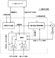
図1は、この発明の実施例を示す位置決め装置の回路構成図であり、この位置決め装置4は位置制御回路5とサーボモータ6とエンコーダ7とから形成されている。
FIG. 1 is a circuit configuration diagram of a positioning device showing an embodiment of the present invention. The
この位置制御回路5が図4に示した従来の位置制御回路3と異なる点は、位置決め完了処理部13が位置決め完了処理部15になっていることである。
The position control circuit 5 is different from the conventional position control circuit 3 shown in FIG. 4 in that the positioning
この演算部51,完了判別タイマ52,最小OFF時間タイマ53からなる位置決め完了処理部15では、位置・速度・電流制御部12からの位置情報としての位置偏差が所定値以下になったとき、エンコーダ7からの位置フィードバック信号の単位時間当たりの発生パルス数が所定値以下になったとき、位置指令生成部11からの位置指令が零またはほぼ零(≒0)になったときなどに、後述の図2,3に示す波形図のような動作をして、位置決め完了を上位コントローラ1へ発信するようにしている。
In the positioning
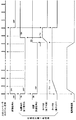
図2は、図1に示した位置制御回路5の位置決め完了処理部15の動作を説明する波形図であり、この図は前回の位置決め完了信号Bが発せられ、これを上位コントローラ1が認知した後に、外部から設定される位置設定値が「零」、すなわち、前回と同じ移動位置のままで、新たな起動信号Aが上位コントローラ1から発せられたときの位置決め完了処理部15の動作を説明する波形図である。
FIG. 2 is a waveform diagram for explaining the operation of the positioning
図2において、先ず、上位コントローラ1からのスキャン動作として、起動信号AがOFFからONに変化することにより、位置指令生成部11に起動信号Aが発せられると、位置指令生成部11を介した位置決め完了処理部15の演算部51では、この起動信号Aを受けて、位置決め完了信号BをONからOFFに変化させるとともに、位置到達信号CもONからOFFに変化させる。同時に、位置決め完了信号を出力する時限が外部から設定された最小OFF時間タイマ53を起動させる。
In FIG. 2, first, as a scanning operation from the
この最小OFF時間タイマ53は、上位コントローラ1のスキャン信号の1周期中に位置決め完了信号BがON→OFF→ONに変化すると、この変化を上位コントローラ1が検知できないので、上位コントローラ1が位置決め装置2での位置決め完了を確実に認知させるためのものであり、最小OFF時間タイマ53の設定時限Tmは上位コントローラ1の位置決め装置2に対するスキャン時間以上の長さに設定している。
When the positioning completion signal B changes from ON → OFF → ON during one cycle of the scan signal of the
その後、図示の僅かの時限Tkを経過しても、位置指令生成部11からの位置指令が零のままである、すなわち、エンコーダ7からの位置フィードバック信号としてのサーボモータ6が零速度であることから、位置決め完了処理部15の演算部51では前回と同じ移動位置のままで、再度、起動信号Aが上位コントローラ1から発せられたことを認知し、位置到達信号CをOFFからONに変化させる。
After that, even if the slight time limit Tk shown in the figure elapses, the position command from the position
このように、位置到達信号CがOFFからONに変化すると、演算部51では位置決め完了信号の継続を確認するための確認時限が外部から設定された完了判別タイマ52を起動させる。この完了判別タイマ52は、位置到達信号CのONが所定時間継続していることを確認するための確認時限を設定するためのものである。
As described above, when the position arrival signal C changes from OFF to ON, the
この完了判別タイマ52が図示の設定時限Tdを経過し、さらに、最小OFF時間タイマ53も図示の設定時限Tmを経過したことで、位置決め完了信号BをOFFからONに変化させ、この変化を直近のスキャン動作で上位コントローラ1が取り込み、今回の位置決め完了信号Bと認知するとともに、次のスキャン動作で起動信号AをONからOFFに変化させる。
The
このように、起動信号AがONからOFFに変化すると、位置指令生成部11を介した位置決め完了処理部15の演算部51では完了判別タイマ52と最小OFF時間タイマ53とをリセットして、一連の処理動作を終了し、次の起動信号Aを待つ状態に入る。
Thus, when the activation signal A changes from ON to OFF, the
すなわち、図2に示したこの発明の動作と図5に示した従来の動作とを比較すると、上位コントローラ1からのスキャン動作として、起動信号AがOFFからONに変化することにより起動信号Aが発せられるときから、従来の位置決め装置2では(時限Tk)+(設定時限Td)+(設定時限Tm)の時間が経過すると、位置決め完了信号Bが発せられるのに対して、この発明の位置決め装置4では、設定時限Tmが経過すると、位置決め完了信号Bが発せられる。その結果、この発明の位置決め装置4では、(時限Tk)+(設定時限Td)の時間だけ短く処理することができる。
That is, when the operation of the present invention shown in FIG. 2 and the conventional operation shown in FIG. 5 are compared, as the scan signal from the
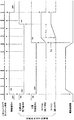
図3は、図1に示した位置制御回路5の位置決め完了処理部15の動作を説明する波形図であり、この図は前回の位置決め完了信号Bが発せられ、これを上位コントローラ1が認知した後に、外部から設定される位置設定値に基づき前回とは異なった移動位置での新たな起動信号Aが上位コントローラ1から発せられたときの位置決め完了処理部15の動作を説明する波形図である。
FIG. 3 is a waveform diagram for explaining the operation of the positioning
図3において、先ず、上位コントローラ1からのスキャン動作として、起動信号AがOFFからONに変化することにより起動信号Aが発せられると、位置決め完了処理部15ではこの起動信号Aを受けて、位置決め完了信号BをONからOFFに変化させるとともに、位置到達信号CもONからOFFに変化させる。同時に、最小OFF時間タイマ53を起動させる。
In FIG. 3, first, as a scanning operation from the
図3において、先ず、上位コントローラ1からのスキャン動作として、起動信号AがOFFからONに変化することにより起動信号Aが位置指令生成部11に発せられると、位置指令生成部11を介した位置決め完了処理部15の演算部51ではこの起動信号Aを受けて、位置決め完了信号BをONからOFFに変化させるとともに、位置到達信号CもONからOFFに変化させる。同時に、最小OFF時間の確認時限が外部から設定された最小OFF時間タイマ53を起動させる。
In FIG. 3, first, as a scanning operation from the
さらに、位置指令生成部11からの位置指令に基づいて、位置・速度・電流制御部12では、位置指令に対応した移動位置に到達するように、エンコーダ7からの位置フィードバック信号を監視しつつ、サーボモータ6を回転させる。
Further, based on the position command from the position
その後、位置決め完了処理部15の演算部51では、位置・速度・電流制御部12からの位置情報としての位置偏差が所定値以下になったとき、エンコーダ7からの位置フィードバック信号の単位時間当たりの発生パルス数が所定値以下になったとき、位置指令生成部11からの位置指令が零またはほぼ零(≒0)になったときなどを条件に、位置到達信号CをOFFからONに変化させる。
Thereafter, in the
このように、位置到達信号CがOFFからONに変化すると、演算部51では位置決め完了の完了判別時間の確認時限が外部から設定された完了判別タイマ52を起動させる。
As described above, when the position arrival signal C changes from OFF to ON, the
この完了判別タイマ52が図示の設定時限Tdを経過し、さらに、最小OFF時間タイマ53も図示の設定時限Tmを経過したことで、位置決め完了信号BをOFFからONに変化させ、この変化を直近のスキャン動作で上位コントローラ1が取り込み、今回の位置決め完了信号Bと認知するとともに、次のスキャン動作で起動信号AをONからOFFに変化させる。
The
このように、起動信号AがONからOFFに変化すると、位置指令生成部11を介した位置決め完了処理部15の演算部51では完了判別タイマ52と最小OFF時間タイマ53とをリセットして、一連の処理動作を終了し、次の起動信号Aを待つ状態に入る。
Thus, when the activation signal A changes from ON to OFF, the
すなわち、図3に示したこの発明の動作と図6に示した従来の動作とを比較すると、上位コントローラ1からのスキャン動作として、起動信号AがOFFからONに変化することにより起動信号Aが発せられ、位置到達信号CをOFFからONに変化したときから、従来の位置決め装置2では(設定時限Td)+(設定時限Tm)の時間が経過すると、位置決め完了信号Bが発せられるのに対して、この発明の位置決め装置4では、設定時限Tdが経過すると、位置決め完了信号Bが発せられる。その結果、この発明の位置決め装置4では、設定時限Tmの時間だけ短く処理することができる。
That is, when the operation of the present invention shown in FIG. 3 and the conventional operation shown in FIG. 6 are compared, as the scan operation from the
1…上位コントローラ、2…位置決め装置、3…位置制御回路、4…位置決め装置、5…位置制御回路、6…サーボモータ、7…エンコーダ、11…位置指令生成部、12…位置・速度・電流制御部、13…位置決め完了処理部、15…位置決め完了処理部。
DESCRIPTION OF
Claims (2)
前記位置制御回路は、
前記移動位置に到達したことを確認する時限を設定する完了判別タイマと、前記起動信号が発せられてから位置決め完了信号を出力する時限を設定する最小OFF時間タイマとを備え、
前記位置決め完了は、前記完了判別タイマの設定時限と最小OFF時間タイマの設定時限とが経過した時点で出力し、前記上位コントローラへ発信するようにしたことを特長とする位置決め装置。 When the position control circuit receives the start signal from the host controller, the position control circuit is configured to receive the servo motor until the set movement position is reached based on the position feedback signal from the encoder connected to the output shaft of the servo motor. In the positioning device that outputs a positioning completion signal when it is confirmed that the movement position has been reached,
The position control circuit includes:
A completion determination timer for setting a time period for confirming that the movement position has been reached, and a minimum OFF time timer for setting a time period for outputting a positioning completion signal after the start signal is issued,
The positioning device is characterized in that the positioning completion is output when the completion determination timer setting time limit and the minimum OFF time timer setting time limit have elapsed, and is transmitted to the host controller.
前記最小OFF時間タイマの設定時限は、前記上位コントローラの前記位置制御回路に対するスキャン時間以上の長さに設定したことを特長とする位置決め装置。 The positioning device according to claim 1,
The positioning apparatus according to claim 1, wherein the set time limit of the minimum OFF time timer is set to be longer than a scan time for the position control circuit of the host controller.
Priority Applications (1)
| Application Number | Priority Date | Filing Date | Title |
|---|---|---|---|
| JP2008233798A JP5396786B2 (en) | 2008-09-11 | 2008-09-11 | Positioning device |
Applications Claiming Priority (1)
| Application Number | Priority Date | Filing Date | Title |
|---|---|---|---|
| JP2008233798A JP5396786B2 (en) | 2008-09-11 | 2008-09-11 | Positioning device |
Publications (2)
| Publication Number | Publication Date |
|---|---|
| JP2010067077A true JP2010067077A (en) | 2010-03-25 |
| JP5396786B2 JP5396786B2 (en) | 2014-01-22 |
Family
ID=42192602
Family Applications (1)
| Application Number | Title | Priority Date | Filing Date |
|---|---|---|---|
| JP2008233798A Active JP5396786B2 (en) | 2008-09-11 | 2008-09-11 | Positioning device |
Country Status (1)
| Country | Link |
|---|---|
| JP (1) | JP5396786B2 (en) |
Cited By (2)
| Publication number | Priority date | Publication date | Assignee | Title |
|---|---|---|---|---|
| JP2011210245A (en) * | 2010-03-11 | 2011-10-20 | Panasonic Corp | Motor drive |
| JP2018171652A (en) * | 2017-03-30 | 2018-11-08 | リンカーン グローバル,インコーポレイテッド | Workpiece positioning device and welding sequencer |
Citations (5)
| Publication number | Priority date | Publication date | Assignee | Title |
|---|---|---|---|---|
| JPH0421385A (en) * | 1990-05-14 | 1992-01-24 | Toshiba Corp | Abnormality detector for servo motor controller |
| JPH06214656A (en) * | 1993-01-18 | 1994-08-05 | Fanuc Ltd | Sliding mode control method provided with damping element |
| JPH08161050A (en) * | 1994-12-05 | 1996-06-21 | Komatsu Ltd | Abnormality detecting method of movable body position detecting means |
| JPH11353027A (en) * | 1998-06-10 | 1999-12-24 | Sony Corp | Positioning controller |
| JP2003122432A (en) * | 2001-10-11 | 2003-04-25 | Yaskawa Electric Corp | Step-back operating method of program table operation |
-
2008
- 2008-09-11 JP JP2008233798A patent/JP5396786B2/en active Active
Patent Citations (5)
| Publication number | Priority date | Publication date | Assignee | Title |
|---|---|---|---|---|
| JPH0421385A (en) * | 1990-05-14 | 1992-01-24 | Toshiba Corp | Abnormality detector for servo motor controller |
| JPH06214656A (en) * | 1993-01-18 | 1994-08-05 | Fanuc Ltd | Sliding mode control method provided with damping element |
| JPH08161050A (en) * | 1994-12-05 | 1996-06-21 | Komatsu Ltd | Abnormality detecting method of movable body position detecting means |
| JPH11353027A (en) * | 1998-06-10 | 1999-12-24 | Sony Corp | Positioning controller |
| JP2003122432A (en) * | 2001-10-11 | 2003-04-25 | Yaskawa Electric Corp | Step-back operating method of program table operation |
Cited By (4)
| Publication number | Priority date | Publication date | Assignee | Title |
|---|---|---|---|---|
| JP2011210245A (en) * | 2010-03-11 | 2011-10-20 | Panasonic Corp | Motor drive |
| JP2018171652A (en) * | 2017-03-30 | 2018-11-08 | リンカーン グローバル,インコーポレイテッド | Workpiece positioning device and welding sequencer |
| JP7098379B2 (en) | 2017-03-30 | 2022-07-11 | リンカーン グローバル,インコーポレイテッド | Workpiece positioning device and welding sequencer |
| US11531318B2 (en) | 2017-03-30 | 2022-12-20 | Lincoln Global, Inc. | Workpiece positioner and welding sequencer |
Also Published As
| Publication number | Publication date |
|---|---|
| JP5396786B2 (en) | 2014-01-22 |
Similar Documents
| Publication | Publication Date | Title |
|---|---|---|
| JP2661422B2 (en) | Processing device and processing method | |
| JP2006236243A (en) | Motion control system and its synchronizing method | |
| JP6998512B2 (en) | Servo system and servo system control method | |
| CN108886481A (en) | Communication control system and communication control method | |
| JP5396786B2 (en) | Positioning device | |
| JP2018171667A (en) | Control device, control system, robot, and robot system | |
| JP2015159709A (en) | Motor controller and correction data creation method | |
| KR101340178B1 (en) | Motor driver control device | |
| US20130253668A1 (en) | Positioning apparatus and plc system using same | |
| JP2008090513A (en) | Numerical controller | |
| JP2011201009A (en) | Robot system | |
| JP2007025759A (en) | Electric motor driving device, position instruction device and positioning device | |
| US9836040B2 (en) | Motor control device, motor control system and motor control method | |
| WO2004001946A1 (en) | Motor control device | |
| JP2006285752A (en) | Synchronous control method and synchronous control device between two shaft | |
| JP4436809B2 (en) | Laser processing system | |
| JP2006285886A (en) | Control method of distributed motion control system | |
| JP2017205881A (en) | Motor-driven injection molding machine having driving shaft synchronously controlled by a plurality of servomotors | |
| JP2017204955A (en) | Pulse output logic circuit for motor control and controller unit for motor control | |
| JP2005246543A (en) | Robot system | |
| JP2021096604A (en) | Scanner controller and scanner control system | |
| JP6461440B1 (en) | Servo control device | |
| JP2020057088A (en) | Numerical control device | |
| JP2003088187A (en) | Motor controller | |
| JP5045066B2 (en) | Motor control system, synchronization method in motor control system, and control apparatus |
Legal Events
| Date | Code | Title | Description |
|---|---|---|---|
| A711 | Notification of change in applicant |
Free format text: JAPANESE INTERMEDIATE CODE: A712 Effective date: 20110422 |
|
| A621 | Written request for application examination |
Free format text: JAPANESE INTERMEDIATE CODE: A621 Effective date: 20110812 |
|
| A131 | Notification of reasons for refusal |
Free format text: JAPANESE INTERMEDIATE CODE: A131 Effective date: 20121023 |
|
| A521 | Request for written amendment filed |
Free format text: JAPANESE INTERMEDIATE CODE: A523 Effective date: 20121205 |
|
| A131 | Notification of reasons for refusal |
Free format text: JAPANESE INTERMEDIATE CODE: A131 Effective date: 20130402 |
|
| A521 | Request for written amendment filed |
Free format text: JAPANESE INTERMEDIATE CODE: A523 Effective date: 20130530 |
|
| TRDD | Decision of grant or rejection written | ||
| A01 | Written decision to grant a patent or to grant a registration (utility model) |
Free format text: JAPANESE INTERMEDIATE CODE: A01 Effective date: 20130924 |
|
| A61 | First payment of annual fees (during grant procedure) |
Free format text: JAPANESE INTERMEDIATE CODE: A61 Effective date: 20131007 |
|
| R150 | Certificate of patent or registration of utility model |
Free format text: JAPANESE INTERMEDIATE CODE: R150 Ref document number: 5396786 Country of ref document: JP Free format text: JAPANESE INTERMEDIATE CODE: R150 |
|
| R250 | Receipt of annual fees |
Free format text: JAPANESE INTERMEDIATE CODE: R250 |
|
| R250 | Receipt of annual fees |
Free format text: JAPANESE INTERMEDIATE CODE: R250 |
|
| R250 | Receipt of annual fees |
Free format text: JAPANESE INTERMEDIATE CODE: R250 |
|
| R250 | Receipt of annual fees |
Free format text: JAPANESE INTERMEDIATE CODE: R250 |
|
| R250 | Receipt of annual fees |
Free format text: JAPANESE INTERMEDIATE CODE: R250 |
|
| R250 | Receipt of annual fees |
Free format text: JAPANESE INTERMEDIATE CODE: R250 |
|
| R250 | Receipt of annual fees |
Free format text: JAPANESE INTERMEDIATE CODE: R250 |
|
| R250 | Receipt of annual fees |
Free format text: JAPANESE INTERMEDIATE CODE: R250 |