JP2010057730A - Received data processor for photoacoustic tomography - Google Patents
Received data processor for photoacoustic tomography Download PDFInfo
- Publication number
- JP2010057730A JP2010057730A JP2008227091A JP2008227091A JP2010057730A JP 2010057730 A JP2010057730 A JP 2010057730A JP 2008227091 A JP2008227091 A JP 2008227091A JP 2008227091 A JP2008227091 A JP 2008227091A JP 2010057730 A JP2010057730 A JP 2010057730A
- Authority
- JP
- Japan
- Prior art keywords
- acoustic wave
- photoacoustic tomography
- minimum
- data
- received
- Prior art date
- Legal status (The legal status is an assumption and is not a legal conclusion. Google has not performed a legal analysis and makes no representation as to the accuracy of the status listed.)
- Granted
Links
Images


Classifications
-
- A—HUMAN NECESSITIES
- A61—MEDICAL OR VETERINARY SCIENCE; HYGIENE
- A61B—DIAGNOSIS; SURGERY; IDENTIFICATION
- A61B5/00—Measuring for diagnostic purposes; Identification of persons
- A61B5/0093—Detecting, measuring or recording by applying one single type of energy and measuring its conversion into another type of energy
- A61B5/0095—Detecting, measuring or recording by applying one single type of energy and measuring its conversion into another type of energy by applying light and detecting acoustic waves, i.e. photoacoustic measurements
-
- A—HUMAN NECESSITIES
- A61—MEDICAL OR VETERINARY SCIENCE; HYGIENE
- A61B—DIAGNOSIS; SURGERY; IDENTIFICATION
- A61B5/00—Measuring for diagnostic purposes; Identification of persons
- A61B5/0059—Measuring for diagnostic purposes; Identification of persons using light, e.g. diagnosis by transillumination, diascopy, fluorescence
- A61B5/0073—Measuring for diagnostic purposes; Identification of persons using light, e.g. diagnosis by transillumination, diascopy, fluorescence by tomography, i.e. reconstruction of 3D images from 2D projections
-
- A—HUMAN NECESSITIES
- A61—MEDICAL OR VETERINARY SCIENCE; HYGIENE
- A61B—DIAGNOSIS; SURGERY; IDENTIFICATION
- A61B5/00—Measuring for diagnostic purposes; Identification of persons
- A61B5/72—Signal processing specially adapted for physiological signals or for diagnostic purposes
- A61B5/7225—Details of analog processing, e.g. isolation amplifier, gain or sensitivity adjustment, filtering, baseline or drift compensation
-
- A—HUMAN NECESSITIES
- A61—MEDICAL OR VETERINARY SCIENCE; HYGIENE
- A61B—DIAGNOSIS; SURGERY; IDENTIFICATION
- A61B5/00—Measuring for diagnostic purposes; Identification of persons
- A61B5/72—Signal processing specially adapted for physiological signals or for diagnostic purposes
- A61B5/7271—Specific aspects of physiological measurement analysis
- A61B5/7278—Artificial waveform generation or derivation, e.g. synthesising signals from measured signals
-
- A—HUMAN NECESSITIES
- A61—MEDICAL OR VETERINARY SCIENCE; HYGIENE
- A61B—DIAGNOSIS; SURGERY; IDENTIFICATION
- A61B8/00—Diagnosis using ultrasonic, sonic or infrasonic waves
- A61B8/13—Tomography
-
- A—HUMAN NECESSITIES
- A61—MEDICAL OR VETERINARY SCIENCE; HYGIENE
- A61B—DIAGNOSIS; SURGERY; IDENTIFICATION
- A61B8/00—Diagnosis using ultrasonic, sonic or infrasonic waves
- A61B8/48—Diagnostic techniques
- A61B8/483—Diagnostic techniques involving the acquisition of a 3D volume of data
Landscapes
- Health & Medical Sciences (AREA)
- Life Sciences & Earth Sciences (AREA)
- Engineering & Computer Science (AREA)
- Physics & Mathematics (AREA)
- Public Health (AREA)
- Surgery (AREA)
- Veterinary Medicine (AREA)
- General Health & Medical Sciences (AREA)
- Animal Behavior & Ethology (AREA)
- Biophysics (AREA)
- Pathology (AREA)
- Biomedical Technology (AREA)
- Heart & Thoracic Surgery (AREA)
- Medical Informatics (AREA)
- Molecular Biology (AREA)
- Nuclear Medicine, Radiotherapy & Molecular Imaging (AREA)
- Radiology & Medical Imaging (AREA)
- Signal Processing (AREA)
- Psychiatry (AREA)
- Computer Vision & Pattern Recognition (AREA)
- Physiology (AREA)
- Artificial Intelligence (AREA)
- Acoustics & Sound (AREA)
- Power Engineering (AREA)
- Ultra Sonic Daignosis Equipment (AREA)
- Investigating Or Analyzing Materials By The Use Of Ultrasonic Waves (AREA)
Abstract
Description
本発明は、光音響トモグラフィ診断装置等に用いられる光音響トモグラフィの受信データ処理装置に関し、特に音響波受信信号に基づいて画像データを生成する技術に関する。 The present invention relates to a photoacoustic tomography reception data processing apparatus used in a photoacoustic tomography diagnostic apparatus and the like, and more particularly to a technique for generating image data based on an acoustic wave reception signal.
従来より生体に電磁波を照射すると、生体の電磁波吸収に伴う生体組織の温度上昇・熱膨張により音響波が発生することが知られている。この現象を活用し、非侵襲で生体内を可視化しようとする光音響トモグラフィ(PAT:PhotoAcoustic Tomography)と呼ばれる技術が近年脚光を浴び、光音響トモグラフィ診断装置の臨床現場への適用が試られている。 Conventionally, when an electromagnetic wave is irradiated on a living body, it is known that an acoustic wave is generated due to a temperature rise and thermal expansion of a living tissue accompanying electromagnetic wave absorption of the living body. A technique called photoacoustic tomography (PAT) that attempts to visualize the inside of a living body by making use of this phenomenon has attracted attention in recent years, and application of a photoacoustic tomography diagnostic apparatus to a clinical site has been tried. ing.
光音響トモグラフィ診断装置では、ターゲットとする被検体に光を照射し、それに伴って発生する音響波を複数の微小振動素子を配列した1次元、または2次元の微小振動子アレイにより受信する。1次元、または2次元の微小振動子アレイとしては、通常超音波診断装置で用いられるプローブに類するものが使用されることが多い。 In the photoacoustic tomography diagnostic apparatus, light is irradiated onto a target subject, and an acoustic wave generated in response thereto is received by a one-dimensional or two-dimensional micro-vibrator array in which a plurality of micro-vibration elements are arranged. As the one-dimensional or two-dimensional micro-vibrator array, one similar to a probe usually used in an ultrasonic diagnostic apparatus is often used.
光音響トモグラフィにおける画像再構成においては、様々なアルゴリズムの適用が試られているが、一般に超音波診断装置の画像再構成に用いられる整相加算と呼ばれる手法の適用も可能である。 In image reconstruction in photoacoustic tomography, various algorithms have been applied, but a technique called phasing addition generally used for image reconstruction in an ultrasonic diagnostic apparatus can also be applied.
被検体への光照射後、音響波の受信時には、目標点から発生する音響波を受信することとなるが、目標点から各微小振動素子への距離は同一ではない。そのため、目標点から発生する音響波信号は各微小振動素子に異なる時間に到着する。そこで、一般的に光音響トモグラフィ診断装置においては、整相加算処理により異なる時間に到着する音響波信号の時間ずれを調整し、目標点に対応する光音響トモグラフィ画像データを生成する。生成された目標点のデータは、ピクセル、またはボクセルと呼ばれ、各々2次元、または3次元光音響トモグラフィ画像の最小構成単位となる。整相加算処理では、微小振動子アレイが受信した音響波アナログ信号をアンプにより増幅し、ADコンバータにてアナログ―デジタル変換を行った後、音響波受信デジタル信号を記憶装置に保持する。そして、同一目標点に由来する信号値を必要なすべてのチャンネルにおいて加算するものである。 When an acoustic wave is received after light irradiation to the subject, an acoustic wave generated from the target point is received, but the distance from the target point to each micro-vibration element is not the same. Therefore, the acoustic wave signal generated from the target point arrives at each micro vibrating element at different times. Therefore, in general, in a photoacoustic tomography diagnostic apparatus, time lag of acoustic wave signals that arrive at different times is adjusted by phasing addition processing, and photoacoustic tomography image data corresponding to a target point is generated. The generated target point data is called a pixel or a voxel and is a minimum unit of a two-dimensional or three-dimensional photoacoustic tomography image. In the phasing addition processing, the acoustic wave analog signal received by the micro-vibrator array is amplified by an amplifier, and after analog-digital conversion by an AD converter, the acoustic wave reception digital signal is held in a storage device. Then, signal values derived from the same target point are added in all necessary channels.
また、光音響トモグラフィ診断装置においては、1次元、または2次元の微小振動子アレイの指向性改善のため、アポダイゼーション(apodization)と呼ばれる処理が行われる。これは、微小振動子アレイ中の各微小振動素子で受信した音響波信号を均等に加算するのではなく、ある微小振動素子アレイ領域に到達する音響波信号を減衰させる。それにより、目的方向以外に由来する音響波信号の勢力を抑え、微小振動素子アレイの指向性を改善する処理である。一般的には、各微小信号素子で受信した各音響波信号に対し、異なる重み付け係数を掛け、窓関数あるいは立体角と距離に依存した関数を掛けたのと同様の効果を得ようとしている。 In the photoacoustic tomography diagnostic apparatus, a process called apodization is performed to improve the directivity of a one-dimensional or two-dimensional micro-vibrator array. This does not add evenly the acoustic wave signals received by each micro-vibration element in the micro-vibrator array, but attenuates the acoustic wave signal reaching a certain micro-vibration element array region. Thereby, the force of the acoustic wave signal originating from the direction other than the target direction is suppressed, and the directivity of the micro vibrating element array is improved. In general, each acoustic wave signal received by each minute signal element is multiplied by a different weighting coefficient to obtain the same effect as a window function or a function depending on a solid angle and a distance.
デジタル信号の整相加算処理では、各受信チャンネル毎に遅延時間調整のための遅延装置を用いている。遅延装置としては、主にFIFO(先入れ先出し)メモリやRAM(Random Access Memory)などの記憶装置が用いられている。 In the phasing addition processing of the digital signal, a delay device for adjusting the delay time is used for each reception channel. As the delay device, a storage device such as a FIFO (first-in first-out) memory or a RAM (Random Access Memory) is mainly used.
近年はFPGA(Field Programmable Gate Array)チップが大規模化している。さらに、高速読み出し・書き込み可能なFIFO(先入れ先出し)メモリやRAM(Random Access Memory)メモリを搭載してい
る。よって、光音響トモグラフィの受信データ処理装置をFPGAチップに実装しやすい状況となっている。しかし、FPGAチップに搭載されているロジック、高速メモリの容量にも限りがある。また大規模なFPGAチップは高価であり、可能な限り少ないロジック、メモリ容量で構成可能な光音響トモグラフィの受信データ処理装置が求められている。
In recent years, FPGA (Field Programmable Gate Array) chips have been enlarged. Further, a FIFO (first-in first-out) memory and a RAM (Random Access Memory) memory capable of high-speed reading / writing are mounted. Therefore, it is easy to mount the received data processing device of photoacoustic tomography on the FPGA chip. However, the capacity of logic and high-speed memory mounted on the FPGA chip is limited. A large-scale FPGA chip is expensive, and a photoacoustic tomography reception data processing apparatus that can be configured with as little logic and memory capacity as possible is demanded.
下記特許文献1,2には、光を被検体に照射し、その結果被検体が熱膨張・収縮を起こすことにより発生する音響波を受信して得られる電気信号から画像を構成する技術が開示されている。
しかし、これらの特許文献1,2に開示されている先行例においては、多数の受信チャンネルを具備した光音響トモグラフィ診断装置を構成しようとすると、装置が複雑化・大規模化しやすいという問題がある。すなわち、受信回路の規模が大きくなり、コストの増大につながっていた。また、光音響トモグラフィの画像再構成をソフトウェアを用いて行った場合、光音響トモグラフィ画像取得に時間がかかる。
However, in the prior examples disclosed in these
本発明は、上述の問題に鑑みてなされたものである。超音波診断装置の分野においても同様の課題があり、様々な対処がなされているが、光音響トモグラフィ診断装置のイメージングの特質には、超音波診断装置におけるイメージングの特質とは異なる点がある。そのため、その特質を活用した別の有効な対処法が存在する。 The present invention has been made in view of the above problems. There are similar problems in the field of ultrasonic diagnostic equipment, and various countermeasures have been taken, but the imaging characteristics of the photoacoustic tomography diagnostic apparatus are different from the imaging characteristics of the ultrasonic diagnostic apparatus. . For this reason, there is another effective countermeasure that takes advantage of this characteristic.
光音響トモグラフィ診断装置と超音波診断装置におけるイメージング特質の違いの第一点目は、光照射、超音波発信の間隔時間である。光音響トモグラフィの場合、実用的な光エネルギー(数mJ以上)を発生させる光源の制約上、光の照射間隔はある一定時間(数十ms)以上に設定する必要がある。つまり、光照射後に長い待機時間を取る必要がある。一方超音波診断装置においてはそのような制約はない。それどころか、観察深さ分の信号の受信が完了し次第、即座に超音波送信を行い、フレームレートを向上させる必要がある。超音波送信間隔時間は、長くても数百μs程度である。 The first difference in the imaging characteristics between the photoacoustic tomography diagnostic apparatus and the ultrasonic diagnostic apparatus is the interval time between light irradiation and ultrasonic transmission. In the case of photoacoustic tomography, the light irradiation interval needs to be set to a certain fixed time (several tens of milliseconds) due to restrictions of a light source that generates practical light energy (several mJ or more). That is, it is necessary to take a long standby time after light irradiation. On the other hand, there is no such restriction in the ultrasonic diagnostic apparatus. On the contrary, as soon as the reception of the signal for the observation depth is completed, it is necessary to immediately transmit the ultrasonic wave and improve the frame rate. The ultrasonic transmission interval time is about several hundreds μs at the longest.
光音響トモグラフィ診断装置と超音波診断装置におけるイメージング特質の違いの第二点目は、観察深さとそれにともなう受信時間の違いである。光音響トモグラフィ診断装置においては、人体における光の減衰が激しいため、観察深さは数cmに限られる。一方、超音波診断装置では、観察深さを数十cmに設定することも可能である。よって、光音響トモグラフィでは、光照射後、受信データ取り込み時間は数十μs程度で済む。また、超音波診断装置では、数十cmの深さを観察する場合、受信データ取り込み時間は数百μs程度になる。例えば、20cmの深さを観察する場合、受信データ取り込み時間は260μs程度になる。 The second difference in the imaging characteristics between the photoacoustic tomography diagnostic apparatus and the ultrasonic diagnostic apparatus is the difference in observation depth and reception time associated therewith. In the photoacoustic tomography diagnostic apparatus, since the attenuation of light in the human body is severe, the observation depth is limited to a few cm. On the other hand, in the ultrasonic diagnostic apparatus, the observation depth can be set to several tens of centimeters. Therefore, in photoacoustic tomography, the reception data capture time after light irradiation is only about several tens of μs. Further, in the ultrasonic diagnostic apparatus, when observing a depth of several tens of centimeters, the reception data capturing time is about several hundred μs. For example, when observing a depth of 20 cm, the reception data capturing time is about 260 μs.
このように、超音波診断装置においては、受信データ取り込み時間が終了するとすぐに送信が行われるため、リアルタイム性を保つには、受信しながら整相加算を行い、画像データ生成する必要がある。この場合、受信チャンネルに入ってくるデータを同時に処理する必要があるため、受信チャンネル数が大きくなると装置規模も大きくなり、装置の高コスト化へとつながる。 As described above, in the ultrasonic diagnostic apparatus, transmission is performed as soon as the reception data capturing time ends. Therefore, in order to maintain real-time characteristics, it is necessary to perform phasing addition while receiving and generate image data. In this case, since it is necessary to simultaneously process data entering the reception channel, the device scale increases as the number of reception channels increases, leading to higher device costs.
一方、光音響トモグラフィ診断装置においては、光照射間隔が長く、受信データ取り込み時間が短い。つまり長い待機時間が存在する。よって、一旦、受信データを記憶媒体に
取り込んでおきさえすれば、画像データ生成はその後十分に時間をかけて行うことができる。これは、受信データ処理回路規模を小さくし、画像データ生成を時分割で行えることを意味する。そもそも、光音響トモグラフィ画像のリアルタイム性は光照射時間で律速されるものであるため、待機時間内に画像データ生成できさえすれば、画像のリアルタイム性に悪影響はない。
On the other hand, in the photoacoustic tomography diagnostic apparatus, the light irradiation interval is long and the reception data capturing time is short. That is, there is a long waiting time. Therefore, once the received data is taken into the storage medium, the image data can be generated after a sufficient amount of time. This means that the received data processing circuit scale can be reduced and image data can be generated in a time-sharing manner. In the first place, since the real-time property of the photoacoustic tomography image is limited by the light irradiation time, the real-time property of the image is not adversely affected as long as image data can be generated within the standby time.
本発明は、以上のような光音響トモグラフィの特質を活用し、小規模な構成で、高速に光音響トモグラフィの画像再構成を行いうる、新規な構造の光音響トモグラフィの受信データ処理装置を提供することを目的としている。 The present invention utilizes the characteristics of photoacoustic tomography as described above, and processes received data of photoacoustic tomography with a novel structure that can perform photoacoustic tomography image reconstruction at high speed with a small-scale configuration. The object is to provide a device.
上記目的を達成するために、本発明は、光を被検体に照射し、その結果被検体が局部的に熱膨張・収縮を起こすことにより発生する音響波を受信して得られる電気信号から画像を構成する光音響トモグラフィの受信データ処理装置において、処理対象とする被検体領域由来の音響波を受信する複数の音響波受信素子からの受信信号をデジタル化する複数の電気信号変換手段と、電気信号変換手段によってデジタル化された受信デジタル信号を記憶する複数の第一の記憶手段と、被検体領域を分割した各最小構成単位から音響波が各音響波受信素子に到達するとした場合の音響波の遅延情報に従い、前記複数の第一の記憶手段より各最小構成単位由来の受信デジタル信号を順次読み出し、整相加算することにより各最小構成単位毎の音響波のデータである最小構成単位データの合成を行う最小構成単位データ合成手段と、被検体領域全体の最小構成単位データを保存可能な第二の記憶手段と、第二の記憶手段に保存された最小構成単位データに基づき被検体領域の画像を構成する画像構成手段と、最小構成単位データ合成手段によって合成された各最小構成単位データを順次第二の記憶手段に記憶し、記憶された被検体領域全体の最小構成単位データを読み出して画像構成手段に送る制御手段と、を具備してなることを特徴とする。 In order to achieve the above object, the present invention provides an image from an electrical signal obtained by irradiating a subject with light and, as a result, receiving an acoustic wave generated by the subject locally causing thermal expansion and contraction. A plurality of electrical signal conversion means for digitizing received signals from a plurality of acoustic wave receiving elements for receiving acoustic waves derived from a subject region to be processed; A plurality of first storage means for storing the received digital signals digitized by the electrical signal conversion means, and an acoustic wave when the acoustic wave reaches each acoustic wave receiving element from each minimum structural unit obtained by dividing the subject region In accordance with the wave delay information, the received digital signals derived from each minimum structural unit are sequentially read out from the plurality of first storage means and phased and added to demodulate the acoustic wave for each minimum structural unit. A minimum configuration unit data synthesizing unit that synthesizes the minimum configuration unit data, a second storage unit capable of storing the minimum configuration unit data of the entire subject area, and a minimum configuration stored in the second storage unit An image composing means for constructing an image of the subject area based on the unit data, and each minimum constituent unit data synthesized by the minimum constituent unit data synthesizing means are sequentially stored in the second storage means, and the entire stored subject area Control means for reading out the minimum structural unit data and sending it to the image construction means.
本発明によれば、小規模な構成で、高速に光音響トモグラフィの2次元または3次元の画像再構成を行うことができる。 According to the present invention, two-dimensional or three-dimensional image reconstruction of photoacoustic tomography can be performed at high speed with a small configuration.
以下、本発明を実施するための形態について、図面を参照しながら詳しく説明する。 Hereinafter, embodiments for carrying out the present invention will be described in detail with reference to the drawings.
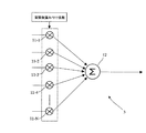
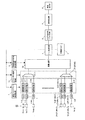
図1は、本発明の実施例1に係る光音響トモグラフィの受信データ処理装置を示す図である。図1では、光音響トモグラフィの受信データ処理装置の総チャンネル数がNの場合の例を示している。 FIG. 1 is a diagram illustrating a received data processing apparatus for photoacoustic tomography according to a first embodiment of the present invention. FIG. 1 shows an example in which the total number of channels of the received data processing device for photoacoustic tomography is N.
この光音響トモグラフィの受信データ処理装置は、光を被検体に照射し、その結果被検体が局部的に熱膨張・収縮を起こすことにより発生する音響波を受信して得られる電気信号から画像を構成するものである。
装置構成は、N個のADコンバータ1−1〜1−Nと、N個の遅延記憶メモリ(遅延記憶M)2−1〜2−Nと、演算回路3、とを具備する。加えて、メモリ制御回路4、再構成メモリ5、窓関数重み係数計算回路6、遅延メモリアドレス計算回路7、信号処理ブロック8、画像構成部9、画像表示部10、とを具備している。
This photoacoustic tomography reception data processing apparatus irradiates a subject with light and, as a result, receives an acoustic wave generated by locally subjecting the subject to thermal expansion and contraction, and receives an image from an electrical signal obtained. It constitutes.
The apparatus configuration includes N AD converters 1-1 to 1-N, N delay storage memories (delay storage M) 2-1 to 2-N, and an
ADコンバータ1−1〜1−Nは電気信号変換手段であり、音響波受信アレイ52の音響波受信素子54−1〜54−Nによって受信されたアナログの電気信号をデジタル化す
るものである。音響波受信アレイ52は受信手段を構成するもので、処理対象とする被検体領域由来の音響波をN個の音響波受信素子54−1〜54−Nによって受信してアナログ
の電気信号に変換する。
遅延記憶メモリ2−1〜2−Nは第一の記憶手段であり、ADコンバータ1−1〜1−Nによってデジタル化された受信デジタル信号を時系列に記憶する。
The AD converters 1-1 to 1-N are electric signal conversion means, and digitize analog electric signals received by the acoustic wave receiving elements 54-1 to 54-N of the acoustic
The delay storage memories 2-1 to 2-N are first storage means, and store the received digital signals digitized by the AD converters 1-1 to 1-N in time series.
演算回路3は最小構成単位データ合成手段であり、複数の遅延記憶メモリ2−1〜2−Nより、ターゲットとする被検体領域を分割した最小構成単位である各ボクセル由来の受
信デジタル信号を順次読み出し、ボクセルデータを合成する。このボクセルデータが最小構成単位毎の音響波のデータである。各ボクセル由来の受信デジタル信号の読み出しは、各ボクセルから音響波が各音響波受信素子54−1〜54−Nに到達するとした場合の音
響波の遅延情報に従ってなされ、読み出された受信デジタル信号を整相加算する。
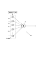
演算回路3は、図2に示すように、N個の乗算器11−1〜11−Nと、一つの加算回路12と、を有している。
The
As shown in FIG. 2, the
再構成メモリ5は第二の記憶手段であり、被検体領域全体のボクセルデータを保存可能となっている。
画像構成部9は画像構成手段であり、再構成メモリ5に保存されたボクセルデータに基づき被検体領域の画像を構成する。
The
The
また、メモリ制御回路4が制御手段であり、演算回路3によって演算された各ボクセルデータを順次第二の記憶手段である再構成メモリ5に記憶し、記憶された被検体領域全体のボクセルデータを読み出して画像構成部9に送る。
遅延メモリアドレス計算回路7はアドレス演算手段であり、被検体領域の各最小構成単位座標であるボクセル座標より、各ボクセルから各音響波受信素子54−1〜54−Nに
到達する音響波の遅延時間を算出する。そして、各遅延メモリ2−1〜2−Nに対して、
遅延時間に対応する各ボクセル由来の受信デジタル信号が格納されているアドレスを供給する。
Further, the
The delay memory
An address in which a received digital signal derived from each voxel corresponding to the delay time is stored is supplied.
窓関数重み係数計算回路6は窓関数重み係数演算手段であり、ターゲットとする被検体領域のボクセル座標より、音響波の受信信号が伝送される受信チャンネル毎の窓関数重み係数を算出し、算出した窓関数重み係数を演算回路3に与える。
信号処理ブロック8は信号処理手段であり、ローパスフィルタ、ハイパスフィルタ等のフィルタ処理、対数圧縮(log圧縮)処理、微分処理、包絡線検波処理、直交検波処理といった信号処理がなされる。
The window function weighting coefficient calculation circuit 6 is a window function weighting coefficient calculating means, and calculates a window function weighting coefficient for each reception channel through which an acoustic wave reception signal is transmitted, from the voxel coordinates of the target subject area. The obtained window function weighting coefficient is given to the
The
次に、本実施例1の動作について、具体的に説明する。
図示しない光源からレーザ光等の光が被検体に照射され、その結果、被検体が居部的に熱膨張・収縮を起こすことにより音響波が発生する。この音響波が音響波受信素子アレイ52のN個の受信素子54−1〜54−Nによって受信され、アナログ電気信号に変換される。このアナログ電気信号が、N個のADコンバータ1−1〜1−Nによりデジタル化され、N個の遅延記憶メモリ(遅延記憶M)2−1〜2−Nへ出力される。
遅延記憶メモリ(遅延記憶M)2−1〜2−Nは、ADコンバータ1−1〜1−Nより出力されたデジタル信号を記憶する。
Next, the operation of the first embodiment will be specifically described.
The subject is irradiated with light such as laser light from a light source (not shown), and as a result, the subject undergoes thermal expansion / contraction locally, thereby generating an acoustic wave. This acoustic wave is received by the N receiving elements 54-1 to 54-N of the acoustic wave receiving
The delay memory (delay memory M) 2-1 to 2-N stores the digital signals output from the AD converters 1-1 to 1-N.
遅延メモリアドレス計算回路7は、ターゲットとする被検体領域内のボクセル座標に基づき、ターゲットボクセルに対応する遅延時間と遅延記憶メモリアドレスを計算し、遅延記憶メモリアドレスを遅延記憶メモリ2−1〜2−Nに供給する。被検体領域内の最小構成単位由来、すなわちターゲットボクセル由来の受信デジタルデータは、遅延メモリアドレス計算回路7が算出した遅延記憶メモリアドレスに従って、遅延記憶メモリ2−1〜2−Nより読み出される。そして、演算回路3の乗算器11−1〜11−Nに出力される。
The delay memory
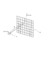
図3は、ターゲットとする被検体領域内のターゲットボクセル53と、音響波受信素子アレイ52、アレイ中の音響波受信素子54との位置関係の一例を示している。ターゲットボクセル53と、アレイ中の音響波受信素子54間の距離Dは、ある一定の座標系の下、ターゲットボクセル53の座標(X1,Y1,Z1)とアレイ中の音響波受信素子54の座標(X2,Y2,Z2)を決定すると、三平方の定理により即座に求まる。
FIG. 3 shows an example of the positional relationship between the
また、ターゲットボクセル53と、アレイ中の音響波受信素子54間の距離Dを音速で除算することにより、ターゲットボクセル53からアレイ中の音響波受信素子54までの、音響波到達時間(遅延時間)が算出される。
Also, by dividing the distance D between the
加えて、ターゲットとする被検体領域内から音響波を受信している間、遅延記憶メモリ2−1〜2−Nは、遅延記憶メモリ2−1〜2−N中の各アドレスに音響波由来のデジタルデータを順次時系列で、しかもある一定の規則に従って記憶する。すなわち、各遅延記憶メモリ2−1〜2−Nには、光が照射された時点から受信デジタル信号が時系列に読み込まれ、音響波が発生したボクセル位置からの距離に応じた遅延時間毎に到達した音響波の信号が記憶されることになる。 In addition, while the acoustic wave is being received from the target subject area, the delay storage memories 2-1 to 2-N are derived from the acoustic wave at each address in the delay storage memories 2-1 to 2-N. Are sequentially stored in time series according to certain rules. That is, in each delay storage memory 2-1 to 2 -N, the received digital signal is read in time series from the time when the light is irradiated, and for each delay time corresponding to the distance from the voxel position where the acoustic wave is generated. The reached acoustic wave signal is stored.
このターゲットボクセル53からアレイ中の音響波受信素子54−1〜54−Nまでの
音響波到達時間(遅延時間)と、遅延記憶メモリ2−1〜2−Nにおけるデジタルデータ
記憶の規則を基に遅延記憶メモリアドレスを特定できる。この遅延メモリアドレスは、あるターゲットボクセル由来のデジタルデータが存在するメモリアドレスである。
Based on the acoustic wave arrival time (delay time) from the
本発明では、遅延メモリアドレス計算回路7が、ターゲットボクセル毎に、遅延記憶メモリアドレスの算出を行い、算出された遅延記憶メモリアドレスを遅延記憶メモリ2−1〜2−Nに供給する。そして、遅延記憶メモリ2−1〜2−Nは、遅延メモリアドレス計算回路7より与えられた遅延記憶メモリアドレスに従い、最小構成単位由来、すなわちターゲットボクセル由来のデジタルデータを演算回路3に出力する。
In the present invention, the delay memory
窓関数重み係数計算回路6は、ターゲットとする被検体領域内のボクセル座標に基き、ターゲットボクセルに対応する窓関数重み係数を計算し、演算回路3に供給する。遅延記憶メモリ2−1〜2−Nから出力された受信デジタル信号は、アポダイゼーションのため、チャンネル毎に、窓関数重み係数計算回路6が算出した窓関数重み係数を付され、加算回路12へ出力される。
The window function weighting coefficient calculation circuit 6 calculates a window function weighting coefficient corresponding to the target voxel based on the voxel coordinates in the target subject area, and supplies the window function weighting coefficient to the
加算回路12は、窓関数重み係数を付されたすべてのチャンネルの受信デジタル信号を加算する。このような処理によって、ターゲットボクセル由来の音響波受信シグナル情報である受信デジタル信号が整相加算される。
The
整相加算されたターゲットボクセルデータは、メモリ制御回路4を介して再構成メモリ5に記憶される。この処理を、全てのボクセルに対して繰り返し行うことで、ターゲットとする被検体領域内全てのボクセルデータを順次整相加算し、再構成メモリ5に保存する。
The phased and added target voxel data is stored in the
一旦、ターゲットとする被検体領域内全てのボクセルデータが整相加算され再構成メモリ5に保存されると、メモリ制御回路4がボクセルデータを信号処理ブロック8に出力する。信号処理ブロック8は、入力されたボクセルデータに、対数圧縮処理・フィルタ処理等の信号処理を施した後、画像構成部9に出力する。信号処理は、ローパスフィルタ、ハイパスフィルタ等のフィルタ処理、対数圧縮処理、微分処理、包絡線検波処理、直交検波処理といった処理を含む。また、信号処理に必要なパラメータを算出し、信号処理ブロック8に与えるようにしてもよい(図示せず)。
画像構成部9は、信号処理を施されたボクセルデータに基づき、光音響トモグラフィ画像の構成を行い、画像表示部10に出力する。画像表示部10では、構成された光音響トモグラフィ画像を表示する。これが、実施例1の一連の動作である。
Once all the voxel data in the target subject region are phased and added and stored in the
The
光音響トモグラフィの場合、実用的な光エネルギー(数mJ以上)を発生させる光源の制約上、光の照射間隔はある一定時間以上に設定する必要がある。本実施例では、光の照射間隔、いわゆる待ち時間を活用して光音響トモグラフィの受信データの成形を行う。よって、次の光照射開始前にターゲットとする被検体領域内全てのボクセルデータ生成を終了させれば、本実施例に示された動作により、光音響トモグラフィ画像のリアルタイム性を損うことはない。 In the case of photoacoustic tomography, it is necessary to set the light irradiation interval to a certain fixed time or more due to restrictions on a light source that generates practical light energy (several mJ or more). In the present embodiment, reception data of photoacoustic tomography is formed by utilizing a light irradiation interval, so-called waiting time. Therefore, if the generation of all voxel data in the target object region is terminated before the start of the next light irradiation, the real-time property of the photoacoustic tomography image is impaired by the operation shown in this embodiment. Absent.
光音響トモグラフィにおいては、光を被検体に照射して得られる音響波のS/Nが低い場合、複数回の受信シグナルの加算平均処理を行い、S/Nを向上させる必要が出てくる。その場合、複数回の受信において得られる最小構成単位データであるターゲットボクセルの整相加算データをメモリ制御回路4と再構成メモリ5を用いて加算平均してもよい。この場合、メモリ制御回路4が加算平均手段となる。
このような構成を取ると、すべての処理が終わった時点で加算平均され、S/Nが向上したターゲットボクセルデータが再構成メモリ5に保存されることとなる。
In photoacoustic tomography, when the S / N of an acoustic wave obtained by irradiating a subject with light is low, it is necessary to perform an averaging process of a plurality of received signals to improve the S / N. . In that case, the phasing addition data of the target voxel, which is the minimum unit data obtained in a plurality of receptions, may be averaged using the
When such a configuration is adopted, the target voxel data with the S / N improved is stored in the
上記遅延記憶メモリ2−1〜2−N、再構成メモリ5に使用するメモリの種類については、特に限定するものでない。FIFO(先入れ先出しメモリ)を用いて構成してもよく、またはRAM(ランダムアクセスメモリ)を用いて構成してもよい(図示せず)。適用可能であれば、他の記憶手段を用いてもよい。
The types of memories used for the delay storage memories 2-1 to 2-N and the
また、信号処理ブロック8は、必ずしも図1に示すように画像構成部9の直前に配置される必要はない。必要に応じ、光音響トモグラフィの受信データ処理装置中のどの位置に配置してもよく、また、必ずしも1つである必要もない。例えば、演算回路3中に配置してもよいし、音響波受信素子の受信チャンネル毎に配置してもよいし、受信チャンネル毎に遅延記憶メモリ2−1〜2−Nの出力部に1つずつ配置してもよい(図示せず)。その場合、信号処理に必要なパラメータをチャンネル毎に独立して算出し、与えるようにしてもよい(図示せず)。
Further, the
また、演算回路3は、必ずしも図2に示すように、乗算と加算処理だけを行う必要はない。必要に応じ、その他、光音響トモグラフィ画像再構成に必要な演算、信号処理手段を加えてもよい(図示せず)。信号処理に必要なパラメータをチャンネル毎に独立して算出し、与えるようにしてもよい(図示せず)。その場合、演算回路3の中にパラメータ演算手段を配置しても良いし、別途演算ブロックを用意し、算出パラメータを演算回路3に供給するようにしてもよい(図示せず)。
The
また、光音響トモグラフィの受信データ処理装置の実装手段は、必ずしもFPGAに限定する必要はない。必要に応じ、DSP(Digital Signal Processor)や汎用CPU、各種揮発性メモリ、不揮発性メモリ等を組み合わせて装置を構成してもよい(図示せず)。 Also, the means for mounting the received data processing device of photoacoustic tomography is not necessarily limited to the FPGA. If necessary, the apparatus may be configured by combining a DSP (Digital Signal Processor), a general-purpose CPU, various volatile memories, nonvolatile memories, and the like (not shown).
また、音響波受信素子アレイ52は、必ずしも図3に示すように、2Dアレイである必要はない。例えば、1D、1.5Dアレイを用いてもよい(図示せず)。また、通常の超音波診断装置においては、探触子形状として、リニア、セクタ、コンベックス等複数の形態が存在するが、本発明においても、音響波受信に使用する探触子形状を限定する必要はない(図示せず)。
Further, the acoustic wave receiving
また、画像構成部9の実現法についても、特に限定するものではない。汎用CPU(Central Processing Unit)やGPU (Graphic Processing Unit)等を用いてもよく、適宜他の手段を用いてもよい(図示せず)。
Further, the implementation method of the
次に、本発明の他の実施例について説明する。以下の説明では、主として上記実施例1及び先行する実施例と異なる部分についてのみ説明するものとし、同一の構成部分については、同一の符号を付して説明を省略するものとする。 Next, another embodiment of the present invention will be described. In the following description, only parts different from those of the first embodiment and the preceding embodiments will be mainly described, and the same components will be denoted by the same reference numerals and description thereof will be omitted.
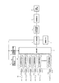
図4は、本発明の実施例2に係る光音響トモグラフィの受信データ処理装置を示す図である。図4では、音響波受信素子数がLで、光音響トモグラフィの受信データ処理装置の総チャンネル数がNの場合の例を示している。このとき、L>N、つまり音響波受信素子数が、光音響トモグラフィの受信データ処理装置の総チャンネル数よりも多い場合を示している。 FIG. 4 is a diagram illustrating a received data processing apparatus for photoacoustic tomography according to the second embodiment of the present invention. FIG. 4 shows an example in which the number of acoustic wave receiving elements is L and the total number of channels of the received data processing device for photoacoustic tomography is N. In this case, L> N, that is, the number of acoustic wave receiving elements is greater than the total number of channels of the photoacoustic tomography reception data processing device.
この光音響トモグラフィの受信データ処理装置は、N個のADコンバータ1−1〜1−N、N個の遅延記憶メモリ(遅延記憶M)2−1〜2−N、演算回路3と、を具備する。加えて、メモリ制御回路4、再構成メモリ5、窓関数重み係数計算回路6、遅延メモリアドレス計算回路7、対数圧縮、フィルタ処理を行う信号処理ブロック8、画像構成部9、画像表示部10と、を具備する。加えて、音響波受信素子54−1〜54−LとADコンバータ1−1〜1−Nの間に、接続状態を切り替える接続切り替え手段としてのスイッチング回路16が配置される。
This photoacoustic tomography reception data processing apparatus includes N AD converters 1-1 to 1-N, N delay storage memories (delay storage M) 2-1 to 2-N, and an
以下に、この実施例2の動作について説明する。
N個のADコンバータ1−1〜1−N以降の各回路の動作は、基本的に実施例1と同じである。しかし、スイッチング回路16により、音響波受信素子54−1〜54−LとADコンバータ1−1〜1−Nとの接続状態を切り替えることができる点が実施例1と異なっている。
The operation of the second embodiment will be described below.
The operation of each circuit after the N AD converters 1-1 to 1-N is basically the same as that of the first embodiment. However, it is different from the first embodiment in that the switching
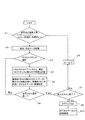
図5は、実施例2の動作のフローチャートである。
まず、L個ある音響波受信素子54−1〜54−Lの中からN個(a,a+1,a+2….a+N−1)を選び、光音響トモグラフィの受信データ処理装置のN個のチャンネルに接続する(S1参照)。
FIG. 5 is a flowchart of the operation of the second embodiment.
First, N (a, a + 1, a + 2... A + N-1) are selected from the L acoustic wave receiving elements 54-1 to 54-L, and N channels of the received data processing device for photoacoustic tomography are selected. (See S1).
次に、被検体のターゲット領域に光を照射し、それにより発生した音響波を受信し、ADコンバータ1−1〜1−Nによってデジタル化する。デジタル化された受信データは、N個の遅延記憶メモリ2−1〜2−Nに記憶される(S2参照)。 Next, the target region of the subject is irradiated with light, and the acoustic wave generated thereby is received and digitized by the AD converters 1-1 to 1-N. The digitized reception data is stored in N delay storage memories 2-1 to 2-N (see S2).
次に、整相加算を行うターゲットボクセルを決定し、整相加算に必要な遅延メモリアドレスと重み付け係数を計算する。そして、計算された遅延メモリアドレスと重み付け係数に基いて整相加算を行い再構成メモリ5に格納する(S5参照)。 Next, a target voxel for performing phasing addition is determined, and a delay memory address and a weighting coefficient necessary for phasing addition are calculated. Then, phasing addition is performed based on the calculated delay memory address and weighting coefficient, and the result is stored in the reconfiguration memory 5 (see S5).
一旦、選択したターゲットボクセルの整相加算が終了すると、全ボクセルの選択が完了したかどうかを判定し、完了していない場合はS3に戻り、次のターゲットボクセルを選択し、整相加算を行い再構成メモリ5に格納する。この処理を、ターゲット領域のすべてのボクセルについて整相加算が終了するまで繰り返す。この時点で、最初に選択した音響波受信素子グループ(a,a+1,a+2….a+N−1)で受信した音響波に基づくターゲットボクセルの整相加算が終了する。
Once the phasing addition of the selected target voxels is completed, it is determined whether or not all voxels have been selected. If not, the process returns to S3 to select the next target voxel and perform phasing addition. Store in the
次に、選択するN個の音響波受信素子を変更する。
図5では、L個の音響波受信素子のうち、音響波受信素子(a+1,a+2….a+N)を新たに選択している例を示している(S8、S1参照)。次に、被検体のターゲット領域に光を照射し、それにより発生した音響波を、新たに選択したN個の音響波受信素子(a+1,a+2….a+N)を用いて受信する。そして、ターゲット領域のすべてのボクセルについて整相加算を行い、時分割にて順次得られる最小構成単位データとしてのボクセルデータを、再構成メモリ5中の同一ボクセルデータに累積加算する(S2〜S5参照)。
Next, N acoustic wave receiving elements to be selected are changed.
FIG. 5 shows an example in which acoustic wave receiving elements (a + 1, a + 2... A + N) are newly selected from the L acoustic wave receiving elements (see S8 and S1). Next, the target region of the subject is irradiated with light, and the acoustic waves generated thereby are received using N newly selected acoustic wave receiving elements (a + 1, a + 2... A + N). Then, phasing addition is performed on all the voxels in the target area, and voxel data as minimum constituent unit data sequentially obtained by time division is cumulatively added to the same voxel data in the reconfiguration memory 5 (see S2 to S5). ).
このような処理を、受信を行いたい全ての音響波受信素子54−1〜54−Lが選択され、全てのターゲットボクセルの整相加算が終了するまで繰り返す(S7)。全ての音響波受信素子54−1〜54−Lについて受信スキャンが終了したら、受信走査は終了し(S9参照)、再構成メモリ5に記憶されているボクセルデータを読み出して画像構成に移る(S10)。
Such processing is repeated until all the acoustic wave receiving elements 54-1 to 54-L to be received are selected and the phasing addition of all target voxels is completed (S7). When the reception scan is completed for all the acoustic wave receiving elements 54-1 to 54-L, the reception scan is completed (see S9), the voxel data stored in the
以上のような手順を用いることで、音響波受信素子54−1〜54−Lアレイにおける受信領域を変更・分割して受信を行うことが可能となる。この手法の利点は、音響波受信素子アレイ52における音響波受信素子数Lより少ない光音響トモグラフィの受信データ処理装置のチャンネル数で、光音響トモグラフィ画像の再構成が可能となる。
By using the procedure as described above, it is possible to perform reception by changing / dividing the reception area in the acoustic wave receiving elements 54-1 to 54-L array. The advantage of this technique is that the photoacoustic tomography image can be reconstructed with the number of photoacoustic tomography reception data processing devices smaller than the number L of acoustic wave receiving elements in the acoustic wave receiving
また、同一のターゲットボクセルのデータを、音響波受信素子54−1〜54−Lにおける異なる受信領域にて受信する場合もありえる。この場合、メモリ制御回路4と再構成メモリ5にて、同一のターゲットボクセルデータを累積加算、または加算平均処理し、ターゲットボクセルデータを生成する。音響波受信素子54−1〜54−Lアレイにおける受信領域が異なる場合、演算回路3中の乗算器11−1〜11−Nにて受信データに付する重み付け係数が変更されることもあり得る。
In addition, the data of the same target voxel may be received in different reception areas in the acoustic wave receiving elements 54-1 to 54-L. In this case, the same target voxel data is cumulatively added or averaged in the
本実施例のように、ターゲットボクセルデータを処理・保存しておくためのメモリ制御回路4と再構成メモリ5を設けたことで、全ての音響波受信素子に対し、光音響トモグラフィの受信データ処理装置を同時に接続する必要がなくなる。つまり、光音響トモグラフィの受信データ処理装置を小型化できる。
As in this embodiment, by providing the
ここで、音響波受信素子54−1〜54−Lにおける受信領域選択方式は、図5に示したものと必ず同一である必要はなく、適宜必要に応じて選択方式は決定すればよい。加えて、音響波受信素子数L、全ての光音響トモグラフィの受信データ処理装置のチャンネル数Nとの関係は、必ずしもL>Nに限定されない。更に、受信中に、全ての光音響トモグラフィの受信データ処理装置のチャンネルが使用されなければならないということもない。 Here, the reception area selection method in the acoustic wave receiving elements 54-1 to 54-L is not necessarily the same as that shown in FIG. 5, and the selection method may be determined as necessary. In addition, the relationship between the number of acoustic wave receiving elements L and the number of channels N of all photoacoustic tomography reception data processing devices is not necessarily limited to L> N. Furthermore, during reception, the channels of all photoacoustic tomography received data processing devices must not be used.
なお、ADコンバータ1と遅延記憶メモリ2の間に接続状態を切り替える接続切り替え手段としてのスイッチング回路を設け、ADコンバータ1と遅延記憶メモリ2の接続状態を順次変更しながら音響波受信を行ってもよい(図示せず)。たとえば、ADコンバータ1の総数がL、遅延記憶メモリ2の総数がNのとき(L>N)、ADコンバータ1と遅延記憶メモリ2の接続状態を受信毎に順次変更する。そして、受信を行いたい全てのADコンバータ1が選択され、全てのターゲットボクセルの整相加算が終了するまで処理を続行する。
Note that a switching circuit as a connection switching means for switching the connection state between the
このように、ADコンバータ1と遅延記憶メモリ2の間の接続状態、音響波受信素子アレイ52とADコンバータ1間の接続状態を順次変更しながら音響波受信を行う構成を取ることも可能である。
In this way, it is possible to adopt a configuration in which acoustic wave reception is performed while sequentially changing the connection state between the
光音響トモグラフィの場合、光源の制約上、光の照射間隔はある一定時間以上に設定する必要がある。本実施例では、光の照射間隔、いわゆる待ち時間を活用して光音響トモグラフィ受信データ成形を行う。よって、次の光照射開始前にターゲットとする被検体領域内全てのボクセルデータ生成を終了させれば、本実施例に示された動作により、光音響トモグラフィ画像のリアルタイム性を損うことはない。 In the case of photoacoustic tomography, it is necessary to set the light irradiation interval to a certain fixed time or more due to restrictions on the light source. In this embodiment, photoacoustic tomography reception data shaping is performed by utilizing a light irradiation interval, so-called waiting time. Therefore, if the generation of all voxel data in the target object region is terminated before the start of the next light irradiation, the real-time property of the photoacoustic tomography image is impaired by the operation shown in this embodiment. Absent.
スイッチング回路16を音響波受信素子アレイ52とADコンバータ1間に設けることで、音響波受信素子よりも少ないADコンバータ数で装置構成できる。加えて、ADコンバータ1と遅延記憶メモリ2間にスイッチング回路を設けることにより、ADコンバータよりも少ない遅延記憶メモリ数で装置構成できる。
By providing the switching
また、対数圧縮、フィルタ処理等を行う信号処理ブロック8は、必ずしも図4に示すように画像構成部9の直前に配置される必要はない。必要に応じ、演算回路3に設けてもよいし、スイッチング回路16から演算回路3を結ぶN個のチャンネル毎に配置してもよい。また、必ずしも1つである必要もない。例えば、演算回路3中に配置してもよいし、各チャンネル毎に遅延記憶メモリ2−1〜2−Nの出力部に1つずつ配置してもよい(図示せず)。その場合、信号処理に必要なパラメータをチャンネル毎に算出し、与えるようにしてもよい(図示せず)。
Further, the
図6は、本発明の実施例3に係る光音響トモグラフィの受信データ処理装置を示す図である。図6では、光音響トモグラフィの受信データ処理装置の総チャンネル数がNの場合の例を示している。 FIG. 6 is a diagram illustrating a received data processing apparatus for photoacoustic tomography according to a third embodiment of the present invention. FIG. 6 shows an example in which the total number of channels of the received data processing device for photoacoustic tomography is N.
この光音響トモグラフィの受信データ処理装置は、N個のADコンバータ1−1〜1−N、加算平均回路15−1〜15−N、N個の遅延記憶メモリ(遅延記憶M)2−1〜2
−N、演算回路3、とを具備する。加えて、メモリ制御回路4、再構成メモリ5、窓関数重み係数計算回路6、遅延メモリアドレス計算回路7、信号処理ブロック8、画像構成部9、画像表示部10、とを具備する。
この実施例3では、加算平均手段としての加算平均回路15−1〜15−Nを有する点で実施例1、2と相違している。
This photoacoustic tomography reception data processing apparatus includes N AD converters 1-1 to 1-N, addition averaging circuits 15-1 to 15-N, and N delay storage memories (delay storage M) 2-1. ~ 2
-N and the
The third embodiment is different from the first and second embodiments in that it includes addition averaging circuits 15-1 to 15-N as addition averaging means.
以下に、実施例3の動作について説明する。
N個のADコンバータ1−1〜1−Nの動作、演算回路3以降の各回路の動作は基本的に実施例1、実施例2と同じである。しかし、遅延記憶メモリ2−1〜2−Nが加算平均回路15−1〜15−Nと協働し、受信デジタル信号の加算平均処理が可能である点が実施例1、2と異なっている。
Hereinafter, the operation of the third embodiment will be described.
The operations of the N AD converters 1-1 to 1-N and the operations of the circuits after the
光音響トモグラフィにおいては、光を被検体に照射して得られる音響波のS/Nが低い場合、受信シグナルの加算平均処理を行う必要が出てくる。本実施例3では、加算平均回路15−1〜15−Nと遅延記憶メモリ2−1〜2−Nを協働させ、遅延記憶メモリ2−1〜2−Nに加算平均処理された受信データを蓄積する。その上で、ターゲットボクセルデータの整相加算処理を行うようになっている。本実施例3によれば、S/Nを向上させたターゲットボクセルデータを得ることが可能となる。 In photoacoustic tomography, when the S / N of an acoustic wave obtained by irradiating a subject with light is low, it is necessary to perform an averaging process of received signals. In the third embodiment, the addition averaging circuits 15-1 to 15-N and the delay storage memories 2-1 to 2-N cooperate to receive data that has been subjected to addition averaging processing in the delay storage memories 2-1 to 2-N. Accumulate. In addition, the phasing addition processing of the target voxel data is performed. According to the third embodiment, target voxel data with improved S / N can be obtained.
光音響トモグラフィの場合、光源の制約上、光の照射間隔はある一定時間以上に設定する必要がある。本実施例では、光の照射間隔、いわゆる待ち時間を活用して光音響トモグラフィ受信データ成形を行う。よって、加算平均を行うための複数回の光照射後、次の光照射開始前にターゲットとする被検体領域内全てのボクセルデータ生成を終了させさえす
れば、光音響トモグラフィ画像のリアルタイム性を損うことはない。
In the case of photoacoustic tomography, it is necessary to set the light irradiation interval to a certain fixed time or more due to restrictions on the light source. In this embodiment, photoacoustic tomography reception data shaping is performed by utilizing a light irradiation interval, so-called waiting time. Therefore, the real-time property of the photoacoustic tomography image can be improved as long as the generation of all voxel data in the target object region is completed after the light irradiation is performed a plurality of times to perform the averaging, before the start of the next light irradiation. There is no loss.
なお、この実施例3において、ADコンバータ1と加算平均回路の間にスイッチング回路を設け、ADコンバータ1と加算平均回路の接続状態を順次変更しながら音響波受信を行ってもよい(図示せず)。たとえば、ADコンバータの総数がL、加算平均回路の総数がNのとき(L>N)、ADコンバータと加算平均回路の接続状態を受信毎に順次変更する。そして、受信を行いたい全てのADコンバータが選択され、全てのターゲットボクセルの整相加算が終了するまで処理を続行する。このように、加算平均回路とADコンバータ間に切り替え制御手段としてのスイッチング回路を設けることで、ADコンバータ数よりも少ない加算平均回路・遅延記憶メモリ数で装置構成できる。
In the third embodiment, a switching circuit may be provided between the
さらに、この構成に加え、実施例2において、図4に示したように、音響波受信素子アレイとADコンバータ間のスイッチング回路を追加してもよい(図示せず)。音響波受信素子アレイとADコンバータ間にスイッチング回路を設けることにより、音響波受信素子アレイよりも少ないADコンバータ数で装置構成できる。。 Further, in addition to this configuration, in the second embodiment, as shown in FIG. 4, a switching circuit between the acoustic wave receiving element array and the AD converter may be added (not shown). By providing a switching circuit between the acoustic wave receiving element array and the AD converter, the apparatus can be configured with a smaller number of AD converters than the acoustic wave receiving element array. .
このように、ADコンバータと加算平均回路・遅延記憶メモリの間の接続状態、音響波受信素子アレイとADコンバータ間の接続状態を順次変更しながら音響波受信を行う構成を取ってもよい。 As described above, the acoustic wave reception may be performed while sequentially changing the connection state between the AD converter and the averaging circuit / delay storage memory and the connection state between the acoustic wave receiving element array and the AD converter.
図7は、本発明の実施例4に係る光音響トモグラフィの受信データ処理装置を示す図である。図7では、光音響トモグラフィの受信データ処理装置の総チャンネル数がNの例を示している。 FIG. 7 is a diagram illustrating a received data processing apparatus for photoacoustic tomography according to a fourth embodiment of the present invention. FIG. 7 shows an example in which the total number of channels of the received data processing device for photoacoustic tomography is N.
この光音響トモグラフィの受信データ処理装置は、N個のADコンバータ1−1〜1−N、N個の遅延記憶メモリ(遅延記憶M)2−1〜2−N、及び演算回路28を具備している。加えて、メモリ制御回路4、再構成メモリ5、窓関数重み係数計算回路6、遅延メモリアドレス計算回路7、信号処理ブロック8、画像構成部9、画像表示部10、とを具備している。
この実施例4では、遅延記憶メモリ2−1〜2−Nと演算回路3の間にメモリ選択スイッチ27−1〜27−(N/M)が配置されている。そして、M個の遅延記憶メモリがグループ化されて、メモリ選択スイッチ27−1〜27−(N/M)に接続され、メモリ選択スイッチ27−1〜27−(N/M)がチャンネル選択回路32によって選択される構成となっている。
This photoacoustic tomography reception data processing apparatus includes N AD converters 1-1 to 1-N, N delay storage memories (delay storage M) 2-1 to 2-N, and an
In the fourth embodiment, memory selection switches 27-1 to 27-(N / M) are arranged between the delay storage memories 2-1 to 2 -N and the
図8は、演算回路28の構成を示す図である。この演算回路28は、(N/M)個の乗算器50−1〜50−(N/M)と加算回路51と、を具備する。メモリ選択スイッチ27−1〜27−(N/M)の出力は、乗算器50−1〜50−(N/M)へ接続される。
FIG. 8 is a diagram showing the configuration of the
次に、実施例4の動作について説明する。
N個のADコンバータ1−1〜1−Nの動作は基本的に他の実施例と同じである。しかし、メモリ選択スイッチ27−1〜27−(N/M)により、遅延記憶メモリ2−1〜2−Nと演算回路3との接続状態を順次切り替えることができる点が、実施例1乃至3と異なっている。
Next, the operation of the fourth embodiment will be described.
The operations of the N AD converters 1-1 to 1-N are basically the same as those of the other embodiments. However, the first to third embodiments are that the connection state between the delay storage memories 2-1 to 2-N and the
図9は、実施例4の動作フローチャートである。
まず、被検体のターゲット領域に光を照射し、それにより発生した音響波を受信し、ADコンバータ1−1〜1−Nによってデジタル化する。デジタル化された受信データは、N個の遅延記憶メモリ2−1〜2−Nに記憶される(S41参照)。次に、N個ある遅延
記憶メモリ2−1〜2−Nの中から(N/M)個(a,a+M,a+2M….a+N−M)を選び、演算回路3の乗算器に接続する(S42参照)。
FIG. 9 is an operation flowchart of the fourth embodiment.
First, the target region of the subject is irradiated with light, and the acoustic waves generated thereby are received and digitized by the AD converters 1-1 to 1-N. The digitized reception data is stored in N delay storage memories 2-1 to 2-N (see S41). Next, (N / M) (a, a + M, a + 2M... A + N−M) are selected from the N delay storage memories 2-1 to 2-N and connected to the multiplier of the arithmetic circuit 3 ( (See S42).
その上で、整相加算を行うターゲットボクセルを決定し(S43参照)、整相加算に必要な遅延メモリアドレスと重み付け係数を計算する(S44参照)。そして、計算された遅延メモリアドレスと重み付け係数に基いて整相加算を行い再構成メモリ5に記憶する(S45参照)。一旦、選択したターゲットボクセルの整相加算が終了すると、次のターゲットボクセルを選択し、整相加算を行う(S46、S43参照)。この処理をターゲット領域のすべてのボクセルについて整相加算が終了するまで繰り返す。この時点で、遅延記憶メモリ2−1〜2−Nの中から最初に選択した(N/M)個(a,a+M,a+2M….a+N−M)の遅延記憶メモリ中に記憶したデジタルデータに基いたターゲット領域のすべてのボクセルの整相加算が終了する(S46参照)。 After that, a target voxel for performing phasing addition is determined (see S43), and a delay memory address and a weighting coefficient necessary for phasing addition are calculated (see S44). Then, phasing addition is performed based on the calculated delay memory address and the weighting coefficient, and the result is stored in the reconfiguration memory 5 (see S45). Once the phasing addition of the selected target voxel is completed, the next target voxel is selected and the phasing addition is performed (see S46 and S43). This process is repeated until the phasing addition is completed for all voxels in the target area. At this time, the digital data stored in the (N / M) (a, a + M, a + 2M... A + N−M) first selected from the delay storage memories 2-1 to 2-N The phasing addition of all the voxels in the target area is completed (see S46).
次に、新たに(N/M)個の遅延記憶メモリを選択する(S47、S48参照)。 図9では、N個の遅延記憶メモリ26−1〜26−Nのうち、遅延記憶メモリ(a+1,a+M+1,a+2M+1…,a+N−M+1)を新たに選択している例を示している。遅延記憶メモリを選択した後、ターゲット領域のすべてのボクセルについて整相加算を行う(S43〜S46参照)。 Next, (N / M) new delay storage memories are selected (see S47 and S48). FIG. 9 shows an example in which delay storage memories (a + 1, a + M + 1, a + 2M + 1..., A + N−M + 1) are newly selected from the N delay storage memories 26-1 to 26-N. After selecting the delay storage memory, phasing addition is performed for all voxels in the target area (see S43 to S46).
このような処理を、全ての遅延記憶メモリ2−1〜2−Nが選択されるまで繰り返す(S47参照)。全ての遅延機構メモリ群についての読み取りが終了したら、読み取りは終了し(S49参照)、再構成メモリ5に記憶されているボクセルデータを読み出して画像構成に移る(S50)。
Such processing is repeated until all the delay storage memories 2-1 to 2-N are selected (see S47). When reading for all the delay mechanism memory groups is completed, the reading ends (see S49), the voxel data stored in the
また、この場合、同一のターゲットボクセルのデータを、異なる遅延記憶メモリ2−1〜2−Nから読み出すこととなるが、メモリ制御回路4と再構成メモリ5にて、同一のターゲットボクセルデータを累積加算、または加算平均処理する。
こうして、ターゲット領域のすべてのボクセルデータが生成される。
In this case, the same target voxel data is read from different delay storage memories 2-1 to 2 -N, but the same target voxel data is accumulated in the
In this way, all the voxel data of the target area are generated.
このように、メモリ選択スイッチ27−1〜27−(N/M)を遅延記憶メモリ2−1〜2−Nと演算回路28間に設けることで、演算回路28規模を小さくできる。
Thus, by providing the memory selection switches 27-1 to 27-(N / M) between the delay storage memories 2-1 to 2-N and the
図9に示した手順では、一回の受信で得た受信データを遅延記憶メモリ2−1〜2−Nを複数グループに分け、順次選択しながら整相加算している。そのため、例えば実施例1に比べるとターゲット領域のすべてのボクセルデータ生成に時間がかかる。光音響トモグラフィの場合、光源の制約上、光の照射間隔はある一定時間以上に設定する必要がある。よって、本実施利のような整相加算の時分割処理を行っても、次の光照射までにターゲット領域のすべてのボクセルデータ生成が終了させることが可能である。つまり、本実施例4においても、フレームレートに対する悪影響は生じず、光音響トモグラフィ画像のリアルタイム性を損うことはない。 In the procedure shown in FIG. 9, the received data obtained by one reception is divided into a plurality of groups in the delay storage memories 2-1 to 2-N, and phased and added while being sequentially selected. Therefore, for example, it takes time to generate all the voxel data in the target area as compared with the first embodiment. In the case of photoacoustic tomography, it is necessary to set the light irradiation interval to a certain fixed time or more due to restrictions on the light source. Therefore, even if the time-sharing process of phasing addition as in the present embodiment is performed, it is possible to finish generating all the voxel data in the target area before the next light irradiation. That is, also in the fourth embodiment, there is no adverse effect on the frame rate, and the real-time property of the photoacoustic tomography image is not impaired.
本実施例4においても、ターゲットボクセルデータを処理・保存しておくためのメモリ制御回路4、再構成メモリ5を設けたことで、全ての遅延記憶メモリ2−1〜2−N中のデータを同時に演算回路28で処理する必要がなくなる。よって、小規模な光音響トモグラフィの受信データ処理装置による、ターゲット領域内の全ボクセルデータの時分割生成が可能となる。
ここで、遅延記憶メモリ2−1〜2−Nの選択方式は、図7に示したものと必ず同一である必要はなく、適宜必要に応じて選択方式は決定すればよい。
Also in the fourth embodiment, by providing the
Here, the selection method of the delay storage memories 2-1 to 2-N is not necessarily the same as that shown in FIG. 7, and the selection method may be determined as necessary.
また、この構成に加え、ADコンバータと遅延記憶メモリの間にスイッチング回路を設
け、ADコンバータと遅延記憶メモリの接続状態を順次変更しながら音響波受信を行ってもよい(図示せず)。たとえば、ADコンバータの総数がL、遅延記憶メモリの総数がNのとき(L>N)、ADコンバータと遅延記憶メモリの接続状態を受信毎に順次変更する。そして、受信を行いたい全てのADコンバータが選択され、全てのターゲットボクセルの整相加算が終了するまで処理を続行する。ADコンバータと遅延記憶メモリ間にスイッチング回路を設けることにより、ADコンバータよりも少ない遅延記憶メモリ数で装置構成できる。
In addition to this configuration, a switching circuit may be provided between the AD converter and the delay storage memory, and acoustic waves may be received while sequentially changing the connection state between the AD converter and the delay storage memory (not shown). For example, when the total number of AD converters is L and the total number of delay storage memories is N (L> N), the connection state between the AD converter and the delay storage memory is sequentially changed for each reception. Then, all AD converters to be received are selected, and the process is continued until the phasing addition of all target voxels is completed. By providing a switching circuit between the AD converter and the delay storage memory, the apparatus can be configured with a smaller number of delay storage memories than the AD converter.
さらに、この構成に加え、実施例2において、図4に示したように、音響波受信素子アレイとADコンバータ間のスイッチング回路を追加してもよい(図示せず)。このように、音響波受信素子アレイとADコンバータ間にスイッチング回路を設けることで、音響波受信素子よりも少ないADコンバータ数で装置構成できる。 Further, in addition to this configuration, in the second embodiment, as shown in FIG. 4, a switching circuit between the acoustic wave receiving element array and the AD converter may be added (not shown). Thus, by providing the switching circuit between the acoustic wave receiving element array and the AD converter, the apparatus can be configured with a smaller number of AD converters than the acoustic wave receiving elements.
こうして、演算回路28と遅延記憶メモリ間の接続状態、ADコンバータと遅延記憶メモリの間の接続状態、音響波受信素子アレイとADコンバータ間の接続状態を順次変更しながら音響波受信を行う構成を取ることも可能である。
In this way, a configuration for performing acoustic wave reception while sequentially changing the connection state between the
また、演算回路28は、必ずしも図8に示すように、乗算と加算処理だけを行う必要はない。必要に応じ、その他光音響トモグラフィ画像再構成に必要な演算、信号処理手段を加えてもよい(図示せず)。その場合、信号処理に必要な独立したパラメータをチャンネル毎に算出し、与えるようにしてもよい。
Further, the
図10は、本発明の実施例5に係る光音響トモグラフィの受信データ処理装置を示す図である。図10では、光音響トモグラフィの受信データ処理装置の総チャンネル数がNの例を示している。 FIG. 10 is a diagram illustrating a received data processing apparatus for photoacoustic tomography according to a fifth embodiment of the present invention. FIG. 10 shows an example in which the total number of channels of the received data processing apparatus for photoacoustic tomography is N.
この音響波受信データ成形装置も、N個のADコンバータ1−1〜1−N、N個の遅延記憶メモリ(遅延記憶M)2−1〜2−N、及び演算回路28を有している。加えて、メモリ制御回路4、再構成メモリ5、窓関数重み係数計算回路6、遅延メモリアドレス計算回路7、信号処理ブロック8、画像構成部9、画像表示部10と、を具備している。
This acoustic wave reception data shaping apparatus also includes N AD converters 1-1 to 1-N, N delay storage memories (delay storage M) 2-1 to 2-N, and an
また、実施例4と同様に、遅延記憶メモリ2−1〜2−Nと演算回路28の間にメモリ選択スイッチ27−1〜27−(N/M)が配置されている。そして、M個の遅延記憶メモリがグループ化されて、メモリ選択スイッチ27−1〜27−(N/M)に接続され、メモリ選択スイッチ27−1〜27−(N/M)がチャンネル選択回路32によって選択される構成となっている。
さらに、この実施例5では、実施例3と同様に、ADコンバータ1−1〜1−Nと遅延記憶メモリ(遅延記憶M)2−1〜2−Nの間に、加算平均手段としての加算平均回路38−1〜38−Nを有している。この点が実施例4と相違する。
Similarly to the fourth embodiment, memory selection switches 27-1 to 27-(N / M) are arranged between the delay storage memories 2-1 to 2 -N and the
Further, in the fifth embodiment, as in the third embodiment, addition as an averaging means is performed between the AD converters 1-1 to 1-N and the delay memory (delay memory M) 2-1 to 2-N. Average circuits 38-1 to 38-N are provided. This point is different from the fourth embodiment.
次に、実施例5の動作について説明する。
ADコンバータ1−1〜1−Nの動作は基本的に実施例4と同様である。しかし、遅延記憶メモリ2−1〜2−Nが加算平均回路38−1〜38−Nと協働し、受信データの加算平均処理が可能である点が実施例4と異なっている。
Next, the operation of the fifth embodiment will be described.
The operations of the AD converters 1-1 to 1-N are basically the same as those in the fourth embodiment. However, this embodiment is different from the fourth embodiment in that the delay storage memories 2-1 to 2-N cooperate with the addition averaging circuits 38-1 to 38-N and can perform addition averaging processing of received data.
光音響トモグラフィにおいては、光を被検体に照射して得られる音響波のS/Nが低い場合、受信シグナルの加算平均処理を行う必要が出てくる。本実施例4では、加算平均回路38−1〜38−Nと遅延記憶メモリ2−1〜2−Nを協働させ、遅延記憶メモリ2−1〜2−Nに加算平均処理された受信データを蓄積した上で、ターゲットボクセルデータ
の整相加算処理を行っている。本実施例によれば、S/Nを向上させたターゲットボクセルデータを得ることが可能となる。
In photoacoustic tomography, when the S / N of an acoustic wave obtained by irradiating a subject with light is low, it is necessary to perform an averaging process of received signals. In the fourth embodiment, the averaging data 38-1 to 38-N and the delay storage memories 2-1 to 2-N cooperate to receive data that has been subjected to addition averaging processing in the delay storage memories 2-1 to 2-N. Is accumulated, and the phasing addition processing of the target voxel data is performed. According to the present embodiment, it is possible to obtain target voxel data with improved S / N.
光音響トモグラフィの場合、光源の制約上、光の照射間隔はある一定時間以上に設定する必要がある。本実施例では、光の照射間隔、いわゆる待ち時間を活用して光音響トモグラフィ受信データ成形を行う。よって、加算平均を行うための複数回の光照射後、次の光照射開始前にターゲットとする被検体領域内全てのボクセルデータ生成を終了させさえすれば、光音響トモグラフィ画像のリアルタイム性を損うことはない。 In the case of photoacoustic tomography, it is necessary to set the light irradiation interval to a certain fixed time or more due to restrictions on the light source. In this embodiment, photoacoustic tomography reception data shaping is performed by utilizing a light irradiation interval, so-called waiting time. Therefore, the real-time property of the photoacoustic tomography image can be improved as long as the generation of all voxel data in the target object region is completed after the light irradiation is performed a plurality of times to perform the averaging, before the start of the next light irradiation. There is no loss.
本実施例においては、ターゲットボクセルデータを処理・保存しておくためのメモリ制御回路4、再構成メモリ5を設けたことで、全ての遅延記憶メモリ2−1〜2−N中のデータを同時に演算回路28で処理する必要がなくなる。よって、小規模な光音響トモグラフィの受信データ処理装置による、ターゲット領域内の全ボクセルデータの時分割生成が可能となる。
In this embodiment, by providing the
ここで、遅延記憶メモリ2−1〜2−Nの選択方式は、図10に示したものと必ず同一である必要はなく、適宜必要に応じて選択方式は決定すればよい。 Here, the selection method of the delay storage memories 2-1 to 2-N is not necessarily the same as that shown in FIG. 10, and the selection method may be determined as appropriate.
また、この構成に加え、ADコンバータと加算平均回路の間にスイッチング回路を設け、ADコンバータと加算平均回路の接続状態を順次変更しながら音響波受信を行ってもよい(図示せず)。たとえば、ADコンバータの総数がL、加算平均回路の総数がNのとき(L>N)、ADコンバータと加算平均回路の接続状態を受信毎に順次変更する。そして、受信を行いたい全てのADコンバータが選択され、全てのターゲットボクセルの整相加算が終了するまで処理を続行する。ADコンバータと加算平均回路間にスイッチング回路を設けることにより、ADコンバータよりも少ない加算平均回路・遅延記憶メモリ数で装置構成できる。 In addition to this configuration, a switching circuit may be provided between the AD converter and the averaging circuit, and acoustic waves may be received while sequentially changing the connection state between the AD converter and the averaging circuit (not shown). For example, when the total number of AD converters is L and the total number of addition average circuits is N (L> N), the connection state between the AD converter and the addition average circuit is sequentially changed for each reception. Then, all AD converters to be received are selected, and the process is continued until the phasing addition of all target voxels is completed. By providing a switching circuit between the AD converter and the averaging circuit, the apparatus can be configured with a smaller number of averaging circuits and delay storage memories than the AD converter.
さらに、この構成に加え、実施例2において、図4に示したように、音響波受信素子アレイとADコンバータ間のスイッチング回路を追加してもよい(図示せず)。このように、音響波受信素子アレイとADコンバータ間にスイッチング回路を設けることで、音響波受信素子よりも少ないADコンバータ数で装置構成できる。 Further, in addition to this configuration, in the second embodiment, as shown in FIG. 4, a switching circuit between the acoustic wave receiving element array and the AD converter may be added (not shown). Thus, by providing the switching circuit between the acoustic wave receiving element array and the AD converter, the apparatus can be configured with a smaller number of AD converters than the acoustic wave receiving elements.
こうして、演算回路28と遅延記憶メモリ2−1〜2−N間の接続状態、ADコンバータと加算平均回路の間の接続状態、音響波受信素子アレイとADコンバータ間の接続状態を順次変更しながら音響波受信を行う構成を取ることも可能である。
Thus, the connection state between the
なお、全ての実施例において、ADコンバータより後段の構成の動作周波数を変化させることにより、ボクセルデータ合成の処理速度を変化可能とした回路の動作周波数を向上させることができる。また、回路を複数並列に配置することで、ボクセルデータ生成速度を向上させることが可能であることは言うまでもない。 In all of the embodiments, the operating frequency of the circuit that can change the processing speed of the voxel data synthesis can be improved by changing the operating frequency of the configuration subsequent to the AD converter. It goes without saying that the voxel data generation speed can be improved by arranging a plurality of circuits in parallel.
また、各実施例の説明は、3次元画像の再構成を念頭においたものとなっているが、最小構成単位をピクセルデータとして2次元画像の再構成も可能であることは言うまでもない。 In the description of each embodiment, the reconstruction of a three-dimensional image is taken into consideration, but it is needless to say that the reconstruction of a two-dimensional image can be performed using the minimum structural unit as pixel data.
以上、本発明の好適な実施形態を説明したが、上述した実施形態は、あらゆる点で単なる例示にすぎず、本発明の範囲を限定するものではなく、本発明の趣旨を逸脱しない範囲で種々の変形が可能である。 The preferred embodiments of the present invention have been described above. However, the above-described embodiments are merely examples in all respects, and do not limit the scope of the present invention, and various modifications can be made without departing from the spirit of the present invention. Can be modified.
1−1〜1−N:ADコンバータ(電気信号変換手段)
2−1〜2−N:遅延調整メモリ(第一の記憶手段)
3:演算回路(最小構成単位データ合成手段)
4:メモリ制御回路(制御手段)
5:再構成メモリ(第二の記憶手段)
6:窓関数重み係数計算回路(窓関数重み係数演算手段)
7:遅延メモリアドレス計算回路(遅延メモリアドレス演算手段)
8:信号処理ブロック(信号処理手段)
9:画像構成部(画像構成手段)
10:画像表示部
11:乗算器
12:加算回路
15−1〜15−N:加算平均回路
16:スイッチング回路(接続切り替え手段)
27−1〜27−(N/M):メモリ選択スイッチ(接続切り替え手段)
28:演算回路(最小構成単位データ合成手段)
32:チャンネル選択回路
38:加算平均回路(加算平均手段)
50:乗算器
51:加算回路
52:音響波受信素子アレイ(受信手段)
53:被検体領域内のターゲットボクセル(最小構成単位)
54−1〜54−N:音響波受信素子
1-1 to 1-N: AD converter (electrical signal conversion means)
2-1 to 2-N: Delay adjustment memory (first storage means)
3: Arithmetic circuit (minimum structural unit data synthesis means)
4: Memory control circuit (control means)
5: Reconfiguration memory (second storage means)
6: Window function weight coefficient calculation circuit (window function weight coefficient calculation means)
7: Delay memory address calculation circuit (delay memory address calculation means)
8: Signal processing block (signal processing means)
9: Image construction unit (image construction means)
10: image display unit 11: multiplier 12: addition circuits 15-1 to 15-N: addition averaging circuit 16: switching circuit (connection switching means)
27-1 to 27- (N / M): Memory selection switch (connection switching means)
28: Arithmetic circuit (minimum structural unit data synthesis means)
32: Channel selection circuit 38: Addition averaging circuit (addition averaging means)
50: Multiplier 51: Adder circuit 52: Acoustic wave receiving element array (receiving means)
53: Target voxel in subject area (minimum constituent unit)
54-1 to 54-N: acoustic wave receiving elements
Claims (13)
処理対象とする被検体領域由来の音響波を受信する複数の音響波受信素子からの受信信号をデジタル化する複数の電気信号変換手段と、
該電気信号変換手段によってデジタル化された受信デジタル信号を記憶する複数の第一の記憶手段と、
被検体領域を分割した各最小構成単位から音響波が各音響波受信素子に到達するとした場合の音響波の遅延情報に従い、前記複数の第一の記憶手段より各最小構成単位由来の受信デジタル信号を順次読み出し、整相加算することにより各最小構成単位毎の音響波のデータである最小構成単位データの合成を行う最小構成単位データ合成手段と、
該被検体領域全体の最小構成単位データを保存可能な第二の記憶手段と、
該第二の記憶手段に保存された最小構成単位データに基づき被検体領域の画像を構成する画像構成手段と、
前記最小構成単位データ合成手段によって合成された各最小構成単位データを順次第二の記憶手段に記憶し、記憶された被検体領域全体の最小構成単位データを読み出して画像構成手段に送る制御手段と、
を具備してなることを特徴とする光音響トモグラフィの受信データ処理装置。 In a received data processing device for photoacoustic tomography that constitutes an image from an electrical signal obtained by receiving an acoustic wave generated by irradiating a subject with light,
A plurality of electrical signal conversion means for digitizing received signals from a plurality of acoustic wave receiving elements for receiving acoustic waves derived from a subject region to be processed;
A plurality of first storage means for storing the received digital signal digitized by the electrical signal conversion means;
In accordance with the acoustic wave delay information when the acoustic wave reaches each acoustic wave receiving element from each minimum structural unit obtained by dividing the subject region, the received digital signal derived from each minimum structural unit from the plurality of first storage means A minimum constituent unit data synthesizing means for synthesizing the minimum constituent unit data which is acoustic wave data for each minimum constituent unit by sequentially reading and phasing and adding,
A second storage means capable of storing the minimum constituent unit data of the entire subject area;
Image constructing means for constructing an image of the subject region based on the minimum constituent unit data stored in the second storage means;
Control means for sequentially storing the minimum constitutional unit data synthesized by the minimum constitutional unit data synthesizing means in the second storage means, and reading out the stored minimum constitutional unit data of the entire subject area and sending it to the image construction means; ,
A received data processing apparatus for photoacoustic tomography, comprising:
のいずれかの項に記載の光音響トモグラフィの受信データ処理装置。 A window function weighting coefficient is calculated for each reception channel for transmitting an acoustic wave reception signal from each minimum structural unit coordinate of the subject region to be processed, and the calculated window function weighting coefficient is given to the minimum structural unit data synthesis means. 7. A window function weight coefficient calculating means is provided.
The received data processing device for photoacoustic tomography according to any one of the above.
Priority Applications (8)
| Application Number | Priority Date | Filing Date | Title |
|---|---|---|---|
| JP2008227091A JP5419404B2 (en) | 2008-09-04 | 2008-09-04 | Photoacoustic device |
| CN200980133737.8A CN102137619B (en) | 2008-09-04 | 2009-09-03 | Received data processing apparatus of photoacoustic tomography |
| US13/055,632 US9247923B2 (en) | 2008-09-04 | 2009-09-03 | Received data processing apparatus of photoacoustic tomography |
| CN201410002159.7A CN103705221B (en) | 2008-09-04 | 2009-09-03 | The reception data processing equipment of photoacoustic tomography |
| EP09788060.3A EP2334224B1 (en) | 2008-09-04 | 2009-09-03 | Received data processing apparatus of photoacoustic tomography |
| EP13188221.9A EP2687153B1 (en) | 2008-09-04 | 2009-09-03 | Received data processing apparatus of photoacoustic tomography |
| PCT/JP2009/065773 WO2010027095A1 (en) | 2008-09-04 | 2009-09-03 | Received data processing apparatus of photoacoustic tomography |
| US14/974,601 US20160174850A1 (en) | 2008-09-04 | 2015-12-18 | Received data processing apparatus of photoacoustic tomography |
Applications Claiming Priority (1)
| Application Number | Priority Date | Filing Date | Title |
|---|---|---|---|
| JP2008227091A JP5419404B2 (en) | 2008-09-04 | 2008-09-04 | Photoacoustic device |
Related Child Applications (1)
| Application Number | Title | Priority Date | Filing Date |
|---|---|---|---|
| JP2013231101A Division JP5627756B2 (en) | 2013-11-07 | 2013-11-07 | Control method of photoacoustic apparatus |
Publications (3)
| Publication Number | Publication Date |
|---|---|
| JP2010057730A true JP2010057730A (en) | 2010-03-18 |
| JP2010057730A5 JP2010057730A5 (en) | 2011-10-13 |
| JP5419404B2 JP5419404B2 (en) | 2014-02-19 |
Family
ID=41354021
Family Applications (1)
| Application Number | Title | Priority Date | Filing Date |
|---|---|---|---|
| JP2008227091A Active JP5419404B2 (en) | 2008-09-04 | 2008-09-04 | Photoacoustic device |
Country Status (5)
| Country | Link |
|---|---|
| US (2) | US9247923B2 (en) |
| EP (2) | EP2334224B1 (en) |
| JP (1) | JP5419404B2 (en) |
| CN (2) | CN102137619B (en) |
| WO (1) | WO2010027095A1 (en) |
Cited By (13)
| Publication number | Priority date | Publication date | Assignee | Title |
|---|---|---|---|---|
| JP2010167167A (en) * | 2009-01-26 | 2010-08-05 | Fujifilm Corp | Optical ultrasonic tomographic imaging apparatus and optical ultrasonic tomographic imaging method |
| JP2012005623A (en) * | 2010-06-24 | 2012-01-12 | Fujifilm Corp | Method and apparatus for imaging biological data |
| JP2012024227A (en) * | 2010-07-22 | 2012-02-09 | Canon Inc | Image information acquiring apparatus, image information acquiring method and image information acquiring program |
| JP2012196308A (en) * | 2011-03-22 | 2012-10-18 | Fujifilm Corp | Apparatus and method for photoacoustic imaging |
| JP2014004488A (en) * | 2013-10-17 | 2014-01-16 | Canon Inc | Measuring apparatus |
| JP2014140631A (en) * | 2012-12-28 | 2014-08-07 | Canon Inc | Subject information obtaining apparatus, display method, program, and processing apparatus |
| JP2014231023A (en) * | 2014-09-18 | 2014-12-11 | キヤノン株式会社 | Measuring apparatus |
| JP2016047232A (en) * | 2014-08-27 | 2016-04-07 | プレキシオン株式会社 | Photoacoustic imaging apparatus |
| JP2016077447A (en) * | 2014-10-15 | 2016-05-16 | プレキシオン株式会社 | Photoacoustic wave signal converter and probe incorporating photoacoustic wave signal converter |
| JP2016128113A (en) * | 2016-04-14 | 2016-07-14 | キヤノン株式会社 | Measuring apparatus |
| US10265047B2 (en) | 2014-03-12 | 2019-04-23 | Fujifilm Sonosite, Inc. | High frequency ultrasound transducer having an ultrasonic lens with integral central matching layer |
| JP2019177298A (en) * | 2012-12-28 | 2019-10-17 | キヤノン株式会社 | Subject information acquisition device, display method, program, and processing device |
| US10478859B2 (en) | 2006-03-02 | 2019-11-19 | Fujifilm Sonosite, Inc. | High frequency ultrasonic transducer and matching layer comprising cyanoacrylate |
Families Citing this family (22)
| Publication number | Priority date | Publication date | Assignee | Title |
|---|---|---|---|---|
| JP5393256B2 (en) | 2009-05-25 | 2014-01-22 | キヤノン株式会社 | Ultrasonic device |
| JP5675390B2 (en) * | 2010-02-09 | 2015-02-25 | キヤノン株式会社 | measuring device |
| JP5645421B2 (en) * | 2010-02-23 | 2014-12-24 | キヤノン株式会社 | Ultrasonic imaging apparatus and delay control method |
| JP5424933B2 (en) * | 2010-02-23 | 2014-02-26 | キヤノン株式会社 | Biological information processing device |
| JP5637725B2 (en) | 2010-04-12 | 2014-12-10 | キヤノン株式会社 | Acoustic wave imaging device |
| JP5777358B2 (en) | 2010-04-27 | 2015-09-09 | キヤノン株式会社 | Subject information acquisition apparatus and signal processing method |
| JP6151882B2 (en) * | 2010-12-24 | 2017-06-21 | キヤノン株式会社 | Subject information acquisition apparatus and subject information acquisition method |
| JP5721462B2 (en) | 2011-02-09 | 2015-05-20 | キヤノン株式会社 | Subject information acquisition device |
| WO2012135526A2 (en) | 2011-03-29 | 2012-10-04 | Howard University | Voxel-resolution myocardial blood flow analysis |
| US10321885B2 (en) | 2011-03-29 | 2019-06-18 | Howard University | Voxel-resolution myocardial blood flow analysis |
| JP5850633B2 (en) | 2011-04-12 | 2016-02-03 | キヤノン株式会社 | Subject information acquisition device |
| JP2012235832A (en) | 2011-05-10 | 2012-12-06 | Canon Inc | Object information acquiring apparatus |
| WO2012176400A1 (en) | 2011-06-22 | 2012-12-27 | Canon Kabushiki Kaisha | Specimen information acquisition apparatus and specimen information acquisition method |
| JP6039305B2 (en) | 2012-08-23 | 2016-12-07 | キヤノン株式会社 | Subject information acquisition apparatus, information processing apparatus, and subject information acquisition method |
| EP2740410B1 (en) * | 2012-12-04 | 2018-05-16 | Canon Kabushiki Kaisha | Subject information acquisition device, method for controlling subject information acquisition device, and program therefor |
| US9870641B2 (en) | 2013-02-19 | 2018-01-16 | Howard University | Using an MM-principle to achieve fast image data estimation from large image data sets |
| WO2015050596A2 (en) | 2013-06-15 | 2015-04-09 | Howard University | Using an mm-principle to enforce a sparsity constraint on fast image data estimation from large image data sets |
| US20150250388A1 (en) * | 2013-07-10 | 2015-09-10 | The Board Of Trustees Of The Leland Stanford Junior University | Remote sensing, imaging, or screening of embedded or concealed objects |
| TWI562673B (en) * | 2014-04-02 | 2016-12-11 | Hon Hai Prec Ind Co Ltd | Light circuit and electronic device |
| US20170219705A1 (en) * | 2016-02-03 | 2017-08-03 | Toshiba Medical Systems Corporation | Ultrasonic diagnosis apparatus and storage medium |
| CN111214208B (en) * | 2018-11-26 | 2023-04-11 | 上海科技大学 | Photoacoustic imaging system, transmission and imaging method, transmission and imaging apparatus, and storage medium |
| JP7422099B2 (en) * | 2021-01-20 | 2024-01-25 | 富士フイルムヘルスケア株式会社 | Ultrasonic imaging device, signal processing device, and signal processing method |
Citations (6)
| Publication number | Priority date | Publication date | Assignee | Title |
|---|---|---|---|---|
| JPS5750671A (en) * | 1980-09-12 | 1982-03-25 | Hitachi Ltd | Method and device for ultrasonic video formation |
| JPS6282640A (en) * | 1985-10-08 | 1987-04-16 | Iwasaki Electric Co Ltd | Electrode for high pressure sodium lamp |
| JPH01180450A (en) * | 1988-01-11 | 1989-07-18 | Mitsubishi Electric Corp | Synthetic aperture processor |
| JPH02203848A (en) * | 1989-02-03 | 1990-08-13 | Hitachi Ltd | Ultrasonic three-dimensional image pick-up device |
| JPH02263180A (en) * | 1989-04-03 | 1990-10-25 | Toshiba Corp | Aperture synthetic processor |
| JP2005218684A (en) * | 2004-02-06 | 2005-08-18 | Toshiba Corp | Apparatus and method for noninvasive biological information image |
Family Cites Families (37)
| Publication number | Priority date | Publication date | Assignee | Title |
|---|---|---|---|---|
| CA1169145A (en) | 1980-04-22 | 1984-06-12 | Julian Dow | Ultrasonic imaging system |
| US4730350A (en) * | 1986-04-21 | 1988-03-08 | Albert Richard D | Method and apparatus for scanning X-ray tomography |
| US5831168A (en) * | 1992-09-22 | 1998-11-03 | Hitachi, Medical Corporation | Ultrasound signal processor |
| US6005916A (en) * | 1992-10-14 | 1999-12-21 | Techniscan, Inc. | Apparatus and method for imaging with wavefields using inverse scattering techniques |
| US5469851A (en) * | 1994-08-09 | 1995-11-28 | Hewlett-Packard Company | Time multiplexed digital ultrasound beamformer |
| JPH09526A (en) * | 1995-06-22 | 1997-01-07 | Toshiba Corp | Ultrasonic diagnostic device |
| US5840023A (en) * | 1996-01-31 | 1998-11-24 | Oraevsky; Alexander A. | Optoacoustic imaging for medical diagnosis |
| US6309352B1 (en) * | 1996-01-31 | 2001-10-30 | Board Of Regents, The University Of Texas System | Real time optoacoustic monitoring of changes in tissue properties |
| JP3754142B2 (en) | 1996-09-03 | 2006-03-08 | 株式会社日立メディコ | Ultrasonic tomograph |
| US5713356A (en) * | 1996-10-04 | 1998-02-03 | Optosonics, Inc. | Photoacoustic breast scanner |
| US6008813A (en) * | 1997-08-01 | 1999-12-28 | Mitsubishi Electric Information Technology Center America, Inc. (Ita) | Real-time PC based volume rendering system |
| US6045504A (en) * | 1998-06-09 | 2000-04-04 | Muzilla; David John | Method and apparatus for polynomial approximation of nonlinear operations in medical ultrasound imaging |
| US7678048B1 (en) * | 1999-09-14 | 2010-03-16 | Siemens Medical Solutions Usa, Inc. | Medical diagnostic ultrasound system and method |
| KR100355719B1 (en) * | 2000-06-10 | 2002-10-11 | 주식회사 메디슨 | Ultrasound receive beamforming apparatus using multi-tier delay devices |
| US6500120B1 (en) * | 2001-07-31 | 2002-12-31 | Koninklijke Philips Electronics N.V. | Beamforming system using analog random access memory |
| US7285094B2 (en) * | 2002-01-30 | 2007-10-23 | Nohara Timothy J | 3D ultrasonic imaging apparatus and method |
| US20040164249A1 (en) * | 2003-02-26 | 2004-08-26 | Crosetto Dario B. | Method and apparatus for determining depth of interactions in a detector for three-dimensional complete body screening |
| KR100490565B1 (en) * | 2002-07-23 | 2005-05-19 | 주식회사 메디슨 | Digital receive focusing apparatus using analog multiplexer |
| JP4406226B2 (en) * | 2003-07-02 | 2010-01-27 | 株式会社東芝 | Biological information video device |
| ES2277473B1 (en) * | 2004-01-30 | 2008-07-16 | Consejo Sup. Investig. Cientificas | COHERENT SIGNAL COMPOSITION BY PROGRESSIVE FOCAL CORRECTION. |
| US7360106B2 (en) * | 2004-08-05 | 2008-04-15 | Matsushita Electric Industrial Co., Ltd. | Power-saving processing unit, power-saving processing method and program record medium |
| US20060074320A1 (en) * | 2004-08-27 | 2006-04-06 | Yoo Yang M | Home ultrasound system |
| EP1828985A1 (en) * | 2004-11-24 | 2007-09-05 | Wisconsin Alumni Research Foundation | Fan-beam and cone-beam image reconstruction using filtered backprojection of differentiated projection data |
| US7283609B2 (en) * | 2005-11-10 | 2007-10-16 | General Electric Company | CT detector photodiode having multiple charge storage devices |
| JP4975098B2 (en) * | 2006-05-12 | 2012-07-11 | コーニンクレッカ フィリップス エレクトロニクス エヌ ヴィ | Ultrasound synthesis transmission focusing with motion compensation |
| US7918797B2 (en) * | 2006-05-23 | 2011-04-05 | Medison Co., Ltd. | Ultrasound diagnostic system and method for forming multiple receiving scan lines |
| CN100456016C (en) | 2006-05-30 | 2009-01-28 | 华南师范大学 | Multi-channel electronic parallel scanning photoacoustic real-time tomo graphic-imaging method and apparatus thereof |
| JP4739363B2 (en) * | 2007-05-15 | 2011-08-03 | キヤノン株式会社 | Biological information imaging apparatus, biological information analysis method, and biological information imaging method |
| EP2002784B1 (en) * | 2007-06-11 | 2018-07-11 | Canon Kabushiki Kaisha | Intravital-information imaging apparatus |
| JP5349839B2 (en) * | 2007-06-22 | 2013-11-20 | キヤノン株式会社 | Biological information imaging device |
| JP5284129B2 (en) * | 2008-02-06 | 2013-09-11 | キヤノン株式会社 | Imaging apparatus and analysis method |
| JP5460000B2 (en) * | 2008-08-20 | 2014-04-02 | キヤノン株式会社 | Imaging apparatus and imaging method |
| JP4900979B2 (en) * | 2008-08-27 | 2012-03-21 | キヤノン株式会社 | Photoacoustic apparatus and probe for receiving photoacoustic waves |
| CN102131463B (en) * | 2008-08-27 | 2013-01-16 | 佳能株式会社 | Device for processing information relating to living body and method for processing information relating to living body |
| JP2010088627A (en) * | 2008-10-07 | 2010-04-22 | Canon Inc | Apparatus and method for processing biological information |
| JP2011005042A (en) * | 2009-06-26 | 2011-01-13 | Canon Inc | Photoacoustic imaging apparatus and photoacoustic imaging method |
| US20130072795A1 (en) * | 2011-06-10 | 2013-03-21 | Ruoli Mo | Apparatuses and methods for user interactions during ultrasound imaging |
-
2008
- 2008-09-04 JP JP2008227091A patent/JP5419404B2/en active Active
-
2009
- 2009-09-03 CN CN200980133737.8A patent/CN102137619B/en active Active
- 2009-09-03 CN CN201410002159.7A patent/CN103705221B/en active Active
- 2009-09-03 EP EP09788060.3A patent/EP2334224B1/en active Active
- 2009-09-03 EP EP13188221.9A patent/EP2687153B1/en active Active
- 2009-09-03 US US13/055,632 patent/US9247923B2/en active Active
- 2009-09-03 WO PCT/JP2009/065773 patent/WO2010027095A1/en active Application Filing
-
2015
- 2015-12-18 US US14/974,601 patent/US20160174850A1/en not_active Abandoned
Patent Citations (6)
| Publication number | Priority date | Publication date | Assignee | Title |
|---|---|---|---|---|
| JPS5750671A (en) * | 1980-09-12 | 1982-03-25 | Hitachi Ltd | Method and device for ultrasonic video formation |
| JPS6282640A (en) * | 1985-10-08 | 1987-04-16 | Iwasaki Electric Co Ltd | Electrode for high pressure sodium lamp |
| JPH01180450A (en) * | 1988-01-11 | 1989-07-18 | Mitsubishi Electric Corp | Synthetic aperture processor |
| JPH02203848A (en) * | 1989-02-03 | 1990-08-13 | Hitachi Ltd | Ultrasonic three-dimensional image pick-up device |
| JPH02263180A (en) * | 1989-04-03 | 1990-10-25 | Toshiba Corp | Aperture synthetic processor |
| JP2005218684A (en) * | 2004-02-06 | 2005-08-18 | Toshiba Corp | Apparatus and method for noninvasive biological information image |
Non-Patent Citations (1)
| Title |
|---|
| LIANGZHONG XIANG ET AL: "Listening to light by fast photoacoustic tomography based on a digital phased array system", PROC. SPIE, vol. 6826, JPN7013002714, 2008, US, pages 1 - 8, ISSN: 0002659703 * |
Cited By (17)
| Publication number | Priority date | Publication date | Assignee | Title |
|---|---|---|---|---|
| US10478859B2 (en) | 2006-03-02 | 2019-11-19 | Fujifilm Sonosite, Inc. | High frequency ultrasonic transducer and matching layer comprising cyanoacrylate |
| JP2010167167A (en) * | 2009-01-26 | 2010-08-05 | Fujifilm Corp | Optical ultrasonic tomographic imaging apparatus and optical ultrasonic tomographic imaging method |
| JP2012005623A (en) * | 2010-06-24 | 2012-01-12 | Fujifilm Corp | Method and apparatus for imaging biological data |
| JP2012024227A (en) * | 2010-07-22 | 2012-02-09 | Canon Inc | Image information acquiring apparatus, image information acquiring method and image information acquiring program |
| US9202124B2 (en) | 2010-07-22 | 2015-12-01 | Canon Kabushiki Kaisha | Image information acquiring apparatus, image information acquiring method and image information acquiring program |
| JP2012196308A (en) * | 2011-03-22 | 2012-10-18 | Fujifilm Corp | Apparatus and method for photoacoustic imaging |
| JP2019177298A (en) * | 2012-12-28 | 2019-10-17 | キヤノン株式会社 | Subject information acquisition device, display method, program, and processing device |
| JP2014140631A (en) * | 2012-12-28 | 2014-08-07 | Canon Inc | Subject information obtaining apparatus, display method, program, and processing apparatus |
| US10547789B2 (en) | 2012-12-28 | 2020-01-28 | Canon Kabushiki Kaisha | Subject information obtaining apparatus, display method, program, and processing apparatus |
| JP2014004488A (en) * | 2013-10-17 | 2014-01-16 | Canon Inc | Measuring apparatus |
| US10265047B2 (en) | 2014-03-12 | 2019-04-23 | Fujifilm Sonosite, Inc. | High frequency ultrasound transducer having an ultrasonic lens with integral central matching layer |
| US11083433B2 (en) | 2014-03-12 | 2021-08-10 | Fujifilm Sonosite, Inc. | Method of manufacturing high frequency ultrasound transducer having an ultrasonic lens with integral central matching layer |
| US11931203B2 (en) | 2014-03-12 | 2024-03-19 | Fujifilm Sonosite, Inc. | Manufacturing method of a high frequency ultrasound transducer having an ultrasonic lens with integral central matching layer |
| JP2016047232A (en) * | 2014-08-27 | 2016-04-07 | プレキシオン株式会社 | Photoacoustic imaging apparatus |
| JP2014231023A (en) * | 2014-09-18 | 2014-12-11 | キヤノン株式会社 | Measuring apparatus |
| JP2016077447A (en) * | 2014-10-15 | 2016-05-16 | プレキシオン株式会社 | Photoacoustic wave signal converter and probe incorporating photoacoustic wave signal converter |
| JP2016128113A (en) * | 2016-04-14 | 2016-07-14 | キヤノン株式会社 | Measuring apparatus |
Also Published As
| Publication number | Publication date |
|---|---|
| EP2687153B1 (en) | 2021-03-10 |
| US20160174850A1 (en) | 2016-06-23 |
| EP2334224B1 (en) | 2017-11-29 |
| WO2010027095A1 (en) | 2010-03-11 |
| US20110128816A1 (en) | 2011-06-02 |
| CN102137619B (en) | 2014-03-05 |
| JP5419404B2 (en) | 2014-02-19 |
| EP2687153A2 (en) | 2014-01-22 |
| EP2334224A1 (en) | 2011-06-22 |
| CN103705221A (en) | 2014-04-09 |
| CN103705221B (en) | 2016-05-04 |
| EP2687153A3 (en) | 2015-01-07 |
| US9247923B2 (en) | 2016-02-02 |
| CN102137619A (en) | 2011-07-27 |
Similar Documents
| Publication | Publication Date | Title |
|---|---|---|
| JP5419404B2 (en) | Photoacoustic device | |
| JP5906273B2 (en) | Adaptive ultrasound image reconstruction based on detection process of local media motion | |
| JP5424933B2 (en) | Biological information processing device | |
| JP6077107B2 (en) | Mobile ultrasonic diagnostic system using mobile ultrasonic diagnostic probe device using two-dimensional array data | |
| CN108209971B (en) | Ultrasonic signal processing apparatus and method, and ultrasonic diagnostic apparatus | |
| KR20090009258A (en) | Multi-dimensional cmut array with integrated beamformation | |
| JP2013506504A (en) | Ultrasonic three-dimensional image forming system | |
| JP2009240667A (en) | Ultrasonic imaging apparatus and ultrasonic imaging method | |
| JP2009240700A (en) | Ultrasonic diagnostic device | |
| KR20120080093A (en) | Diagnosis system for diagnosing subject, medical image system for providing diagnosis image of subject and method for displaying diagnosis image of subject | |
| US11484292B2 (en) | Ultrasound signal processing device that uses synthetic aperture method and delay and sum method | |
| JP5932932B2 (en) | Photoacoustic device | |
| JP5627756B2 (en) | Control method of photoacoustic apparatus | |
| Kim et al. | Hybrid volume beamforming for 3-D ultrasound imaging using 2-D CMUT arrays | |
| JP6253699B2 (en) | DATA PROCESSING METHOD, DATA PROCESSING DEVICE, METHOD, AND DEVICE | |
| JP6526163B2 (en) | Photoacoustic Tomography Reception Data Processing Device | |
| JP6736723B2 (en) | Received data processor for photoacoustic tomography | |
| JP4599408B2 (en) | Ultrasonic diagnostic equipment | |
| JPH08289891A (en) | Ultrasonic diagnostic device | |
| JP7147399B2 (en) | Ultrasonic signal processing device, ultrasonic diagnostic device, and ultrasonic signal processing method | |
| JP5539145B2 (en) | Subject information processing device | |
| Kim et al. | Hybrid beamformation for volumetric ultrasound imaging scanners using 2-D array transducers | |
| US20190150888A1 (en) | Ultrasound signal processing device and ultrasound signal processing method | |
| JP2018187014A (en) | Ultrasonic imaging device | |
| JP2011024758A (en) | Ultrasonic diagnostic apparatus, medical image processing unit, and medical image processing program |
Legal Events
| Date | Code | Title | Description |
|---|---|---|---|
| A521 | Request for written amendment filed |
Free format text: JAPANESE INTERMEDIATE CODE: A523 Effective date: 20110830 |
|
| A621 | Written request for application examination |
Free format text: JAPANESE INTERMEDIATE CODE: A621 Effective date: 20110830 |
|
| A131 | Notification of reasons for refusal |
Free format text: JAPANESE INTERMEDIATE CODE: A131 Effective date: 20130723 |
|
| A521 | Request for written amendment filed |
Free format text: JAPANESE INTERMEDIATE CODE: A523 Effective date: 20130920 |
|
| TRDD | Decision of grant or rejection written | ||
| A01 | Written decision to grant a patent or to grant a registration (utility model) |
Free format text: JAPANESE INTERMEDIATE CODE: A01 Effective date: 20131022 |
|
| A61 | First payment of annual fees (during grant procedure) |
Free format text: JAPANESE INTERMEDIATE CODE: A61 Effective date: 20131119 |
|
| R151 | Written notification of patent or utility model registration |
Ref document number: 5419404 Country of ref document: JP Free format text: JAPANESE INTERMEDIATE CODE: R151 |