JP2010050758A - Multiple wavelength light-generating apparatus and multiple wavelength light transmission system - Google Patents
Multiple wavelength light-generating apparatus and multiple wavelength light transmission system Download PDFInfo
- Publication number
- JP2010050758A JP2010050758A JP2008213422A JP2008213422A JP2010050758A JP 2010050758 A JP2010050758 A JP 2010050758A JP 2008213422 A JP2008213422 A JP 2008213422A JP 2008213422 A JP2008213422 A JP 2008213422A JP 2010050758 A JP2010050758 A JP 2010050758A
- Authority
- JP
- Japan
- Prior art keywords
- light
- wavelength light
- generator
- wavelength
- modulator
- Prior art date
- Legal status (The legal status is an assumption and is not a legal conclusion. Google has not performed a legal analysis and makes no representation as to the accuracy of the status listed.)
- Granted
Links
Images


Abstract
Description
本発明は、光伝送システムにおける多波長光発生装置及び多波長光伝送システムに関する。 The present invention relates to a multi-wavelength light generator and a multi-wavelength light transmission system in an optical transmission system.
近年、光ファイバ通信において、大容量・長距離化が進んでいる。伝送容量については、波長多重(Wavelength Division Multiplexing:WDM)技術の発展に伴い、急速に増加している。研究レベルでは、1心の光ファイバへ多重される光は数千波にまで達している。しかしながら、必要となる光源の数も膨大なものとなっている。そこで、一台の光源から複数の波長の光を発生させる多波長光発生装置の検討が進められている。 In recent years, large capacity and long distance have been advanced in optical fiber communication. The transmission capacity is rapidly increasing with the development of wavelength division multiplexing (WDM) technology. At the research level, the light multiplexed into one optical fiber reaches several thousand waves. However, the number of necessary light sources is enormous. Therefore, studies on multi-wavelength light generators that generate light of a plurality of wavelengths from a single light source are underway.
一方で光ファイバは低損失という特徴を有しており、これを用いた、長距離光ファイバ通信が実現されている。又、エルビウム添加光ファイバ増幅器(EDFA;Erbium Doped Fiber Amplifier)等の光増幅器の登場によって、更なる長距離化が実現されている。海底通信等の長距離通信システムでは、光増幅器を伝送路に複数配置し、伝送に伴う光損失を補っているが、伝送システムのコスト削減の観点からも、EDFAによる光増幅の中継間隔は、できる限り広げる必要がある。光ファイバへ入射する信号光のパワーを増加させることにより、更なる長距離化が可能であるが、光ファイバ中で発生する非線形現象の一つである誘導ブリルアン散乱(SBS;Stimulated Brillouin Scattering)により、入射光強度が制限される。 On the other hand, the optical fiber has a characteristic of low loss, and long-distance optical fiber communication using this is realized. Further, with the advent of optical amplifiers such as erbium-doped fiber amplifiers (EDFAs), longer distances have been realized. In long-distance communication systems such as submarine communications, a plurality of optical amplifiers are arranged in the transmission line to compensate for optical loss due to transmission. From the viewpoint of reducing the cost of the transmission system, the relay interval for optical amplification by EDFA is as follows: It needs to be expanded as much as possible. By increasing the power of the signal light incident on the optical fiber, the distance can be further increased, but by stimulated Brillouin scattering (SBS), which is one of the nonlinear phenomena occurring in the optical fiber. The incident light intensity is limited.
以上のことから、更なる大容量化、長距離化を進めるにあたり、前述の多波長光発生装置を用いたWDM伝送においても、SBSによる入射光強度の制限が発生するため、SBSを抑圧する必要がある。SBSとは、入射光と音響フォノンとの相互作用によって生じる散乱現象であり、光を光ファイバに入射すると、入射光と反対の伝播方向に、ブリルアンシフト周波数fBと呼ばれる周波数だけ低い周波数を持つストークス光を発生する。 From the above, when further increasing the capacity and extending the distance, it is necessary to suppress the SBS because the incident light intensity is limited by the SBS even in the WDM transmission using the multi-wavelength light generator described above. There is. SBS is a scattering phenomenon caused by the interaction between incident light and acoustic phonons. When light is incident on an optical fiber, it has a frequency lower by a frequency called Brillouin shift frequency f B in the direction of propagation opposite to the incident light. Generates Stokes light.
これは、周波数がfSである光を光ファイバへ入射した場合、図10に示すような、(fS−fB)を中心としたゲインが発生するためである。又、周波数(fS+fB)にはロスが生じ、そのロスのスペクトル特性は、ゲイン特性の正負反転の特性である。 This is because when light having a frequency of f S is incident on the optical fiber, a gain centered on (f S −f B ) as shown in FIG. 10 is generated. Further, a loss occurs in the frequency (f S + f B ), and the spectral characteristic of the loss is a characteristic of the positive / negative inversion of the gain characteristic.
入射光強度がSBS閾値と呼ばれる値よりも大きくなると、強いストークス光が発生し、入射光にデプレッションと呼ばれる飽和現象が発生する。これは、光ファイバヘの入射光強度の増加に対して、光ファイバの出力端で観測される透過光の強度が、ある一定の値で飽和する現象であり、発生した周波数(fS−fB)のストークス光が周波数fSにロスを発生させ、入射光にロスを与えるためである。又、SBSが発生することにより、伝送品質が劣化するため、入射光強度をSBS閾値以下の値としなければならない。 When the incident light intensity becomes larger than a value called the SBS threshold, strong Stokes light is generated, and a saturation phenomenon called depletion occurs in the incident light. This is a phenomenon in which the intensity of transmitted light observed at the output end of the optical fiber saturates at a certain value as the incident light intensity on the optical fiber increases, and the generated frequency (f S −f B ) Stokes light causes a loss in the frequency f S and gives a loss to the incident light. Further, since transmission quality deteriorates due to the occurrence of SBS, the incident light intensity must be set to a value equal to or less than the SBS threshold.
そこで、ブリルアンシフト周波数が、光ファイバに添加されるフッ素や二酸化ゲルマニウムなどの添加量や、光ファイバの温度、光ファイバに加わる張力によって変化することを利用し、光ファイバの長手方向に添加するフッ素・二酸化ゲルマニウムの量を変化させたり、光ファイバの温度・光ファイバに加わる張力を変化させたりすることでブリルアンゲインスペクトルを広げ、SBSを抑圧する技術が提案されている。 Therefore, by utilizing the fact that the Brillouin shift frequency changes depending on the amount of fluorine and germanium dioxide added to the optical fiber, the temperature of the optical fiber, and the tension applied to the optical fiber, fluorine added in the longitudinal direction of the optical fiber. A technique for expanding the Brillouin gain spectrum and suppressing SBS by changing the amount of germanium dioxide or changing the temperature of the optical fiber and the tension applied to the optical fiber has been proposed.
しかしながら、これらの技術では、特殊なSBS抑圧用光ファイバや張力を付加した光ファイバケーブルを新たに敷設し、光ファイバ伝送路を変更する必要があり、既に敷設されている光ファイバを用いた伝送システムに適応できず、経済的ではない。 However, in these technologies, it is necessary to newly install a special SBS suppression optical fiber or a tensioned optical fiber cable and change the optical fiber transmission line, and transmission using an already installed optical fiber. Not adaptable to the system and not economical.
そこで、SBSを抑圧したい光に対し、光ファイバのブリルアン周波数シフト量の2倍だけ小さい周波数を持つ光を発する光源を用意し、SBSを抑圧したい光と合波して光ファイバに入射することで、ストークス光の発生を抑圧する技術が提案されている。 Therefore, by preparing a light source that emits light having a frequency that is twice as small as the Brillouin frequency shift amount of the optical fiber for the light for which SBS is to be suppressed, the light is combined with the light for which SBS is to be suppressed and is incident on the optical fiber. A technique for suppressing the generation of Stokes light has been proposed.
SBS抑圧の構成と原理を、図11、図12を用いて説明する。SBS閾値以上の強度を有する光(周波数をfSとする)を光ファイバに入射すると、図11(a)に示すとおり、SBSにより(fS−fB)の周波数を持つストークス光が発生するため、入射光にデプレッションが発生し、透過光の強度は制限される。 The configuration and principle of SBS suppression will be described with reference to FIGS. When light having an intensity equal to or greater than the SBS threshold (with a frequency of f S ) is incident on the optical fiber, Stokes light having a frequency of (f S −f B ) is generated by the SBS, as shown in FIG. Therefore, depletion occurs in incident light, and the intensity of transmitted light is limited.
ここで、周波数fSの光をSBS抑圧対象光とすると、SBS抑圧対象光と、周波数が(fS−2×fB)のSBS抑圧光とを合波して光ファイバに入射することで、図11(b)に示すとおり、SBS抑圧光のSBSによって周波数(fS−fB)に発生するロスと、SBS抑圧対象光のSBSによるゲインと打ち消しあい、SBS抑圧対象光のストークス光の発生を抑圧し、SBSの発生を抑圧することができる。 Here, when the light with the frequency f S is the SBS suppression target light, the SBS suppression target light and the SBS suppression light with the frequency (f S −2 × f B ) are combined and incident on the optical fiber. 11B, the loss generated at the frequency (f S −f B ) due to the SBS of the SBS suppression light and the gain of the SBS suppression target light due to the SBS cancel each other, and the Stokes light of the SBS suppression target light Generation | occurrence | production can be suppressed and generation | occurrence | production of SBS can be suppressed.
SBS抑圧対象光の光強度を増加させると、発生するゲインが増加するが、これを打ち消すためにSBS抑圧光の光強度を増加させることで、SBS抑圧対象光のSBSを抑圧することができる。結果、SBS抑圧対象光のSBS閾値が増加する。 When the light intensity of the SBS suppression target light is increased, the generated gain increases. To cancel this, the SBS of the SBS suppression target light can be suppressed by increasing the light intensity of the SBS suppression light. As a result, the SBS threshold value of the SBS suppression target light increases.
但し、SBS抑圧対象光の光強度を更に増加させ、それによって発生するゲインを打ち消すためにSBS抑圧光の光強度を更に増加させ、その結果、ある値以上の光強度となると、SBS抑圧光自身にデプレッションが発生し、SBS抑圧対象光のSBSによって発生するゲインを、SBS抑圧光のSBSによって発生するロスで打ち消すことができなくなる。このSBS抑圧光のデプレッションにより、SBS抑圧対象光に対するSBS抑圧効果には上限が存在する。このSBS抑圧効果の上限は、波長多重数nを増加させることで、拡大することができる。 However, the light intensity of the SBS suppression target light is further increased, and the light intensity of the SBS suppression light is further increased in order to cancel the gain generated thereby. Depletion occurs, and the gain generated by the SBS of the SBS suppression target light cannot be canceled by the loss generated by the SBS of the SBS suppression light. Due to the depletion of the SBS suppression light, there is an upper limit to the SBS suppression effect on the SBS suppression target light. The upper limit of this SBS suppression effect can be expanded by increasing the wavelength multiplexing number n.
以下、その原理を、nが3の場合(図11(c))を用いて説明する。3つの光の周波数間隔を2×fBとすることで、隣り合う信号光のSBSによるゲインとロスが重なり合い、ストークス光の発生を抑圧し、SBSの発生を抑圧することができる。3つの周波数の光を左からx、y、zと呼ぶこととすると、zのSBSによって発生するゲインをyのSBSによって発生するロスが打ち消しあい、yのSBSによって発生するゲインをxのSBSによって発生するロスが打ち消しあうことになる。 Hereinafter, the principle will be described with reference to a case where n is 3 (FIG. 11C). By setting the frequency interval of the three lights to 2 × f B , the gain and loss due to the SBS of the adjacent signal light overlap, so that the generation of Stokes light can be suppressed and the generation of SBS can be suppressed. If light of three frequencies is called x, y, and z from the left, the gain generated by the SBS of z cancels the loss generated by the SBS of y, and the gain generated by the SBS of y is reduced by the SBS of x. The losses that occur will cancel out.
つまり、zはSBS抑圧対象光である。yはSBS抑圧対象光であり、SBS抑圧光の役割も果たす。xはSBS抑圧光となる。nが2の場合の例で述べたように、zの光強度を増加させると、そのSBSによって発生するゲインを打ち消すためにyの光強度を増加させる必要がある。しかし、yの光強度がある値以上となると、yにSBSによるデプレッションが発生し、zのSBSによって発生するゲインを打ち消すことができなくなる。しかし、nが3の場合では、yのSBSによるゲインをxが打ち消すことができるため、yのSBSを抑圧することができる。つまり、x、yの光強度を増加させることで、zに対するSBS抑圧効果が、nが2の場合と比較して増加する。 That is, z is SBS suppression target light. y is SBS suppression target light, and also plays the role of SBS suppression light. x is SBS suppression light. As described in the example in the case where n is 2, when the light intensity of z is increased, it is necessary to increase the light intensity of y in order to cancel the gain generated by the SBS. However, when the light intensity of y exceeds a certain value, depletion due to SBS occurs in y, and the gain generated by SBS of z cannot be canceled out. However, when n is 3, x can cancel the gain due to SBS of y, so that SBS of y can be suppressed. That is, by increasing the light intensity of x and y, the SBS suppression effect on z is increased compared to the case where n is 2.
このように、SBS抑圧対象光に対し、これより周波数の小さいSBS抑圧光の数を増加させることで、SBS抑圧対象光のSBS抑圧効果を増大させることが可能である。 Thus, the SBS suppression effect of the SBS suppression target light can be increased by increasing the number of SBS suppression light having a smaller frequency than the SBS suppression target light.
SBSを抑圧する構成の例を、図12を用いて説明する。周波数fSのSBS抑圧圧対象光を発する光源33に対し、SBS抑圧対象光の周波数fSより光ファイバ32のブリルアン周波数シフト量fBの2倍だけ低い周波数(fS−2×fB)を有するSBS抑圧光を発する光源34を設置し、多波長光を受信する受信機31との間を結ぶ光ファイバ32へ、光カプラ35を介して合波して入射する構成をとっている。波長多重数nが3以上の場合においても、光源をn個用意し、それぞれの光源の周波数間隔を光ファイバのブリルアン周波数シフト量の2倍とすることで、SBSを抑圧することができる
An example of a configuration for suppressing SBS will be described with reference to FIG. To a light source 33 for emitting a SBS suppression-pressure target
しかしながら、光源を複数個用意する上記技術では、光ファイバに入射する光の周波数を制御するために、全ての光源において各々発振周波数制御を行う必要があり、光源同士の周波数間隔を所望の間隔に制御することが容易でなく、安定的にSBSを抑圧できないおそれがあり、又、経済性の面からも効果的ではない。 However, in the above technique for preparing a plurality of light sources, it is necessary to control the oscillation frequency for each light source in order to control the frequency of light incident on the optical fiber, and the frequency interval between the light sources is set to a desired interval. It is not easy to control, there is a possibility that SBS cannot be stably suppressed, and it is not effective from the viewpoint of economy.
本発明は上記課題に鑑みなされたもので、光ファイバに入射する光の周波数制御が容易であり、安定的にSBSを抑圧することができる多波長光発生装置及び多波長光伝送システムを提供することを目的とする。 The present invention has been made in view of the above problems, and provides a multi-wavelength light generator and a multi-wavelength light transmission system that can easily control the frequency of light incident on an optical fiber and can stably suppress SBS. For the purpose.
上記課題を解決する第1の発明に係る多波長光発生装置は、
多波長光を発生する多波長光発生装置において、
単一周波数の光を発振するCW光源と、
前記CW光源から発振した光を変調する変調器と、
当該多波長光発生装置の伝送対象となる光ファイバのブリルアン周波数シフト量の2倍の周波数を持つ電気信号を発生させて、前記変調器に印加する信号発生器とを有することを特徴とする。
The multi-wavelength light generator according to the first invention for solving the above-mentioned problems is
In a multi-wavelength light generator that generates multi-wavelength light,
A CW light source that oscillates light of a single frequency;
A modulator for modulating light oscillated from the CW light source;
And a signal generator for generating an electric signal having a frequency twice as large as a Brillouin frequency shift amount of an optical fiber to be transmitted by the multi-wavelength light generator and applying the electric signal to the modulator.
上記課題を解決する第2の発明に係る多波長光発生装置は、
上記第1発明に記載の多波長光発生装置において、
前記変調器を、前記CW光源から発振した光の強度を変調するマッハツェンダ型強度変調器と、前記マッハツェンダ型強度変調器で変調した光の位相を変調する位相変調器とし、
前記信号発生器を、前記光ファイバのブリルアン周波数シフト量の2倍の周波数を持つ正弦波電気信号を発生させて、前記マッハツェンダ型強度変調器及び前記位相変調器に印加する正弦波発生器としたことを特徴とする。
The multi-wavelength light generator according to the second invention for solving the above-mentioned problems is
In the multi-wavelength light generator according to the first invention,
The modulator is a Mach-Zehnder type intensity modulator that modulates the intensity of light oscillated from the CW light source, and a phase modulator that modulates the phase of light modulated by the Mach-Zehnder type intensity modulator,
The signal generator is a sine wave generator that generates a sine wave electric signal having a frequency twice the Brillouin frequency shift amount of the optical fiber and applies the sine wave electric signal to the Mach-Zehnder intensity modulator and the phase modulator. It is characterized by that.
上記課題を解決する第3の発明に係る多波長光発生装置は、
多波長光を発生する多波長光発生装置において、
複数の線スペクトルからなる光を発振するモード同期レーザと、
当該多波長光発生装置の伝送対象となる光ファイバのブリルアン周波数シフト量の2倍の周波数を持つ電気信号を発生させて、前記モード同期レーザ内の変調器に印加する信号発生器とを有することを特徴とする。
A multi-wavelength light generator according to a third invention for solving the above-mentioned problems is as follows.
In a multi-wavelength light generator that generates multi-wavelength light,
A mode-locked laser that oscillates light having a plurality of line spectra;
A signal generator for generating an electric signal having a frequency twice the Brillouin frequency shift amount of an optical fiber to be transmitted by the multi-wavelength light generator and applying the electric signal to the modulator in the mode-locked laser; It is characterized by.
上記課題を解決する第4の発明に係る多波長光伝送システムは、
多波長光を発生する多波長光発生装置と、
前記多波長光発生装置と前記多波長光発生装置が発生した多波長光を受信する受信機とを結ぶ光ファイバとを有する多波長光伝送システムにおいて、
前記多波長光発生装置は、
単一周波数の光を発振するCW光源と、
前記CW光源から発振した光を変調する変調器と、
前記光ファイバのブリルアン周波数シフト量の2倍の周波数を持つ電気信号を発生させて、前記変調器に印加する信号発生器とを有することを特徴とする。
A multi-wavelength optical transmission system according to a fourth invention for solving the above-mentioned problems is as follows.
A multi-wavelength light generator for generating multi-wavelength light;
In a multi-wavelength optical transmission system having an optical fiber connecting the multi-wavelength light generator and a receiver that receives the multi-wavelength light generated by the multi-wavelength light generator,
The multi-wavelength light generator is
A CW light source that oscillates light of a single frequency;
A modulator for modulating light oscillated from the CW light source;
And a signal generator for generating an electric signal having a frequency twice the Brillouin frequency shift amount of the optical fiber and applying the electric signal to the modulator.
上記課題を解決する第5の発明に係る多波長光伝送システムは、
上記第4の発明に記載の多波長光伝送システムにおいて、
前記変調器を、前記CW光源から発振した光の強度を変調するマッハツェンダ型強度変調器と、前記マッハツェンダ型強度変調器で変調した光の位相を変調する位相変調器とし、
前記信号発生器を、前記光ファイバのブリルアン周波数シフト量の2倍の周波数を持つ正弦波電気信号を発生させて、前記マッハツェンダ型強度変調器及び前記位相変調器に印加する正弦波発生器としたことを特徴とする。
A multi-wavelength optical transmission system according to a fifth invention for solving the above-mentioned problems is as follows.
In the multi-wavelength optical transmission system according to the fourth invention,
The modulator is a Mach-Zehnder type intensity modulator that modulates the intensity of light oscillated from the CW light source, and a phase modulator that modulates the phase of light modulated by the Mach-Zehnder type intensity modulator,
The signal generator is a sine wave generator that generates a sine wave electric signal having a frequency twice the Brillouin frequency shift amount of the optical fiber and applies the sine wave electric signal to the Mach-Zehnder intensity modulator and the phase modulator. It is characterized by that.
上記課題を解決する第6の発明に係る多波長光伝送システムは、
多波長光を発生する多波長光発生装置と、
前記多波長光発生装置と前記多波長光発生装置が発生した多波長光を受信する受信機とを結ぶ光ファイバとを有する多波長光伝送システムにおいて、
前記多波長光発生装置は、
複数の線スペクトルからなる光を発振するモード同期レーザと、
前記光ファイバのブリルアン周波数シフト量の2倍の周波数を持つ電気信号を発生させて、前記モード同期レーザ内の変調器に印加する信号発生器とを有することを特徴とする。
A multi-wavelength optical transmission system according to a sixth invention for solving the above-described problems is as follows.
A multi-wavelength light generator for generating multi-wavelength light;
In a multi-wavelength optical transmission system having an optical fiber connecting the multi-wavelength light generator and a receiver that receives the multi-wavelength light generated by the multi-wavelength light generator,
The multi-wavelength light generator is
A mode-locked laser that oscillates light having a plurality of line spectra;
And a signal generator for generating an electric signal having a frequency twice the Brillouin frequency shift amount of the optical fiber and applying the electric signal to the modulator in the mode-locked laser.
本発明によれば、発生させる多波長光同士の周波数間隔を電気信号の繰り返し周波数のみで制御するので、制御が容易となり、光ファイバ中で発生するSBSを安定的に抑圧することができる。 According to the present invention, since the frequency interval between the generated multi-wavelength lights is controlled only by the repetition frequency of the electric signal, the control becomes easy and SBS generated in the optical fiber can be stably suppressed.
又、本発明によれば、光ファイバ中で発生するSBSを安定的に抑圧できるので、光ファイバ出力端からの透過光強度を増加させることが可能となり、伝送距離を拡大することができ、又、入射信号の品質を向上させることができる。つまり、光ファイバ通信の大容量化、長距離化、高品質化を実現することが可能となる。 Further, according to the present invention, SBS generated in the optical fiber can be stably suppressed, so that the intensity of transmitted light from the optical fiber output end can be increased, and the transmission distance can be increased. The quality of the incident signal can be improved. That is, it is possible to realize a large capacity, long distance, and high quality of optical fiber communication.
又、本発明によれば、既設の光ファイバ伝送路に変更を加えることなく、SBSを抑圧できるため、経済的である。 Further, according to the present invention, since SBS can be suppressed without changing the existing optical fiber transmission line, it is economical.
以下、本発明に係る多波長光発生装置及び多波長光伝送システムの実施形態について、図1〜図9を用いて説明する。 Hereinafter, embodiments of a multi-wavelength light generating apparatus and a multi-wavelength optical transmission system according to the present invention will be described with reference to FIGS.
〔実施形態1〕
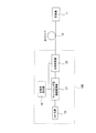
図1に、本実施形態に係る多波長光発生装置及び多波長光伝送システムの構成を示す。
本実施形態に係る多波長光伝送システムは、後述する本実施形態に係る多波長光発生装置10Aと、多波長光発生装置10Aと多波長光発生装置10Aからの多波長光を受信する受信機11とを結ぶ伝送用光ファイバ12とを有する。
[Embodiment 1]
FIG. 1 shows the configuration of a multiwavelength light generator and a multiwavelength light transmission system according to this embodiment.
The multi-wavelength optical transmission system according to this embodiment includes a multi-wavelength
そして、本実施形態に係る多波長光生装置10Aは、多波長光を発生するものであり、単一周波数のCW(Continuous Wave)光を発振するCW光源13と、CW光源13から発振した光を変調する変調器14と、変調器14に印加する電気信号を発生させる信号発生器15とを有し、信号発生器15は、光ファイバ12のブリルアン周波数シフト量fBの2倍の繰り返し周波数を持つ電気信号を発生させるものである。
The multi-wavelength
本実施形態では、単一周波数fSのCW光を発振するCW光源13に対し、変調器14において変調を行うようにしている。変調器14から出力される光は、変調器14に印加する電気信号の繰り返し周波数に応じた周波数間隔の線スペクトルを有する光となる。つまり、変調器14に印加する電気信号を発生させる信号発生器15の周波数を、光ファイバ12のブリルアン周波数シフト量fBの2倍に設定することで、SBSを抑圧する周波数間隔[2×fB]の多波長光を発生させることができる。
In this embodiment, the
本実施形態では、CW光源13の周波数が変わっても、発生する多波長光の周波数間隔は、信号発生器15における電気信号の繰り返し周波数が変わらなければ、一定である。つまり、従来技術では、光ファイバへ入射する光を発振する光源自体で光周波数制御が必要であったが、これが不要となった。このように、本実施形態では、精度が良く、安定している電気信号の繰り返し周波数の制御のみでよいので、光源自体での光周波数制御と比較して、精度良く、安定して、周波数間隔[2×fB]の多波長光を発生させることができる。
In this embodiment, even if the frequency of the CW
ここで、上記変調器としてマッハツェンダ型LN強度変調器を用い、波長多重数nを3とした場合の実験結果を示す。実験では、ブリルアン周波数シフト量fBが9.467GHzである分散補償ファイバ(DCF;Dispersion Compensation Fiber)10kmを用いた。又、正弦波発生器により発生させられる[2×fB]の周波数を持つ正弦波電気信号を用いて、マッハツェンダ型LN強度変調器でCW光を強度変調し、図2に示すように、3つの周波数を持つ多波長光を発生させ、これを入射光として用いた。発生した3つの多波長光を、図2において、左からPump1、Pump2、Pump3とする。 Here, an experimental result in the case where a Mach-Zehnder LN intensity modulator is used as the modulator and the number of wavelength multiplexing n is 3 is shown. In the experiment, a dispersion compensation fiber (DCF) 10 km having a Brillouin frequency shift amount f B of 9.467 GHz was used. Further, the CW light is intensity-modulated by a Mach-Zehnder LN intensity modulator using a sine wave electric signal having a frequency of [2 × f B ] generated by a sine wave generator, and as shown in FIG. Multi-wavelength light having one frequency was generated and used as incident light. The three generated multi-wavelength lights are referred to as Pump1, Pump2, and Pump3 from the left in FIG.
図3は、実験で用いたDCFに、単一周波数を有するCW光を入射した場合において、その入射光強度に対する透過光、反射光の強度を示している。入射光強度が8dBm以上の領域では、透過光強度が飽和し、透過光強度は約−1.6dBm以上に増加しないことがわかる。 FIG. 3 shows the intensities of transmitted light and reflected light with respect to the incident light intensity when CW light having a single frequency is incident on the DCF used in the experiment. It can be seen that in the region where the incident light intensity is 8 dBm or more, the transmitted light intensity is saturated and the transmitted light intensity does not increase to about −1.6 dBm or more.
一方、図4は、実験で用いたDCFに、図2に示した3つの多波長光を同時に入射した場合において、その入射光強度に対する透過光、反射光の強度を示している。図3の結果と比較すると、Pump1では、透過光強度が2.6dBmまで増加していることから、SBSが抑圧されていることが分かる。又、Pump2の場合、透過光強度が1.4dBmまで増加していることから、Pump2に対してもSBSの抑圧効果が確認できた。Pump3に関しては、図3の結果と同じであり、SBSの抑圧効果は無い。
On the other hand, FIG. 4 shows the intensities of transmitted light and reflected light with respect to the incident light intensity when the three multi-wavelength lights shown in FIG. 2 are simultaneously incident on the DCF used in the experiment. Compared with the result of FIG. 3, it can be seen that, in
実験で用いたDCFのブリルアン周波数シフト量fBの2倍からのずれをΔfとし、図2に示した3つの多波長光の周波数間隔をΔf=−100MHz〜+100MHzの範囲で変化させたときの各入射光の後方散乱光(ストークス光)強度を、図5に示す。図5において、Pump1、Pump2のグラフからわかるように、周波数間隔を[2×fB]とすることで(つまり、Δf=0)、ストークス光の抑圧効果が最大となっていることがわかる。 The deviation from twice the Brillouin frequency shift amount f B of the DCF used in the experiment is Δf, and the frequency interval of the three multi-wavelength lights shown in FIG. 2 is changed in the range of Δf = −100 MHz to +100 MHz. FIG. 5 shows the intensity of backscattered light (Stokes light) of each incident light. In FIG. 5, as can be seen from the graphs of Pump1 and Pump2, it can be seen that the suppression effect of Stokes light is maximized by setting the frequency interval to [2 × f B ] (that is, Δf = 0).
図6に、本実施形態に係る多波長光発生装置を用いた伝送特性の実験系を示す。
この実験系では、図2に示す3つの周波数を持つ多波長光を、正弦波電気信号を発生する正弦波発生器16に接続された前段のマッハツェンダ型LN強度変調器17で発生させている。そして、発生させた多波長光を、信号用パルスを発生するパルスパターン発生器18に接続された後段のマッハツェンダ型LN強度変調器19において強度変調を行い、2.5GbpsのNRZ信号を3つ発生させた。これを、光増幅器20によって20dBmまで増幅し、ブリルアン周波数シフト量fBが9.467GHzである光ファイバ12(分散補償ファイバ(DCF)10km)へ入射した。
FIG. 6 shows an experimental system of transmission characteristics using the multi-wavelength light generator according to this embodiment.
In this experimental system, multi-wavelength light having three frequencies shown in FIG. 2 is generated by a Mach-Zehnder type
光ファイバ12(DCF)からの出力光のうち、最も短波長側の光を光フィルタ21で取り出し、ビット誤り率(BER)を測定結果した。その測定結果を図7に示す。図7において、「抑圧有り」の場合は、発生した3つの光の周波数間隔を[2×fB]とし、「抑圧無し」の場合は、[2×fB−100MHz]とした。なお、「Back to back」は、DCFを実験系から取り除いた場合のBERである。この実験の結果、SBSを抑圧しない場合はエラーフロアが観測されたが、周波数間隔Δfを[2×fB]とすることで、「Back to back」の特性と同様の結果が得られた。このように、本実施形態を用いることにより、SBS抑圧効果が安定して得られることが分かる。
Of the output light from the optical fiber 12 (DCF), the light with the shortest wavelength was extracted by the
〔実施形態2〕
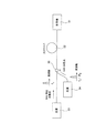
図8に、本実施形態に係る多波長光発生装置及び多波長光伝送システムの構成を示す。
本実施形態に係る多波長光伝送システムは、後述する本実施形態に係る多波長光発生装置10Bと、多波長光発生装置10Bと多波長光発生装置10Bからの多波長光を受信する受信機11とを結ぶ伝送用光ファイバ12とを有する。つまり、多波長光発生装置10Bの構成が、実施形態1に係る多波長光発生装置10Aと相違する。従って、実施形態1における構成と同等のものには同じ符号を付し、重複する説明は省略する。
[Embodiment 2]
FIG. 8 shows configurations of the multi-wavelength light generator and the multi-wavelength optical transmission system according to the present embodiment.
The multi-wavelength light transmission system according to this embodiment includes a multi-wavelength
本実施形態に係る多波長光生装置10Bも、多波長光を発生するものであり、図8に示すように、CW光源13と、CW光源13から発振した光の強度を変調するマッハツェンダ型強度変調器17と、マッハツェンダ型強度変調器17で変調した光の位相を変調する位相変調器22と、マッハツェンダ型強度変調器17及び位相変調器22に印加する正弦波電気信号を発生させる正弦波発生器16とを有し、正弦波発生器16は、光ファイバ12のブリルアン周波数シフト量fBの2倍の繰り返し周波数を持つ正弦波電気信号を発生させるものである。
The multi-wavelength
つまり、本実施例に係る多波長光生装置10Bは、実施形態1に係る多波長光発生装置10Aにおいて、変調器14をマッハツェンダ型強度変調器17及び位相変調器22とし、信号発生器15を正弦波発生器16としたものである。
That is, the multi-wavelength
従って、本実施形態に係る多波長光発生装置及び多波長光伝送システムは、実施形態1に係る多波長光発生装置及び多波長光伝送システムと同等の効果を得ることができる。 Therefore, the multi-wavelength light generation apparatus and the multi-wavelength light transmission system according to the present embodiment can obtain the same effects as the multi-wavelength light generation apparatus and the multi-wavelength light transmission system according to the first embodiment.
加えて、本実施例に係る多波長光生装置10Bでは、上記構成をとることにより、マッハツェンダ型強度変調器17及び位相変調器22に印加する正弦波発生器16の電気信号の振幅を増加させるだけで、発生する各線スペクトルの数を増加させることができ、かつ、発生する線スペクトルの強度偏差を少なくすることができるため、波長多重数の大きな伝送システムの多波長光源にも適用することができる(非特許文献5)。
In addition, in the multi-wavelength
〔実施形態3〕
図9に、本実施形態に係る多波長光発生装置及び多波長光伝送システムの構成を示す。
本実施形態に係る多波長光伝送システムは、後述する本実施形態に係る多波長光発生装置10Cと、多波長光発生装置10Cと多波長光発生装置10Cからの多波長光を受信する受信機11とを結ぶ伝送用光ファイバ12とを有する。つまり、多波長光発生装置10Cの構成が、実施形態1に係る多波長光発生装置10A、実施形態2に係る多波長光発生装置10Bと相違する。従って、実施形態1、2における構成と同等のものには同じ符号を付し、重複する説明は省略する。
[Embodiment 3]
FIG. 9 shows configurations of the multi-wavelength light generator and the multi-wavelength optical transmission system according to this embodiment.
The multi-wavelength optical transmission system according to this embodiment includes a multi-wavelength
本実施形態に係る多波長光生装置10Cも、多波長光を発生するものであり、図9に示すように、複数の線スペクトルからなる光を発振するモード同期レーザ24と、モード同期レーザ24内の変調器に印加する電気信号を発生させる信号発生器23とを有し、信号発生器23は、光ファイバ12のブリルアン周波数シフト量fBの2倍の繰り返し周波数を持つ電気信号を発生させるものである。
The multi-wavelength
モード同期レーザ24から発振される光パルスのスペクトルは、印可される電気信号のパルスの繰り返し周波数と一致した間隔で並ぶ線スペクトルからなる。従って、モード同期レーザ24のキャビティ内に設置してある変調器に、信号発生器23から印加する電気信号の周波数を、光ファイバ12のブリルアン周波数シフト量fBの2倍とすることで、各線スペクトルの間隔が光ファイバ12のブリルアン周波数シフト量fBの2倍となり、SBSを抑圧することができる多波長光を発生することができる。
The spectrum of the optical pulse oscillated from the mode-locked
上記構成により、本実施形態に係る多波長光発生装置及び多波長光伝送システムは、実施形態1、2に係る多波長光発生装置及び多波長光伝送システムと同等の効果を得ることができる。
With the above configuration, the multi-wavelength light generation apparatus and the multi-wavelength light transmission system according to this embodiment can obtain the same effects as the multi-wavelength light generation apparatus and the multi-wavelength light transmission system according to
なお、発生した多波長光を光ファイバ12へ入射する前に、多波長光発生用光ファイバへ入射し、非線形効果を起こすことで、発生する線スペクトル数を増加させることができる(非特許文献6)。
In addition, before the generated multi-wavelength light is incident on the
〔他の実施形態〕
SBSを抑圧する技術として、本発明で用いた技術の他に、入射信号に位相変調を加え、入射信号のスペクトル幅を広げる技術があるが、本発明は、この技術と組み合わせることが可能であり、更なるSBS抑圧効果を実現することができる。
[Other Embodiments]
As a technique for suppressing SBS, in addition to the technique used in the present invention, there is a technique of adding phase modulation to an incident signal to widen the spectrum width of the incident signal. However, the present invention can be combined with this technique. Thus, a further SBS suppression effect can be realized.
又、本発明は、上記実施形態例そのままに限定されるものではなく、実施段階ではその要旨を逸脱しない範囲で構成要素を変形して具体化できる。又、上記実施形態例に開示されている複数の構成要素の適宜な組合せにより種々の発明を形成できる。例えば、実施形態例に示される全構成要素からいくつかの構成要素を削除しても良い。更に、異なる実施形態例に亘る構成要素を適宜組み合わせても良い。 The present invention is not limited to the above-described embodiment as it is, and can be embodied by modifying the constituent elements without departing from the scope of the invention in the implementation stage. In addition, various inventions can be formed by appropriately combining a plurality of constituent elements disclosed in the above embodiment. For example, some components may be deleted from all the components shown in the embodiment. Furthermore, constituent elements over different embodiment examples may be appropriately combined.
本発明は、誘導ブリルアン散乱(SBS)の発生を抑圧することが可能であり、光ファイバに入射することのできる光信号の強度を増加させることができ、伝送システムにおいて、長距離伝送を実現することができる。 The present invention can suppress the occurrence of stimulated Brillouin scattering (SBS), increase the intensity of an optical signal that can be incident on an optical fiber, and realize long-distance transmission in a transmission system. be able to.
10A、10B、10C 多波長光発生装置
11 受信機
12 光ファイバ
13 CW光源
14 変調器
15 信号発生器
16 正弦波発生器
17 マッハツェンダ型強度変調器
18 パルスパターン発生器
19 マッハツェンダ型強度変調器
20 光増幅器
21 光フィルタ
22 位相変調器
23 信号発生器
24 モード同期レーザ
10A, 10B, 10C
Claims (6)
単一周波数の光を発振するCW光源と、
前記CW光源から発振した光を変調する変調器と、
当該多波長光発生装置の伝送対象となる光ファイバのブリルアン周波数シフト量の2倍の周波数を持つ電気信号を発生させて、前記変調器に印加する信号発生器とを有することを特徴とする多波長光発生装置。 In a multi-wavelength light generator that generates multi-wavelength light,
A CW light source that oscillates light of a single frequency;
A modulator for modulating light oscillated from the CW light source;
And a signal generator for generating an electric signal having a frequency twice as large as a Brillouin frequency shift amount of an optical fiber to be transmitted by the multi-wavelength light generator and applying the electric signal to the modulator. Wavelength light generator.
前記変調器を、前記CW光源から発振した光の強度を変調するマッハツェンダ型強度変調器と、前記マッハツェンダ型強度変調器で変調した光の位相を変調する位相変調器とし、
前記信号発生器を、前記光ファイバのブリルアン周波数シフト量の2倍の周波数を持つ正弦波電気信号を発生させて、前記マッハツェンダ型強度変調器及び前記位相変調器に印加する正弦波発生器としたことを特徴とする多波長光発生装置。 The multi-wavelength light generator according to claim 1,
The modulator is a Mach-Zehnder type intensity modulator that modulates the intensity of light oscillated from the CW light source, and a phase modulator that modulates the phase of light modulated by the Mach-Zehnder type intensity modulator,
The signal generator is a sine wave generator that generates a sine wave electric signal having a frequency twice the Brillouin frequency shift amount of the optical fiber and applies the sine wave electric signal to the Mach-Zehnder intensity modulator and the phase modulator. The multi-wavelength light generator characterized by the above-mentioned.
複数の線スペクトルからなる光を発振するモード同期レーザと、
当該多波長光発生装置の伝送対象となる光ファイバのブリルアン周波数シフト量の2倍の周波数を持つ電気信号を発生させて、前記モード同期レーザ内の変調器に印加する信号発生器とを有することを特徴とする多波長光発生装置。 In a multi-wavelength light generator that generates multi-wavelength light,
A mode-locked laser that oscillates light having a plurality of line spectra;
A signal generator for generating an electric signal having a frequency twice the Brillouin frequency shift amount of an optical fiber to be transmitted by the multi-wavelength light generator and applying the electric signal to the modulator in the mode-locked laser; A multi-wavelength light generator characterized by the above.
前記多波長光発生装置と前記多波長光発生装置が発生した多波長光を受信する受信機とを結ぶ光ファイバとを有する多波長光伝送システムにおいて、
前記多波長光発生装置は、
単一周波数の光を発振するCW光源と、
前記CW光源から発振した光を変調する変調器と、
前記光ファイバのブリルアン周波数シフト量の2倍の周波数を持つ電気信号を発生させて、前記変調器に印加する信号発生器とを有することを特徴とする多波長光伝送システム。 A multi-wavelength light generator for generating multi-wavelength light;
In a multi-wavelength optical transmission system having an optical fiber connecting the multi-wavelength light generator and a receiver that receives the multi-wavelength light generated by the multi-wavelength light generator,
The multi-wavelength light generator is
A CW light source that oscillates light of a single frequency;
A modulator for modulating light oscillated from the CW light source;
A multi-wavelength optical transmission system comprising: a signal generator that generates an electric signal having a frequency twice as large as a Brillouin frequency shift amount of the optical fiber and applies the signal to the modulator.
前記変調器を、前記CW光源から発振した光の強度を変調するマッハツェンダ型強度変調器と、前記マッハツェンダ型強度変調器で変調した光の位相を変調する位相変調器とし、
前記信号発生器を、前記光ファイバのブリルアン周波数シフト量の2倍の周波数を持つ正弦波電気信号を発生させて、前記マッハツェンダ型強度変調器及び前記位相変調器に印加する正弦波発生器としたことを特徴とする多波長光伝送システム。 The multi-wavelength optical transmission system according to claim 4,
The modulator is a Mach-Zehnder type intensity modulator that modulates the intensity of light oscillated from the CW light source, and a phase modulator that modulates the phase of light modulated by the Mach-Zehnder type intensity modulator,
The signal generator is a sine wave generator that generates a sine wave electric signal having a frequency twice the Brillouin frequency shift amount of the optical fiber and applies the sine wave electric signal to the Mach-Zehnder intensity modulator and the phase modulator. A multi-wavelength optical transmission system.
前記多波長光発生装置と前記多波長光発生装置が発生した多波長光を受信する受信機とを結ぶ光ファイバとを有する多波長光伝送システムにおいて、
前記多波長光発生装置は、
複数の線スペクトルからなる光を発振するモード同期レーザと、
前記光ファイバのブリルアン周波数シフト量の2倍の周波数を持つ電気信号を発生させて、前記モード同期レーザ内の変調器に印加する信号発生器とを有することを特徴とする多波長光伝送システム。 A multi-wavelength light generator for generating multi-wavelength light;
In a multi-wavelength optical transmission system having an optical fiber connecting the multi-wavelength light generator and a receiver that receives the multi-wavelength light generated by the multi-wavelength light generator,
The multi-wavelength light generator is
A mode-locked laser that oscillates light having a plurality of line spectra;
A multi-wavelength optical transmission system comprising: a signal generator that generates an electric signal having a frequency twice as large as a Brillouin frequency shift amount of the optical fiber and applies the signal to a modulator in the mode-locked laser.
Priority Applications (1)
| Application Number | Priority Date | Filing Date | Title |
|---|---|---|---|
| JP2008213422A JP5000606B2 (en) | 2008-08-22 | 2008-08-22 | Multi-wavelength light generator and multi-wavelength light transmission system |
Applications Claiming Priority (1)
| Application Number | Priority Date | Filing Date | Title |
|---|---|---|---|
| JP2008213422A JP5000606B2 (en) | 2008-08-22 | 2008-08-22 | Multi-wavelength light generator and multi-wavelength light transmission system |
Publications (2)
| Publication Number | Publication Date |
|---|---|
| JP2010050758A true JP2010050758A (en) | 2010-03-04 |
| JP5000606B2 JP5000606B2 (en) | 2012-08-15 |
Family
ID=42067475
Family Applications (1)
| Application Number | Title | Priority Date | Filing Date |
|---|---|---|---|
| JP2008213422A Expired - Fee Related JP5000606B2 (en) | 2008-08-22 | 2008-08-22 | Multi-wavelength light generator and multi-wavelength light transmission system |
Country Status (1)
| Country | Link |
|---|---|
| JP (1) | JP5000606B2 (en) |
Cited By (4)
| Publication number | Priority date | Publication date | Assignee | Title |
|---|---|---|---|---|
| JP2011182924A (en) * | 2010-03-08 | 2011-09-22 | Sophia Co Ltd | Game machine |
| WO2015191124A3 (en) * | 2014-03-06 | 2016-03-31 | California Institute Of Technology | Stable microwave-frequency source based on cascaded brillouin lasers |
| WO2016138291A1 (en) * | 2015-02-26 | 2016-09-01 | California Institute Of Technology | Optical frequency divider based on an electro-optical-modulator frequency comb |
| US9537571B2 (en) | 2014-01-24 | 2017-01-03 | California Institute Of Technology | Dual-frequency optical source |
Citations (2)
| Publication number | Priority date | Publication date | Assignee | Title |
|---|---|---|---|---|
| JP2002082323A (en) * | 2000-07-07 | 2002-03-22 | Nippon Telegr & Teleph Corp <Ntt> | Multiple wavelength batch generator |
| JP2006005531A (en) * | 2004-06-16 | 2006-01-05 | Nippon Telegr & Teleph Corp <Ntt> | Multichannel optical transmitter |
-
2008
- 2008-08-22 JP JP2008213422A patent/JP5000606B2/en not_active Expired - Fee Related
Patent Citations (2)
| Publication number | Priority date | Publication date | Assignee | Title |
|---|---|---|---|---|
| JP2002082323A (en) * | 2000-07-07 | 2002-03-22 | Nippon Telegr & Teleph Corp <Ntt> | Multiple wavelength batch generator |
| JP2006005531A (en) * | 2004-06-16 | 2006-01-05 | Nippon Telegr & Teleph Corp <Ntt> | Multichannel optical transmitter |
Cited By (7)
| Publication number | Priority date | Publication date | Assignee | Title |
|---|---|---|---|---|
| JP2011182924A (en) * | 2010-03-08 | 2011-09-22 | Sophia Co Ltd | Game machine |
| US9537571B2 (en) | 2014-01-24 | 2017-01-03 | California Institute Of Technology | Dual-frequency optical source |
| US10009103B2 (en) | 2014-01-24 | 2018-06-26 | California Institute Of Technology | Stabilized microwave-frequency source |
| WO2015191124A3 (en) * | 2014-03-06 | 2016-03-31 | California Institute Of Technology | Stable microwave-frequency source based on cascaded brillouin lasers |
| US9595918B2 (en) | 2014-03-06 | 2017-03-14 | California Institute Of Technology | Stable microwave-frequency source based on cascaded brillouin lasers |
| WO2016138291A1 (en) * | 2015-02-26 | 2016-09-01 | California Institute Of Technology | Optical frequency divider based on an electro-optical-modulator frequency comb |
| US9905999B2 (en) | 2015-02-26 | 2018-02-27 | California Institute Of Technology | Optical frequency divider based on an electro-optical-modulator frequency comb |
Also Published As
| Publication number | Publication date |
|---|---|
| JP5000606B2 (en) | 2012-08-15 |
Similar Documents
| Publication | Publication Date | Title |
|---|---|---|
| Min et al. | Flat amplitude equal spacing 798-channel Rayleigh-assisted Brillouin/Raman multiwavelength comb generation in dispersion compensating fiber | |
| JP2009177641A (en) | Optical signal processing apparatus, optical receiving apparatus, and optical relay apparatus | |
| Al-Mansoori et al. | Multiwavelength L-band Brillouin–Erbium comb fiber laser utilizing nonlinear amplifying loop mirror | |
| Lin et al. | Tunable dual-wavelength erbium-doped fiber ring laser covering both C-band and L-band for high-speed communications | |
| JP5000606B2 (en) | Multi-wavelength light generator and multi-wavelength light transmission system | |
| JP2008216716A (en) | Supercontinuum light source | |
| JP2011142544A (en) | Optical feeding light source and optical feeding rof system using the same | |
| Ahmad et al. | Tunable, low frequency microwave generation from AWG based closely-spaced dual-wavelength single-longitudinal-mode fibre laser | |
| Wang et al. | Seed-injected, actively Q-switched fiber ring laser using an AOM of zero-order transmission | |
| CN109643878B (en) | Spectrum narrowing module, refined spectral line apparatus and associated methods | |
| Yi et al. | 10 Gb/s symmetric WDM-PON using stable multi-longitudinal mode Brillouin/SOA fiber laser as upstream colorless source | |
| CN114336227A (en) | Microwave signal generating device based on low-distortion dissipative Kerr soliton | |
| Cao et al. | Wavelength converting optical access network for 10Gbit/s PON | |
| US8014428B2 (en) | Mode-locked laser | |
| Morohashi et al. | 1 THz-bandwidth optical comb generation using Mach-Zehnder-modulator-based flat comb generator with optical feedback loop | |
| Ishizawa et al. | Carrier-envelope-offset locking of 25-GHz EOM comb based on a free-running CW Laser Diode | |
| Al-Taiy et al. | Ultra-narrow line-width, stable and widely tuneable laser source for coherent optical communication systems | |
| Kharraz et al. | Performance enhancement of pre-spectrum slicing technique for wavelength conversion | |
| Ali et al. | Single-pump multiwavelength hybrid Raman-EDF laser using a non-adiabatic microfiber interferometer | |
| Lee et al. | Side-mode suppressed multiwavelength fiber laser and broadcast transmission | |
| Ajiya et al. | Multiwavelength Brillouin/erbium fiber laser utilizing virtual reflectivity in dispersion compensating fiber | |
| JP5788814B2 (en) | Raman amplifier excitation apparatus and Raman amplifier excitation method | |
| Yamatoya et al. | Optical preamplifier using inverted signal of amplified spontaneous emission in saturated semiconductor optical amplifier | |
| Ismail et al. | Multi-wavelength Brillouin Raman Erbium Fiber Laser utilizing Captured Residual Raman Pump Power | |
| JP5026366B2 (en) | Wavelength multiplexed optical transmitter |
Legal Events
| Date | Code | Title | Description |
|---|---|---|---|
| A621 | Written request for application examination |
Free format text: JAPANESE INTERMEDIATE CODE: A621 Effective date: 20100727 |
|
| A977 | Report on retrieval |
Free format text: JAPANESE INTERMEDIATE CODE: A971007 Effective date: 20111213 |
|
| A131 | Notification of reasons for refusal |
Free format text: JAPANESE INTERMEDIATE CODE: A131 Effective date: 20111220 |
|
| A521 | Written amendment |
Free format text: JAPANESE INTERMEDIATE CODE: A523 Effective date: 20120220 |
|
| TRDD | Decision of grant or rejection written | ||
| A01 | Written decision to grant a patent or to grant a registration (utility model) |
Free format text: JAPANESE INTERMEDIATE CODE: A01 Effective date: 20120515 |
|
| A01 | Written decision to grant a patent or to grant a registration (utility model) |
Free format text: JAPANESE INTERMEDIATE CODE: A01 |
|
| A61 | First payment of annual fees (during grant procedure) |
Free format text: JAPANESE INTERMEDIATE CODE: A61 Effective date: 20120516 |
|
| R150 | Certificate of patent or registration of utility model |
Free format text: JAPANESE INTERMEDIATE CODE: R150 |
|
| FPAY | Renewal fee payment (event date is renewal date of database) |
Free format text: PAYMENT UNTIL: 20150525 Year of fee payment: 3 |
|
| S531 | Written request for registration of change of domicile |
Free format text: JAPANESE INTERMEDIATE CODE: R313531 |
|
| R350 | Written notification of registration of transfer |
Free format text: JAPANESE INTERMEDIATE CODE: R350 |
|
| LAPS | Cancellation because of no payment of annual fees |