JP2010048264A - Cutoff system - Google Patents
Cutoff system Download PDFInfo
- Publication number
- JP2010048264A JP2010048264A JP2008210310A JP2008210310A JP2010048264A JP 2010048264 A JP2010048264 A JP 2010048264A JP 2008210310 A JP2008210310 A JP 2008210310A JP 2008210310 A JP2008210310 A JP 2008210310A JP 2010048264 A JP2010048264 A JP 2010048264A
- Authority
- JP
- Japan
- Prior art keywords
- information
- control device
- drive control
- aperture
- shut
- Prior art date
- Legal status (The legal status is an assumption and is not a legal conclusion. Google has not performed a legal analysis and makes no representation as to the accuracy of the status listed.)
- Granted
Links
- 230000008569 process Effects 0.000 claims description 33
- 238000000034 method Methods 0.000 claims description 31
- 238000001514 detection method Methods 0.000 claims description 16
- 230000004044 response Effects 0.000 claims description 8
- 230000005540 biological transmission Effects 0.000 claims description 7
- 230000000903 blocking effect Effects 0.000 claims description 6
- 238000012545 processing Methods 0.000 abstract description 14
- 238000007689 inspection Methods 0.000 abstract description 7
- 238000012790 confirmation Methods 0.000 abstract description 4
- 239000000284 extract Substances 0.000 abstract description 2
- 238000004519 manufacturing process Methods 0.000 description 37
- 238000004891 communication Methods 0.000 description 25
- 230000006870 function Effects 0.000 description 10
- 230000007246 mechanism Effects 0.000 description 6
- 238000010586 diagram Methods 0.000 description 5
- 238000009434 installation Methods 0.000 description 3
- 238000000605 extraction Methods 0.000 description 2
- 238000005192 partition Methods 0.000 description 2
- 230000009467 reduction Effects 0.000 description 2
- 230000005856 abnormality Effects 0.000 description 1
- 230000009471 action Effects 0.000 description 1
- 230000002457 bidirectional effect Effects 0.000 description 1
- 230000008859 change Effects 0.000 description 1
- 238000012423 maintenance Methods 0.000 description 1
- 239000000203 mixture Substances 0.000 description 1
- 238000012986 modification Methods 0.000 description 1
- 230000004048 modification Effects 0.000 description 1
- 238000000638 solvent extraction Methods 0.000 description 1
- 238000012360 testing method Methods 0.000 description 1
Images


Landscapes
- Indication Of The Valve Opening Or Closing Status (AREA)
Abstract
Description
本発明は、口径が異なる複数種類の遮断弁の駆動を制御する駆動制御装置に電力を供給し且つ前記駆動制御装置との間で通信を行う操作装置を有する遮断システムに関するものである。 The present invention relates to a shut-off system having an operation device that supplies power to a drive control device that controls driving of a plurality of types of shut-off valves having different diameters and communicates with the drive control device.
ガス遮断弁は、ガス配管の途中にフランジを介して挿入接続されるハウジングと、そのハウジングに着脱可能に設けられる弁本体及び弁駆動機構を有して構成している。例えば、特許文献1に記載されているガス遮断弁は、ガス配管に接続される一対のフランジを有するハウジング内部を、一方のフランジ側配管に連通する流路空間と他方のフランジ側配管に連通する流路空間を仕切って隔壁を設け、その隔壁に形成された貫通穴にリング状のノズルを気密に装着し、そのノズルに対して平板状の弁体を接続可能に設け、遮断指令に基づいて弁体をノズルに押し付けて弁ハウジングのガスの入口側流路と出口側流路を遮断するように構成されている。 The gas shut-off valve has a housing that is inserted and connected via a flange in the middle of the gas pipe, and a valve body and a valve drive mechanism that are detachably provided in the housing. For example, a gas shut-off valve described in Patent Document 1 communicates the interior of a housing having a pair of flanges connected to a gas pipe with a flow passage space communicating with one flange side pipe and the other flange side pipe. A partition wall is provided by partitioning the flow path space, and a ring-shaped nozzle is airtightly attached to a through hole formed in the partition wall, and a flat plate-like valve body is provided to be connectable to the nozzle. The valve body is pressed against the nozzle so as to block the gas inlet-side flow path and the outlet-side flow path of the valve housing.
また、ガス遮断弁は、その機能を保持するために、一定期間(例えば、10年等)ごとに交換或いは保守点検することが必要となる。そのため、特許文献2に示すガス遮断弁は、ガス配管に接続されたハウジングを交換する必要性がほとんどないことに鑑み、ガス遮断弁の交換等が必要な部品を含む主要部をユニット化して、そのユニットの部分のみを交換可能な構成とすることで、ガス遮断弁の交換等の作業時には、ガス配管に接続されたハウジングを取り外さずに、遮断弁ユニットの基部をハウジングの取り付け座から取り外し、交換する新たな遮断弁ユニットをハウジングに装着することにより、ガス遮断弁の交換作業を終了できるようにしている。
上述したようにガス遮断弁は、遮断弁ユニットとハウジングとの交換が可能な構成となり、複数の設置場所、配管等の差異は複数種類の異なる遮断弁の口径を用意することで解消できることから、複数種類のハウジングに共通の遮断弁ユニットを用いることが可能となった。 As described above, the gas shut-off valve can be replaced with the shut-off valve unit and the housing, and differences in multiple installation locations, piping, etc. can be resolved by preparing different types of shut-off valve bores, A common shut-off valve unit can be used for multiple types of housings.
しかしながら、このように遮断弁ユニットの共通化を図る場合、遮断弁ユニットは例えば復帰漏洩確認、気密漏洩検査の時間等を遮断弁の口径に対応して設定する必要があった。そのため、遮断弁ユニットに操作器を接続し、その操作器から口径データを取得して各種設定を行う機能を遮断弁ユニットに設けたり、マグネットと磁力でONするスイッチを有する口径の自動確認する検出機構を遮断弁ユニットに設ける等が必要となり、この余計な構成、検出機構によって遮断弁ユニット等がコストアップしてしまうという問題があった。また、ガス遮断弁ごとに、その遮断弁の口径を遮断弁ユニットに登録、設定する作業が必要となったり、その口径を示す口径データを管理するシステムが必要となる。 However, when the shut-off valve unit is made common in this way, the shut-off valve unit needs to set, for example, the time for the return leak check and the airtight leak test corresponding to the diameter of the shut-off valve. For this reason, an operation device is connected to the shut-off valve unit, the bore size data is obtained from the operation device, and various settings are provided in the shut-off valve unit. It is necessary to provide a mechanism in the shut-off valve unit, and there is a problem that the cost of the shut-off valve unit and the like is increased due to this extra configuration and detection mechanism. In addition, for each gas shut-off valve, it is necessary to register and set the diameter of the shut-off valve in the shut-off valve unit, and a system for managing the bore diameter data indicating the diameter is required.
よって本発明は、上述した問題点に鑑み、遮断弁の口径を自動認識して、その口径に対応した処理を実行することができる遮断システムを提供することを課題としている。 Therefore, in view of the above-described problems, an object of the present invention is to provide a shutoff system capable of automatically recognizing the aperture of the shutoff valve and executing processing corresponding to the aperture.
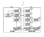
上記課題を解決するため本発明によりなされた請求項1記載の遮断システムは、図1の基本構成図に示すように、口径が異なる複数種類の遮断弁の駆動を制御する駆動制御装置20と、前記駆動制御装置20に電力を供給し且つ前記駆動制御装置20との間で通信を行う操作装置10と、を有する遮断システム1において、前記操作装置10が、前記駆動制御装置20の駆動対象となる遮断弁の口径を示す口径情報を記憶する口径情報記憶手段12と、前記口径情報記憶手段12が記憶している口径情報を前記駆動制御装置20に送信する口径情報送信手段11a1と、を有し、前記駆動制御装置20が、前記複数種類の遮断弁の各々に対応した複数種類の固有情報を記憶する固有情報記憶手段22aと、前記操作装置10の口径情報送信手段11a1が送信した口径情報を受信する口径情報受信手段21a1と、前記口径情報受信手段21a1が受信した口径情報に対応した前記固有情報を、前記複数種類の固有情報の中から抽出する固有情報抽出手段21a2と、前記固有情報抽出手段21a2が抽出した固有情報に基づいて、予め定められた所定処理を実行する所定処理実行手段21a3と、を有することを特徴とする。
In order to solve the above problems, the shut-off system according to claim 1, which is made according to the present invention, as shown in the basic configuration diagram of FIG. In the shut-off system 1 having an
上記請求項1に記載した本発明の遮断システムによれば、操作装置10は口径情報記憶手段12に記憶している口径情報を口径情報送信手段11a1によって駆動制御装置20に送信する。そして、駆動制御装置20は口径情報受信手段21a1によって口径情報を受信すると、該口径情報に対応した固有情報を固有情報記憶手段22aから固有情報抽出手段21a2が抽出する。駆動制御装置20は抽出した固有情報に基づいて例えば復帰漏洩確認、気密漏洩検査、等の所定処理を実行する。
According to the shutoff system of the present invention described in the first aspect, the
請求項2記載の発明は、図1の基本構成図に示すように、請求項1に記載の遮断システムにおいて、前記駆動制御装置20が、該駆動制御装置20に着脱自在の前記遮断弁と、前記装着された遮断弁に対応して登録された前記口径を示す登録口径情報を記憶する登録口径情報記憶手段22bと、前記登録口径情報記憶手段22bが記憶している登録口径情報を前記操作装置10に送信する登録口径情報送信手段21a4と、を有し、前記操作装置10が、前記駆動制御装置20の登録口径情報送信手段21a4が送信した登録口径情報を受信する登録口径情報受信手段11a2を有し、前記口径情報記憶手段12が、前記登録口径情報受信手段11a2によって受信した登録口径情報を前記口径情報として記憶する手段であることを特徴とする。
As shown in the basic configuration diagram of FIG. 1, the invention according to
上記請求項2に記載した本発明の遮断システムによれば、駆動制御装置20は装着された遮断弁に対応して登録された登録口径情報を登録口径情報記憶手段22bに記憶していると、その登録口径情報を登録口径情報送信手段21a4によって操作装置10に送信する。そして、操作装置10は、登録口径情報送信手段21a4が送信した登録口径情報を登録口径情報受信手段11a2によって受信すると、その登録口径情報を口径情報として口径情報記憶手段12に記憶する。
According to the shut-off system of the present invention described in
請求項3記載の発明は、図1の基本構成図に示すように、請求項1又は2に記載の遮断システムにおいて、前記駆動制御装置20が、該駆動制御装置20を識別するための識別情報を前記操作装置10に送信する識別情報送信手段21a5を有し、前記操作装置10が、前記識別情報を前記駆動制御装置20から受信する識別情報受信手段11a3と、前記受信した識別情報と前回受信した識別情報との比較結果に基づいて前記駆動制御装置20の交換を検出する交換検出手段11a4と、を有し、前記操作装置10の口径情報送信手段11a1が、前記交換検出手段11a4による交換の検出に応じて、前記口径情報を前記駆動制御装置20に送信する手段であることを特徴とする。
According to a third aspect of the present invention, as shown in the basic configuration diagram of FIG. 1, in the shutoff system according to the first or second aspect, the
上記請求項3に記載した本発明の遮断システムによれば、駆動制御装置20は識別情報送信手段21a5によって識別情報を操作装置10に送信すると、操作装置10は識別情報受信手段11a3によって駆動制御装置20から識別情報を受信すると、今回受信した識別情報と前回受信した識別情報との比較結果に基づいて、駆動制御装置20の交換が交換検出手段11a4によって検出する。操作装置10はその交換の検出に応じて、口径情報を駆動制御装置20に口径情報送信手段11a1によって送信する。
According to the shut-off system of the present invention described in claim 3, when the
以上説明したように請求項1に記載した本発明によれば、操作装置が記憶している口径情報を駆動制御装置に送信し、駆動制御装置が受信した口径情報に対応した固有情報を複数の固有情報から抽出し、該固有情報に基づいて所定処理を実行するようにしたことから、操作装置に口径情報を記憶させておくことで、駆動制御装置を交換しても遮断弁の口径情報を駆動制御装置に自動で認識させることができるため、駆動制御装置は遮断弁の口径に適した各種処理を行うことができ、作業者が駆動制御装置に口径を登録するという登録作業、通信により口径を登録するための装置等を不要とすることができる。従って、遮断弁の口径を誤って設定することがなるため、遮断弁に余計な口径検出機構を追加する必要がなくなり、遮断システムのコストアップを防止できる。 As described above, according to the first aspect of the present invention, the aperture information stored in the operating device is transmitted to the drive control device, and the unique information corresponding to the aperture information received by the drive control device is a plurality of pieces of unique information. Since the specific information is extracted from the specific information and predetermined processing is executed based on the specific information, the caliber information is stored in the operating device, so that the caliber information of the shut-off valve can be obtained even if the drive control device is replaced. Since the drive control device can automatically recognize it, the drive control device can perform various processes suitable for the aperture of the shut-off valve, and the operator can register the aperture in the drive control device through communication and registration. A device or the like for registering can be eliminated. Therefore, since the diameter of the shutoff valve can be set erroneously, there is no need to add an extra bore size detection mechanism to the shutoff valve, and the cost of the shutoff system can be prevented from increasing.
請求項2に記載した本発明によれば、駆動制御装置が記憶している登録口径情報を操作装置に送信し、操作装置がその受信した登録口径情報を口径情報として記憶するようにしたことから、遮断弁に対応した登録口径情報を操作装置に自動で記憶させることができるため、駆動制御装置が口径情報を記憶していない共通の駆動制御装置に交換されたときに、操作装置から共通の駆動制御装置に口径情報を送信して自動的に認識させることができる。よって、遮断弁の口径の登録を要することなく、駆動制御装置の共通化を図ることができるため、遮断システムのコストダウンに貢献することができる。 According to the second aspect of the present invention, the registered aperture information stored in the drive control device is transmitted to the operating device, and the operating device stores the received registered aperture information as the aperture information. Since the registered aperture information corresponding to the shut-off valve can be automatically stored in the operating device, when the drive control device is replaced with a common drive control device that does not store the aperture information, The aperture information can be transmitted to the drive control device for automatic recognition. Therefore, since it is possible to share the drive control device without requiring registration of the diameter of the shutoff valve, it is possible to contribute to the cost reduction of the shutoff system.
請求項3に記載した本発明によれば、駆動制御装置がその識別情報を操作装置に送信し、操作装置が今回受信した識別情報と前回受信した識別情報とを比較して駆動制御装置の交換を検出すると、その交換の検出に応じて記憶している口径情報を駆動制御装置に送信するようにしたことから、駆動制御装置の交換に応じて操作装置に記憶している口径情報を駆動制御装置に自動で記憶させることができるため、駆動制御装置が口径情報を記憶していない共通の駆動制御装置に交換されたときに、迅速に共通の駆動制御装置に制御対象となる遮断弁20Aの口径を自動的に認識させることができる。 According to the third aspect of the present invention, the drive control device transmits the identification information to the operating device, and the operating device compares the identification information received this time with the previously received identification information to replace the drive control device. Since the aperture information stored in response to the detection of the exchange is transmitted to the drive control device, the aperture information stored in the operating device is driven to be controlled in accordance with the replacement of the drive control device. Since the device can be automatically stored, when the drive control device is replaced with a common drive control device that does not store the aperture information, the common drive control device can quickly control the shutoff valve 20A to be controlled. The aperture can be recognized automatically.
以下、本発明に係る遮断システムの一実施形態を、図1〜図8の図面を参照して以下に説明する。 Hereinafter, an embodiment of a blocking system according to the present invention will be described below with reference to the drawings of FIGS.
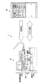
図2〜3において、遮断システム1は、宅内等に設けられる操作装置10と、ガス供給路の配管5に組み込まれ且つ操作装置10の制御等によって配管5を遮断する遮断弁ユニット20と、を有して構成している。そして、操作装置10と遮断弁ユニット20は、通信線3を介して、双方向のシリアル通信可能に接続されている。また、操作装置10は、遮断弁ユニット20と電気的に接続されており、外部電源等から供給される電力によって動作すると共に、その電力を遮断弁ユニット20に供給している。
2 to 3, the shut-off system 1 includes an
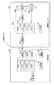
操作装置10は、図3に示すように、予め定められたプログラムに従って動作するマイクロプロセッサ(MPU)11を有している。MPU11は、周知のように、予め定めたプログラムに従って各種の処理や制御などを行う中央演算処理装置(CPU)11a、CPU11aのためのプログラム等を格納した読み出し専用のメモリであるROM11b、各種のデータを格納するとともにCPU11aの処理作業に必要なエリアを有する読み出し書き込み自在のメモリであるRAM11c等を有して構成している。
As shown in FIG. 3, the
ROM11bは、上述した図1に示す請求項中の口径情報送信手段11a1、登録口径情報受信手段11a2、識別情報受信手段11a3、交換検出手段11a4、等の各種手段として、CPU11aを機能させるための各種プログラム等を記憶している。
The
操作装置10はさらに、メモリ部12と、通信部13と、設定部16と、表示部17と、操作部18と、電力供給部19と、を有しており、各々はMPU11と電気的に接続されている。
The
メモリ部12は、電力供給が断たれた場合でも、格納された各種データの保持が可能であり、CPU11aの処理作業に必要な各種格納エリアを有する電気的消去/書き換え可能なメモリ(EEPROM)等が用いられる。このメモリ部12は、図4に示すように、操作装置製造年月121、操作装置使用時間122、遮断弁ユニット製造年月123、遮断弁使用時間124、駆動制御装置使用時間125、遮断弁の口径126、等の各種データを記憶している。
The
操作装置製造年月121は、操作装置10が製造された製造年月(例えば、年のみでも可)データが設定される。例えば「1009」の場合、2010年9月を示している。操作装置使用時間122は、設置されてからの使用時間データが定期的に書き込まれる。遮断弁ユニット製造年月123は、遮断弁ユニット10から取得した製造年月データ等が設定される。遮断弁使用時間124は、後述する遮断弁20Aの使用時間データが定期的に書き込まれる。駆動制御装置使用時間125は、後述する駆動制御装置20bの使用時間データが定期的に書き込まれる。
The operation
遮断弁20Aの口径126は、遮断弁ユニット20から取得した口径データが設定される。口径データの一例としては、口径20〜25が「1」、口径32〜40が「2」、口径50が「3」、口径80が「4」となっている。
The bore diameter data acquired from the
通信部13は、通信線3と電気的に接続されると共に、MPU11と電気的に接続されている。通信部13は、通信線3を介してMPU11から入力される各種電文を示す信号を遮断弁ユニット20に送信すると共に、通信線3を介して遮断弁ユニット20から受信した信号が示す電文をMPU11に出力する。
The
設定部16は、遮断弁ユニット20の遮断弁26を通信異常発生時に遮断するか否かがON/OFFを選択するためのディップスイッチを有している。設定部16は、操作装置10のケース本体で隠され且つシステム管理者等によってのみ操作が可能な構成となっている。設定部16は、前記ディップスイッチが操作装置10の設置時、ガス需要者からの設定変更が要求されたとき等にシステム管理者等によって設定され、MPU11によってディップスイッチの設定状態が検出される。
The setting
表示部17は、MPU11と電気的に接続されており、MPU11からの要求に応じて表示が可能な構成となっている。表示部17は、図示しないが、警報器故障、停電検知、故障検知、検査中等の各々に対応したLEDの点灯によって表示状態となり、LEDの消灯によって非表示状態となる。
The
操作部18は、MPU11と電気的に接続されており、利用者、作業者等に各種データの入力、選択を行わせる、ための複数の操作スイッチと、弁開スイッチと、弁閉スイッチと、を有している。操作部18は、それらの操作スイッチに対する操作に応じた操作信号をMPU11に出力する。そして、操作部18の弁開スイッチ又は弁閉スイッチが操作されると、MPU11は通信線3を介して遮断(弁閉)要求信号又は開放(弁開)要求信号を遮断弁ユニット20に送信する。
The
このように構成した操作装置10のCPU11aは、外部電源等からの電力供給によって起動されると、所定のプログラムを実行することで、電力供給部19を制御してその電力の一部を遮断弁ユニット20に供給する。即ち、電力供給部19は、遮断弁ユニット20に所定の電力を供給するための回路等によって構成している。このような電力の供給により、遮断弁ユニット20は起動されて動作可能状態となる。
When the
次に、上述した操作装置10のCPU11aの口径情報管理処理プログラムの実行による口径情報管理処理の一例を、図6に示すフローチャートを参照して以下に説明する。なお、この口径情報管理処理は、操作装置10の電源断、上位処理からの強制終了等に応じて処理を終了することを前提としている。
Next, an example of the aperture information management process by executing the aperture information management process program of the
CPU11aによって口径情報管理処理プログラムが実行されると、ステップS11において、通信部13を介して駆動制御装置20Bから遮断弁ユニット製造年月データを有する識別情報を受信したか否かが判定される。識別情報を受信していないと判定された場合(S11でN)、ステップS12において、通信部13を介して駆動制御装置20Bから口径情報を受信したか否かが判定される。口径情報を受信していないと判定された場合(S12でN)、ステップS11に戻り、一連の処理が繰り返される。
When the aperture information management processing program is executed by the
一方、ステップS12で口径情報を受信したと判定された場合(S12でY)、ステップS13において、その口径情報がメモリ部12に記憶されることで、口径情報の口径データがメモリ部12の口径126に設定され、その後ステップS11に戻り、一連の処理が繰り返される。
On the other hand, when it is determined that the aperture information is received in step S12 (Y in S12), the aperture information is stored in the
また、ステップS11で識別情報を受信したと判定された場合(S11でY:識別情報受信手段)、識別情報がRAM11cに時系列的に記憶され、ステップS14(交換検出手段)において、今回受信した識別情報と前回受信した識別情報とが同一であるか否かが判定される。具体的には、識別情報の遮断弁ユニット製造年月データとメモリ部12の遮断弁ユニット製造年月123に設定されたデータとを比較する。
If it is determined in step S11 that the identification information has been received (Y in S11: identification information receiving means), the identification information is stored in the
ステップS14で前回と同一であると判定された場合(S14でY)、遮断弁ユニット20側で交換が発生していないと判定し、ステップS11に戻り、一連の処理が繰り返される。一方、前回と同一ではないと判定された場合(S14でN)、遮断弁ユニット20側で交換が発生したと判定し、ステップS15に進む。
If it is determined in step S14 that it is the same as the previous time (Y in S14), it is determined that no replacement has occurred on the
ステップS15において、受信した識別情報がメモリ部12に記憶されることで、メモリ部12の遮断弁ユニット製造年月123に識別情報の遮断弁ユニット製造年月データが設定され、その後ステップS16(口径情報送信手段)において、メモリ部12の遮断弁20Aの口径126に設定されている口径データとメモリ部12が記憶している配管容積データを有する口径情報が作成され、該口径情報が通信部13を介して駆動制御装置20Bに送信され、その後ステップS11に戻り、一連の処理が繰り返される。
In step S15, the received identification information is stored in the
以上説明した図6に示す口径情報管理処理をCPU11aが実行することで、上述した図1に示す請求項中の口径情報送信手段11a1、識別情報受信手段11a3、交換検出手段11a4、等としてCPU11aが機能することになる。そして、図6に示すフローチャート中のステップS11が識別情報受信手段11a3、ステップS14が交換検出手段11a4、ステップS16が口径情報送信手段11a1にそれぞれ相当している。
When the
また、CPU11の登録口径情報受信手段11a2は、通信部13を介して駆動制御装置20Bから受信した登録口径情報を受信する。そして、本実施形態では、登録口径情報受信手段11a2がメモリ部12の遮断弁20Aの口径126に口径データを記憶する場合について説明するが、本発明はこれに限定するものではなく、登録口径情報受信手段11a2以外の手段等が登録口径情報を口径情報として記憶してもよい。
The registered aperture information receiving unit 11a2 of the
次に、上述した操作装置10から供給される電力によって動作する遮断弁ユニット20の概略構成の一例を、図2〜3,図5の図面を参照して以下に説明する。
Next, an example of a schematic configuration of the
遮断弁ユニット20は、図2及び図3に示すように、配管5の一部として組み込まれ、その配管5を遮断する遮断機構を有する遮断弁20Aと、口径が異なる複数種類の遮断弁20Aの駆動を制御する駆動制御装置20Bとを有している。遮断弁20Aと駆動制御装置20Bは、手動操作部20Cを操作することで、各々を分離できる構造となっている。即ち、遮断弁20Aと駆動制御装置20Bを個別に交換可能な構成とすることで、駆動制御装置20Bが故障したときに、駆動制御装置20Bのみの交換が可能となっている。
As shown in FIGS. 2 and 3, the shut-off
なお、遮断弁20Aは、上述した背景技術のハウジングに相当し、後述する駆動部27を介してMPU21に電気的に接続されており、モータ駆動方式遮断弁、ソレノイド方式遮断弁等が任意に用いられる。本実施形態では、遮断弁20Aとしてモータ駆動方式遮断弁を用いる場合について説明する。そして、遮断弁20Aは、MPU21によって弁閉されると、配管5におけるガスの供給を遮断し、また、弁開されると、配管5におけるガスの供給を可能とする。
The shutoff valve 20A corresponds to the above-described housing of the background art, and is electrically connected to the
駆動制御装置20Bは、上述した操作装置10から供給された電力によって駆動され、図3に示すように、予め定められたプログラムに従って動作するマイクロプロセッサ(MPU)21と、メモリ部22と、通信部23と、遮断弁26を駆動する駆動部27と、圧力センサ28と、を有して構成しており、それらは電気的に接続されている。
The
MPU21は、上述したように、CPU21aとROM21bとRAM21cとを有している。ROM21bは、CPU21aを図1に示す請求項中の口径情報受信手段21a1、固有情報抽出手段21a2、所定処理実行手段21a3、登録口径情報送信手段21a4、識別情報送信手段21a5、等の各種手段として機能させるための各種プログラムを記憶している。そして、CPU21aがそれらのプログラムを実行することで、口径情報受信手段21a1、固有情報抽出手段21a2、所定処理実行手段21a3、登録口径情報送信手段21a4、識別情報送信手段21a5として機能することになる。
As described above, the
メモリ部22は、数種類の遮断弁20Aの各々に対応した複数種類の固有情報を記憶している。固有情報の各々は、予め定められた所定処理に相当する復帰漏洩確認処理、気密漏洩検査処理、等に用いる口径に対応して定められた複数のパラメータの各設定値データを有している。例えば、気密漏洩検査処理に対応した固有情報は、口径と配管容積(例えば標準、最大)とに対応した時間データ等を有している。
The
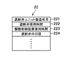
メモリ部22は、図5に示すように、遮断弁ユニット製造年月221、遮断弁使用時間222、駆動制御装置使用時間223、遮断弁の口径224、等の各種データを記憶する記憶領域を有している。
As shown in FIG. 5, the
遮断弁ユニット製造年月221は、遮断弁20A及び駆動制御装置20Bの少なくとも一方の製造年月を示す製造年月データが、製品出荷時等に設定される。なお、本実施形態では、遮断弁ユニット製造年月221が遮断弁20Aの製造年月データと駆動制御装置20Bの製造年月データの双方を有する構成としたことで、遮断弁20A及び駆動制御装置20Bの何れかのみを交換した場合に、該当する製造年月データのみを書き換えることを可能としている。
In the shut-off valve unit manufacturing date 221, manufacturing date data indicating the manufacturing date of at least one of the shut-off valve 20A and the
遮断弁使用時間222は、操作装置10から供給された電力を遮断弁20Aに通電した時間を示す通算時間データが設定される。駆動制御装置使用時間223は、操作装置10から供給された電力を駆動制御装置20Bに通電した時間を示す通算時間データが設定される。
As the shut-off valve usage time 222, total time data indicating the time during which the power supplied from the operating
遮断弁の口径224は、駆動制御装置20Bが制御対象としている遮断弁20Aの口径を示す口径データが設定される。なお、共通化された駆動制御装置20Bは、どのような口径の遮断弁20Aに装着されるか分からないため、遮断弁20A及び駆動制御装置20Bが一体に製造された遮断弁ユニット20にのみ、口径データが設定されている。このとき、遮断弁の口径224が請求項中の登録口径情報に相当している。また、遮断弁の口径224は、共通化された駆動制御装置20Bの場合には口径データが設定されていないため、本発明では、操作装置10に記憶している遮断弁の口径126を受信して記憶することになる。
The diameter 224 of the shutoff valve is set with bore diameter data indicating the diameter of the shutoff valve 20A that is the control target of the
よって、本実施形態ではメモリ部22が図1に請求項中の固有情報記憶手段22a及び登録口径情報記憶手段22bとして機能してる。なお、固有情報記憶手段22aについては、機能の追加、変更等による書き換えが不要であれば、ROM21bで実現させることもできる。
Therefore, in the present embodiment, the
通信部23は、上述した通信線3と電気的に接続されると共に、MPU21と電気的に接続されている。通信部23は、前記通信線3を介してMPU21から入力される各種電文を示す信号を操作装置10に送信すると共に、前記通信線3を介して操作装置10から受信した信号が示す電文をMPU21に出力する。
The
また、遮断弁ユニット20のCPU21aは、通信部23を介して操作装置10から遮断要求信号を受信すると、上述したように駆動部27を制御して遮断弁26を弁閉し、また、開放要求信号を受信すると、駆動部27を制御して遮断弁26を弁開する。このようにCPU21aは駆動制御手段として機能している。
When the
圧力センサ28は、MPU21に電気的に接続されており、配管5内の気体の空気圧の変化を感圧素子にて圧力信号に変換する機械式又は電子式のものが任意に用いられる。圧力センサ28は、遮断弁26の下流側(ガス供給側)における配管5内の圧力を感知して圧力信号をMPU21に出力する。
The
次に、上述した構成の駆動制御装置20BのCPU21aによる各種プログラムの実行によってCPU21aが機能する、図1に示す請求項中の各種手段の動作を説明する。
Next, operations of various means in the claims shown in FIG. 1 in which the
CPU21aの口径情報受信手段21a1は、通信部23を介して操作装置10から受信した各種情報の中から口径情報を受信する。CPU21aの固有情報抽出手段21a2は、その受信した口径情報をメモリ部22の遮断弁20Bの口径224に設定すると共に、メモリ部22に記憶している複数種類の口径情報の中から当該口径情報に対応した固有情報を抽出してRAM21cのパラメータ等に設定する。
The aperture information receiving means 21a1 of the
CPU21aの所定処理実行手段21a3は、固有情報に基づいて、予め定められた所定処理を行う所定処理プログラムを実行する。即ち、所定処理プログラムは、固有情報を遮断弁20Aの固有パラメータとして用いる処理プログラムであり、所定処理の一例としては、復帰漏洩確認処理、気密漏洩検査処理、等が挙げられる。
The predetermined process execution means 21a3 of the
CPU21aの登録口径情報送信手段21a4は、メモリ部22の遮断弁20Aの口径224に設定されている口径データを有する登録口径情報を作成し、通信部23を介して操作装置10に送信する。そして、CPU21aの識別情報送信手段21a5は、識別情報を作成し、通信部23を介して該識別情報を操作装置10に送信する。なお、本実施形態では、メモリ部22の遮断弁ユニット製造年月221に設定された製造年月データを有する識別情報を作成する場合について説明するが、本発明はこれに限定するものではなく、例えば駆動制御装置20Bの製造番号(シリアル番号)、登録番号、等の駆動制御装置20Bを識別可能な各種データを有する識別情報とすることができる。
The registered aperture information transmitting unit 21a4 of the
次に、上述した遮断システム1の操作装置10と遮断弁ユニット20の駆動制御装置20Bの本発明に係る動作(作用)の一例を、図7及び図8の図面を参照して以下に説明する。
Next, an example of the operation (action) according to the present invention of the
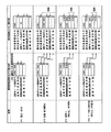
図7に示す製品出荷時の状態ST1において、駆動制御装置20Bのメモリ部22には、遮断弁ユニット製造年月221に「1009(上位)/1009(下位)」、遮断弁使用時間222に「0」、駆動制御装置使用時間223に「0」、口径224に「2」がそれぞれ設定されている。また、操作装置10のメモリ部12には、操作装置製造年月121に「1008」、操作装置使用時間122に「0」、遮断弁ユニット製造年月123に「0000(上位)/0000(下位)」、遮断弁使用時間124に「0」、駆動制御装置使用時間125に「0」、口径126に「0」がそれぞれ設定されている。なお、遮断弁ユニット製造年月123及び遮断弁ユニット製造年月221は、その上位が遮断弁20A、下位が駆動制御装置20Bに対応した内容になっている。
In the state ST1 at the time of product shipment shown in FIG. 7, the
設置、使用開始の状態ST2において、操作装置10と駆動制御装置20Bが結線されて、操作装置10から駆動制御装置20Bへの電力供給が開始されると、駆動制御装置20Bは操作装置10に遮断弁ユニット製造年月221を識別情報、遮断弁使用時間222及び駆動制御装置使用時間223を使用時間情報、口径224を口径情報(登録口径情報に相当)としてそれぞれ送信する。
In the installation and use start state ST2, when the
その結果、操作装置10のメモリ部12には、操作装置製造年月121及び操作装置使用時間122は更新されずに、遮断弁ユニット製造年月123に「1009/1009」、遮断弁使用時間124に「0」、駆動制御装置使用時間125に「0」、口径126に「2」がそれぞれ設定されて更新される。
As a result, in the
例えば1年使用した使用中の状態ST3において、操作装置10は駆動制御装置20Bへの通電中、例えば24時間毎に駆動制御装置20Bから前記使用時間情報を取得して、メモリ部12の遮断弁使用時間222及び駆動制御装置使用時間223の設定値を更新する。
For example, in the operating state ST3 used for one year, the operating
その結果、駆動制御装置20のメモリ部22の遮断弁使用時間222及び駆動制御装置使用時間223に書き込まれている「8760」が、操作装置10のメモリ部12の遮断弁使用時間124及び駆動制御装置使用時間125に設定されることで、操作装置10のメモリ部12が更新される。
As a result, “8760” written in the shut-off valve use time 222 and the drive control device use time 223 of the
例えば2年使用された操作装置10の表示操作時の状態ST4において、操作装置10は駆動制御装置20Bから前記使用時間情報を取得して、メモリ部12の遮断弁使用時間222及び駆動制御装置使用時間223の設定値を更新し、その内容を表示部17に表示する。
For example, in the state ST4 at the time of display operation of the
その結果、駆動制御装置20のメモリ部22の遮断弁使用時間222及び駆動制御装置使用時間223に書き込まれている「17520」が、操作装置10のメモリ部12の遮断弁使用時間124及び駆動制御装置使用時間125に設定されることで、操作装置10のメモリ部12が更新される。
As a result, “17520” written in the shut-off valve use time 222 and the drive control device use time 223 of the
例えば10年使用された駆動制御装置20Bが交換される状態ST5において、遮断弁ユニット20は新たな駆動制御装置20Bに交換されると、図8に示すように、駆動制御装置20Bのメモリ部22には、遮断弁ユニット製造年月221に「0000/2009」、遮断弁使用時間222に「0」、駆動制御装置使用時間223に「0」、口径224に「0」がそれぞれ設定されている。即ち、遮断弁ユニット製造年月221には駆動制御装置20Bの製造年月のみが設定され、口径224には初期値である「0」が設定されているため、駆動制御装置20Bは遮断弁20Aの口径に応じた各種処理を行うことができない状態となっている。
For example, in the state ST5 in which the
そして、操作装置10と新たな駆動制御装置20Bが結線されて、操作装置10から新たな駆動制御装置20Bへの電力供給が開始されると、駆動制御装置20Bは操作装置10に遮断弁ユニット製造年月221を識別情報、遮断弁使用時間222及び駆動制御装置使用時間223を使用時間情報、口径224を口径情報としてそれぞれ送信する。
When the
操作装置10は、今回受信した識別情報の遮断弁ユニット製造年月221とメモリ部12に記憶している識別情報の遮断弁ユニット製造年月123とを比較すると、一致しないことから、駆動制御装置20Bが交換されたものと判定する。そして、操作装置10は、メモリ部12の遮断弁ユニット製造年月221を「1009/1009」を「1009/2009」に上書きして更新し、駆動制御装置使用時間125に「0」を設定してクリアすると共に、メモリ部12の口径126に設定されている「2」を示す口径情報を作成して新たな駆動制御装置20Bに送信する。
When the
新たな駆動制御装置20Bは、受信した口径情報に基づいてメモリ部22の口径224を「0」から「2」に変更することで更新し、その口径情報に対応した固有情報をメモリ部22から抽出し、その固有情報を設定することで、その後は遮断弁2Aの口径に適した処理を行うことになる。
The new
以上説明した遮断システム1によれば、操作装置10が口径情報を駆動制御装置20Bに送信し、駆動制御装置20Bが受信した口径情報に対応した固有情報を複数の固有情報の中から抽出し、該固有情報に基づいて所定処理を実行するようにしたことから、操作装置10に口径情報を記憶させておくことで、駆動制御装置20Bを交換しても遮断弁20Aの口径情報を駆動制御装置20Bに自動で認識させることができるため、駆動制御装置20Bは遮断弁20Aの口径に適した各種処理を行うことができ、作業者が駆動制御装置20Bに口径を登録するという登録作業、通信により口径を登録するための装置等を不要とすることができる。従って、遮断弁20Aの口径を誤って設定することがなるため、遮断弁20Aの口径を検出する余計な口径検出機構を追加する必要がなくなり、遮断システム1のコストアップを防止できる。
According to the blocking system 1 described above, the operating
また、駆動制御装置20Bが登録口径情報を操作装置10に送信し、操作装置10がその受信した登録口径情報を口径情報としてメモリ部12に記憶するようにしたことから、遮断弁20Aに対応した登録口径情報を操作装置10に自動で記憶させることができるため、駆動制御装置20Bが口径情報を記憶していない共通の駆動制御装置20Bに交換されたときに、操作装置10から共通の駆動制御装置20Bに口径情報を送信して自動的に認識させることができる。よって、遮断弁20Aの口径の登録を要することなく、駆動制御装置20Bの共通化を図ることができるため、遮断システム1のさらなるコストダウンに貢献することができる。
Further, since the
さらに、駆動制御装置20Bがその識別情報を操作装置10に送信し、操作装置10が今回受信した識別情報と前回受信した識別情報とを比較して駆動制御装置20Bの交換を検出すると、その交換の検出に応じて記憶している口径情報を駆動制御装置20Bに送信するようにしたことから、駆動制御装置20Bの交換に応じて操作装置10に記憶している口径情報を駆動制御装置20Bに自動で記憶させることができるため、駆動制御装置20Bが口径情報を記憶していない共通の駆動制御装置20Bに交換されたときに、迅速に共通の駆動制御装置20Bに遮断弁20Aの口径を自動的に認識させることができる。
Furthermore, when the
このように上述した実施例は本発明の代表的な形態を示したに過ぎず、本発明は、実施形態に限定されるものではない。即ち、本発明の骨子を逸脱しない範囲で種々変形して実施することができる。 As described above, the above-described embodiments are merely representative forms of the present invention, and the present invention is not limited to the embodiments. That is, various modifications can be made without departing from the scope of the present invention.
1 遮断システム
10 操作装置
11a1 口径情報送信手段(操作装置のCPU)
11a2 登録口径情報受信手段(操作装置のCPU)
11a3 識別情報受信手段(操作装置のCPU)
11a4 交換検出手段(操作装置のCPU)
12 口径情報記憶手段(操作装置のメモリ部)
20 遮断弁ユニット
20A 遮断弁
20B 駆動制御装置
21a1 口径情報受信手段(駆動制御装置のCPU)
21a2 固有情報抽出手段(駆動制御装置のCPU)
21a3 所定処理実行手段(駆動制御装置のCPU)
21a4 登録口径情報送信手段(駆動制御装置のCPU)
21a5 識別情報送信手段(駆動制御装置のCPU)
22a 固有情報記憶手段(駆動制御装置のメモリ部)
22b 登録口径情報記憶手段(駆動制御装置のメモリ部)
DESCRIPTION OF SYMBOLS 1 Shut-
11a2 Registered aperture information receiving means (CPU of operating device)
11a3 Identification information receiving means (CPU of operating device)
11a4 Exchange detection means (CPU of operation device)
12 Aperture information storage means (memory part of operating device)
20 shutoff valve unit
21a2 Unique information extraction means (CPU of drive control device)
21a3 Predetermined processing execution means (CPU of drive control device)
21a4 registered aperture information transmission means (CPU of drive control device)
21a5 Identification information transmitting means (CPU of drive control device)
22a Unique information storage means (memory part of drive control device)
22b Registered aperture information storage means (memory portion of drive control device)
Claims (3)
前記操作装置が、前記駆動制御装置の駆動対象となる遮断弁の口径を示す口径情報を記憶する口径情報記憶手段と、前記口径情報記憶手段が記憶している口径情報を前記駆動制御装置に送信する口径情報送信手段と、を有し、
前記駆動制御装置が、前記複数種類の遮断弁の各々に対応した複数種類の固有情報を記憶する固有情報記憶手段と、前記操作装置の口径情報送信手段が送信した口径情報を受信する口径情報受信手段と、前記口径情報受信手段が受信した口径情報に対応した前記固有情報を、前記複数種類の固有情報の中から抽出する固有情報抽出手段と、前記固有情報抽出手段が抽出した固有情報に基づいて、予め定められた所定処理を実行する所定処理実行手段と、を有することを特徴とする遮断システム。 In a shut-off system having a drive control device that controls driving of a plurality of types of shut-off valves having different diameters, and an operation device that supplies power to the drive control device and communicates with the drive control device,
The operating device transmits to the drive controller the aperture information storage means for storing aperture information indicating the aperture of the shutoff valve to be driven by the drive control device, and the aperture information stored in the aperture information storage means. Aperture information transmission means for
The drive control device receives unique information storage means for storing plural kinds of unique information corresponding to each of the plural kinds of shut-off valves, and caliber information reception for receiving caliber information transmitted by the caliber information transmitting means of the operating device. Based on the unique information extracted by the unique information extracting means, the unique information extracting means for extracting the unique information corresponding to the aperture information received by the aperture information receiving means from the plurality of types of unique information And a predetermined process executing means for executing predetermined predetermined processes.
前記操作装置が、前記駆動制御装置の登録口径情報送信手段が送信した登録口径情報を受信する登録口径情報受信手段を有し、
前記口径情報記憶手段が、前記登録口径情報受信手段によって受信した登録口径情報を前記口径情報として記憶する手段であることを特徴とする請求項1に記載の遮断システム。 The drive control device, the shut-off valve detachably attached to the drive control device, registered aperture information storage means for storing registered aperture information indicating the aperture registered corresponding to the mounted shut-off valve, and Registration aperture information transmitting means for transmitting the registered aperture information stored in the registered aperture information storage means to the operating device, and
The operating device has a registered aperture information receiving means for receiving the registered aperture information transmitted by the registered aperture information transmitting means of the drive control device;
The blocking system according to claim 1, wherein the aperture information storage means is means for storing the registered aperture information received by the registered aperture information receiving means as the aperture information.
前記操作装置が、前記識別情報を前記駆動制御装置から受信する識別情報受信手段と、前記受信した識別情報と前回受信した識別情報との比較結果に基づいて前記駆動制御装置の交換を検出する交換検出手段と、を有し、
前記操作装置の口径情報送信手段が、前記交換検出手段による交換の検出に応じて、前記口径情報を前記駆動制御装置に送信する手段であることを特徴とする請求項1又は2に記載の遮断システム。 The drive control device has identification information transmitting means for transmitting identification information for identifying the drive control device to the operation device;
The operation device detects an exchange of the drive control device based on a comparison result between the identification information receiving means for receiving the identification information from the drive control device and the received identification information and the previously received identification information. Detecting means,
3. The blocking according to claim 1, wherein the aperture information transmitting means of the operating device is means for transmitting the aperture information to the drive control device in response to detection of replacement by the replacement detection means. system.
Priority Applications (1)
| Application Number | Priority Date | Filing Date | Title |
|---|---|---|---|
| JP2008210310A JP5156535B2 (en) | 2008-08-19 | 2008-08-19 | Shut-off system |
Applications Claiming Priority (1)
| Application Number | Priority Date | Filing Date | Title |
|---|---|---|---|
| JP2008210310A JP5156535B2 (en) | 2008-08-19 | 2008-08-19 | Shut-off system |
Publications (2)
| Publication Number | Publication Date |
|---|---|
| JP2010048264A true JP2010048264A (en) | 2010-03-04 |
| JP5156535B2 JP5156535B2 (en) | 2013-03-06 |
Family
ID=42065520
Family Applications (1)
| Application Number | Title | Priority Date | Filing Date |
|---|---|---|---|
| JP2008210310A Active JP5156535B2 (en) | 2008-08-19 | 2008-08-19 | Shut-off system |
Country Status (1)
| Country | Link |
|---|---|
| JP (1) | JP5156535B2 (en) |
Citations (12)
| Publication number | Priority date | Publication date | Assignee | Title |
|---|---|---|---|---|
| JPH07248070A (en) * | 1994-03-11 | 1995-09-26 | Yazaki Corp | Gas emergency trip valve |
| JP3045032U (en) * | 1997-07-02 | 1998-01-23 | 株式会社三菱総合研究所 | Plant valve opening / closing operation support device using non-contact type IC |
| JP2003035782A (en) * | 2001-07-23 | 2003-02-07 | Fuji Tecom Inc | Position information editing control method for underground facility and record medium recording program for the same |
| JP2003035380A (en) * | 2001-05-14 | 2003-02-07 | Kubota Corp | Valve operating machine with opening detecting function |
| JP2003139268A (en) * | 2001-10-31 | 2003-05-14 | Kubota Corp | Valve with information storage function and valve operation machine thereof |
| JP2003139271A (en) * | 2001-10-31 | 2003-05-14 | Kubota Corp | Pipe passage network management method |
| JP2003343761A (en) * | 2002-05-30 | 2003-12-03 | Idemitsu Kosan Co Ltd | Valve operation support system |
| JP2005135227A (en) * | 2003-10-31 | 2005-05-26 | Maezawa Ind Inc | Valve information management device |
| JP2005291321A (en) * | 2004-03-31 | 2005-10-20 | Kawaden:Kk | Electric actuator and electric valve using electric actuator |
| JP2007233497A (en) * | 2006-02-28 | 2007-09-13 | Hitachi Ltd | Valve management system using rfid tag |
| JP2007270957A (en) * | 2006-03-31 | 2007-10-18 | Yazaki Corp | Gas cutoff valve |
| JP2008128704A (en) * | 2006-11-17 | 2008-06-05 | Matsushita Electric Ind Co Ltd | Gas apparatus monitoring device |
-
2008
- 2008-08-19 JP JP2008210310A patent/JP5156535B2/en active Active
Patent Citations (12)
| Publication number | Priority date | Publication date | Assignee | Title |
|---|---|---|---|---|
| JPH07248070A (en) * | 1994-03-11 | 1995-09-26 | Yazaki Corp | Gas emergency trip valve |
| JP3045032U (en) * | 1997-07-02 | 1998-01-23 | 株式会社三菱総合研究所 | Plant valve opening / closing operation support device using non-contact type IC |
| JP2003035380A (en) * | 2001-05-14 | 2003-02-07 | Kubota Corp | Valve operating machine with opening detecting function |
| JP2003035782A (en) * | 2001-07-23 | 2003-02-07 | Fuji Tecom Inc | Position information editing control method for underground facility and record medium recording program for the same |
| JP2003139268A (en) * | 2001-10-31 | 2003-05-14 | Kubota Corp | Valve with information storage function and valve operation machine thereof |
| JP2003139271A (en) * | 2001-10-31 | 2003-05-14 | Kubota Corp | Pipe passage network management method |
| JP2003343761A (en) * | 2002-05-30 | 2003-12-03 | Idemitsu Kosan Co Ltd | Valve operation support system |
| JP2005135227A (en) * | 2003-10-31 | 2005-05-26 | Maezawa Ind Inc | Valve information management device |
| JP2005291321A (en) * | 2004-03-31 | 2005-10-20 | Kawaden:Kk | Electric actuator and electric valve using electric actuator |
| JP2007233497A (en) * | 2006-02-28 | 2007-09-13 | Hitachi Ltd | Valve management system using rfid tag |
| JP2007270957A (en) * | 2006-03-31 | 2007-10-18 | Yazaki Corp | Gas cutoff valve |
| JP2008128704A (en) * | 2006-11-17 | 2008-06-05 | Matsushita Electric Ind Co Ltd | Gas apparatus monitoring device |
Also Published As
| Publication number | Publication date |
|---|---|
| JP5156535B2 (en) | 2013-03-06 |
Similar Documents
| Publication | Publication Date | Title |
|---|---|---|
| US20170300027A1 (en) | Information processing system, information processing method, information processing apparatus, terminal apparatus, water supply apparatus, and control method for water supply apparatus | |
| US20140216071A1 (en) | Controlling refrigeration appliances with a portable electronic device | |
| US20170131705A1 (en) | Field device, field device system, and diagnostic method | |
| US20080312877A1 (en) | Method and Device for Functional Checking of a Field Device Before the Comissioning Thereof | |
| US10590008B1 (en) | Liquid treatment control system | |
| WO2014162811A1 (en) | Plant facilities management system and plant facilities management system control method | |
| US10829388B1 (en) | Valve control apparatus | |
| US8680980B2 (en) | Blank tire pressure monitoring device and its setup method | |
| US7940164B2 (en) | Method for programming new sensor in a motor vehicle monitoring system | |
| CN203670999U (en) | Valve comprising valve position indicator | |
| US10626513B1 (en) | Water electrolysis hydrogen production plant with a pumpless water supply system and process flow method | |
| EP2495113A1 (en) | Blank tire pressure monitoring device and its setup method | |
| JP5156535B2 (en) | Shut-off system | |
| JP5150408B2 (en) | Shut-off system | |
| JP2008143418A (en) | Data rewriting state display control device | |
| JP5739084B2 (en) | Gas leak detection device | |
| US11203532B1 (en) | Piston valve with annular passages | |
| JP2006132870A (en) | Maintenance system for air conditioner | |
| CN114251812A (en) | Parameter setting method and device of air conditioner and air conditioner | |
| JP2006242652A (en) | Electronic gas meter | |
| US20140172178A1 (en) | Control method of an in-house device using a control kit and control method for a water purifier using a control kit | |
| US20080167745A1 (en) | Method And Device For The Diagnosis Of Technical Devices Disposed Within An Industrial Installation | |
| US20200306672A1 (en) | Leak detection assembly for use with a filter assembly for a refrigerator appliance | |
| CN112395206A (en) | Configuration software error correction method and system | |
| JP2007240411A (en) | Gas meter |
Legal Events
| Date | Code | Title | Description |
|---|---|---|---|
| A621 | Written request for application examination |
Free format text: JAPANESE INTERMEDIATE CODE: A621 Effective date: 20101227 |
|
| A977 | Report on retrieval |
Free format text: JAPANESE INTERMEDIATE CODE: A971007 Effective date: 20120525 |
|
| A131 | Notification of reasons for refusal |
Free format text: JAPANESE INTERMEDIATE CODE: A131 Effective date: 20120612 |
|
| A521 | Request for written amendment filed |
Free format text: JAPANESE INTERMEDIATE CODE: A523 Effective date: 20120730 |
|
| A711 | Notification of change in applicant |
Free format text: JAPANESE INTERMEDIATE CODE: A712 Effective date: 20120926 |
|
| RD03 | Notification of appointment of power of attorney |
Free format text: JAPANESE INTERMEDIATE CODE: A7423 Effective date: 20120927 |
|
| RD04 | Notification of resignation of power of attorney |
Free format text: JAPANESE INTERMEDIATE CODE: A7424 Effective date: 20121005 |
|
| TRDD | Decision of grant or rejection written | ||
| A01 | Written decision to grant a patent or to grant a registration (utility model) |
Free format text: JAPANESE INTERMEDIATE CODE: A01 Effective date: 20121120 |
|
| A61 | First payment of annual fees (during grant procedure) |
Free format text: JAPANESE INTERMEDIATE CODE: A61 Effective date: 20121210 |
|
| FPAY | Renewal fee payment (event date is renewal date of database) |
Free format text: PAYMENT UNTIL: 20151214 Year of fee payment: 3 |
|
| R150 | Certificate of patent or registration of utility model |
Free format text: JAPANESE INTERMEDIATE CODE: R150 Ref document number: 5156535 Country of ref document: JP Free format text: JAPANESE INTERMEDIATE CODE: R150 |
|
| R250 | Receipt of annual fees |
Free format text: JAPANESE INTERMEDIATE CODE: R250 |
|
| R250 | Receipt of annual fees |
Free format text: JAPANESE INTERMEDIATE CODE: R250 |
|
| R250 | Receipt of annual fees |
Free format text: JAPANESE INTERMEDIATE CODE: R250 |
|
| R250 | Receipt of annual fees |
Free format text: JAPANESE INTERMEDIATE CODE: R250 |
|
| R250 | Receipt of annual fees |
Free format text: JAPANESE INTERMEDIATE CODE: R250 |
|
| R250 | Receipt of annual fees |
Free format text: JAPANESE INTERMEDIATE CODE: R250 |
|
| R250 | Receipt of annual fees |
Free format text: JAPANESE INTERMEDIATE CODE: R250 |
|
| R250 | Receipt of annual fees |
Free format text: JAPANESE INTERMEDIATE CODE: R250 |
|
| S531 | Written request for registration of change of domicile |
Free format text: JAPANESE INTERMEDIATE CODE: R313531 |
|
| R350 | Written notification of registration of transfer |
Free format text: JAPANESE INTERMEDIATE CODE: R350 |
|
| R250 | Receipt of annual fees |
Free format text: JAPANESE INTERMEDIATE CODE: R250 |