JP2010046091A - Apparatus for mounting bird-repelling tool - Google Patents
Apparatus for mounting bird-repelling tool Download PDFInfo
- Publication number
- JP2010046091A JP2010046091A JP2009262160A JP2009262160A JP2010046091A JP 2010046091 A JP2010046091 A JP 2010046091A JP 2009262160 A JP2009262160 A JP 2009262160A JP 2009262160 A JP2009262160 A JP 2009262160A JP 2010046091 A JP2010046091 A JP 2010046091A
- Authority
- JP
- Japan
- Prior art keywords
- mounting
- electric shock
- bird
- chip
- lever member
- Prior art date
- Legal status (The legal status is an assumption and is not a legal conclusion. Google has not performed a legal analysis and makes no representation as to the accuracy of the status listed.)
- Granted
Links
Images


Abstract
Description
本発明は、ハトやカラスを始めとする鳥類による糞害や営巣を防止するための防鳥具の取付装置に関する。 The present invention relates to an attachment device for a bird protection tool for preventing dung damage and nesting by birds such as pigeons and crows.
近年、市街地での鳥類による被害が多発しており、特に高架橋下、看板や広告塔、電柱、建物のベランダや屋上、ビルの窓枠部、屋根付き駐車場、工場や倉庫、神社や仏閣等では、飛来したハトやカラス等が巣作りしたり、糞を撒き散らして周辺を汚すことが大きな社会問題になっている。 In recent years, there has been a lot of damage caused by birds in urban areas, especially under viaducts, signs and advertising towers, utility poles, building verandas and rooftops, building window frames, covered parking lots, factories and warehouses, shrines and Buddhist temples, etc. Then, it is a big social problem that pigeons and crows, etc. that have come to nest, or sprinkle the shit to pollute the surroundings.
そこで、防鳥対策として、従来より、鳥が留まり易い部位や営巣し易い部位にピンを剣山状に設置する方法(特許文献1〜4)、建物やベランダ等の開口部に侵入防止用のネットやワイヤーを張り巡らす方法(特許文献5〜8)、鳥が留まり易い部位に沿って電撃用の通電線を配線する方法等が一般的に採用されている。
Therefore, as a countermeasure against birds, conventionally, a method of installing a pin in a sword mountain shape on a part where birds tend to stay or nest (
しかしながら、前記従来の防鳥対策では、防鳥手段毎に専用の取付装置を用いることになるが、剣山状のピンの設置、ネットやワイヤーの張設、更には電撃用通電線の配線等の作業に多大な手間及び時間を要して施工能率が悪く、またそれぞれの施工操作を習熟するのに時間と労力を要するという問題があった。 However, in the conventional bird-proof measures, a dedicated mounting device is used for each bird-proof means. However, such as installation of a sword mountain-shaped pin, tension of a net or wire, and wiring of a current carrying wire for electric shock, etc. There is a problem that the work efficiency is poor because it takes a lot of labor and time for the work, and it takes time and labor to master each construction operation.
本発明は、上述の事情に鑑みて、特に電撃用通電線を利用する防鳥具取付装置として、配線施工操作が容易で、施工に要する時間及び労力を低減でき、熟練を要さずに高い施工能率が得られるものを提供することを目的としている。 In view of the above-described circumstances, the present invention is particularly easy as a bird's armor mounting device that uses an electric wire for electric shock. Wiring construction operation is easy, time and labor required for construction can be reduced, and high skill is not required. The purpose is to provide a construction efficiency.
上記目的を達成するために、本発明の請求項1に係る防鳥具取付装置は、図面の参照符号を付して示せば、取付基体Mに接着又はねじ止めする略板状の取付チップ1に、電撃配線用の碍子部材2を保持させる碍子保持部が一体形成されてなり、該碍子保持部は、前記碍子部材2の両側面部に対して摺動可能に凹凸係合する両側一対のスライド嵌合部17,17にて構成されるものとしている。
In order to achieve the above-mentioned object, a bird guard mounting device according to
請求項2の発明は、上記請求項1の防鳥具取付装置において、前記碍子部材2が、平面視で長細い形状を備え、その長手方向とこれに直交する方向との二方向に沿う各複数本の電撃線3に対応した電撃線挿通孔21a〜21cを備える構成としている。
According to a second aspect of the present invention, in the bird's armor mounting apparatus according to the first aspect, each of the
請求項3の発明は、上記請求項1又は2の防鳥具取付装置において、前記取付チップ1に、表裏方向に貫通する複数の貫通穴14・・・(孔11,ねじ止め穴15)が設けられてなる構成としている。
A third aspect of the present invention is the bird's-eye protector mounting apparatus according to the first or second aspect, wherein the
請求項1の発明に係る防鳥具取付装置によれば、取付チップを建物等の取付基体に対して接着又はねじ止めすることで簡単確実に固定できる共に、碍子部材をその取付チップにスライド操作することによって簡単に着脱することができる。それがために、電撃用通電線の配線施工操作が容易となり、施工に要する時間及び労力を低減できる共に、熟練を要さず施工することができるため、高い施工能率を発揮することができる。 According to the bird protection device mounting apparatus of the first aspect of the present invention, the mounting tip can be easily and securely fixed by bonding or screwing to a mounting base such as a building, and the lever member is slid to the mounting tip. Can be easily attached and detached. Therefore, the wiring construction operation of the electric wire for electric shock can be facilitated, the time and labor required for construction can be reduced, and the construction can be performed without requiring skill, so that high construction efficiency can be exhibited.
請求項2の発明によれば、平面視で長細い形状の碍子部材に、その長手方向とこれに直交する方向に沿う各複数本の電撃線に対応する電撃線挿通孔を有するから、取付チップに保持させる当該碍子部材の向きを縦横に選択することにより、周辺状況に応じて電撃配線幅を広狭いずれかに設定できる。
According to the invention of
請求項3の発明によれば、取付チップが表裏方向に貫通する複数の貫通穴を備えるから、取付基体に対して当該取付チップを接着剤によって固着する際、接着剤が貫通穴に入り込んで固化し、そのアンカー作用で当該取付チップの固着強度が格段に増大する。
According to the invention of
以下、本発明に係る防鳥具取付装置の実施形態について、図面を参照して具体的に説明する。 DESCRIPTION OF EMBODIMENTS Hereinafter, embodiments of a bird's arm attachment device according to the present invention will be specifically described with reference to the drawings.
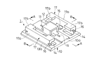
図1及び図2(A)(B)は、防鳥具取付装置の取付チップ1を示す。この取付チップ1は、全体が硬質合成樹脂成形物からなり、平面視正方形の板状ベース部10の上面中央に、フック係着部を構成する下向きコ字枠状の差込みゲート12が突設され、該板状ベース部10が差込みゲート12の前後両側で膨出部10a,10aによって厚肉化すると共に、この前後の膨出部10a,10aに、一対の孔11,11が上下方向に貫設され、また該板状ベース部10の上面左右両側に、碍子保持部を構成する一対のスライド嵌合部17,17が立ち上げ形成されている。
FIG.1 and FIG.2 (A) (B) shows the attachment chip |
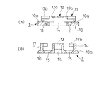
しかして、孔11は、板状ベース部10の上面側では前後方向に沿う長孔として開口すると共に、同下面側では丸孔として開口しており、図2(A)に示すように、差込みゲート12側の内側面部が垂直で、反対側の内側面部が傾斜した形になっている。また、差込みゲート12の出口側となる後端側の上縁部12aが後方へ突出している。
Thus, the hole 11 opens as a long hole along the front-rear direction on the upper surface side of the plate-
一方、碍子保持部の各スライド嵌合部17は、前後方向に沿う垂直壁部17aの前後両側部に、上端から内向きに突出する係合片17b,17bを一体形成したものであり、その垂直壁部17aには前後両端面から斜め上向きに凹入するネット仮止め用溝16,16が設けられている。なお、本実施形態におけるネット仮止め用溝16,16は、設けてもよいし設けなくてもよい。
On the other hand, each slide fitting
さらに、板状ベース部10には、各係合片17bの下方位置と差込みゲート12の下方位置との計5箇所に、前後方向に長い略矩形の貫通穴14・・・が設けられると共に、図2(B)に示すように、差込みゲート12と左右の垂直壁部17a,17aとの間に、円形で上方へ拡径したねじ止め穴15,15が開設されている。そして、板状ベース部10の左右側縁は、上半部13aを傾斜面として厚みを約半分に減じている。
Further, the plate-
なお、取付チップ1の通常のサイズは、板状ベース部10の一辺が20〜50mm程度、該板状ベース部10の膨出部10a以外の厚みが1〜3mm程度、差込みゲート12及びスライド嵌合部17の板状ベース部10下面からの高さが5〜10mm程度、にそれぞれ設定される。
The normal size of the
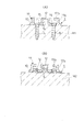
このような取付チップ1を防鳥部位の取付基体に止着するには、図3(A)に示すように木製の取付基体M1に対し、ねじ止め穴15,15を利用して木ねじNによってねじ止めするか、もしくは図3(B)に示すように各種材質の取付基体M2に対し、例えばエポキシ系接着剤の如き主剤と硬化剤とからなる二液性ボンド等の接着剤Sによって接着固定すればよい。後者の接着固定では、接着剤Sが貫通穴14・・・,孔11,11及びねじ止め穴15,15に入り込んで固化することでアンカー作用を発揮するから、当該取付チップ1は固着強度が格段に増大して剥落しにくくなる。
In order to fix the
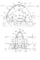
以上のように構成される防鳥具取付装置の取付チップ1を防鳥用電撃配線に適用する場合、図4(A)〜(C)に示すような碍子部材2を用いる。この碍子部材2は、側面視が略60°短軸に沿って半割した形で、底面外形が略25°楕円をなし、底面側に開放した硬質合成樹脂中空成形物からなり、左右両側面で大小の二等辺三角形の各頂点をなすように配置した外側及び内側各3つの電撃線挿通孔21a,21bが左右方向に貫通し、前後方向にも上下2つの電撃線挿通孔21cが貫通している。そして、この碍子部材2には、図5の如く取付チップ1に嵌着させるために、左右両側面の下部に前後方向に沿うスライドガイド溝22,22が形成されると共に、前端下部に中空内部20へ連通して下方に開く矩形開口部23が設けられ、また後部の下方突出によって前方に臨むストッパー段部24が形成されている。
When applying the
すなわち、各碍子部材2は、図6(A)(B)に示すように、電撃配線を施す取付基体Mの要所に予め止着した取付チップ1に対し、そのスライド嵌合部17,17の間に下部が入り込むように前方側からスライド嵌合操作する。これにより、取付チップ1のスライド嵌合部17,17の係合片17b,17bが碍子部材2の両スライドガイド溝22,22に嵌入し、碍子部材2のストッパー段部24が該取付チップ1の板状ベース部10の端縁に当接することで、碍子部材2はより以上の前方移動が不能な位置決め嵌着状態となる。なお、取付チップ1の中央部で突出する差込みゲート12は、碍子部材5に干渉せずに矩形開口部23から図6(B)の如く中空内部20へ入り込むので、スライド嵌合操作の支障にならない。
That is, as shown in FIGS. 6 (A) and 6 (B), each
このような碍子部材2と取付チップ1を用いた電撃配線は、碍子部材2・・・に通した裸導線である電撃線3に通電し、これに留まろうとした鳥に軽い電気ショックを与えて嫌忌効果を得るものである。しかして、図5及び図6では碍子部材2の左右両側面における小さい二等辺三角形の各頂点をなす内側3つの電撃線挿通孔21bに電撃線3を挿通した状態を例示しているが、この碍子部材2によれば3通りの配線パターンを選択できる。すなわち、ハトやカラス等の大型鳥類を対象とする場合は大きい二等辺三角形の各頂点をなす外側3つの各電撃線挿通孔21aを通した相互間隔の大きい3本配線パターンとし、小型鳥類を対象とする場合は図示した相互間隔の小さい3本配線パターンとすればよい。また周辺状況等から三角形配置の3本配線パターンとする空間的余裕がない場合は、図6の仮想線で示すように、前後方向に沿う上下2つの電撃線挿通孔21cを利用した上下2本の配線パターンを採用できる。なお、電撃線3は、鳥を感電させる上で少なくとも1本をアース線として複数本を必要とする。また、図6の仮想線で示す上下2本の配線パターンでは、三角形配置の3本配線パターンとは碍子部材2の向きが90度異なるから、これに対応して予め取付基体Mに止着する取付チップ1の向きも変わることになる。
Such an electric shock wiring using the
以上説明した本実施形態に係る防鳥具取付装置によれば、建物等の取付基体Mに取付チップ1を接着又はねじ止めすることで簡単確実に固定できる共に、碍子部材2をその取付チップ1にスライド操作することによって簡単に着脱することができる。それがために、電撃用通電線の配線施工操作が容易となり、施工に要する時間及び労力を低減できる共に、熟練を要さず施工することができるため、高い施工能率を発揮することができる。
According to the bird protection device mounting apparatus according to the present embodiment described above, the mounting
なお、本実施形態において例示した取付チップにおける取付チップの板状ベース部における貫通穴の数、穴形状、形成位置等、細部構成について実施例以外に種々設計変更可能である。また、電撃配線用の碍子部材と取付チップとのスライド嵌合部は、その凹凸関係が実施形態とは逆であってもよい。さらに、碍子部材における全体形状、電撃線挿通孔の数と配置についても、例示以外に種々設定可能である。 In addition to the examples, various design changes can be made to the detailed configuration such as the number of through holes, the hole shape, and the formation position in the plate-like base portion of the mounting chip in the mounting chip exemplified in the present embodiment. Moreover, as for the slide fitting part of the insulator member for electric shock wiring, and the attachment chip | tip, the uneven | corrugated relationship may be reverse to embodiment. Further, the overall shape of the lever member and the number and arrangement of the electric wire insertion holes can be variously set in addition to the examples.
1 取付チップ
10 板状ベース部
11 孔(貫通穴)
14 貫通穴
15 ねじ止め穴(貫通穴)
17 スライド嵌合部(碍子保持部)
2 碍子部材
21a 電撃線挿通孔
21b 電撃線挿通孔
21c 電撃線挿通孔
3 電撃線
M 取付基体
M1,M2 取付基体
S 接着剤
1 Mounting
14 Through
17 Slide fitting part (insulator holding part)
2
Claims (3)
該碍子保持部は、前記碍子部材の両側面部に対して摺動可能に凹凸係合する両側一対のスライド嵌合部にて構成されてなる防鳥具取付装置。 A lever holding part for holding a lever member for electric shock wiring is integrally formed on a substantially plate-shaped mounting chip that is bonded or screwed to the mounting base.
The bird holding device includes a pair of slide fitting portions that are slidably engaged with both side surfaces of the lever member so as to be slidable.
Priority Applications (1)
| Application Number | Priority Date | Filing Date | Title |
|---|---|---|---|
| JP2009262160A JP5042295B2 (en) | 2009-11-17 | 2009-11-17 | Bird protection equipment |
Applications Claiming Priority (1)
| Application Number | Priority Date | Filing Date | Title |
|---|---|---|---|
| JP2009262160A JP5042295B2 (en) | 2009-11-17 | 2009-11-17 | Bird protection equipment |
Related Parent Applications (1)
| Application Number | Title | Priority Date | Filing Date |
|---|---|---|---|
| JP2006247750A Division JP4474394B2 (en) | 2006-09-13 | 2006-09-13 | Bird protection equipment |
Publications (2)
| Publication Number | Publication Date |
|---|---|
| JP2010046091A true JP2010046091A (en) | 2010-03-04 |
| JP5042295B2 JP5042295B2 (en) | 2012-10-03 |
Family
ID=42063726
Family Applications (1)
| Application Number | Title | Priority Date | Filing Date |
|---|---|---|---|
| JP2009262160A Active JP5042295B2 (en) | 2009-11-17 | 2009-11-17 | Bird protection equipment |
Country Status (1)
| Country | Link |
|---|---|
| JP (1) | JP5042295B2 (en) |
Cited By (12)
| Publication number | Priority date | Publication date | Assignee | Title |
|---|---|---|---|---|
| US8344665B2 (en) | 2008-03-27 | 2013-01-01 | Orion Energy Systems, Inc. | System and method for controlling lighting |
| US8476565B2 (en) | 2007-06-29 | 2013-07-02 | Orion Energy Systems, Inc. | Outdoor lighting fixtures control systems and methods |
| US8586902B2 (en) | 2007-06-29 | 2013-11-19 | Orion Energy Systems, Inc. | Outdoor lighting fixture and camera systems |
| US8729446B2 (en) | 2007-06-29 | 2014-05-20 | Orion Energy Systems, Inc. | Outdoor lighting fixtures for controlling traffic lights |
| CN105265425A (en) * | 2015-11-28 | 2016-01-27 | 国网江西省电力公司赣西供电分公司 | Bird driving device for pole |
| US9521726B2 (en) | 2007-05-03 | 2016-12-13 | Orion Energy Systems, Inc. | Lighting systems and methods for displacing energy consumption using natural lighting fixtures |
| CN107079905A (en) * | 2017-04-17 | 2017-08-22 | 朱德仲 | A kind of crops protection moves adjusting means with laser bird dispeller |
| US9951933B2 (en) | 2009-09-04 | 2018-04-24 | Orion Energy Systems, Inc. | Outdoor lighting fixtures and related systems and methods |
| US10098213B2 (en) | 2007-06-29 | 2018-10-09 | Orion Energy Systems, Inc. | Lighting fixture control systems and methods |
| CN108719266A (en) * | 2018-07-17 | 2018-11-02 | 国网江西省电力有限公司电力科学研究院 | A kind of long-acting scarer of self-energizing |
| US10334704B2 (en) | 2008-03-27 | 2019-06-25 | Orion Energy Systems, Inc. | System and method for reducing peak and off-peak electricity demand by monitoring, controlling and metering lighting in a facility |
| KR20220139673A (en) * | 2021-04-08 | 2022-10-17 | (주)하이쏠라에너지 | Electric shock type birds repeller |
Families Citing this family (1)
| Publication number | Priority date | Publication date | Assignee | Title |
|---|---|---|---|---|
| JP4295521B2 (en) | 2003-02-13 | 2009-07-15 | 株式会社日本触媒 | Catalyst for producing acrylic acid and method for producing acrylic acid |
-
2009
- 2009-11-17 JP JP2009262160A patent/JP5042295B2/en active Active
Cited By (21)
| Publication number | Priority date | Publication date | Assignee | Title |
|---|---|---|---|---|
| US9521726B2 (en) | 2007-05-03 | 2016-12-13 | Orion Energy Systems, Inc. | Lighting systems and methods for displacing energy consumption using natural lighting fixtures |
| US10187557B2 (en) | 2007-06-29 | 2019-01-22 | Orion Energy Systems, Inc. | Outdoor lighting fixture and camera systems |
| US10206265B2 (en) | 2007-06-29 | 2019-02-12 | Orion Energy Systems, Inc. | Outdoor lighting fixtures control systems and methods |
| US8729446B2 (en) | 2007-06-29 | 2014-05-20 | Orion Energy Systems, Inc. | Outdoor lighting fixtures for controlling traffic lights |
| US11026302B2 (en) | 2007-06-29 | 2021-06-01 | Orion Energy Systems, Inc. | Outdoor lighting fixtures control systems and methods |
| US8476565B2 (en) | 2007-06-29 | 2013-07-02 | Orion Energy Systems, Inc. | Outdoor lighting fixtures control systems and methods |
| US8586902B2 (en) | 2007-06-29 | 2013-11-19 | Orion Energy Systems, Inc. | Outdoor lighting fixture and camera systems |
| US10694594B2 (en) | 2007-06-29 | 2020-06-23 | Orion Energy Systems, Inc. | Lighting fixture control systems and methods |
| US11202355B2 (en) | 2007-06-29 | 2021-12-14 | Orion Energy Systems, Inc. | Outdoor lighting fixture and camera systems |
| US10694605B2 (en) | 2007-06-29 | 2020-06-23 | Orion Energy Systems, Inc. | Outdoor lighting fixtures control systems and methods |
| US11432390B2 (en) | 2007-06-29 | 2022-08-30 | Orion Energy Systems, Inc. | Outdoor lighting fixtures control systems and methods |
| US10098213B2 (en) | 2007-06-29 | 2018-10-09 | Orion Energy Systems, Inc. | Lighting fixture control systems and methods |
| US10334704B2 (en) | 2008-03-27 | 2019-06-25 | Orion Energy Systems, Inc. | System and method for reducing peak and off-peak electricity demand by monitoring, controlling and metering lighting in a facility |
| US8344665B2 (en) | 2008-03-27 | 2013-01-01 | Orion Energy Systems, Inc. | System and method for controlling lighting |
| US9951933B2 (en) | 2009-09-04 | 2018-04-24 | Orion Energy Systems, Inc. | Outdoor lighting fixtures and related systems and methods |
| CN105265425A (en) * | 2015-11-28 | 2016-01-27 | 国网江西省电力公司赣西供电分公司 | Bird driving device for pole |
| CN107079905A (en) * | 2017-04-17 | 2017-08-22 | 朱德仲 | A kind of crops protection moves adjusting means with laser bird dispeller |
| CN108719266B (en) * | 2018-07-17 | 2024-02-06 | 国网江西省电力有限公司电力科学研究院 | Self-energy-taking long-acting bird repellent device |
| CN108719266A (en) * | 2018-07-17 | 2018-11-02 | 国网江西省电力有限公司电力科学研究院 | A kind of long-acting scarer of self-energizing |
| KR20220139673A (en) * | 2021-04-08 | 2022-10-17 | (주)하이쏠라에너지 | Electric shock type birds repeller |
| KR102589342B1 (en) * | 2021-04-08 | 2023-10-16 | (주)하이쏠라에너지 | Electric shock type birds repeller |
Also Published As
| Publication number | Publication date |
|---|---|
| JP5042295B2 (en) | 2012-10-03 |
Similar Documents
| Publication | Publication Date | Title |
|---|---|---|
| JP5042295B2 (en) | Bird protection equipment | |
| KR101815510B1 (en) | Structure for installing deck | |
| US8523506B2 (en) | Cable staple | |
| ATE527734T1 (en) | FASTENING ELEMENT FOR ATTACHING A CAN TO A WIRE TRUNK | |
| KR20170000783U (en) | Device for birds-repellence and prevention | |
| JP4474394B2 (en) | Bird protection equipment | |
| KR102259672B1 (en) | Frame for fixing wire netting | |
| CN204154621U (en) | Metal material atmospheric corrosion exposes frame | |
| JP5938329B2 (en) | Fixing method of furniture in outdoor part of building | |
| JP2007178568A (en) | Optical indoor cable used for both of corner/floor | |
| KR101810954B1 (en) | Clip for fixing deck | |
| US7537191B2 (en) | Mounting device | |
| KR101580095B1 (en) | Post for wire netting fence | |
| JP6305618B1 (en) | Electric fence fitting | |
| JP2013247865A (en) | Bird-preventing net-attaching device | |
| JP2013247864A (en) | Electric shock wire connection tool for bird come-flying prevention device | |
| JP3176168U (en) | Birds flying prevention device | |
| CN214786534U (en) | Assembled view wooden fence | |
| CN202519564U (en) | Wooden trestle face plate | |
| JP2011103806A (en) | Bird-repelling device | |
| JP2006112041A (en) | Lath net and construction method for wall body using it | |
| JP2014173369A (en) | Sheet fixing method and sheet fixed part | |
| JP5789169B2 (en) | Joint structure and method for forming joint structure | |
| JP3124638U (en) | Deck material | |
| JP4861058B2 (en) | Stopper for birds, small animals, etc. |
Legal Events
| Date | Code | Title | Description |
|---|---|---|---|
| A621 | Written request for application examination |
Free format text: JAPANESE INTERMEDIATE CODE: A621 Effective date: 20091117 |
|
| A521 | Request for written amendment filed |
Free format text: JAPANESE INTERMEDIATE CODE: A523 Effective date: 20091216 |
|
| TRDD | Decision of grant or rejection written | ||
| A01 | Written decision to grant a patent or to grant a registration (utility model) |
Free format text: JAPANESE INTERMEDIATE CODE: A01 Effective date: 20120622 |
|
| A01 | Written decision to grant a patent or to grant a registration (utility model) |
Free format text: JAPANESE INTERMEDIATE CODE: A01 |
|
| A61 | First payment of annual fees (during grant procedure) |
Free format text: JAPANESE INTERMEDIATE CODE: A61 Effective date: 20120710 |
|
| R150 | Certificate of patent or registration of utility model |
Ref document number: 5042295 Country of ref document: JP Free format text: JAPANESE INTERMEDIATE CODE: R150 Free format text: JAPANESE INTERMEDIATE CODE: R150 |
|
| FPAY | Renewal fee payment (event date is renewal date of database) |
Free format text: PAYMENT UNTIL: 20150720 Year of fee payment: 3 |
|
| R250 | Receipt of annual fees |
Free format text: JAPANESE INTERMEDIATE CODE: R250 |
|
| R250 | Receipt of annual fees |
Free format text: JAPANESE INTERMEDIATE CODE: R250 |
|
| R250 | Receipt of annual fees |
Free format text: JAPANESE INTERMEDIATE CODE: R250 |
|
| R250 | Receipt of annual fees |
Free format text: JAPANESE INTERMEDIATE CODE: R250 |
|
| R250 | Receipt of annual fees |
Free format text: JAPANESE INTERMEDIATE CODE: R250 |
|
| R250 | Receipt of annual fees |
Free format text: JAPANESE INTERMEDIATE CODE: R250 |
|
| R250 | Receipt of annual fees |
Free format text: JAPANESE INTERMEDIATE CODE: R250 |
|
| R250 | Receipt of annual fees |
Free format text: JAPANESE INTERMEDIATE CODE: R250 |
|
| R250 | Receipt of annual fees |
Free format text: JAPANESE INTERMEDIATE CODE: R250 |