JP2010045503A - Packet transfer system and packet transfer method - Google Patents
Packet transfer system and packet transfer method Download PDFInfo
- Publication number
- JP2010045503A JP2010045503A JP2008206910A JP2008206910A JP2010045503A JP 2010045503 A JP2010045503 A JP 2010045503A JP 2008206910 A JP2008206910 A JP 2008206910A JP 2008206910 A JP2008206910 A JP 2008206910A JP 2010045503 A JP2010045503 A JP 2010045503A
- Authority
- JP
- Japan
- Prior art keywords
- control
- transfer
- control device
- transfer device
- packet
- Prior art date
- Legal status (The legal status is an assumption and is not a legal conclusion. Google has not performed a legal analysis and makes no representation as to the accuracy of the status listed.)
- Granted
Links
Images

Landscapes
- Data Exchanges In Wide-Area Networks (AREA)
Abstract
Description
本発明は、パケット転送システムおよびパケット転送方法に関する。 The present invention relates to a packet transfer system and a packet transfer method.
IP(Internet Protocol)パケットを交換単位とするIPネットワークは、電子メール、WWW(World Wide Web)、VoIPなどの各種のサービスを使用でき、一般的な電話の交換方式と比較してネットワークを構成する装置が安価であるなどの優位性を有するため、その利用が急速に進んでいる。そのため、IPネットワーク上を流れるトラヒックも著しく増大している。 An IP network using IP (Internet Protocol) packets as an exchange unit can use various services such as e-mail, WWW (World Wide Web), and VoIP, and constitutes a network as compared with a general telephone exchange method. Since the apparatus has advantages such as being inexpensive, its use is rapidly progressing. For this reason, the traffic flowing on the IP network has also increased remarkably.
IPネットワークと接続された各ノードに配置されたルータは、受信したパケットのIPヘッダ情報に基づいて、当該IPパケットを出力する出力回線を決定している。一般的なルータは、入出力回線対応部へバスを介して接続されたCPUを用いてパケットの出力回線を決定するソフトウェアルータが主流であった。しかしながら、トラヒックの著しい増大に対応するため、近年では、IPパケットのヘッダ解析をハードウェアを用いて行い、入出力回線対応部を高速なスイッチで構成することにより、パケット交換を高速に行うことが可能なハードウェアルータが脚光を浴びている。 The router arranged in each node connected to the IP network determines an output line for outputting the IP packet based on the IP header information of the received packet. As a general router, a software router that determines a packet output line using a CPU connected to an input / output line corresponding unit via a bus has been mainstream. However, in order to cope with a significant increase in traffic, in recent years, IP packet header analysis is performed using hardware, and the input / output line correspondence unit is configured with a high-speed switch, so that packet switching can be performed at high speed. Possible hardware routers are in the spotlight.
さらに、最近では、ルータの性能を向上させるために、各ルータが具備する制御信号処理部とパケット転送処理部とを分離して該ルータを構成する技術が提案されている。このような構成の下では、ルーティング処理による負荷の影響を受けることなく、パケットの転送処理を行うことが可能である。 Furthermore, recently, in order to improve the performance of a router, a technique for configuring a router by separating a control signal processing unit and a packet transfer processing unit included in each router has been proposed. Under such a configuration, packet transfer processing can be performed without being affected by the load caused by routing processing.
さらに、同一の筐体に収容されている制御信号処理部およびパケット転送処理部それぞれを物理的に分離させて、ネットワーク上でそれぞれ分散して配置することにより、装置および機能構成の柔軟性をさらに向上させた機能分散型パケット転送装置が開示されている(例えば、非特許文献1参照。)。 Furthermore, the control signal processing unit and the packet transfer processing unit accommodated in the same casing are physically separated and distributed on the network, thereby further improving the flexibility of the device and the functional configuration. An improved function distribution type packet transfer apparatus is disclosed (for example, see Non-Patent Document 1).
非特許文献1に開示された機能分散型パケット転送装置においては、ネットワーク上に分散して配置された複数の制御信号処理部のうちの1つの制御信号処理部が、複数のパケット転送処理部のうちで制御用プロトコルセッションの設定により動的に結合されたパケット転送処理部の設定を一元的に管理する。これにより、互いに結合された制御信号処理部およびパケット転送処理部全体が、論理的に1台のパケット転送装置として動作する。
しかしながら、非特許文献1に開示された機能分散型パケット転送装置においては、複数のパケット転送処理部がそれぞれ動作する複数のパケット転送処理装置(以下、「転送装置」という)を集中的に制御する制御信号処理部が動作するサーバ(制御信号処理装置。以下、「制御装置」という)において高負荷状態が発生した場合、当該サーバ(制御装置)が制御する転送装置すべてに対して経路制御処理の遅延やタイムアウトが発生してしまう。そのため、転送装置や制御装置によって構成されるパケット転送システム全体に与える影響が極めて大きなものとなってしまい、サーバの負荷分散による信頼性を高くすることができないという問題点がある。
However, in the function distribution type packet transfer device disclosed in Non-Patent
本発明は、上述した課題を解決するパケット転送システムおよびパケット転送方法を提供することを目的とする。 An object of this invention is to provide the packet transfer system and the packet transfer method which solve the subject mentioned above.
上記課題を解決するために、本発明のパケット転送システムは、入力されたパケットを、該パケットの通信経路を示す経路表に基づいて転送する転送装置と、前記転送装置と接続可能に構成され、前記転送装置と接続された場合、該転送装置を制御する複数の制御装置と、前記複数の制御装置の負荷状態を監視する監視マネージャとから構成されるパケット転送システムにおいて、前記監視マネージャは、前記複数の制御装置のうち、前記転送装置と接続された制御装置の負荷と所定値とを比較する比較部と、前記比較の結果、前記負荷が前記所定値よりも大きい場合、前記転送装置と接続された制御装置以外の制御装置を、該転送装置を制御する制御装置に決定する決定部と、前記転送装置へ、前記決定した制御装置への接続を指示する接続指示部とを有し、前記転送装置は、前記監視マネージャから前記決定した制御装置への接続を指示された場合、該制御装置へ接続要求を行う接続要求部を有し、前記制御装置は、前記転送装置から接続要求された場合、該転送装置と接続する制御部を有することを特徴とする。 In order to solve the above problems, a packet transfer system of the present invention is configured to transfer an input packet based on a routing table indicating a communication path of the packet, and to be connectable to the transfer device. When connected to the transfer device, in a packet transfer system comprising a plurality of control devices that control the transfer device and a monitoring manager that monitors the load state of the plurality of control devices, the monitoring manager Of a plurality of control devices, a comparison unit that compares a load of a control device connected to the transfer device and a predetermined value, and if the load is larger than the predetermined value as a result of the comparison, the transfer device is connected A determination unit that determines a control device other than the determined control device as a control device that controls the transfer device; and a connection that instructs the transfer device to connect to the determined control device. An instruction unit, and when the transfer device is instructed to connect to the determined control device from the monitoring manager, the transfer device has a connection request unit that makes a connection request to the control device. When a connection request is made from the transfer device, the transfer device has a control unit connected to the transfer device.
また、本発明のパケット転送システムにおいては、前記制御装置は、前記転送装置と接続された場合、該転送装置を制御するための動作情報を前記監視マネージャへ送信する動作情報送信部を有し、前記制御部は、前記決定部により前記転送装置を制御する制御装置に決定された場合、該監視マネージャから送信されてきた動作情報を用いて前記転送装置の制御を行い、前記監視マネージャは、前記転送装置と接続された制御装置から送信されてきた動作情報を、前記決定部が決定した制御装置へ送信する動作情報転送部を有してもよい。 Further, in the packet transfer system of the present invention, the control device includes an operation information transmission unit that transmits operation information for controlling the transfer device to the monitoring manager when connected to the transfer device. The control unit controls the transfer device using the operation information transmitted from the monitoring manager when the determining unit determines the control device that controls the transfer device, and the monitoring manager You may have the operation information transmission part which transmits the operation information transmitted from the control apparatus connected with the transfer apparatus to the control apparatus which the said determination part determined.
上記課題を解決するために、本発明のパケット転送方法は、入力されたパケットを、パケットの通信経路を示す経路表に基づいて転送する転送装置と、前記転送装置と接続可能に構成され、前記転送装置と接続された場合、該転送装置を制御する複数の制御装置と、前記複数の制御装置の負荷状態を監視する監視マネージャとから構成されるパケット転送システムにおけるパケット転送方法であって、前記監視マネージャが、前記複数の制御装置のうち、前記転送装置と接続された制御装置の負荷と所定値とを比較する処理と、前記監視マネージャが、前記比較の結果、前記負荷が前記所定値よりも大きい場合、前記転送装置と接続された制御装置以外の制御装置を、該転送装置を制御する制御装置に決定する決定処理と、前記監視マネージャが、前記転送装置へ、前記決定した制御装置への接続を指示する処理と、前記転送装置が、前記監視マネージャから前記決定した制御装置への接続を指示された場合、該制御装置へ接続要求を行う処理と、前記制御装置が、前記転送装置から接続要求された場合、該転送装置と接続する制御処理とを有することを特徴とする。 In order to solve the above problems, a packet transfer method of the present invention is configured to transfer an input packet based on a route table indicating a communication route of the packet, and to be connectable to the transfer device, When connected to a transfer device, a packet transfer method in a packet transfer system comprising a plurality of control devices for controlling the transfer device and a monitoring manager for monitoring a load state of the plurality of control devices, A process in which the monitoring manager compares a load of a control device connected to the transfer device with the predetermined value among the plurality of control devices, and the monitoring manager determines that the load is greater than the predetermined value as a result of the comparison. A control process other than the control device connected to the transfer device is determined as a control device that controls the transfer device, and the monitoring management Processing for instructing the transfer device to connect to the determined control device, and when the transfer device is instructed by the monitoring manager to connect to the determined control device, a connection request to the control device And a control process for connecting the transfer device to the transfer device when the transfer device requests connection.
また、本発明のパケット転送方法においては、前記制御装置が、前記転送装置と接続された場合、該転送装置を制御するための動作情報を前記監視マネージャへ送信する処理と、前記監視マネージャが、前記転送装置と接続された制御装置から送信されてきた動作情報を、前記決定処理にて決定した制御装置へ送信する処理とを有し、前記制御処理では、前記決定処理により前記転送装置を制御する制御装置に決定された場合、該監視マネージャから送信されてきた動作情報を用いて前記転送装置の制御を行ってもよい。 Further, in the packet transfer method of the present invention, when the control device is connected to the transfer device, a process of transmitting operation information for controlling the transfer device to the monitor manager; And a process of transmitting operation information transmitted from the control device connected to the transfer device to the control device determined in the determination process. In the control process, the transfer device is controlled by the determination process. When the control device is determined to be the control device, the transfer device may be controlled using the operation information transmitted from the monitoring manager.
本発明によれば、入力されたパケットを、パケットの通信経路を示す経路表に基づいて転送する転送装置と、転送装置と接続可能に構成され、転送装置と接続された場合に転送装置を制御する複数の制御装置と、複数の制御装置の負荷状態を監視する監視マネージャとから構成されるパケット転送システムにおいて、監視マネージャは、複数の制御装置のうち、転送装置と接続された制御装置の負荷と所定値とを比較し、比較の結果、負荷が所定値よりも大きい場合、転送装置と接続された制御装置以外の制御装置を、転送装置を制御する制御装置に決定し、転送装置へ、決定した制御装置への接続を指示する。そして、転送装置は、監視マネージャから決定した制御装置への接続を指示された場合、制御装置へ接続要求を行う。さらに、制御装置は、転送装置から接続要求された場合、転送装置と接続する。 According to the present invention, a transfer device that transfers an input packet based on a route table indicating a packet communication route, and the transfer device are configured to be connectable. When the transfer device is connected, the transfer device is controlled. In a packet transfer system comprising a plurality of control devices and a monitoring manager for monitoring the load state of the plurality of control devices, the monitoring manager is a load of a control device connected to the transfer device among the plurality of control devices. When the load is larger than the predetermined value as a result of the comparison, a control device other than the control device connected to the transfer device is determined as a control device that controls the transfer device, and Instruct the connection to the determined control device. When the transfer device is instructed to connect to the control device determined by the monitoring manager, the transfer device issues a connection request to the control device. Further, when a connection request is made from the transfer device, the control device connects to the transfer device.
このような構成としたため、制御装置として機能するサーバにおいて高負荷状態が発生した場合でも、パケット転送システム全体に与える影響を抑制でき、ひいてはサーバの負荷分散による信頼性を高くすることができる。 With such a configuration, even when a high load state occurs in the server functioning as the control device, the influence on the entire packet transfer system can be suppressed, and as a result, reliability due to load distribution of the server can be increased.
以下、本発明の実施形態に従ったパケット転送システム(パケット転送方法を含む)を説明する。 Hereinafter, a packet transfer system (including a packet transfer method) according to an embodiment of the present invention will be described.
まず、IPネットワークを構成する本実施形態のパケット転送システムの全体構成を説明する。 First, the overall configuration of the packet transfer system of this embodiment that constitutes an IP network will be described.
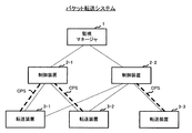
図1に示すように、本パケット転送システムは、監視マネージャ1と、制御装置2−1〜2−2と、転送装置3−1〜3−3とから構成される。
As shown in FIG. 1, the present packet transfer system includes a
なお、制御装置2−1〜2−2、転送装置3−1〜3−3それぞれの台数は、任意でよい。また、制御装置2−1〜2−2同士または転送装置3−1〜3−3同士は、それぞれ独立した筺体で構成するに限らず、同一の筺体内に収容された構成を有していてもよい。 The numbers of the control devices 2-1 to 2-2 and the transfer devices 3-1 to 3-3 may be arbitrary. Further, the control devices 2-1 to 2-2 or the transfer devices 3-1 to 3-3 are not limited to being configured by independent housings, but have a configuration accommodated in the same housing. Also good.
監視マネージャ1は、制御装置2−1〜2−2の負荷状態を監視する。
The
制御装置2−1〜2−2それぞれは、転送装置3−1〜3−3それぞれと接続可能に構成されており、自己と接続されている転送装置3−1〜3−3の制御を行う。 Each of the control devices 2-1 to 2-2 is configured to be connectable to each of the transfer devices 3-1 to 3-3 and controls the transfer devices 3-1 to 3-3 connected to itself. .
なお、図1に示した破線は、制御装置2−1と転送装置3−1〜3−2とが制御用プロトコルセッションCPSによって接続されており、制御装置2−2と転送装置3−3とが制御用プロトコルセッションCPSによって接続されていることを表している。つまり、制御装置2−1が転送装置3−1〜3−2を制御しており、制御装置2−2が転送装置3−3を制御している。 1 indicates that the control device 2-1 and the transfer devices 3-1 to 3-2 are connected by the control protocol session CPS, and the control device 2-2 and the transfer device 3-3 are connected to each other. Is connected by the control protocol session CPS. That is, the control device 2-1 controls the transfer devices 3-1 to 3-2, and the control device 2-2 controls the transfer device 3-3.
ここで、制御用プロトコルセッションCPSとは、制御装置2−1〜2−2が、転送装置3−1〜3−3を制御する際の通信に用いられるセッションである。 Here, the control protocol session CPS is a session used for communication when the control devices 2-1 to 2-2 control the transfer devices 3-1 to 3-3.
転送装置3−1〜3−3は、複数の入力回線と複数の出力回線とをそれぞれ収容している。転送装置3−1〜3−3は、例えば、ルータであり、自己が収容する入力回線から送信されてきたパケットを、通信経路が示されている経路表に基づいて、自己が収容する出力回線の少なくとも1つへ転送する役割を果たす。 The transfer devices 3-1 to 3-3 accommodate a plurality of input lines and a plurality of output lines, respectively. The transfer apparatuses 3-1 to 3-3 are, for example, routers, and output lines that are accommodated by the packets based on the route table in which communication paths are indicated, for packets transmitted from the input lines accommodated by the transfer apparatuses 3-1 to 3-3. The role of forwarding to at least one of the
つぎに、図1に示した監視マネージャ1の構成について、詳細に説明する。
Next, the configuration of the
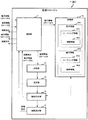
図2に示すように、監視マネージャ1は、通信部11と、比較部12と、決定部13と、制御指示部14と、接続指示部15と、記憶部16とを有する。
As illustrated in FIG. 2, the
通信部11は、制御装置2−1〜2−2それぞれから送信されてきた負荷情報LD1〜LD2を受信する。
The
ここで、「負荷情報LD1〜LD2」とは、制御装置2−1〜2−2がそれぞれ具備するCPU(Central Processing Unit)の使用率、制御装置2−1〜2−2の消費電力などを示す情報である。 Here, the “load information LD1 to LD2” refers to a usage rate of a CPU (Central Processing Unit) included in each of the control devices 2-1 to 2-2, power consumption of the control devices 2-1 to 2-2, and the like. It is information to show.
また、通信部11は、制御装置2−1〜2−2から送信されてきた動作情報OP1〜OP2を受信する。
Further, the
ここで、「動作情報OP1〜OP2」は、例えば、制御装置2−1〜2−2それぞれが制御している転送装置がパケットを転送するためのルーティング情報RT1〜RT2(「経路表」)をそれぞれ含んでいる。 Here, the “operation information OP1 to OP2” includes, for example, routing information RT1 to RT2 (“route table”) for transferring a packet by a transfer device controlled by each of the control devices 2-1 to 2-2. Includes each.
また、「動作情報OP1〜OP2」は、例えば、制御装置2−1〜2−2それぞれが制御している転送装置(例えば、転送装置に付与されたIPアドレスなど)や転送装置の接続形態(トポロジーなど)を示す制御情報MG1〜MG2を含んでいる。図1に示した例では、制御装置2−1は、自己が制御している転送装置3−1〜3−2を示す制御情報MG1を送信する。また、図1に示した例では、制御装置2−2は、自己が制御している転送装置3−3を示す制御情報MG2を送信する。なお、制御装置2−1〜2−2は、その定常動作中において、動作情報OP1〜OP2を保持している。 The “operation information OP1 to OP2” is, for example, a transfer device (for example, an IP address assigned to the transfer device) controlled by each of the control devices 2-1 to 2-2 or a connection form of the transfer device ( Control information MG1 and MG2 indicating topology etc.). In the example illustrated in FIG. 1, the control device 2-1 transmits control information MG <b> 1 indicating the transfer devices 3-1 to 3-2 controlled by itself. In the example illustrated in FIG. 1, the control device 2-2 transmits control information MG2 indicating the transfer device 3-3 controlled by itself. Note that the control devices 2-1 to 2-2 hold operation information OP1 to OP2 during the steady operation.
また、通信部11は、制御指示を制御装置2−1〜2−2へ送信する。
Further, the
ここで、「制御指示」とは、高負荷状態にある制御装置以外の制御装置に対して、高負荷状態にある制御装置が制御している転送装置の制御を指示するための信号である。 Here, the “control instruction” is a signal for instructing control devices other than the control device in the high load state to control the transfer device controlled by the control device in the high load state.
ここでいう「高負荷状態」とは、転送装置と接続された制御装置において、該転送装置の制御を処理する速度が著しく遅延したり、その遅延によってタイムアウトが発生してしまうことを指す。 Here, the “high load state” means that in the control device connected to the transfer device, the speed of processing of the transfer device is significantly delayed or a timeout occurs due to the delay.
また、通信部11(「動作情報転送部」)は、高負荷状態ではない制御装置(図1の例では、制御装置2−2)に対して制御指示を送信する場合、高負荷状態にある制御装置(図1の例では、制御装置2−1)についての動作情報(図1の例では、動作情報OP1)を送信する。 Further, the communication unit 11 (“operation information transfer unit”) is in a high load state when transmitting a control instruction to a control device that is not in a high load state (the control device 2-2 in the example of FIG. 1). Operation information (operation information OP1 in the example of FIG. 1) about the control device (control device 2-1 in the example of FIG. 1) is transmitted.
また、通信部11は、接続指示を転送装置3−1〜3−3へ送信する。
Further, the
ここで、「接続指示」とは、決定部13が決定した制御装置への接続を指示するための信号である。
Here, the “connection instruction” is a signal for instructing connection to the control device determined by the
比較部12は、転送装置と接続された制御装置それぞれから送信されてきた負荷情報LD1またはLD2が示す各負荷と、制御装置が高負荷状態にあるかどうかを判別する基準となる負荷基準値(「所定値」)とを比較する。
The
なお、制御装置2−1〜2−2それぞれは、互いに異なる負荷情報を送信するように構成されていてもよい。例えば、制御装置2−1がCPUおよびメモリの各使用率を負荷情報LD1として送信し、制御装置2−2が消費電力のみを負荷情報LD2として送信するように構成されていてもよい。この場合、比較部12は、それぞれの負荷情報LD1またはLD2に含まれている値を用いて制御装置2−1または2−2それぞれの負荷として算出した上で、負荷基準値との比較を行ってもよい。
Each of the control devices 2-1 to 2-2 may be configured to transmit different load information. For example, the control device 2-1 may be configured to transmit each usage rate of the CPU and the memory as the load information LD1, and the control device 2-2 may transmit only the power consumption as the load information LD2. In this case, the
決定部13は、比較部12による比較の結果、負荷が負荷基準値よりも大きい場合、高負荷状態にある制御装置(例えば、制御装置2−1)以外の高負荷状態にない制御装置(例えば、制御装置2−2)を、高負荷状態にある制御装置が制御している転送装置(図1に示した例では、転送装置3−1〜3−2)を制御する新たな制御装置に決定する。
When the
制御指示部14は、制御指示を通信部11へ出力する。通信部11は、決定部13により決定された新たな制御装置へ、制御指示を送信する。
The
また、制御指示部14は、制御指示を出力する場合、負荷が負荷基準値よりも大きな制御装置(例えば、制御装置2−1)についての動作情報OP1を記憶部16から読み出す。そして、制御指示部14は、読み出した動作情報OP1を通信部11へ出力する。通信部11は、制御指示および動作情報OP1を、決定部13が決定した制御装置2−2へ送信する。
Further, when outputting the control instruction, the
接続指示部15は、決定部13が決定した制御装置(例えば、転送装置3−1〜3−2と接続されていない制御装置2−2)への接続を、高負荷状態が発生している制御装置2−1が制御している転送装置3−1〜3−2へ指示する。当該指示を行う場合、接続指示部15は、接続指示を通信部11へ出力する。通信部11は、高負荷状態にある制御装置を介して、接続指示を転送装置3−1〜3−2へ送信する。
The
記憶部16は、任意の情報を記憶可能である。記憶部16は、例えば、制御装置2−1〜2−2から送信されてきた動作情報OP1〜OP2(ルーティング情報RT1〜RT2や制御情報MG1〜MG2を含む)を記憶する。
The
つぎに、図1に示した制御装置2−1〜2−2の構成について、詳細に説明する。なお、制御装置2−1〜2−2は互いに同一の構成を有するため、以下では、制御装置2−1が有する構成を例に挙げて説明する。 Next, the configuration of the control devices 2-1 to 2-2 shown in FIG. 1 will be described in detail. Since the control devices 2-1 to 2-2 have the same configuration, the configuration of the control device 2-1 will be described below as an example.
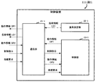
図3に示すように、制御装置2−1は、通信部21−1と、負荷測定部22−1と、制御部23−1とを有する。 As illustrated in FIG. 3, the control device 2-1 includes a communication unit 21-1, a load measurement unit 22-1, and a control unit 23-1.
通信部21−1は、例えば、通信モジュールで構成され、監視マネージャ1または転送装置3−1〜3−3との間でパケットの送受信を行う。
The communication unit 21-1 includes, for example, a communication module, and transmits and receives packets to and from the
例えば、通信部21−1は、負荷測定部22−1から出力されてきた負荷情報LD1を監視マネージャ1へ送信する。
For example, the communication unit 21-1 transmits the load information LD1 output from the load measurement unit 22-1 to the
また、通信部21−1(「動作情報送信部」)は、制御部23−1から出力されてきた動作情報OP1を監視マネージャ1へ送信する。動作情報OP1は、ルーティング情報RT1や制御情報MG1を含んでいる。
Further, the communication unit 21-1 (“operation information transmission unit”) transmits the operation information OP1 output from the control unit 23-1 to the
また、通信部21−1は、監視マネージャ1から送信されてきた制御指示を受信する。
In addition, the communication unit 21-1 receives the control instruction transmitted from the
また、通信部21−1は、転送装置3−1〜3−3から送信されてきた接続要求を受信する。図1に示した例では、制御装置2−1が具備する通信部21−1は、転送装置3−3から送信されてきた接続要求を受信する。また、制御装置2−2が具備する通信部21−2は、転送装置3−1〜3−2から送信されてきた接続要求を受信する。 Further, the communication unit 21-1 receives the connection request transmitted from the transfer devices 3-1 to 3-3. In the example illustrated in FIG. 1, the communication unit 21-1 included in the control device 2-1 receives the connection request transmitted from the transfer device 3-3. In addition, the communication unit 21-2 included in the control device 2-2 receives the connection request transmitted from the transfer devices 3-1 to 3-2.
なお、「接続要求」とは、転送装置3−1〜3−3が制御装置2−1または2−2への接続を要求する信号である。 The “connection request” is a signal that the transfer devices 3-1 to 3-3 request to connect to the control device 2-1 or 2-2.
負荷測定部22−1は、制御装置2−1が具備するCPU(図示せず)の使用率や制御装置2−1の消費電力を一定期間ごとに測定し、測定したCPUの使用率や消費電力を示す負荷情報LD1を通信部21−1へ出力する。 The load measuring unit 22-1 measures the usage rate of the CPU (not shown) included in the control device 2-1 and the power consumption of the control device 2-1, and measures the usage rate and consumption of the measured CPU. Load information LD1 indicating power is output to the communication unit 21-1.
制御部23−1は、「制御処理」を実行し、転送装置3−1〜3−3が接続要求を送信してきた場合、該接続要求をしてきた転送装置3−1〜3−3と接続した上で、該接続した転送装置3−1〜3−3を制御する。 When the control unit 23-1 executes “control processing” and the transfer apparatuses 3-1 to 3-3 transmit a connection request, the control unit 23-1 connects to the transfer apparatuses 3-1 to 3-3 that have made the connection request. Then, the connected transfer devices 3-1 to 3-3 are controlled.
ここでいう、転送装置3−1〜3−3の制御とは、制御装置2−1が制御を行う転送装置の情報を更新することである。 Here, the control of the transfer apparatuses 3-1 to 3-3 is to update the information of the transfer apparatus that is controlled by the control apparatus 2-1.
また、上述した制御とは、例えば、転送装置3−1〜3−3が受信するパケットのルーティング情報RT1〜3を決定するプロトコル信号パケット終端処理を行うことである。 The above-described control is, for example, performing protocol signal packet termination processing for determining routing information RT1 to RT3 of packets received by the transfer apparatuses 3-1 to 3-3.
また、上述した制御とは、例えば、プロトコル信号の処理により転送装置3−1〜3−3が記憶しているルーティング情報RT1〜RT3を作成することである。図1に示した例では、制御装置2−1により制御されている転送装置3−1〜3−2それぞれは、制御部23−1(情報生成部)が生成したルーティング情報RT1〜RT2を反映させることにより、自己が記憶しているルーティング情報RT1〜RT2を更新する。 The above-described control is, for example, creating routing information RT1 to RT3 stored in the transfer apparatuses 3-1 to 3-3 by processing protocol signals. In the example illustrated in FIG. 1, each of the transfer devices 3-1 to 3-2 controlled by the control device 2-1 reflects the routing information RT <b> 1 to RT <b> 2 generated by the control unit 23-1 (information generation unit). By doing so, the routing information RT1 to RT2 stored therein is updated.
また、制御部23−1(動作設定部)は、制御装置2−1と異なる制御装置2−2の動作情報OP2を監視マネージャ1が送信してきた場合、当該動作情報OP2が示す設定内容に従って、転送装置を制御するための設定内容を変更する。
In addition, when the
なお、図1に示した例では、制御装置2−2が具備する制御部23−2は、動作情報OP1が示す設定内容に従って、制御装置2−1が制御している転送装置3−1〜3−2の制御を行えるように、転送装置の設定内容を変更する。
In the example illustrated in FIG. 1, the control unit 23-2 included in the control device 2-2 includes the transfer devices 3-1 to 3-1 controlled by the control device 2-1 according to the setting content indicated by the
つぎに、図1に示した転送装置3−1〜3−3の構成について、詳細に説明する。なお、転送装置3−1〜3−3は互いに同一の構成を有するため、以下では、転送装置3−1が有する構成を例に挙げて説明する。 Next, the configuration of the transfer apparatuses 3-1 to 3-3 shown in FIG. 1 will be described in detail. Since the transfer devices 3-1 to 3-3 have the same configuration, the configuration of the transfer device 3-1 will be described below as an example.
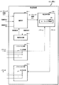
図4に示すように、転送装置3−1は、通信部31−1と、接続要求部32−1と、パケット入力部33−1と、パケット出力部34−1と転送処理部35−1とを有する。 As illustrated in FIG. 4, the transfer device 3-1 includes a communication unit 31-1, a connection request unit 32-1, a packet input unit 33-1, a packet output unit 34-1, and a transfer processing unit 35-1. And have.
通信部31−1は、監視マネージャ1から送信されてきた接続指示を受信する。
The communication unit 31-1 receives the connection instruction transmitted from the
また、通信部31−1は、制御装置2−1または2−2から送信されてきたルーティング情報RT1を受信する。ここに、ルーティング情報RT1は、転送装置3−1がパケットの転送を行うための「経路表」である。 Further, the communication unit 31-1 receives the routing information RT1 transmitted from the control device 2-1 or 2-2. Here, the routing information RT1 is a “route table” for the transfer device 3-1 to transfer the packet.
また、通信部31−1は、接続要求部32−1から出力されてきた接続要求を、接続指示が指示する制御装置(図1の例では、制御装置2−2)へ送信する。 The communication unit 31-1 transmits the connection request output from the connection request unit 32-1 to the control device (control device 2-2 in the example of FIG. 1) indicated by the connection instruction.
接続要求部32−1は、監視マネージャ1から、制御用プロトコルセッションCPSを経由して接続している制御装置(図1の例では、制御装置2−1)以外の制御装置(図1の例では、制御装置2−2)への接続指示が送信されてきた場合、該接続指示により指示された制御装置2−2へ接続を要求する。
The connection request unit 32-1 is connected to the control device (example of FIG. 1) other than the control device (control device 2-1 in the example of FIG. 1) connected from the
パケット入力部33−1は、複数の入力回線を収容し、パケット出力部34−1は、複数の出力回線を収容する。なお、パケット入力部33−1とパケット出力部34−1とは、入出力回線対応部を構成する。 The packet input unit 33-1 accommodates a plurality of input lines, and the packet output unit 34-1 accommodates a plurality of output lines. The packet input unit 33-1 and the packet output unit 34-1 constitute an input / output line corresponding unit.
転送処理部35−1は、ルーティング情報RT1を記憶している。 The transfer processing unit 35-1 stores routing information RT1.
また、転送処理部35−1は、入力回線から受信したパケットのヘッダ情報とルーティング情報RT1とに基づいて、入力回線から受信したパケットを少なくとも1つの出力回線へ出力する。 Further, the transfer processing unit 35-1 outputs the packet received from the input line to at least one output line based on the header information of the packet received from the input line and the routing information RT1.
また、転送処理部35−1は、当該転送装置3−1自身を通過するパケットに対して所定の処理を施す。 Further, the transfer processing unit 35-1 performs a predetermined process on the packet passing through the transfer device 3-1.
つぎに、上記構成を有するパケット転送システムが、制御装置2−1〜2−2の負荷に基づいて、転送装置3−1〜3−3の負荷分散を制御する動作を説明する。 Next, an operation in which the packet transfer system having the above configuration controls the load distribution of the transfer apparatuses 3-1 to 3-3 based on the loads of the control apparatuses 2-1 to 2-2 will be described.
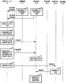
図5に示すように、制御装置2−1は、動作情報OP1と、負荷情報LD1とを、監視マネージャ1へ送信する(ステップS1)。ここで、動作情報OP1は、転送装置3−1〜3−2のルーティング情報RT1〜RT2と、該制御装置2−1が制御している転送装置3−1〜3−2を示す制御情報MG1とを含んでいる。 As shown in FIG. 5, the control device 2-1 transmits the operation information OP1 and the load information LD1 to the monitoring manager 1 (step S1). Here, the operation information OP1 includes the routing information RT1 to RT2 of the transfer devices 3-1 to 2-3, and the control information MG1 indicating the transfer devices 3-1 to 3-2 controlled by the control device 2-1. Including.
また、制御装置2−2は、動作情報OP2と、負荷情報LD2とを、監視マネージャ1へ送信する(ステップS2)。ここで、動作情報OP2は、転送装置3−3のルーティング情報RT3と、該制御装置2−2が制御している転送装置3−3を示す制御情報MG2とを含んでいる。 Further, the control device 2-2 transmits the operation information OP2 and the load information LD2 to the monitoring manager 1 (step S2). Here, the operation information OP2 includes routing information RT3 of the transfer device 3-3 and control information MG2 indicating the transfer device 3-3 controlled by the control device 2-2.
監視マネージャ1は、制御装置2−1から送信されてきた負荷情報LD1または制御装置2−2から送信されてきた負荷情報LD2が示す負荷それぞれと負荷基準値とを比較する。当該比較により、監視マネージャ1は、制御装置2−1または制御装置2−2が高負荷状態にあるかどうかを判別する(ステップS3)。
The
比較の結果、例えば、制御装置2−1の負荷が負荷基準値よりも大きい場合には、制御装置2−1が高負荷状態にあると判別する。この場合、監視マネージャ1は、高負荷状態にあると判別された制御装置2−1以外の制御装置2−2を、高負荷状態にあると判別された制御装置2−1が制御している転送装置3−1〜3−2の少なくとも一部を制御する制御装置に決定する(ステップS4)。図5に示した例では、監視マネージャ1は、制御装置2−1が制御している転送装置3−2の新たな制御装置を、制御装置2−2に決定する。
As a result of the comparison, for example, when the load of the control device 2-1 is larger than the load reference value, it is determined that the control device 2-1 is in a high load state. In this case, the
続いて、監視マネージャ1は、新たな制御装置に決定された制御装置へ、制御指示を送信する(ステップS5)。
Subsequently, the
さらに、監視マネージャ1は、高負荷状態にあると判別された制御装置2−1から送信されてきた動作情報OP1を制御装置2−2へ送信する(ステップS6)。
Furthermore, the
制御装置2−2は、制御指示を受信した場合、高負荷状態にあると判別された制御装置2−1が制御している転送装置(図5の例では、転送装置3−2)を制御可能なように、動作情報OP1を用いて転送装置制御用の設定を行う(ステップS7)。 When the control device 2-2 receives the control instruction, the control device 2-2 controls the transfer device (the transfer device 3-2 in the example of FIG. 5) controlled by the control device 2-1 determined to be in the high load state. As much as possible, setting for transfer device control is performed using the operation information OP1 (step S7).
監視マネージャ1は、新たな制御装置として決定した制御装置2−2への接続を、制御装置2−1が制御している転送装置の少なくとも一部(図5に示した例では、転送装置3−2)に指示する。当該指示を行う場合、監視マネージャ1は、接続指示を転送装置3−2へ送信する(ステップS8)。
The
転送装置3−2は、監視マネージャ1から送信されてきた接続指示を受信した場合、該接続指示により指示された制御装置2−2に対して接続要求を送信する(ステップS9)。
When the transfer device 3-2 receives the connection instruction transmitted from the
制御装置2−2は、転送装置3−2から送信されてきた送信要求を受信した場合、自己が現在制御している転送装置3−3に加えて、転送装置3−2の制御を新たに開始する(ステップS10)。 When the control device 2-2 receives a transmission request transmitted from the transfer device 3-2, the control device 2-2 newly controls the transfer device 3-2 in addition to the transfer device 3-3 currently controlled by the control device 2-2. Start (step S10).
なお、図6に示すように、制御装置2−2は、制御用プロトコルセッションCPSを介して通信することにより、転送装置3−2の制御を行う。 Note that, as illustrated in FIG. 6, the control device 2-2 controls the transfer device 3-2 by communicating via the control protocol session CPS.
以上で、本発明のパケット転送システムが、制御装置2−1〜2−2の負荷に基づいて、転送装置3−1〜3−3の負荷分散を制御するための一連の動作が終了する。 With the above, a series of operations for controlling the load distribution of the transfer apparatuses 3-1 to 3-3 by the packet transfer system of the present invention based on the loads of the control apparatuses 2-1 to 2-2 is completed.
以上説明したように、本発明のパケット転送システムによれば、監視マネージャ1は、制御装置2−1における高負荷状態の発生を検出した場合、当該制御装置2−1が制御している転送装置3−1〜3−2の少なくとも一部の新たな制御装置(図6に示した例では、制御装置2−2)を、制御装置2−1以外の制御装置のなかから新たに決定する。続いて、監視マネージャ1は、新たな制御装置に決定した制御装置2−2へ、制御装置2−1から受信した動作情報OP1を送信する。制御装置2−2は、監視マネージャ1から送信されてきた動作情報OP1を用いて設定内容を変更する。監視マネージャ1は、制御装置2−1によって制御されていた転送装置の少なくとも一部(図6の例では、転送装置3−2)へ、接続指示を送信する。当該接続指示を受信した転送装置3−2は、該接続指示が示す制御装置2−2へ接続要求を送信する。制御装置2−2は、接続要求を送信してきた転送装置3−2の制御を開始する。
As described above, according to the packet transfer system of the present invention, when the
これにより、転送装置と接続されていて該転送装置を制御している制御装置において高負荷状態が発生した場合でも、パケット転送システムに対する影響を抑制することができる。つまり、サーバ(制御装置)の負荷分散による信頼性を高くすることができる。 Thereby, even when a high load state occurs in the control device connected to the transfer device and controlling the transfer device, it is possible to suppress the influence on the packet transfer system. That is, it is possible to increase the reliability by load distribution of the server (control device).
1 監視マネージャ
11 通信部
12 比較部
13 決定部
14 制御指示部
15 接続指示部
16 記憶部
2−1、2−2 制御装置
21−1 通信部
22−1 負荷測定部
23−1 制御部
3−1、3−2、3−3 転送装置
31−1 通信部
32−1 接続要求部
33−1 パケット入力部
34−1 パケット出力部
35−1 転送処理部
DESCRIPTION OF
Claims (4)
前記監視マネージャは、
前記複数の制御装置のうち、前記転送装置と接続された制御装置の負荷と所定値とを比較する比較部と、
前記比較の結果、前記負荷が前記所定値よりも大きい場合、前記転送装置と接続された制御装置以外の制御装置を、該転送装置を制御する制御装置に決定する決定部と、
前記転送装置へ、前記決定した制御装置への接続を指示する接続指示部とを有し、
前記転送装置は、前記監視マネージャから前記決定した制御装置への接続を指示された場合、該制御装置へ接続要求を行う接続要求部を有し、
前記制御装置は、前記転送装置から接続要求された場合、該転送装置と接続する制御部を有することを特徴とするパケット転送システム。 A transfer device that transfers an input packet based on a route table indicating a communication route of the packet, and a plurality of devices that are connectable to the transfer device and control the transfer device when connected to the transfer device A packet transfer system comprising a control device and a monitoring manager for monitoring a load state of the plurality of control devices,
The monitoring manager
Of the plurality of control devices, a comparison unit that compares a predetermined value with a load of the control device connected to the transfer device;
As a result of the comparison, when the load is greater than the predetermined value, a determination unit that determines a control device other than the control device connected to the transfer device as a control device that controls the transfer device;
A connection instruction unit for instructing the transfer device to connect to the determined control device;
The transfer device has a connection request unit that makes a connection request to the control device when instructed to connect to the determined control device from the monitoring manager;
The control device includes a control unit that connects to the transfer device when a connection request is received from the transfer device.
前記制御装置は、
前記転送装置と接続された場合、該転送装置を制御するための動作情報を前記監視マネージャへ送信する動作情報送信部を有し、
前記制御部は、前記決定部により前記転送装置を制御する制御装置に決定された場合、該監視マネージャから送信されてきた動作情報を用いて前記転送装置の制御を行い、
前記監視マネージャは、
前記転送装置と接続された制御装置から送信されてきた動作情報を、前記決定部が決定した制御装置へ送信する動作情報転送部を有することを特徴とするパケット転送システム。 The packet transfer system according to claim 1, wherein
The control device includes:
When connected to the transfer device, the device has an operation information transmission unit for transmitting operation information for controlling the transfer device to the monitoring manager;
When the control unit is determined by the determination unit to control the transfer device, the control unit controls the transfer device using operation information transmitted from the monitoring manager,
The monitoring manager
A packet transfer system, comprising: an operation information transfer unit that transmits operation information transmitted from a control device connected to the transfer device to the control device determined by the determination unit.
前記監視マネージャが、前記複数の制御装置のうち、前記転送装置と接続された制御装置の負荷と所定値とを比較する処理と、
前記監視マネージャが、前記比較の結果、前記負荷が前記所定値よりも大きい場合、前記転送装置と接続された制御装置以外の制御装置を、該転送装置を制御する制御装置に決定する決定処理と、
前記監視マネージャが、前記転送装置へ、前記決定した制御装置への接続を指示する処理と、
前記転送装置が、前記監視マネージャから前記決定した制御装置への接続を指示された場合、該制御装置へ接続要求を行う処理と、
前記制御装置が、前記転送装置から接続要求された場合、該転送装置と接続する制御処理とを有することを特徴とするパケット転送方法。 A transfer device that transfers an input packet based on a route table indicating a communication route of the packet, and a plurality of devices that are connectable to the transfer device and control the transfer device when connected to the transfer device A packet transfer method in a packet transfer system comprising a control device and a monitoring manager for monitoring a load state of the plurality of control devices,
A process in which the monitoring manager compares a load of a control device connected to the transfer device and a predetermined value among the plurality of control devices;
A determination process for determining, when the load is greater than the predetermined value as a result of the comparison, a control device other than the control device connected to the transfer device as a control device that controls the transfer device; ,
A process in which the monitoring manager instructs the transfer device to connect to the determined control device;
When the transfer device is instructed by the monitoring manager to connect to the determined control device, a process of making a connection request to the control device;
A packet transfer method comprising: a control process for connecting to the transfer device when the control device requests connection from the transfer device.
前記制御装置が、前記転送装置と接続された場合、該転送装置を制御するための動作情報を前記監視マネージャへ送信する処理と、
前記監視マネージャが、前記転送装置と接続された制御装置から送信されてきた動作情報を、前記決定処理にて決定した制御装置へ送信する処理とを有し、
前記制御処理では、前記決定処理により前記転送装置を制御する制御装置に決定された場合、該監視マネージャから送信されてきた動作情報を用いて前記転送装置の制御を行うことを特徴とするパケット転送方法。 The packet transfer method according to claim 3, wherein
When the control device is connected to the transfer device, a process of transmitting operation information for controlling the transfer device to the monitoring manager;
The monitoring manager has a process of transmitting the operation information transmitted from the control apparatus connected to the transfer apparatus to the control apparatus determined in the determination process,
In the control process, when it is determined by the determination process to be a control apparatus that controls the transfer apparatus, the transfer apparatus is controlled using the operation information transmitted from the monitoring manager. Method.
Priority Applications (1)
| Application Number | Priority Date | Filing Date | Title |
|---|---|---|---|
| JP2008206910A JP4559512B2 (en) | 2008-08-11 | 2008-08-11 | Packet transfer system and packet transfer method |
Applications Claiming Priority (1)
| Application Number | Priority Date | Filing Date | Title |
|---|---|---|---|
| JP2008206910A JP4559512B2 (en) | 2008-08-11 | 2008-08-11 | Packet transfer system and packet transfer method |
Publications (2)
| Publication Number | Publication Date |
|---|---|
| JP2010045503A true JP2010045503A (en) | 2010-02-25 |
| JP4559512B2 JP4559512B2 (en) | 2010-10-06 |
Family
ID=42016541
Family Applications (1)
| Application Number | Title | Priority Date | Filing Date |
|---|---|---|---|
| JP2008206910A Expired - Fee Related JP4559512B2 (en) | 2008-08-11 | 2008-08-11 | Packet transfer system and packet transfer method |
Country Status (1)
| Country | Link |
|---|---|
| JP (1) | JP4559512B2 (en) |
Cited By (7)
| Publication number | Priority date | Publication date | Assignee | Title |
|---|---|---|---|---|
| JP2013030863A (en) * | 2011-07-27 | 2013-02-07 | Nec Corp | Switch device control system, and device and method for controlling configuration thereof |
| WO2013187054A1 (en) * | 2012-06-14 | 2013-12-19 | Nec Corporation | Communication system, control apparatus, communication method, control method and program |
| JP2014135614A (en) * | 2013-01-09 | 2014-07-24 | Kddi Corp | Management device and program for communication network controller |
| WO2014133025A1 (en) * | 2013-02-27 | 2014-09-04 | 日本電気株式会社 | Communication system, host controller, network control method, and program |
| JPWO2013146785A1 (en) * | 2012-03-28 | 2015-12-14 | 日本電気株式会社 | COMMUNICATION SYSTEM, COMMUNICATION DEVICE, CONTROL DEVICE, COMMUNICATION DEVICE CONTROL METHOD, AND PROGRAM |
| JP2016021656A (en) * | 2014-07-14 | 2016-02-04 | 富士通株式会社 | Load distribution device, session management system, and load distribution method |
| JP2016506193A (en) * | 2013-12-05 | 2016-02-25 | 華為技術有限公司Huawei Technologies Co.,Ltd. | Control method, control apparatus and processor in software definition network |
Citations (1)
| Publication number | Priority date | Publication date | Assignee | Title |
|---|---|---|---|---|
| JP2003199136A (en) * | 2001-12-26 | 2003-07-11 | Nec Commun Syst Ltd | Load distribution system for base station controller |
-
2008
- 2008-08-11 JP JP2008206910A patent/JP4559512B2/en not_active Expired - Fee Related
Patent Citations (1)
| Publication number | Priority date | Publication date | Assignee | Title |
|---|---|---|---|---|
| JP2003199136A (en) * | 2001-12-26 | 2003-07-11 | Nec Commun Syst Ltd | Load distribution system for base station controller |
Cited By (13)
| Publication number | Priority date | Publication date | Assignee | Title |
|---|---|---|---|---|
| JP2013030863A (en) * | 2011-07-27 | 2013-02-07 | Nec Corp | Switch device control system, and device and method for controlling configuration thereof |
| JPWO2013146785A1 (en) * | 2012-03-28 | 2015-12-14 | 日本電気株式会社 | COMMUNICATION SYSTEM, COMMUNICATION DEVICE, CONTROL DEVICE, COMMUNICATION DEVICE CONTROL METHOD, AND PROGRAM |
| US10454805B2 (en) | 2012-03-28 | 2019-10-22 | Nec Corporation | Communication system, communication apparatus, control apparatus, communication apparatus control method and program |
| US10212084B2 (en) | 2012-06-14 | 2019-02-19 | Nec Corporation | Communication system, control apparatus, communication method, control method and program |
| WO2013187054A1 (en) * | 2012-06-14 | 2013-12-19 | Nec Corporation | Communication system, control apparatus, communication method, control method and program |
| CN104365069A (en) * | 2012-06-14 | 2015-02-18 | 日本电气株式会社 | Communication system, control apparatus, communication method, control method and program |
| JP2015519765A (en) * | 2012-06-14 | 2015-07-09 | 日本電気株式会社 | COMMUNICATION SYSTEM, CONTROL DEVICE, COMMUNICATION METHOD, CONTROL METHOD, AND PROGRAM |
| JP2014135614A (en) * | 2013-01-09 | 2014-07-24 | Kddi Corp | Management device and program for communication network controller |
| WO2014133025A1 (en) * | 2013-02-27 | 2014-09-04 | 日本電気株式会社 | Communication system, host controller, network control method, and program |
| US9344511B2 (en) | 2013-12-05 | 2016-05-17 | Huawei Technologies Co., Ltd. | Control method, control device, and process in software defined network |
| US9432474B2 (en) | 2013-12-05 | 2016-08-30 | Huawei Technologies Co., Ltd. | Control method, control device, and processor in software defined network |
| JP2016506193A (en) * | 2013-12-05 | 2016-02-25 | 華為技術有限公司Huawei Technologies Co.,Ltd. | Control method, control apparatus and processor in software definition network |
| JP2016021656A (en) * | 2014-07-14 | 2016-02-04 | 富士通株式会社 | Load distribution device, session management system, and load distribution method |
Also Published As
| Publication number | Publication date |
|---|---|
| JP4559512B2 (en) | 2010-10-06 |
Similar Documents
| Publication | Publication Date | Title |
|---|---|---|
| JP4559512B2 (en) | Packet transfer system and packet transfer method | |
| JP5846221B2 (en) | Network system and topology management method | |
| JP4840236B2 (en) | Network system and node device | |
| US9065768B2 (en) | Apparatus for a high performance and highly available multi-controllers in a single SDN/OpenFlow network | |
| JP6007976B2 (en) | Communication system, controller, communication method and program | |
| JP2017028698A (en) | Traffic switching method, device, and system | |
| WO2012068996A1 (en) | Method and device for detecting link state | |
| KR20120036903A (en) | Inter-node link aggregation system and method | |
| JP5861772B2 (en) | Network appliance redundancy system, control device, network appliance redundancy method and program | |
| US10320653B2 (en) | Route topology discovery in data networks | |
| CN103957158A (en) | Determining method and device for flow forwarding path and communication system | |
| JP4559511B2 (en) | Packet transfer system and packet transfer method | |
| WO2011137797A1 (en) | Method and system for data transmission in ethernet | |
| WO2012092885A2 (en) | Method and device for adjusting ip network load | |
| JP5817078B2 (en) | Transmission system, centralized control computer, and transmission method | |
| WO2019170085A1 (en) | Fault diagnosis method and apparatus therefor | |
| US8750166B2 (en) | Route topology discovery in data networks | |
| KR20180122513A (en) | Method and framework for traffic engineering in network hypervisor of sdn-based network virtualization platform | |
| JP5929720B2 (en) | Communication system and network relay device | |
| JP2002319957A (en) | Network repeater, port monitoring method and program for making computer execute the method | |
| JP2008153939A (en) | Network repeater and its control method | |
| JP2003218916A (en) | Front end processor and routing management method | |
| JP2004525565A (en) | Improved telecommunications network | |
| CN105765903A (en) | Topology discovery method and device | |
| JP4630298B2 (en) | Function distributed communication apparatus, component element coupling control method, and program |
Legal Events
| Date | Code | Title | Description |
|---|---|---|---|
| A131 | Notification of reasons for refusal |
Free format text: JAPANESE INTERMEDIATE CODE: A131 Effective date: 20100426 |
|
| A521 | Written amendment |
Free format text: JAPANESE INTERMEDIATE CODE: A523 Effective date: 20100614 |
|
| TRDD | Decision of grant or rejection written | ||
| A01 | Written decision to grant a patent or to grant a registration (utility model) |
Free format text: JAPANESE INTERMEDIATE CODE: A01 Effective date: 20100630 |
|
| A01 | Written decision to grant a patent or to grant a registration (utility model) |
Free format text: JAPANESE INTERMEDIATE CODE: A01 |
|
| A61 | First payment of annual fees (during grant procedure) |
Free format text: JAPANESE INTERMEDIATE CODE: A61 Effective date: 20100722 |
|
| R150 | Certificate of patent or registration of utility model |
Free format text: JAPANESE INTERMEDIATE CODE: R150 |
|
| FPAY | Renewal fee payment (event date is renewal date of database) |
Free format text: PAYMENT UNTIL: 20130730 Year of fee payment: 3 |
|
| S531 | Written request for registration of change of domicile |
Free format text: JAPANESE INTERMEDIATE CODE: R313531 |
|
| R350 | Written notification of registration of transfer |
Free format text: JAPANESE INTERMEDIATE CODE: R350 |
|
| LAPS | Cancellation because of no payment of annual fees |