JP2010045453A - Apparatus, method, and program for electronic watermark detection - Google Patents
Apparatus, method, and program for electronic watermark detection Download PDFInfo
- Publication number
- JP2010045453A JP2010045453A JP2008206293A JP2008206293A JP2010045453A JP 2010045453 A JP2010045453 A JP 2010045453A JP 2008206293 A JP2008206293 A JP 2008206293A JP 2008206293 A JP2008206293 A JP 2008206293A JP 2010045453 A JP2010045453 A JP 2010045453A
- Authority
- JP
- Japan
- Prior art keywords
- histogram
- input image
- image
- frames
- original image
- Prior art date
- Legal status (The legal status is an assumption and is not a legal conclusion. Google has not performed a legal analysis and makes no representation as to the accuracy of the status listed.)
- Granted
Links
Images


Abstract
Description
本発明は、コンテンツに埋め込まれた電子透かしを検出する装置、方法及びプログラムに関する。 The present invention relates to an apparatus, a method, and a program for detecting a digital watermark embedded in content.
ディジタル動画像は、ディジタル信号レベルで簡易に高品質の複製を作成することが可能であり、何らかの複製禁止あるいは複製制御を施さない場合には、無制限に複製されるおそれがある。従って、ディジタル動画像の不正な複製(コピー)を防止し、あるいは正規ユーザによる複製の世代数を制御するために、ディジタル動画像に複製制御のための情報を付加する方法が考えられている。 A digital moving image can be easily made a high-quality copy at the digital signal level, and there is a possibility that the copy is unlimited without any copy inhibition or copy control. Therefore, in order to prevent illegal copying (copying) of a digital moving image, or to control the number of generations of copying by a regular user, a method of adding information for copy control to a digital moving image has been considered.
ディジタル動画像に別の付加情報を重畳する技術として、電子透かし(digital watermark)が知られている。電子透かしは、ディジタルデータ化された音声、音楽、動画、静止画等のコンテンツに対して、コンテンツの著作権者や利用者の識別情報、著作権者の権利情報、コンテンツの利用条件、その利用時に必要な秘密情報、及び複製制御情報などの情報を人間の知覚によっては認識できない状態で埋め込まれる。後に、必要に応じて透かし情報をコンテンツから検出することによって利用制御、複製制御を含む著作権保護を行ったり、二次利用の促進を行ったりすることができる。 As a technique for superimposing other additional information on a digital moving image, a digital watermark is known. Digital watermarks are used for digital data such as audio, music, video, still images, etc., content copyright owner and user identification information, copyright owner rights information, content usage conditions, and usage Information such as secret information and duplication control information that are sometimes necessary is embedded in a state that cannot be recognized by human perception. Later, by detecting watermark information from the content as necessary, copyright protection including use control and copy control can be performed, or secondary use can be promoted.
電子透かしの方式としては様々な手法が提案されており、その1つとしてスペクトラム拡散技術を応用した方式が知られている。透かし情報を埋め込む原画像の画像信号から抽出された特定周波数成分信号を用いて透かし信号を作成し、埋め込む技術が提案されている(例えば特許文献1)。この方法は幾何変形(画像の切り出し、スケーリング等の物理的なスケールの変換等)に対して強い耐性がある。一方、近年劇場スクリーンをビデオカメラにより撮影するといった不正コピーの問題が顕在化してきている。このように撮影された映像には、幾何的な変形に加えて、映写機の回転スピード偏差に起因する時間的なずれが発生していることが知られている。そこで、時間的なずれによりフレームレートが変化した場合であっても、安定して透かし情報の検出を行う技術が要求されている。
上記従来技術では、検出時に、埋め込み時の特定の符号反転パターンで長時間累積することで埋込情報を検出しており、透かし情報を正確に検出するためには、符号反転パターンの同期が必要となる。時間的なずれによりフレームレートが変化すると、透かし情報の検出精度が安定しないという問題があった。 In the above prior art, embedded information is detected by accumulating for a long time with a specific code inversion pattern at the time of embedding at the time of detection, and in order to accurately detect watermark information, synchronization of the code inversion pattern is necessary. It becomes. When the frame rate changes due to a time lag, there is a problem that the detection accuracy of watermark information is not stable.
本発明は、上記課題を解決するためになされたものであって、時間的なずれによる埋込と検出の累積パターン誤差が蓄積しないようにすることで、時間的なずれが生じた場合であっても透かし情報を更に安定して検出することができる電子透かし検出装置、方法及びプログラムを提供することを目的とする。 The present invention has been made to solve the above-described problem, and is a case where a time lag has occurred by preventing accumulation of accumulated pattern errors between embedding and detection due to a time lag. However, an object of the present invention is to provide a digital watermark detection apparatus, method and program capable of detecting watermark information more stably.
上記課題を解決するために本発明は、入力画像に埋め込まれている透かし情報を検出する電子透かし検出装置において、前記入力画像のフレームのヒストグラムを算出するヒストグラム算出手段と、前記透かし情報を埋め込む前の画像である原画像の複数のシーンチェンジ点のそれぞれの前後のフレームに関するヒストグラムと、前記透かし情報を埋め込む前の画像である原画像の複数のシーンチェンジ点のそれぞれの前後のフレームに関するヒストグラムと、前記入力画像の表示時間の前後のフレームに関するヒストグラムとの相関の高さを比較し、前記原画像の複数のシーンチェンジ点のそれぞれとの相関が所定の基準より高い前記入力画像の同期点を求める同期点算出手段と、前記シーンチェンジ点の間に含まれる前記原画像のフレーム数と、前記同期点の間に含まれる前記入力画像のフレーム数との変更量を推定する推定手段と、前記原画像に前記透かし情報を埋め込む際の極性の時系列的な変化パターンを示す極性変化パターンの第1の期間と対応する、前記入力画像の第2の期間を前記変更量に基づき推定し、前記第2の期間に含まれるフレームの信号を、前記第1の期間と同じ極性で累積加算することで得られた信号から前記透かし情報を検出する検出手段と、を備えたことを特徴とする電子透かし検出装置を提供する。また、本発明の電子透かし検出装置で用いられる方法、及びプログラムを提供する。 In order to solve the above-described problems, the present invention provides a digital watermark detection apparatus for detecting watermark information embedded in an input image, a histogram calculation means for calculating a histogram of a frame of the input image, and before embedding the watermark information. A histogram related to frames before and after each of a plurality of scene change points of the original image that is an image of the image, and a histogram about frames before and after each of a plurality of scene change points of the original image that is an image before embedding the watermark information, The level of correlation with a histogram relating to frames before and after the display time of the input image is compared, and a synchronization point of the input image having a correlation with each of a plurality of scene change points of the original image higher than a predetermined reference is obtained. The frame of the original image included between the synchronization point calculation means and the scene change point An estimation means for estimating an amount of change between the number of frames and the number of frames of the input image included between the synchronization points, and a polarity indicating a time-series change pattern of polarity when the watermark information is embedded in the original image The second period of the input image corresponding to the first period of the change pattern is estimated based on the amount of change, and the signal of the frame included in the second period has the same polarity as the first period. There is provided a digital watermark detection apparatus comprising: detection means for detecting the watermark information from a signal obtained by cumulative addition. Also provided are a method and a program used in the digital watermark detection apparatus of the present invention.
本発明によれば、時間的なずれが生じても安定して透かし情報を検出することが出来る。 According to the present invention, it is possible to detect watermark information stably even if a time lag occurs.
本発明の実施形態について図面を用いて詳細に説明する。以下、同じ構成に同じ符号を付し、重複する説明は一部省略する。 Embodiments of the present invention will be described in detail with reference to the drawings. Hereinafter, the same reference numerals are given to the same components, and a part of overlapping description is omitted.
まず、本発明の実施形態の電子透かし埋め込み装置について説明する。電子透かし埋め込み装置は、コンテンツの著作権者や利用者の識別情報、著作権者の権利情報、コンテンツの利用条件、その利用時に必要な秘密情報、及び複製制御情報などの情報(以下、透かし情報と記載する)をコンテンツに埋め込む。 First, a digital watermark embedding device according to an embodiment of the present invention will be described. The digital watermark embedding device is information such as identification information of the copyright owner or user of the content, copyright holder rights information, content usage conditions, secret information necessary for the use, and copy control information (hereinafter referred to as watermark information). Embedded in the content.
図1は、本実施形態の電子透かし埋め込み装置1の構成を示す図である。
FIG. 1 is a diagram illustrating a configuration of a digital
電子透かし埋め込み装置1には、透かし情報を埋め込むべき画像(以下、「原画像100」という)として、動画像または静止画のディジタル化された画像信号が入力される。原画像100に対して透かし情報105を埋め込んだ画像である埋込済画像106を生成して出力する。この原画像100の画像信号は輝度信号及び色差信号の両方を含んでいてもよいし、輝度信号のみであってもよい。
The digital
電子透かし埋め込み装置1は、埋込拡大縮小器10と、周波数成分抽出器11と、透かし信号生成器12と、透かし信号重畳器13とを有する。
The digital
埋込拡大縮小器10は、入力された原画像100を縮小(もしくは拡大)し、周波数成分抽出器11に出力する。なお、ここでは埋込拡大縮小器10は原画像100を1倍した信号、つまり拡大若しくは縮小処理をせず出力してもかまわない。
The embedded enlargement / reduction unit 10 reduces (or enlarges) the input
周波数成分抽出器11は、縮小(もしくは拡大)された原画像100の信号から特定の周波数成分を抽出し、透かし信号生成器12に出力する(以下、周波数成分抽出器11からの出力信号を「特定周波数成分」と記載する)。周波数成分抽出器11は、特定周波数成分を抽出するための、周波数領域のディジタルフィルタ、例えば所定のカットオフ周波数を有するローパスフィルタやハイパスフィルタ、あるいは所定の通過域中心周波数を有するバンドパスフィルタを有する。ここで、用いる特定周波数成分を抽出するためのフィルタは、検出時と同等の特定周波数成分が抽出するものである必要がある。また、周波数成分抽出器11は入力信号の全ての周波数成分を特定周波数成分として抽出する場合もある。
The frequency component extractor 11 extracts a specific frequency component from the reduced (or enlarged) signal of the
透かし信号生成器12は、入力された特定周波数成分と透かし情報105に基づいて透かし信号101を生成し、透かし信号重畳器13に出力する。透かし信号101の生成方法について説明する。
The watermark signal generator 12 generates a watermark signal 101 based on the input specific frequency component and the
透かし情報105は、ディジタル信号の”1”または”0”の信号列であり、複数ビットのデータを有するものとする。まず、原画像100のフレーム内での埋め込み位置を透かし情報105のビット毎に設定する。透かし情報105のビット毎に、異なるフレーム内の位置に埋め込まれる。透かし情報105の埋め込み位置の設定は、単一または複数のディジタル位相シフタによる位相シフト量によって制御される。位相がシフトされた特定周波数成分の振幅に各ビットの値(”1”または”0”)に応じた係数を乗算して求めた透かし信号101を生成し、透かし信号重畳器13に出力する。特定周波数成分の振幅の制御処理は、単一または複数の排他的論理和回路やディジタル乗算器で行われる。
The
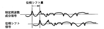
図2は位相シフトの様子の例を示す図である。なお、図2、図3は、2次元の画像データのうち1ラインの信号を例示的に示しているため、1次元の信号が描かれている。両図共に横軸が画像中の位置を示し、縦軸は画像信号の値(例えば輝度値など)を示す。 FIG. 2 is a diagram showing an example of the state of phase shift. 2 and 3 exemplarily show a signal of one line in the two-dimensional image data, a one-dimensional signal is drawn. In both figures, the horizontal axis indicates the position in the image, and the vertical axis indicates the value of the image signal (for example, the luminance value).
透かし信号生成器12に入力された原画像100の特定周波数成分信号の波形を保った状態で、その位相がシフトされている。位相のシフト量によって2次元画像データ内での透かし情報105の埋め込み位置が制御される。透かし信号生成器12は、予め決められたシフト量を利用する。シフト量は、埋め込む透かし情報105の情報量等によってあらかじめ設定され、透かし信号生成器12に与えられるものである。位相がシフトされた特定周波数成分信号に乗算される係数の符号や大きさは、原画像100の複雑度を表すアクティビティ等に応じて決定される。例えば、アクティビティが大きいほど係数は大きく設定される。なお、ビットの値が”1”である場合と”0”である場合とでその係数は異なる。
The phase of the
透かし信号重畳器13は、ディジタル加算器であり、入力された透かし信号101を原画像100に重畳し、埋込済画像106を生成する。透かし信号重畳器13は、ある決められたパターンで透かし信号101の符号(+−)を反転させながら原画像100への埋め込みを行う。例えば、原画像100の各フレームに対して10フレーム毎に透かし信号101の符号を反転させる等の極性変化パターンで重畳を行う。これは検出時に、透かし情報を埋め込んだ画像から、画像信号成分(原画像100による信号成分)と透かし信号101の成分とを分離しやすくするためである。同じ符号(極性)で透かし信号101が重畳されたフレームが同じ期間(第1の期間)に含まれるフレームである。
The watermark signal superimposing unit 13 is a digital adder, and superimposes the input watermark signal 101 on the
なお、周波数成分抽出器11によって抽出された特定周波数成分信号は、複数チャネル存在してもよく、その場合は複数チャネルの特定周波数成分に基づき生成された透かし信号101が、それぞれ透かし信号重畳部13において原画像100に重畳される。
The specific frequency component signal extracted by the frequency component extractor 11 may exist in a plurality of channels. In this case, the watermark signal 101 generated based on the specific frequency components of the plurality of channels is respectively converted into the watermark signal superimposing unit 13. Is superimposed on the
周波数成分抽出器11は、図3(a)に示す埋め込み対象画像信号(原画像100)の特定周波数成分信号を抽出する。図3(b)は抽出された特定周波数成分信号(特定の周波数成分の画像)である。 The frequency component extractor 11 extracts a specific frequency component signal of the embedding target image signal (original image 100) shown in FIG. FIG. 3B is an extracted specific frequency component signal (image of a specific frequency component).
この特定周波数成分信号は、透かし信号生成器12(2つの位相シフタ)によって予め定められた所定のシフト量だけ位相シフトした、2つの異なる位相シフト信号を生成している。次に、生成された位相シフト信号に、透かし情報105の第0ビットまたは第1ビットを表現する係数が乗じられる。例えば、透かし情報105が“0”であれば、位相シフト信号に−1が乗じられ、“1”であれば、位相シフト信号に+1が乗じられる。なお、透かし信号生成器12が2つの位相シフタであるのは、生成する位相シフト信号が2ビットである例を示しているためである。
The specific frequency component signal generates two different phase shift signals that are phase-shifted by a predetermined shift amount determined in advance by the watermark signal generator 12 (two phase shifters). Next, the generated phase shift signal is multiplied by a coefficient representing the 0th bit or the 1st bit of the
図3(c)および(d)は、埋め込む透かし情報105が2ビットの情報(1,1)である場合の位相シフト信号の例を示す図である。2ビットの情報は(0,0)(0,1)(1,0)(1,1)の4通り組み合わせがある。図3(c)に示すように、1ビット目に相当する信号として、特定周波数成分信号を1に相当する+の符号とし、X方向にαだけ位相をシフトした信号を生成する。また、図3(d)に示すように、2ビット目に相当する信号として、特定周波数成分信号を1に相当する+の符号とし、X方向に2αだけ移送をシフトした信号をシフトした信号を生成する。画像の位相は画像の位置に対応するため、位相シフトは画面内の位置の移動を表している。図3(c)および(d)では、位相シフトにより特定周波数成分信号と位相シフト信号1とでは信号の位置が異なり、信号の最も左にあるピークの位置が異なることになる(ピークの位置の違いは、位相がシフトされたことによって生じたものである)。なお、信号と符号の正負の関係や位相シフト量は例であり、種々の変形例であってかまわない。また、位相シフト量を1次元方向のずれとして例示したが、2次元の画面上の位置のずれを示すものである。
FIGS. 3C and 3D are diagrams showing examples of phase shift signals when the
この後、透かし信号重畳器13がビット表現のためのファクタが乗じられた位相シフト信号を原画像100に加算し生成された埋め込み済み画像信号(埋込済画像106)を図3(e)の実線で示す。図3(e)の破線は、重畳される前の埋め込み対象画像信号、図3(c)及び(d)に示す位相シフト信号を示す。
After that, the embedded image signal (embedded image 106) generated by the watermark signal superimposing unit 13 adding the phase shift signal multiplied by the factor for bit representation to the
以上のようにして透かし情報105が埋め込まれた画像信号(以下、「埋込済画像」と記載)106が出力される。
As described above, the image signal (hereinafter referred to as “embedded image”) 106 in which the
以下、記録媒体あるいは伝送媒体を介して入力された入力画像(透かし情報が埋め込まれた画像)から、透かし情報を検出する電子透かし検出システムの第1〜第3の実施形態について図面を参照して説明する。 Hereinafter, first to third embodiments of a digital watermark detection system for detecting watermark information from an input image (an image in which watermark information is embedded) input via a recording medium or a transmission medium will be described with reference to the drawings. explain.
[第1の実施形態]
第1の実施形態の電子透かし検出システムについて説明する。
[First embodiment]
A digital watermark detection system according to the first embodiment will be described.
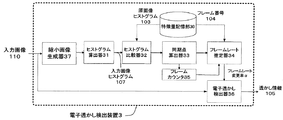
図4は、本実施形態の電子透かし検出装置2の構成を示す図である。電子透かし検出装置2は、特徴量記憶部30、ヒストグラム算出器31、ヒストグラム比較器32、同期点算出器33、フレームレート推定器34、フレームカウンタ35、電子透かし検出器36を有する。
FIG. 4 is a diagram showing a configuration of the digital
電子透かし検出装置2は、入力画像110(電子透かしが埋め込まれたもの)から透かし信号101の成分を分離し、透かし情報105の検出を行う。
The digital
特徴量記憶部30は、原画像の特徴量として、原画像のシーンチェンジ点の前後のヒストグラムである原画像ヒストグラム103と、対応するシーンチェンジ点のフレーム番号104とを記憶している。本実施形態では、輝度に基づくヒストグラムを用いる例について説明する。
The feature amount storage unit 30 stores an
ヒストグラム算出器31は、入力された入力画像110から入力画像ヒストグラム107を算出する。なお、入力画像110の表示時間の前後のフレームでシーンチェンジが起きていると推定される点をあらかじめ推定し、推定された点の前後のフレームのヒストグラムをそれぞれ求めてもよい。ヒストグラム比較器32は、ヒストグラム算出器31が求めた入力画像ヒストグラム107と、特徴量記憶部30にあらかじめ保持した原画像ヒストグラム103とを比較する。
The histogram calculator 31 calculates an
同期点算出器33は、原画像ヒストグラム103と、入力画像ヒストグラム107とを比較し、前記入力画像の点のなかで原画像ヒストグラム103と相関が高い入力画像110の点を同期点として求める。
The synchronization point calculator 33 compares the
その一致の程度に基づき入力画像110のうち原画像ヒストグラム103と同期する点である同期点を求める。前後の各フレーム(若しくは同じシーン内の複数フレームの平均等)の原画像ヒストグラム103と、入力画像110のフレームの入力画像ヒストグラム107とを比較する。
Based on the degree of coincidence, a synchronization point that is a point that is synchronized with the
本実施形態では、原画像のシーンチェンジ点の前後の各フレーム(若しくは同じシーン内の複数フレームの平均等)の原画像ヒストグラム103と、入力画像110の各フレームの入力画像ヒストグラム107とを比較する。次に、両ヒストグラムの比較結果(相関の程度)に基づいて、原画像のシーンチェンジ点と対応する入力画像110のシーンチェンジ点を同期点として求める。詳細な処理については後述する。
In this embodiment, the
フレームカウンタ35は、同期点算出器33が求めた入力画像110の各同期点の間(同期点間隔)に含まれる入力画像110のフレーム数をカウントする。
The frame counter 35 counts the number of frames of the
フレームレート推定器34は、フレーム番号104と、フレームカウンタ35のカウントしたフレームの数とから、原画像100のシーンチェンジ点間隔に含まれるフレームの数と入力画像110の同期点間隔に含まれるフレームの数との変更量を推定する。本実施形態では、変更量としてフレームレートの変更率αを推定する。フレームレートの変更率αは、シーンチェンジ点間隔と同期する同期点間隔に含まれるフレーム数の違いを示す。これは、映写機の回転スピードに個体差があること等に起因する時間的なずれにより、同期するシーンチェンジ点であっても入力画像110と原画像100とで、その間に含まれるフレームの数に違いが生じるためである。なお、変化量としてフレーム数の差分を利用してもよい。
The frame rate estimator 34 calculates the number of frames included in the scene change point interval of the
電子透かし検出器36は、フレームレート推定器34により推定されたフレームレートの変更率αを利用して入力画像110から透かし信号101を分離し、透かし情報105を検出する。詳細な構成及び動作については後述する。
The digital watermark detector 36 separates the watermark signal 101 from the
図5は、電子透かし検出装置2の処理を示すフローチャートである。
FIG. 5 is a flowchart showing the processing of the digital
まず、ヒストグラム算出器31が入力画像ヒストグラム107を算出する(ステップS31)。次に、ヒストグラム比較器32がヒストグラム比較において、原画像のシーンチェンジ点の前後のヒストグラムである原画像ヒストグラム103と、入力画像110の表示時間が前後の入力画像ヒストグラム107とを比較する(ステップS32)。比較結果から、原画像100のシーンチェンジ点と同期する入力画像110の同期点を求める(ステップS33)。同期点とは、その前後のヒストグラムが、原画像のシーンチェンジ点の前後それぞれのヒストグラムと相関が高い点の入力画像のフレーム番号を示す。フレーム番号は、フレームカウンタ35がカウントした同期点間隔に含まれるフレーム数から、同期点算出器33が定める。
First, the histogram calculator 31 calculates the input image histogram 107 (step S31). Next, in the histogram comparison, the histogram comparator 32 compares the
次に、入力画像110と原画像100のフレームレートの変更率αを推定する(ステップS34)。まず、入力画像110の同期点と同期点の間(同期点間隔)に含まれる入力画像110のフレーム数をフレームカウンタ35が測定する。原画像100のシーンチェンジ点とシーンチェンジ点の間(シーンチェンジ点間隔)に含まれるフレーム数を、特徴量記憶部30に記憶されたフレーム番号104から求める。フレーム番号は、あらかじめ特徴量記憶部30に保持されている。あるシーンチェンジ点後の最初のフレームのフレーム番号104を、その次のシーンチェンジ点後の最初のフレームのフレーム番号104から引くことでフレーム数を求めることが出来る。シーンチェンジ点間隔に含まれるフレーム数と、そのシーンチェンジ点間隔と同期する同期点間隔に含まれるフレーム数とから、入力画像110と原画像100とのフレームレートの変更率αを推定する。
Next, the frame rate change rate α between the
次に、推定されたフレームレートを利用して、入力画像110に埋め込まれている透かし情報105を検出し、透かし情報を出力して処理を終了する(ステップS35)。透かし情報105の詳細な検出方法については後述する。
Next, using the estimated frame rate, the
ヒストグラム比較器32が原画像ヒストグラム103と入力画像ヒストグラム107とを比較する方法(ステップS32)、及び同期点算出器33が、比較結果から同期点を求める方法(ステップS33)について、図6〜図9を参照して説明する。
A method in which the histogram comparator 32 compares the
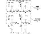
図6〜図8は、原画像ヒストグラム103と入力画像ヒストグラム107とを比較する方法を説明するための図である。それぞれ、(a)は原画像100でのシーンチェンジ点はN(OBn,OAn)である。表示時間がシーチェンジ点Nの前のフレームOBnの原画像ヒストグラム103を示す。また、(b)は表示時間がシーチェンジ点Nの後のフレームOAnの原画像ヒストグラム103を示す。比較を行う入力画像110の点は点M(IBm,IAm)である。(c)は表示時間が点Mの前のフレームIBmの入力画像ヒストグラム107を示す。また、(d)は表示時間が点Mの後のフレームIAmの入力画像ヒストグラム107を示す。なお、本実施形態では、ヒストグラムとして方向ヒストグラムを用いた例について説明する。方向ヒストグラムとは、隣り合う画素間の画素値の勾配を利用したヒストグラムである。それぞれの画素の隣接画素間での輝度の勾配方向及び勾配の大きさを度数とするヒストグラムである。図6〜図8では、上下左右の4つの勾配方向を成分とする例について示す。
6 to 8 are diagrams for explaining a method of comparing the
図6は、シーンチェンジ点Nと点Mの前のヒストグラム同士、及び後のヒストグラム同士で一致の程度を求める例を示す図である。(e)は、フレームOBnの原画像ヒストグラム103と、フレームIBmの入力画像ヒストグラム107とを方向成分ごとに乗算して得た比較結果を示す。(f)は、フレームOAnの原画像ヒストグラム103と、フレームIAmの入力画像ヒストグラム107とを方向成分ごとに乗算して得た比較結果を示す。方向成分毎に乗算するとは、例えば、入力画像ヒストグラム107の上方向の成分の度数と原画像ヒストグラム103の上方向の成分の度数とを乗算することを示す。その他の方向成分に関しても同様に算出する。
FIG. 6 is a diagram illustrating an example in which the degree of coincidence is obtained between the histograms before and after the scene change point N and the point M. (E) shows a comparison result obtained by multiplying the
比較するフレームのヒストグラムの一致の程度が高い場合、乗算結果は大きな値となる。逆に、ヒストグラムの一致の程度が低いと、乗算結果は小さな値となる。シーンチェンジ点はその前後でヒストグラムの差異が大きな箇所である。図6のように点N、点Mの前同士、後同士のヒストグラムの一致の程度が共に高い場合、点Mとシーンチェンジ点Nとは同期する点であると推定することができる。この様に、乗算結果の大小により原画像ヒストグラム103と入力画像ヒストグラム107との一致程度から、同期点を求めることが出来る。
When the degree of matching of the histograms of the frames to be compared is high, the multiplication result is a large value. Conversely, if the degree of matching of the histograms is low, the multiplication result becomes a small value. A scene change point is a place where the difference in histogram is large before and after the scene change point. When the degree of matching between the histograms before and after points N and M is high as shown in FIG. 6, it can be estimated that point M and scene change point N are synchronized. In this way, the synchronization point can be obtained from the degree of coincidence between the
図7は、図6とは異なる方法でヒストグラム同士の一致程度を求める例を示す図である。シーンチェンジ点Nの前と点Mの後とのヒストグラムの一致の程度を求める。また同様に、シーンチェンジ点Nの後と点Mの前とのヒストグラム同士の一致の程度を求める比較を行っている例を示す図である。(e)は、フレームOAnの原画像ヒストグラム103と、フレームIBmの入力画像ヒストグラム107とを方向成分ごとに乗算して得た比較結果を示す。(f)は、フレームOAnの原画像ヒストグラム103と、フレームIBmの入力画像ヒストグラム107とを方向成分ごとに乗算して得た比較結果を示す。
FIG. 7 is a diagram showing an example in which the degree of matching between histograms is obtained by a method different from that in FIG. The degree of matching of the histograms before the scene change point N and after the point M is obtained. Similarly, it is a diagram illustrating an example in which comparison is performed for obtaining the degree of matching between histograms after the scene change point N and before the point M. FIG. (E) shows a comparison result obtained by multiplying the
前述したように、ヒストグラムの一致程度が高いと乗算結果は大きな値となる。図7のように、点N、点Mの前同士、後同士のヒストグラムの一致の程度が共に高い場合、シーンチェンジ点Nの前と点Mの後とのヒストグラムの一致の程度と、シーンチェンジ点Nの後と点Mの前とのヒストグラム同士の一致の程度とが共に低くなる。この場合、点Mはシーンチェンジ点Nと同期するものと推定することが出来る。 As described above, when the degree of matching of the histograms is high, the multiplication result becomes a large value. As shown in FIG. 7, when the degree of matching of the histograms before and after points N and M is high, the degree of matching of histograms before scene change point N and after point M The degree of matching between the histograms after the point N and before the point M is lowered. In this case, it can be estimated that the point M is synchronized with the scene change point N.
上記のように、ヒストグラムを方向成分毎に乗算した結果の大小からシーンチェンジ点と同期する入力画像110の同期点を求めることが出来る。
As described above, the synchronization point of the
図8は、図6図7で示した方法とは異なる方法でヒストグラム同士の一致程度を求める例を示す図である。(e)は、フレームOBnの原画像ヒストグラム103と、フレームIBmの入力画像ヒストグラム107とを方向成分ごとに除算して得た比較結果を示す。(f)は、フレームOAnの原画像ヒストグラム103と、フレームIAmの入力画像ヒストグラム107とを方向成分ごとに除算して得た比較結果を示す。
FIG. 8 is a diagram showing an example in which the degree of coincidence between histograms is obtained by a method different from the method shown in FIG. 6 and FIG. (E) shows a comparison result obtained by dividing the
比較するフレームのヒストグラムの一致の程度が高い程、除算結果は1に近い値となる。逆に、ヒストグラムの一致の程度が低い程、除算結果は1から遠い値となる。図8のように点N、点Mの前同士、後同士のヒストグラムの一致の程度が共に高い場合、各成分の除算結果は1に近い値となることが分かる。この場合、点Mとシーンチェンジ点Nとは同期する点であると推定することができる。この様にして、除算結果から原画像ヒストグラム103と入力画像ヒストグラム107の一致程度を算出することが出来る。なお、比較するヒストグラムが類似していれば、除算結果は1に近い値となると考えられるため、除算結果の統計量(例えば、平均や分散)を用いもよい。その場合、除算結果の平均値が1に近い場合や分散が小さい場合に、比較したヒストグラム同士が類似していると推定することができる。
The higher the degree of matching of the histograms of the frames to be compared, the closer the division result is to 1. Conversely, the lower the degree of matching of histograms, the farther the division result is from 1. As shown in FIG. 8, when the degree of matching between the histograms before and after points N and M is high, it can be seen that the division result of each component is a value close to 1. In this case, it can be estimated that the point M and the scene change point N are synchronized. In this way, the degree of coincidence between the
なお、ここで記載した図6〜図8の算定手法を組み合わせてヒストグラムの一致程度を算出することも考えられる。また、ここでは乗除算を用いてヒストグラム一致程度の算定を行ったが、加減算などの他手法を利用することも可能である。 It is also conceivable to calculate the degree of coincidence of histograms by combining the calculation methods of FIGS. 6 to 8 described here. In this example, multiplication and division are used to calculate the degree of histogram matching, but other methods such as addition and subtraction can also be used.
以上のようにして、原画像ヒストグラム103と入力画像ヒストグラム107とを比較し、ヒストグラムの相関が高いフレーム番号の対を複数求め、同期点を求める。
As described above, the
フレームレート推定器34が、算出された同期点に基づき入力画像110のフレームレートを推定する方法(ステップS34)について、図9を参照して説明する。
A method (step S34) in which the frame rate estimator 34 estimates the frame rate of the
図9は、入力画像110のフレームレートを推定する方法を説明するための図である。図9(a)は、原画像100のフレームの構成を示す。図9(b)は、入力画像110のフレームの構成を示す。矢印は共に表示時間を示す。
FIG. 9 is a diagram for explaining a method for estimating the frame rate of the
原画像100でのシーンチェンジ点はN(OBn,OAn)、N+1(OBn+1,OAn+1)、N+2(OBn+2,OAn+2)である。また、入力画像110の同期点はM(IBm,IAm)、M+1(IBm+1,IAm+1)、M+2(IBm+2,IAm+2)である。同期点(入力画像110でのシーンチェンジ点)は、図6〜図8に示すヒストグラムの比較等によって求める。
The scene change points in the
シーンチェンジ点N(OBn,OAn)は、フレーム番号OBnのフレームと番号OAnのフレームとの間にあるシーンチェンジ点であることを示している。その他の点に関しても同様の表記をしている。 The scene change point N (OBn, OAn) indicates that it is a scene change point between the frame with the frame number OBn and the frame with the number OAn. The same notation is used for other points.
原画像100でのシーンチェンジ点NとN+1との間のシーンチェンジ点間隔O1は、フレーム番号よりOBn+1−OBnフレームである。同様にシーンチェンジ点N+1とN+2との間のシーンチェンジ点間隔O2は、フレーム番号よりOBn+2−OBn+1フレームである。
The scene change point interval O1 between the scene change points N and N + 1 in the
入力画像110の同期点間隔は同期点MとM+1との間の同期点間隔I1は、フレーム番号よりIBm+1−IBmフレームである。同様に同期点M+1とM+2との間の同期点間隔I2は、IBm+2−IBm+1フレームである。
The synchronization point interval I1 between the synchronization points M and M + 1 is an IBm + 1-IBm frame from the frame number. Similarly, the synchronization point interval I2 between the synchronization points M + 1 and M + 2 is IBm + 2−
シーンチェンジ点間隔の比率を算出すると、原画像100ではO2÷O1=(OBn+2−OBn+1)÷(OBn+1−OBn)、入力画像110ではI2÷I1=(IBm+2−IBm+1)÷(IBm+1−IBm)となる。ここで、原画像100でのシーンチェンジ点と入力画像110のシーンチェンジ点が対応するシーンチェンジ点であれば、前述の時間的な攻撃がなされた場合であっても、シーンチェンジ点間隔の比率は殆ど一致する。原画像100と入力画像110とでフレームレートが変化してもシーンチェンジ点間隔の比率は変化せず、シーンチェンジ点間隔の比率はフレームレートには影響しない為である。シーンチェンジ同期を原画像100と入力画像110のシーンチェンジ点間隔の比率を用いることで、より精度良くシーンチェンジ点と同期する点を求めることが出来る。なお、ヒストグラム比較の例で示したヒストグラムの一致程度の結果のみを利用して、原画像100と入力画像110の同期を行うことも可能である。
When the ratio of the scene change point intervals is calculated, in the
図9では、シーンチェンジ点Nと同期点Mとが、シーンチェンジ点N+1と同期点M+1とが、シーンチェンジ点N+2と同期点M+2とが互いに同期する点であるとする。 In FIG. 9, it is assumed that the scene change point N and the synchronization point M are the scene change point N + 1 and the synchronization point M + 1, and the scene change point N + 2 and the synchronization point M + 2 are synchronized with each other.
例えば、原画像100でのシーンチェンジ点間隔O1(OBn+1−OBn)が1000フレームであり、入力画像110のO1と対応する同期点間隔I1(IBm+1−IBm)が1100フレームであるとする。シーンチェンジ点Nと同期点Mとが互いに同期することから、入力画像110のフレームレートの変更率αは、α=1100/1000=1.1であると推定することが出来る。
For example, assume that the scene change point interval O1 (OBn + 1−OBn) in the
図10は、電子透かし検出器36の構成を示す図である。 FIG. 10 is a diagram showing a configuration of the digital watermark detector 36.
電子透かし検出器36は、拡大縮小器27、周波数成分抽出器20、第1直行変換器21、合成器22、第2直行変換器23、累積加算器24、推定器25を有する。
The digital watermark detector 36 includes an enlargement / reduction unit 27, a frequency component extractor 20, a first orthogonal converter 21, a
拡大縮小器27は、電子透かしが埋め込まれた入力画像110の拡大(もしくは縮小)を行う。なお、拡大縮小器27は1倍、周波数成分抽出器20は全ての周波数成分を抽出する場合もある。拡大縮小器27は、電子透かし埋め込み装置1で用いられている埋込拡大縮小器10と同じ拡大縮小率で入力画像110の拡大(もしくは縮小)を行う。
The enlargement / reduction unit 27 enlarges (or reduces) the
周波数成分抽出器20は、拡大縮小器27によって拡大(もしくは縮小)された入力画像110から特定周波数成分を抽出する。周波数成分抽出器20は周波数成分抽出器11と同じ周波数領域のディジタルフィルタ、例えば所定のカットオフ周波数を有するローパスフィルタやハイパスフィルタ、あるいは所定の通過域中心周波数を有するバンドパスフィルタである。
The frequency component extractor 20 extracts a specific frequency component from the
第1直交変換器21は、周波数成分抽出器20によって抽出された特定周波数成分を有する信号に対して直交変換などの直交変換処理をする。同様に、入力画像110に対しても直行変換処理をする。
The first orthogonal transformer 21 performs orthogonal transformation processing such as orthogonal transformation on the signal having the specific frequency component extracted by the frequency component extractor 20. Similarly, an orthogonal conversion process is performed on the
合成器22は、直交変換後の2つの信号を複素合成した信号を生成する。ここで、第1直交変換後の振幅成分は、振幅を調整することにより、位相に比重をおいた複素合成を行っても構わない。
The
第2直交変換器23は、合成器22によって複素合成された後の合成信号に対して直交変換(逆直交変換)を行う。ここでの直交変換は第1直交変換での変換と対になっている必要がある。例えば、第1直交器21がフーリエ変換を行った場合には、第2直交変換器23では逆フーリエ変換を行う。
The second orthogonal transformer 23 performs orthogonal transformation (inverse orthogonal transformation) on the synthesized signal that has been complex-synthesized by the
累積加算器24は、フレームレート推定器34が推定したフレームレート変更率αに基づいて、透かし信号重畳器13が透かし信号101を重畳する際の極性の反転パターンと同期をさせながら極性を調整し、第2直交変換後の信号の累積加算を行う。例えば、埋め込みをする際に、1フレーム毎に透かし信号101の符号を反転させて埋め込みを行った場合には、検出においても、1フレーム毎に符号を反転させながら累積を行う必要がある。また、フレームレートが変更(例えば、α=2[倍])になった場合には、検出時に、極性を2フレーム毎に反転させ、同じ極性の1フレーム分を累積加算することで埋め込みと検出の同期をとる必要がある。詳細については後述する。 The cumulative adder 24 adjusts the polarity based on the frame rate change rate α estimated by the frame rate estimator 34 while synchronizing with the polarity inversion pattern when the watermark signal superimposing device 13 superimposes the watermark signal 101. Then, cumulative addition of signals after the second orthogonal transformation is performed. For example, when embedding is performed by inverting the sign of the watermark signal 101 for each frame, it is necessary to perform accumulation while inverting the code for each frame. Also, when the frame rate is changed (for example, α = 2 [times]), the polarity is reversed every two frames at the time of detection, and embedding and detection are performed by cumulatively adding one frame of the same polarity. Must be synchronized. Details will be described later.
推定器25は、累積加算後の信号(変換後の合成信号)から透かし情報105を推定する。なお、透かし情報105として、ディジタル信号の”1”または”0”が埋め込まれている。
The
電子を透かし検出する方法(電子透かし検出ステップS35)について説明する。 A method for detecting an electronic watermark (electronic watermark detection step S35) will be described.
図11は、電子透かし検出器36が入力画像110から、埋め込まれた透かし情報105を検出する方法を示すフローチャートである。
FIG. 11 is a flowchart showing how the digital watermark detector 36 detects the embedded
まず、拡大縮小器27は入力された入力画像110の拡大(もしくは縮小)を行う(ステップS40)。この際に、埋込拡大縮小器10の拡大縮小率と、同じ倍率で拡大(もしくは縮小)を行う。なお、拡大縮小率が1倍の場合もある。
First, the enlargement / reduction unit 27 enlarges (or reduces) the
次に、周波数成分抽出器20は拡大縮小された入力画像110の特定周波数成分の信号成分を抽出する(ステップS41)。この際に、周波数成分抽出器11が抽出した周波数成分と同じ周波数領域を抽出する。なお、全ての周波数成分を特定周波数成分として抽出する場合もある。 Next, the frequency component extractor 20 extracts a signal component of a specific frequency component of the enlarged / reduced input image 110 (step S41). At this time, the same frequency region as the frequency component extracted by the frequency component extractor 11 is extracted. Note that all frequency components may be extracted as specific frequency components.
次に、第1直行変換器21はステップS41で抽出された信号に対して直交変換などの直交変換処理をする(ステップS42)。 Next, the first orthogonal transformer 21 performs orthogonal transformation processing such as orthogonal transformation on the signal extracted in step S41 (step S42).
なお、ステップS42と同様に、第1直行変換器21は、入力画像110に対しても直交変換などの直交変換処理をする(ステップS47)。 As in step S42, the first orthogonal transformer 21 performs orthogonal transformation processing such as orthogonal transformation on the input image 110 (step S47).
次に、合成器22は直交変換後の2つの信号を複素合成する(ステップS43)。ここで、第1直交変換後の振幅成分は、振幅を調整し位相に比重をおく複素合成を行っても構わない。
Next, the
第2直行変換器23は、複素合成後の合成信号に対して直交変換(逆直交変換)を行う(ステップS44)。ここで行う直交変換は、第1直交変換器の行う変換と対になっている必要がある。 The second orthogonal transformer 23 performs orthogonal transformation (inverse orthogonal transformation) on the composite signal after complex synthesis (step S44). The orthogonal transformation performed here needs to be paired with the transformation performed by the first orthogonal transformer.
次に、累積加算器24は第2直行変換後の信号の累積加算を行う(ステップS45)。累積加算は、フレームレート推定器34が推定したフレームレート変更率αに基づき、透かし信号重畳器13が透かし信号101を埋め込んだ際と、同期した時系列的なパターンで極性を反転させながら行われる。時系列的なパターンの同期を行う際の詳細な説明は後述する。 Next, the cumulative adder 24 performs cumulative addition of the signal after the second orthogonal conversion (step S45). The cumulative addition is performed based on the frame rate change rate α estimated by the frame rate estimator 34, while inverting the polarity in a synchronized time series pattern when the watermark signal superimposing unit 13 embeds the watermark signal 101. . A detailed description of synchronization of time-series patterns will be described later.
次に、透かし情報105を推定し、出力する(ステップS45)。
Next, the
ステップS45で透かし情報105を推定する方法について図2、図12を用いて説明する。
A method for estimating the
図2に示すように、合成器22によって複素合成された後の合成信号の位相をシフトさせながら、元の位相シフトしていない変換後の合成信号との相関を求める。なお、2つの画像信号間の相関(類似度)を計算する手法として、位相限定相関手法等を利用する。
As shown in FIG. 2, while shifting the phase of the synthesized signal after the complex synthesis by the
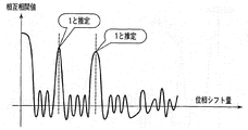
図12は、相互相関値と位相シフト量との関係を示す図である。図10に示すように、ある位相シフト量の位置に相互相関値のピークが現れる。このピークの極性(正・負)が透かし情報105を表す。推定器25は、位相シフト量を連続的あるいは段階的に制御し、それに伴って出力される相互相関値のピークを探索し、探索されたピークの極性から透かし情報105を推定して検出する。相互相関値のピークは、透かし情報105に応じて正・負のいずれかの値をとる。図10では、正の場合は透かし情報105は”1”、負の場合は透かし情報105は”0”と判定される。
FIG. 12 is a diagram illustrating the relationship between the cross-correlation value and the phase shift amount. As shown in FIG. 10, the peak of the cross-correlation value appears at a certain phase shift amount position. The polarity (positive / negative) of this peak represents the
以上のように、入力画像110から特定周波数成分信号を抽出し、この特定周波数成分信号と埋込済画像106の画像信号との位相限定相関の相関結果から透かし情報105を検出する。
As described above, the specific frequency component signal is extracted from the
累積加算器24が、累積加算をする(ステップS44)際にパターンの同期を行う方法を説明する。 A method for synchronizing the patterns when the cumulative adder 24 performs cumulative addition (step S44) will be described.
図13は、累積加算器24が第2直交変換後の信号を累積加算する方法を説明するための図である。図13(a)は、原画像100のフレームの構成を示す図である。図13(b)は入力画像110のフレームの構成を示す図である。両図共に、矢印は表示時間を示す。破線で結ばれたシーンチェンジ点と同期点とは互いに同期する点である。
FIG. 13 is a diagram for explaining a method in which the cumulative adder 24 cumulatively adds the signals after the second orthogonal transformation. FIG. 13A is a diagram illustrating a frame configuration of the
原画像100のそれぞれの期間は透かし信号101を重畳した際の極性の反転パターンであり、同じ期間内のフレームは同じ極性で透かし信号101が重畳されている。第1期間に含まれるフレームの数がAフレームである。同様に、第2期間がBフレームであり、第3期間がCフレームである。
Each period of the
フレームレート推定器34が推定したフレームレート変更率はαである。入力画像110の第1期間(原画像100の第1期間と同期する期間)に含まれるフレームの数はαAフレーム、第2期間はαBフレーム、第3期間はαCフレームとなる。そのため、それぞれの期間はその期間と同期する原画像の期間内に含まれるフレームの数と同じ枚数のパターンおよび同じ極性で信号を重畳する必要がある。 The frame rate change rate estimated by the frame rate estimator 34 is α. The number of frames included in the first period of the input image 110 (period synchronized with the first period of the original image 100) is αA frame, the second period is αB frame, and the third period is αC frame. Therefore, in each period, it is necessary to superimpose signals with the same number of patterns and the same polarity as the number of frames included in the period of the original image synchronized with the period.
α>1の場合には、期間に含まれる所定のフレームの信号を重畳しない等によって原画像100の同期する期間に含まれるフレームと同じ数の信号を重畳する。また、α<1の場合には、期間に含まれる所定のフレームの信号を複数回累積させる等によって原画像100の同期する期間に含まれるフレームと同じ数の信号を重畳する。
When α> 1, the same number of signals as the frames included in the synchronized period of the
また、重畳するフレーム数を同じ数にする他に、変更率αから、入力画像110での反転パターンを推定し、第1期間に含まれるフレームは、原画像に透かし信号101を重畳した際の反転パターンと同じ反転パターンでαAフレーム分重畳し、パターンを同期する手法であっても良い。
In addition to the same number of frames to be superimposed, the inversion pattern in the
いずれの手法であっても、原画像100と入力画像110との時間的なずれによる埋込と検出の累積パターン誤差が蓄積しないようにすることができる。
In any method, it is possible to prevent accumulation of embedding and detection accumulated pattern errors due to a time lag between the
以上の様に、透かし信号重畳器13が透かし信号101重畳する際の極性の反転パターンと、累積加算器24が第2直交変換後の信号を累積加算する際の極性の反転パターンとを同期する。 As described above, the polarity inversion pattern when the watermark signal superimposing unit 13 superimposes the watermark signal 101 is synchronized with the polarity inversion pattern when the cumulative adder 24 cumulatively adds the signals after the second orthogonal transformation. .
それによって、映写機の回転スピードに個体差があること等に起因する時間的なずれによりフレームレートが変更された場合であっても、安定して透かし情報の検出をすることができる。 Thereby, even when the frame rate is changed due to a time lag caused by individual differences in the rotation speed of the projector, watermark information can be detected stably.
電子透かし検出装置2が、2ビットの透かし情報105を検出する動作例を、図14〜図16を用いて説明する。簡単のため、拡大縮小器27が行う拡大縮小率は1倍であるとする。
An operation example in which the digital
図14は、第1の実施形態の電子透かし検出装置の動作を説明する図である。2次元の画像データのうち1ラインの信号を例示的に示しているため、1次元の信号が描かれている。 FIG. 14 is a diagram for explaining the operation of the digital watermark detection apparatus according to the first embodiment. Since one line of the signal of the two-dimensional image data is exemplarily shown, the one-dimensional signal is drawn.
入力画像110から透かし情報105を検出する場合、周波数成分抽出器20は、図14(a)の入力画像信号から、図14(b)の特定周波数成分信号を抽出する。図14(c)(d)は、特定周波数成分信号を所定のシフト量だけ位相シフトさせた位相シフト信号である。入力画像信号と位相シフト信号の相関値が求められ、その相関値のピークから透かし情報105が判定される。例えば、相関値のピークが正であれば、透かし情報105は+1(“1”)と判定され、相関値のピークが負であれば、透かし情報105は−1(“0”)と判定される。なお、入力画像110に対してスケーリング(拡大/縮小)が行われていない場合、入力画像信号は、透かし情報を埋め込んだ際のシフト量(例えば、図3(c)(d)に示すシフト量)と同じシフト量の位置に、相関値のピークが生じる。埋込情報推定器25が、位相シフト量を制御しながら相関値のピークを検出する。そのピーク位置から透かし情報105を推定する。
When the
図15は、透かし情報105が(1,1)の場合の相関値のピーク探索と透かし情報検出の動作を示す図である。図15のように相関値の正のピークが原点(位相シフト量が零の点)以外に2箇所存在することにより、透かし情報105である(1,1)が検出される。
FIG. 15 shows the correlation value peak search and watermark information detection operations when the
図16は、透かし情報105が(1,−1)の場合の相関値のピーク探索と透かし情報検出の動作を示す図である。図16のように相関値の正のピークが原点の近いところに存在し、負のピークが原点から正のピークより遠いところに存在することにより、透かし情報105である(1,−1)が検出される。
FIG. 16 shows the correlation value peak search and watermark information detection operations when the
なお、特定周波数成分信号を原画像100に加算して埋込済画像106を作成する際に、ライン毎、複数ライン毎、フィールド毎、複数フィールド毎、フレーム毎および複数フレーム毎のいずれか、あるいはこれらの適宜の組み合わせで位相シフト信号の極性を反転する方式や、位相シフト量を変更する方式を用いても良い。
In addition, when the embedded image 106 is created by adding the specific frequency component signal to the
本実施形態では、電子透かし検出装置2が検出を行う前(コンテンツ作成時等)に原画像100の特徴量(原画像ヒストグラム103、フレーム番号104)を、あらかじめ求めておき、特徴量記憶部30に保持している例について説明した。該当する特徴量が特徴量記憶部30に記憶されていない場合に、検出時に原画像100を電子透かし検出装置2に入力し、原画像100から電子透かし検出装置2が特徴量を求める構成であってもよい。その場合、特徴量として原画像100から原画像ヒストグラム103の算出を行い、シーンチェンジ点の前後のフレームの特徴量を算出する。また、原画像100のシーンチェンジ点の前後のフレームのフレーム番号も算出する必要がある。
In this embodiment, before the digital
また、比較を行うヒストグラムはシーンチェンジの前後の1枚のフレームである例について示したが、シーンチェンジの前後それぞれ複数枚のフレームのヒストグラムを求め、その平均について比較を行ってもかまわない。 In addition, although the example of the histogram for comparison is one frame before and after the scene change, a histogram of a plurality of frames before and after the scene change may be obtained and the average may be compared.
また、ヒストグラム算出器31、ヒストグラム比較器32が用いる画像のヒストグラムとして、輝度ヒストグラム、方向ヒストグラム、エッジヒストグラム等を利用することが出来る。これらのヒストグラムのうちいずれかのヒストグラムを用いる場合、また、複数のヒストグラムを用いる場合も考えられる。 Further, as a histogram of an image used by the histogram calculator 31 and the histogram comparator 32, a luminance histogram, a direction histogram, an edge histogram, or the like can be used. When any one of these histograms is used, a plurality of histograms may be used.
輝度ヒストグラムとは、画像中にどの輝度値をもった画素がどれだけ存在しているかの分布を示すヒストグラムである。 The luminance histogram is a histogram showing the distribution of how many pixels having which luminance value exist in the image.
エッジヒストグラムとは、エッジの方向を利用したヒストグラムである。画像中の各画素におけるエッジの方向と強度を算出する。エッジの方向を複数の階級に分割し、同じ階級に割り当てられた画素数をその階級の度数となるようにして求められたヒストグラムである。 An edge histogram is a histogram that uses the direction of an edge. The edge direction and intensity at each pixel in the image are calculated. It is a histogram obtained by dividing the direction of the edge into a plurality of classes and making the number of pixels assigned to the same class become the frequency of the class.
想定しているアプリケーション(適用するシステム)に応じて、それらのうち最適なヒストグラムを適宜利用することができる。例えば、シーンチェンジ点以外で大きな輝度変化が想定される場合には、方向ヒストグラムやエッジヒストグラムが有効であると考えられる。また、シーンチェンジ点以外大きな輝度変化が想定されない場合には、輝度ヒストグラムの利用が有効であると考えられる。 Depending on the assumed application (applied system), an optimal histogram can be used as appropriate. For example, when a large luminance change is assumed at a point other than the scene change point, the direction histogram and the edge histogram are considered to be effective. In addition, when a large luminance change other than the scene change point is not expected, it is considered effective to use the luminance histogram.
[第2の実施形態]
第2の実施形態の電子透かし検出システムについて説明する。本実施形態の電子透かし検出装置は、電子透かしが埋め込まれた入力画像110を縮小して得た画像に対してヒストグラム算出処理を行う。
[Second Embodiment]
A digital watermark detection system according to the second embodiment will be described. The digital watermark detection apparatus of this embodiment performs a histogram calculation process on an image obtained by reducing the
図17は、本実施形態の電子透かし検出装置3の構成を示す図である。 FIG. 17 is a diagram showing a configuration of the digital watermark detection apparatus 3 of the present embodiment.
本実施形態の電子透かし検出装置3は、図2の電子透かし検出装置2と比較して縮小画像生成器37をさらに有する。
The digital watermark detection apparatus 3 of the present embodiment further includes a reduced image generator 37 as compared with the digital
縮小画像生成器37は、入力画像110を縮小する。
The reduced image generator 37 reduces the
ヒストグラム算出器31は、縮小された入力画像110からヒストグラムを算出する。
The histogram calculator 31 calculates a histogram from the reduced
なお、縮小画像生成器37による縮小画像の作成手法として、ディジタルフィルタを利用する場合や、画像を水平方向や垂直方向に間引く場合など様々考えられるが、いずれの方法であっても良い。 Various methods can be considered as a method of creating a reduced image by the reduced image generator 37, such as using a digital filter or thinning out an image in the horizontal direction or the vertical direction.
本実施形態の電子透かし検出装置によれば、ヒストグラム算出時の処理量を削減することが可能となる。また、ヒストグラムの算出は画像の画面全体に対して行うのではなく、画面中央部に対して行うことも考えられる。この様にすることで、処理量の削減だけでなく、フレームレート推定性能の向上が見込まれる。入力画像110の画面中央部には原画像100が多く含まれる可能性が高いためである。例えば、テレビ画面の撮影画像が検出システムに入力された場合には、撮影画面にはテレビフレームといった原画像100以外の成分も撮影されている可能性があるが、画面中央部はこの種の原画像100以外の成分が撮影される可能性が少なく、フレームレート推定がより正確に行うことができる。
According to the digital watermark detection apparatus of the present embodiment, it is possible to reduce the amount of processing when calculating a histogram. In addition, the calculation of the histogram may be performed not on the entire screen of the image but on the center of the screen. In this way, not only the amount of processing is reduced but also the frame rate estimation performance is expected to be improved. This is because the
[第3の実施形態]
第3の実施形態の電子透かし検出システムについて説明する。本実施形態の電子透かし検出システムは、ヒストグラム算出とヒストグラム比較の処理を、入力画像110を分割した画像に対して行う例である。
[Third embodiment]
A digital watermark detection system according to a third embodiment will be described. The digital watermark detection system of this embodiment is an example in which histogram calculation and histogram comparison processing are performed on an image obtained by dividing the
図18は、本実施形態の電子透かし検出装置4の構成を示す図である。 FIG. 18 is a diagram showing a configuration of the digital watermark detection apparatus 4 of the present embodiment.
電子透かし検出装置4は、図2の電子透かし検出装置2と比較して分割画像生成器38をさらに有する。
The digital watermark detection apparatus 4 further includes a divided image generator 38 as compared with the digital
電子透かし検出装置4の特徴量記憶部30には、あらかじめ原画像100を所定の数に分割した画像それぞれの分割画像のヒストグラム(以下、原画像分割ヒストグラムと記載)108を保持している。
The feature amount storage unit 30 of the digital watermark detection apparatus 4 holds a histogram (hereinafter, referred to as an original image division histogram) 108 of divided images of images obtained by dividing the
分割画像生成部38は、原画像分割ヒストグラム108を生成する際に原画像100を分割した分割領域と同じ大きさ、数に入力画像110を分割する。
The divided image generation unit 38 divides the
ヒストグラム算出器31は、入力画像110の分割された画像のヒストグラムを算出する。
The histogram calculator 31 calculates a histogram of the divided image of the
ヒストグラム比較器32は、入力画像110の分割された画像のヒストグラムと原画像分割ヒストグラム108との比較を行う。
The histogram comparator 32 compares the histogram of the divided image of the
同期点算出器33は、分割された画像毎のヒストグラムの比較結果に基づいてシーンチェンジ点と同期する点を求める。ここでは2分割の例であるが、分割数を増やすことも考えられる。また、分割は、入力画像を水平方向に分割する場合、垂直方向に分割する場合、また水平垂直方向に分割する場合と様々考えられる。 The synchronization point calculator 33 obtains a point synchronized with the scene change point based on the comparison result of the histograms for each divided image. Although an example of two divisions is shown here, it is possible to increase the number of divisions. Further, there are various types of divisions such as dividing the input image in the horizontal direction, dividing in the vertical direction, and dividing in the horizontal and vertical direction.
この様に分割した画像同士を利用することにより、ヒストグラムやシーンチェンジ点間隔比率がより正確に算出できると期待できる。なお、電子透かし検出システムが想定しているアプリケーションにより最適な分割数は変化すると考えられる。大きな幾何変形攻撃が想定される場合には、分割数の増加は性能低下につながると考えられるが、大きな幾何変形が想定されない場合には、分割数の増加により性能が向上すると考えられる。 It can be expected that the histogram and the scene change point interval ratio can be calculated more accurately by using the images divided in this way. Note that the optimal number of divisions may vary depending on the application assumed by the digital watermark detection system. When a large geometric deformation attack is assumed, an increase in the number of divisions is considered to lead to a decrease in performance. However, when a large geometric deformation is not assumed, it is considered that the performance is improved by an increase in the number of divisions.
上記の各実施形態の画像処理装置は、例えば、汎用のコンピュータ装置を基本ハードウェアとして用いることでも実現することが可能である。また、プログラムとしてインストール可能な形式又は実行可能な形式のファイルでCD-ROM、CD−R、DVD等のコンピュータで読み取り可能な記録媒体に記録し提供しても、ROM等に予め組み込んで提供してもよい。実行されるプログラムは、上述した各機能を含むモジュール構成となっている。 The image processing apparatus according to each of the embodiments described above can be realized by using, for example, a general-purpose computer apparatus as basic hardware. In addition, even if a program-installable or executable format file is recorded and provided on a computer-readable recording medium such as a CD-ROM, CD-R, or DVD, it is provided by being incorporated in advance in a ROM or the like. May be. The program to be executed has a module configuration including each function described above.
100・・・原画像
110・・・入力画像
101・・・透かし信号
103・・・原画像ヒストグラム
107・・・入力画像ヒストグラム
108・・・原画像分割ヒストグラム
104・・・フレーム番号
105・・・透かし情報
106・・・埋込済画像
1・・・電子透かし埋め込み装置
10・・・埋込拡大縮小器
11・・・周波数成分抽出器
12・・・透かし信号生成器
13・・・透かし重畳器
2,3,4・・・電子透かし検出装置
30・・・特徴量記憶部
31・・・ヒストグラム算出器
32・・・ヒストグラム比較器
33・・・同期点算出器
34・・・フレームレート推定器
35・・・フレームカウンタ
36・・・電子透かし検出器
37・・・縮小画像生成器
38・・・分割画像生成器
20・・・周波数成分抽出器
21・・・第1直交変換器
22・・・合成器
23・・・第2直交変換器
24・・・累積加算器
25・・・推定器
27・・・拡大縮小器
100 ...
DESCRIPTION OF
2, 3, 4 ... Digital watermark detection device
30 ... Feature value storage unit 31 ... Histogram calculator 32 ... Histogram comparator 33 ... Synchronization point calculator 34 ... Frame rate estimator 35 ... Frame counter 36 ... Digital watermark Detector 37 ... Reduced image generator 38 ... Split image generator
20 ... frequency component extractor 21 ... first
Claims (10)
前記入力画像のフレームのヒストグラムを算出するヒストグラム算出手段と、
前記透かし情報を埋め込む前の画像である原画像の複数のシーンチェンジ点のそれぞれの前後のフレームに関するヒストグラムと、前記入力画像の表示時間の前後のフレームに関するヒストグラムとの相関の高さを比較し、前記原画像の複数のシーンチェンジ点のそれぞれとの相関が所定の基準より高い前記入力画像の同期点を求める同期点算出手段と、
前記シーンチェンジ点の間に含まれる前記原画像のフレーム数と、前記同期点の間に含まれる前記入力画像のフレーム数との変更量を推定する推定手段と、
前記原画像に前記透かし情報を埋め込む際の極性の時系列的な変化パターンを示す極性変化パターンの第1の期間と対応する、前記入力画像の第2の期間を前記変更量に基づき推定し、前記第2の期間に含まれるフレームの信号を、前記第1の期間と同じ極性で累積加算することで得られた信号から前記透かし情報を検出する検出手段と、
を備えたことを特徴とする電子透かし検出装置。 In a digital watermark detection apparatus for detecting watermark information embedded in an input image,
Histogram calculation means for calculating a histogram of a frame of the input image;
Comparing the histogram of the frames before and after each of a plurality of scene change points of the original image, which is the image before embedding the watermark information, with the histogram of the frames before and after the display time of the input image, Synchronization point calculating means for obtaining a synchronization point of the input image having a correlation with each of a plurality of scene change points of the original image higher than a predetermined reference;
Estimating means for estimating an amount of change between the number of frames of the original image included between the scene change points and the number of frames of the input image included between the synchronization points;
Estimating a second period of the input image corresponding to a first period of a polarity change pattern indicating a time-series change pattern of polarity when embedding the watermark information in the original image based on the change amount; Detecting means for detecting the watermark information from a signal obtained by cumulatively adding the signals of the frames included in the second period with the same polarity as the first period;
An electronic watermark detection apparatus comprising:
前記検出手段は、前記極性変化パターンに前記変更率を乗じたパターンと、前記同期点算出手段が求めた前記同期点とから、前記第2期間を推定することを特徴とする請求項1記載の電子透かし検出装置。 The estimation means obtains a change rate between the number of frames of the original image included between the scene change points and the number of frames of the input image included between the synchronization points as the change amount,
The said detection means estimates the said 2nd period from the pattern which multiplied the said change rate to the said polarity change pattern, and the said synchronization point which the said synchronization point calculation means calculated | required. Digital watermark detection device.
前記同期点算出手段は、同様に分割された前記原画像のヒストグラムと前記入力画像のヒストグラムとを比較する、
ことを特徴とする請求項1乃至4のいずれか1項に記載の電子透かし検出装置。 The histogram calculation means divides the input image into a plurality of images,
The synchronization point calculation means compares the histogram of the original image and the histogram of the input image that are similarly divided,
The digital watermark detection apparatus according to claim 1, wherein the digital watermark detection apparatus is a digital watermark detection apparatus.
前記入力画像から特定周波数成分信号を抽出する抽出手段と、
前記特定周波数成分信号及び前記入力画像に対して第1の直交変換を行い、第1の直交変換像を求める第1直交変換手段と、
前記特定周波数成分信号と前記入力画像のそれぞれの前記直交変換像を合成し合成画像を生成する合成手段と、
前記合成画像に前記第1の直交変換と対になる第2の直交変換を行い、第2の直交変換像を求める第2直交変換手段と、
を備え、
前記第2の直交変換像を前記フレームの信号として累積加算した信号から、前記透かし情報を推定することを特徴とする請求項1乃至7のいずれか1項記載の電子透かし検出装置。 The detection means includes
Extracting means for extracting a specific frequency component signal from the input image;
A first orthogonal transform unit for performing a first orthogonal transform on the specific frequency component signal and the input image to obtain a first orthogonal transform image;
A combining unit that combines the orthogonal transform images of the specific frequency component signal and the input image to generate a combined image;
A second orthogonal transformation means for performing a second orthogonal transformation paired with the first orthogonal transformation on the composite image to obtain a second orthogonal transformation image;
With
8. The digital watermark detection apparatus according to claim 1, wherein the watermark information is estimated from a signal obtained by cumulatively adding the second orthogonal transform image as a signal of the frame.
入力画像に埋め込まれている透かし情報を検出する電子透かし検出装置において、
前記入力画像のフレームのヒストグラムを算出するヒストグラム算出ステップと、
前記透かし情報を埋め込む前の画像である原画像の複数のシーンチェンジ点のそれぞれの前後のフレームに関するヒストグラムと、前記入力画像の表示時間の前後のフレームに関するヒストグラムとの相関の高さを比較し、前記原画像の複数のシーンチェンジ点のそれぞれとの相関が所定の基準より高い前記入力画像の同期点を求める同期点算出ステップと、
前記シーンチェンジ点の間に含まれる前記原画像のフレーム数と、前記同期点の間に含まれる前記入力画像のフレーム数との変更量を推定する推定ステップと、
前記原画像に前記透かし情報を埋め込む際の極性の時系列的な変化パターンを示す極性変化パターンの第1の期間と対応する、前記入力画像の第2の期間を前記変更量に基づき推定し、前記第2の期間に含まれるフレームの信号を、前記第1の期間と同じ極性で累積加算することで得られた信号から前記透かし情報を検出する検出ステップと、
を備えたことを特徴とする電子透かし検出方法。 In a digital watermark detection method for detecting watermark information embedded in an input image,
In a digital watermark detection apparatus for detecting watermark information embedded in an input image,
A histogram calculating step for calculating a histogram of a frame of the input image;
Comparing the histogram of the frames before and after each of a plurality of scene change points of the original image, which is the image before embedding the watermark information, with the histogram of the frames before and after the display time of the input image, A synchronization point calculating step for obtaining a synchronization point of the input image whose correlation with each of the plurality of scene change points of the original image is higher than a predetermined reference;
An estimation step for estimating a change amount between the number of frames of the original image included between the scene change points and the number of frames of the input image included between the synchronization points;
Estimating a second period of the input image corresponding to a first period of a polarity change pattern indicating a time-series change pattern of polarity when embedding the watermark information in the original image based on the change amount; A detection step of detecting the watermark information from a signal obtained by cumulatively adding signals of frames included in the second period with the same polarity as the first period;
An electronic watermark detection method comprising:
前記入力画像のフレームのヒストグラムを算出するヒストグラム算出機能と、
前記透かし情報を埋め込む前の画像である原画像の複数のシーンチェンジ点のそれぞれの前後のフレームに関するヒストグラムと、前記入力画像の表示時間の前後のフレームに関するヒストグラムとの相関の高さを比較し、前記原画像の複数のシーンチェンジ点のそれぞれとの相関が所定の基準より高い前記入力画像の同期点を求める同期点算出機能と、
前記シーンチェンジ点の間に含まれる前記原画像のフレーム数と、前記同期点の間に含まれる前記入力画像のフレーム数との変更量を推定する推定機能と、
前記原画像に前記透かし情報を埋め込む際の極性の時系列的な変化パターンを示す極性変化パターンの第1の期間と対応する、前記入力画像の第2の期間を前記変更量に基づき推定し、前記第2の期間に含まれるフレームの信号を、前記第1の期間と同じ極性で累積加算することで得られた信号から前記透かし情報を検出する検出機能と、
をコンピュータに実現させることを特徴とする電子透かし検出プログラム。 In a digital watermark detection program for detecting watermark information embedded in an input image,
A histogram calculation function for calculating a histogram of a frame of the input image;
Comparing the histogram of the frames before and after each of a plurality of scene change points of the original image, which is the image before embedding the watermark information, with the histogram of the frames before and after the display time of the input image, A synchronization point calculation function for obtaining a synchronization point of the input image whose correlation with each of a plurality of scene change points of the original image is higher than a predetermined reference;
An estimation function for estimating the amount of change between the number of frames of the original image included between the scene change points and the number of frames of the input image included between the synchronization points;
Estimating a second period of the input image corresponding to a first period of a polarity change pattern indicating a time-series change pattern of polarity when embedding the watermark information in the original image based on the change amount; A detection function for detecting the watermark information from a signal obtained by cumulatively adding the signals of the frames included in the second period with the same polarity as the first period;
An electronic watermark detection program characterized by causing a computer to realize the above.
Priority Applications (1)
| Application Number | Priority Date | Filing Date | Title |
|---|---|---|---|
| JP2008206293A JP4691147B2 (en) | 2008-08-08 | 2008-08-08 | Digital watermark detection apparatus, method and program |
Applications Claiming Priority (1)
| Application Number | Priority Date | Filing Date | Title |
|---|---|---|---|
| JP2008206293A JP4691147B2 (en) | 2008-08-08 | 2008-08-08 | Digital watermark detection apparatus, method and program |
Publications (2)
| Publication Number | Publication Date |
|---|---|
| JP2010045453A true JP2010045453A (en) | 2010-02-25 |
| JP4691147B2 JP4691147B2 (en) | 2011-06-01 |
Family
ID=42016501
Family Applications (1)
| Application Number | Title | Priority Date | Filing Date |
|---|---|---|---|
| JP2008206293A Expired - Fee Related JP4691147B2 (en) | 2008-08-08 | 2008-08-08 | Digital watermark detection apparatus, method and program |
Country Status (1)
| Country | Link |
|---|---|
| JP (1) | JP4691147B2 (en) |
Cited By (1)
| Publication number | Priority date | Publication date | Assignee | Title |
|---|---|---|---|---|
| CN114885071A (en) * | 2022-04-24 | 2022-08-09 | 河南职业技术学院 | Equipment production data safe transmission method based on artificial intelligence |
Citations (4)
| Publication number | Priority date | Publication date | Assignee | Title |
|---|---|---|---|---|
| WO2005079072A1 (en) * | 2004-02-17 | 2005-08-25 | Mitsubishi Denki Kabushiki Kaisha | Electronic watermarking method, electronic watermark detecting method, apparatus and program |
| JP2005252491A (en) * | 2004-03-02 | 2005-09-15 | Toshiba Corp | Electronic watermark detecting apparatus and method thereof |
| JP2006295605A (en) * | 2005-04-12 | 2006-10-26 | Mitsubishi Electric Corp | Method and apparatus for recovering time synchronization for detecting moving picture electronic watermark |
| WO2007102403A1 (en) * | 2006-03-07 | 2007-09-13 | Nippon Telegraph And Telephone Corporation | Electronic watermark embedding method, device, and program, and electronic watermark detecting method, device, and program |
-
2008
- 2008-08-08 JP JP2008206293A patent/JP4691147B2/en not_active Expired - Fee Related
Patent Citations (4)
| Publication number | Priority date | Publication date | Assignee | Title |
|---|---|---|---|---|
| WO2005079072A1 (en) * | 2004-02-17 | 2005-08-25 | Mitsubishi Denki Kabushiki Kaisha | Electronic watermarking method, electronic watermark detecting method, apparatus and program |
| JP2005252491A (en) * | 2004-03-02 | 2005-09-15 | Toshiba Corp | Electronic watermark detecting apparatus and method thereof |
| JP2006295605A (en) * | 2005-04-12 | 2006-10-26 | Mitsubishi Electric Corp | Method and apparatus for recovering time synchronization for detecting moving picture electronic watermark |
| WO2007102403A1 (en) * | 2006-03-07 | 2007-09-13 | Nippon Telegraph And Telephone Corporation | Electronic watermark embedding method, device, and program, and electronic watermark detecting method, device, and program |
Cited By (2)
| Publication number | Priority date | Publication date | Assignee | Title |
|---|---|---|---|---|
| CN114885071A (en) * | 2022-04-24 | 2022-08-09 | 河南职业技术学院 | Equipment production data safe transmission method based on artificial intelligence |
| CN114885071B (en) * | 2022-04-24 | 2023-09-22 | 河南职业技术学院 | Equipment production data safety transmission method based on artificial intelligence |
Also Published As
| Publication number | Publication date |
|---|---|
| JP4691147B2 (en) | 2011-06-01 |
Similar Documents
| Publication | Publication Date | Title |
|---|---|---|
| KR100841848B1 (en) | Electronic watermark detecting method, apparatus and recording medium for recording program | |
| JP4519678B2 (en) | Digital watermark detection method and apparatus, digital watermark embedding method and apparatus | |
| US8218812B2 (en) | Digital watermark embedding device and method, and digital watermark detection device and method | |
| US8351643B2 (en) | Media fingerprints that reliably correspond to media content | |
| JP4118279B2 (en) | Digital watermark detection apparatus and method | |
| CN100380960C (en) | Watermark embedding and detection of a motion image signal | |
| JP4343179B2 (en) | Digital watermark detection method and apparatus | |
| EP1215625A2 (en) | Method and system for embedding message data in a digital image sequence | |
| JP4901678B2 (en) | Digital watermark embedding device and digital watermark detection device | |
| EP1286306A2 (en) | Data processing apparatus and method of processing data | |
| US20080273744A1 (en) | Digital watermarking method and apparatus | |
| JP2009100296A (en) | Electronic watermark embedding apparatus, electronic watermark detection device, methods thereof, and programs thereof | |
| JP4691147B2 (en) | Digital watermark detection apparatus, method and program | |
| US10460414B2 (en) | Digital watermark information detecting device and digital watermark information detecting method | |
| van Leest et al. | On digital cinema and watermarking | |
| JP2010141591A (en) | Digital watermark embedding method and device, and digital watermark detecting method and device | |
| JP2009290828A (en) | Image processor, and image processing method | |
| KR101220420B1 (en) | Hybrid video forensic watermarking system | |
| EP1286305A2 (en) | Data processing apparatus | |
| JP3919758B2 (en) | Digital watermark detection apparatus and method | |
| KR20090099844A (en) | Apparatus for watermarking based on local auto-correlation function and method therefor | |
| JP4563857B2 (en) | Time synchronization recovery method and apparatus for digital watermark detection for moving images | |
| CN113497981A (en) | Data processing method, device and equipment | |
| JPH11187246A (en) | Information superimposition processing method, superimposed information decoding method, and information superimposing processor and superimposed information decoding device thereof |
Legal Events
| Date | Code | Title | Description |
|---|---|---|---|
| A977 | Report on retrieval |
Free format text: JAPANESE INTERMEDIATE CODE: A971007 Effective date: 20101026 |
|
| A131 | Notification of reasons for refusal |
Free format text: JAPANESE INTERMEDIATE CODE: A131 Effective date: 20101109 |
|
| A521 | Written amendment |
Free format text: JAPANESE INTERMEDIATE CODE: A523 Effective date: 20101122 |
|
| TRDD | Decision of grant or rejection written | ||
| A01 | Written decision to grant a patent or to grant a registration (utility model) |
Free format text: JAPANESE INTERMEDIATE CODE: A01 Effective date: 20110125 |
|
| A01 | Written decision to grant a patent or to grant a registration (utility model) |
Free format text: JAPANESE INTERMEDIATE CODE: A01 |
|
| A61 | First payment of annual fees (during grant procedure) |
Free format text: JAPANESE INTERMEDIATE CODE: A61 Effective date: 20110218 |
|
| FPAY | Renewal fee payment (event date is renewal date of database) |
Free format text: PAYMENT UNTIL: 20140225 Year of fee payment: 3 |
|
| LAPS | Cancellation because of no payment of annual fees |