JP2010043896A - Visual inspection device of fuel assembly - Google Patents
Visual inspection device of fuel assembly Download PDFInfo
- Publication number
- JP2010043896A JP2010043896A JP2008206945A JP2008206945A JP2010043896A JP 2010043896 A JP2010043896 A JP 2010043896A JP 2008206945 A JP2008206945 A JP 2008206945A JP 2008206945 A JP2008206945 A JP 2008206945A JP 2010043896 A JP2010043896 A JP 2010043896A
- Authority
- JP
- Japan
- Prior art keywords
- reflecting mirror
- fuel assembly
- subject
- image
- reflecting
- Prior art date
- Legal status (The legal status is an assumption and is not a legal conclusion. Google has not performed a legal analysis and makes no representation as to the accuracy of the status listed.)
- Granted
Links
Images


Classifications
-
- Y—GENERAL TAGGING OF NEW TECHNOLOGICAL DEVELOPMENTS; GENERAL TAGGING OF CROSS-SECTIONAL TECHNOLOGIES SPANNING OVER SEVERAL SECTIONS OF THE IPC; TECHNICAL SUBJECTS COVERED BY FORMER USPC CROSS-REFERENCE ART COLLECTIONS [XRACs] AND DIGESTS
- Y02—TECHNOLOGIES OR APPLICATIONS FOR MITIGATION OR ADAPTATION AGAINST CLIMATE CHANGE
- Y02E—REDUCTION OF GREENHOUSE GAS [GHG] EMISSIONS, RELATED TO ENERGY GENERATION, TRANSMISSION OR DISTRIBUTION
- Y02E30/00—Energy generation of nuclear origin
- Y02E30/30—Nuclear fission reactors
Landscapes
- Investigating Materials By The Use Of Optical Means Adapted For Particular Applications (AREA)
- Monitoring And Testing Of Nuclear Reactors (AREA)
Abstract
Description
本発明は、原子力発電所における燃料集合体の外観検査装置に関する。 The present invention relates to a fuel assembly appearance inspection apparatus in a nuclear power plant.
原子力発電所では水中に収容された縦置きの燃料集合体(図6)の外観を、燃料集合体の外観検査装置を用いて水平方向から検査している。従来の燃料集合体の外観検査装置は被写体からの光線を1枚の反射鏡により反射させた後カメラヘッドに入射させて撮像している。この様子を図7に示す。図7に示すように、装置を設置するスペースの関係上、水中に設置され45°に傾斜した反射鏡1を介して、同じく水中に縦置きされたカメラヘッド4にて、燃料集合体3を撮像している。カメラヘッド4にはTVカメラが搭載されており、TVカメラの映像はカメラ制御器5を介して、ビデオモニタ6に表示される(たとえば、特許文献1)。
At a nuclear power plant, the external appearance of a vertically installed fuel assembly (FIG. 6) accommodated in water is inspected from the horizontal direction by using an external appearance inspection device for the fuel assembly. A conventional fuel assembly appearance inspection apparatus reflects light rays from a subject by a single reflecting mirror and then enters a camera head for imaging. This is shown in FIG. As shown in FIG. 7, due to the space where the apparatus is installed, the
上記のように被写体からの光線を1枚の反射鏡に反射させた後カメラヘッドに入射させる場合、カメラヘッドには上下が反転した画像が入力される。一方従来、燃料集合体の外観検査装置に用いられている撮像管を用いたTVカメラの場合、撮像面で電子ビームを走査させることにより、撮像面上に結像された被写体の像を電気信号として読み出している。そして、カメラ制御器5内で撮像面の走査信号を反転させることにより、ビデオモニタ6に正像を表示させている。
As described above, when the light beam from the subject is reflected by one reflecting mirror and then incident on the camera head, an image that is vertically inverted is input to the camera head. On the other hand, in the case of a conventional TV camera using an image pickup tube used in an appearance inspection apparatus for a fuel assembly, an electric signal is obtained by scanning an electron beam on the image pickup surface to form an image of a subject formed on the image pickup surface. Is read out. A normal image is displayed on the
しかしながら昨今、手作業でしか製作することのできない撮像管の供給業者が減り、撮像管の入手が困難になって来ている。その一方で、撮像管に替わる撮像素子として、感度の高いCCD(Charge Coupled Device:電荷転送素子)やCMOS(Complimentary Metal Oxide Semiconductor:相補性金属酸化膜半導体)に代表される、固体(半導体)撮像素子を用いたTVカメラが普及している。このような固体撮像素子を燃料集合体の外観検査装置で使用する場合、耐放射線性の観点から遮蔽体を設けることが必要となるが、供給安定性の面からも、また感度の面からも固体撮像素子が今後有望になると考えられる。
しかしながら、CCDカメラに代表される固体撮像素子カメラの映像読出し方法は撮像管と異なり、一般的には読出し方向を反転する機能を有していない。このため、外観検査装置に図8に示すように画像反転装置7を組み込み、被写体をカメラヘッド4に設けた固体撮像素子カメラで画像信号として読み出した後に前記画像反転装置7により電気的に画像を反転する方法がある。しかし、燃料集合体の外観検査装置で要求される解像度が約800TV本(周波数帯域換算で約10MHz)であるのに対し、市販の画像反転装置が対応する解像度は約400TV本(周波数帯域換算で約5MHz)であり、現在市販されている画像反転装置を用いると著しく画質が劣化するという問題がある。
However, the image reading method of a solid-state imaging device camera typified by a CCD camera is different from an imaging tube and generally does not have a function of inverting the reading direction. For this reason, an
一方、燃料集合体の外観検査装置は、図9に示すように燃料集合体3以外に、内挿物8の外観検査にも用いられる。内挿物8は取扱工具の関係で、一般的に燃料集合体3の位置よりもカメラから離れた位置に置かれる。この場合、燃料集合体3の外観検査で必要な最短フォーカス位置と、内挿物8の検査で必要な最長フォーカス位置を両立させられないという問題がある。この問題を光学的に解決する方法としては、図10に示すようにTVカメラを被写体から遠ざけて、被写体とTVカメラの距離を離せば良いが、燃料検査ピットのスペースの問題からこのような配置を取ることは困難である。
On the other hand, the fuel assembly appearance inspection apparatus is also used for the appearance inspection of the
このため本発明は、水中に収容された燃料集合体の外観検査を行うための外観検査装置であって、固体撮像素子を用いた場合であっても画質を著しく劣化させることなく正像を得ることができ、またカメラヘッドから異なる距離に位置する被写体に対してもフォーカスを合わせることが可能で、限られたスペース内において効率的に外観検査を行うことができる燃料集合体の外観検査装置を提供することを課題とする。 For this reason, the present invention is an appearance inspection apparatus for performing an appearance inspection of a fuel assembly accommodated in water, and obtains a normal image without significantly degrading image quality even when a solid-state imaging device is used. A fuel assembly appearance inspection apparatus capable of focusing on a subject located at a different distance from the camera head and capable of performing an appearance inspection efficiently in a limited space. The issue is to provide.
本発明者らは、上記の課題に鑑み鋭意研究の結果、被写体からの光線を、2枚の反射鏡を用いて2度反射させた後カメラヘッドに入射させることにより、上記課題を達成できることを見出し本発明に至った。 As a result of earnest research in view of the above problems, the present inventors have achieved that the above-mentioned problems can be achieved by causing the light rays from the subject to be reflected twice using two reflecting mirrors and then entering the camera head. The headline has led to the present invention.
すなわち、請求項1の発明は、
被写体からの光線を反射鏡により反射させた後、カメラヘッドに入射させて前記被写体を撮像する燃料集合体の外観検査装置であって、
前記反射鏡として第1反射鏡および第2反射鏡の2枚の反射鏡を有し、被写体からの光線を前記第1反射鏡により反射させ、その後第2反射鏡により反射させた後、カメラヘッドに入射させて被写体を撮像すること特徴とする燃料集合体の外観検査装置である。
That is, the invention of
A fuel assembly appearance inspection device that reflects a light beam from a subject by a reflecting mirror and then enters the camera head to image the subject,
The reflecting mirror includes two reflecting mirrors, a first reflecting mirror and a second reflecting mirror. The light beam from the subject is reflected by the first reflecting mirror and then reflected by the second reflecting mirror, and then the camera head. The fuel assembly appearance inspection apparatus is characterized in that a subject is imaged by being incident on a fuel.
請求項1の発明においては、被写体からの光線を、第1反射鏡により反射させ、その後第2反射鏡により反射させることにより、被写体の像を2回反転させた後カメラヘッドに入射させるため、正象をカメラヘッドに入射させることができ、このため画像反転装置を用いる必要がなく、固体撮像素子を用いた場合であっても画質を著しく劣化させることなく正像をモニタに表示することができる。 In the first aspect of the invention, the light beam from the subject is reflected by the first reflecting mirror and then reflected by the second reflecting mirror so that the image of the subject is inverted twice and then incident on the camera head. The image can be incident on the camera head, so that it is not necessary to use an image inverting device, and even if a solid-state image sensor is used, a normal image can be displayed on the monitor without significantly degrading the image quality. it can.
さらに、第1反射鏡と第2反射鏡の2枚の反射鏡の位置を調整して、光路長を変更し、光学系を再構成することにより、被写体とカメラの距離を離すことなく、反射鏡からの距離が異なる位置に設置された燃料集合体および内挿物の両方に容易にフォーカスを合わせることができるため、限られたスペース内において効率的に外観検査を行うことができる燃料集合体の外観検査装置を提供することができる。 Furthermore, by adjusting the position of the two reflecting mirrors, the first reflecting mirror and the second reflecting mirror, changing the optical path length, and reconfiguring the optical system, the distance between the subject and the camera is not increased. Because it is possible to easily focus on both the fuel assembly and the insert installed at different positions from the mirror, the fuel assembly can be efficiently inspected in a limited space. It is possible to provide a visual inspection apparatus.
このような反射鏡を2枚用いて被写体からの光線を2回反射させて被写体を撮像することは例えば特開平9−5059号公報などにより既に行われているが、従来は前記公報に記載されているような、真直度や平面度を測定する等という他の目的のために行われており、本発明の如く画像を正像にするために用いられていることを記載した文献はない。 For example, Japanese Patent Laid-Open No. 9-5059 discloses that a subject is imaged by reflecting light rays from the subject twice using two such reflecting mirrors. However, there is no document describing that it is used for making a normal image as in the present invention, and is performed for other purposes such as measuring straightness and flatness.
既に固体撮像素子が普及しているにも拘らず、長年燃料集合体の外観検査装置に用いられなかったのは、耐放射線撮像管が安定的に入手でき、1回反射にて生じた鏡像を電気的方法で容易に正像に戻すことができたためであると考えられる。 Despite the fact that solid-state imaging devices are already in widespread use, the fact that they have not been used for many years in fuel assembly appearance inspection equipment is that radiation-resistant imaging tubes can be obtained stably and mirror images generated by a single reflection This is considered to be because the normal image can be easily restored by an electric method.
本発明は、このような燃料集合体の外観検査装置において画像を正像にすることに関して、反射鏡を1枚追加するという光学系の簡単な改良を行うだけで、問題を解決し、高度の電子技術を駆使した装置を用いることなく、低コストで容易に正像を得ることを可能とする画期的な技術である。 The present invention solves the problem by making a simple improvement of the optical system of adding a single reflecting mirror to make the image normal in such a fuel assembly appearance inspection apparatus. This is an epoch-making technology that makes it possible to easily obtain a normal image at low cost without using a device that makes full use of electronic technology.
請求項2の本発明は、
前記被写体からの光線の光軸と前記第1反射鏡の面とが成す角度をα、前記第1反射鏡により反射させた光線の光軸と前記第2反射鏡の面とが成す角度をβとするとき、α+β=135°となるように前記第1反射鏡および第2反射鏡が配置されていることを特徴とする請求項1に記載の燃料集合体の外観検査装置である。
The present invention of
The angle formed by the optical axis of the light beam from the subject and the surface of the first reflecting mirror is α, and the angle formed by the optical axis of the light beam reflected by the first reflecting mirror and the surface of the second reflecting mirror is β. 2. The fuel assembly appearance inspection apparatus according to
請求項2の発明においては、上記角度α、βがα+β=135°となるように2枚の反射鏡を配置することにより、2枚の反射鏡の相対的な位置やカメラヘッドに対する個々の反射鏡の角度等に関係なく鉛直に置かれた燃料集合体の表面からの光線を、同じく鉛直方向に向けられたカメラヘッドに正しい角度で入射させることができる。
In the invention of
このため、燃料検査ピットのスペースの状況など、設置場所の状況に応じて自由度の高い光学系の設計が可能である。 For this reason, it is possible to design an optical system with a high degree of freedom according to the situation of the installation location such as the situation of the space of the fuel inspection pit.
請求項3の発明は、
前記被写体の撮像が、固体撮像素子を用いたTVカメラにより行われることを特徴とする請求項1または請求項2に記載の燃料集合体の外観検査装置である。
The invention of
3. The fuel assembly appearance inspection apparatus according to
請求項3の発明は、本発明の効果を最も顕著に発揮させることができる発明である。即ち、前記の通り固体撮像素子は、一般的に読み出し方向を反転する機能を有していないため、別途画像を反転させるための画像反転装置を必要とするが、本発明によれば、画質が著しく劣化する画像反転装置を用いることなく、被写体からの光線をカメラヘッドに正像として入射させ、正像をモニタに表示させることができる。
The invention of
また、反射鏡により光を反射させる場合、反射面における光量の損失が発生するため、1回の反射に比べて2回の反射における光量低下が大きくなるが、請求項3の発明においては、カメラヘッドとして、撮像管に比べて感度が高い固体撮像素子を用いたTVカメラを用いているため、反射により光量が低下しても良好な画像を得ることができる燃料集合体の外観検査装置を提供することができる。また、撮像管に比べてコスト面でも有利である。 Further, when the light is reflected by the reflecting mirror, the light quantity is lost on the reflecting surface, so that the light quantity decrease in the two reflections is larger than that in the one reflection. Since the head uses a TV camera using a solid-state image sensor that has higher sensitivity than the image pickup tube, a fuel assembly appearance inspection device that can obtain a good image even if the amount of light decreases due to reflection is provided. can do. Further, it is advantageous in terms of cost as compared with the imaging tube.
使用する固体撮像素子としては、CCD、CMOS、CID(Charge Injection Device:電荷注入素子)などが好ましく適用できる。特にCIDやCMOSを用いたTVカメラの中には耐放射線性を有するものも市販されており、これらを用いることにより放射線によるTVカメラの性能劣化を軽減させることができる。 As a solid-state imaging device to be used, a CCD, a CMOS, a CID (Charge Injection Device) or the like can be preferably applied. In particular, some TV cameras using CID and CMOS have radiation resistance, and by using these, the performance deterioration of the TV camera due to radiation can be reduced.
本発明によれば、固体撮像素子を用いた場合であっても画質を著しく劣化させるということなく正像を得ることができ、またカメラヘッドから異なる距離に位置する被写体に対してもフォーカスを合わせることが可能で、限られたスペース内において効率的に外観検査を行うことができる燃料集合体の外観検査装置を提供することができる。 According to the present invention, even when a solid-state image sensor is used, a normal image can be obtained without significantly degrading the image quality, and a subject located at a different distance from the camera head is also focused. Therefore, it is possible to provide a fuel assembly appearance inspection apparatus capable of efficiently performing an appearance inspection in a limited space.
以下、本発明の実施の形態を説明する。なお、本発明は、以下の実施の形態に限定されるものではない。本発明と同一および均等の範囲内において、以下の実施の形態に対して種々の変更を加えることが可能である。 Embodiments of the present invention will be described below. Note that the present invention is not limited to the following embodiments. Various modifications can be made to the following embodiments within the same and equivalent scope as the present invention.
(1)反射鏡の配置について
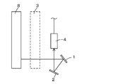
図1は、本発明の実施の形態に係る燃料集合体の外観検査装置の反射鏡の配置および被写体からの光線のカメラヘッドに至るまでの経路を示す説明図である。
図1に示すように、本実施の形態に係る燃料集合体の外観検査装置は、第1反射鏡1と第2反射鏡2の2枚の反射鏡を備え、被写体となる燃料集合体3や内挿物8からの光線を上記の反射鏡により2回反射させ、カメラヘッド4で撮像するものである。このような構成にすることにより、第1反射鏡1で鏡像(反転画像)となった被写体の像は、第2反射鏡2で再度反転し、最終的に正像としてカメラヘッド4に入射される。これにより、固体撮像素子を用いた場合でも解像度の低い市販の電気的な画像反転装置を使用する必要はなくなり、燃料集合体などの被写体の画質の著しい劣化の発生がない画像をモニタに表示することができる。
(1) Reflector Mirror Arrangement FIG. 1 is an explanatory view showing the arrangement of the reflector of the fuel assembly appearance inspection apparatus according to the embodiment of the present invention and the path from the subject to the camera head. is there.
As shown in FIG. 1, the fuel assembly appearance inspection apparatus according to the present embodiment includes two reflecting mirrors, a first reflecting
また、反射鏡を2枚使用して光路長を変更し、光学系を再構成することができるため、被写体とカメラの距離を離すことなく、第1反射鏡1から異なる距離に設置された燃料集合体3及び内挿物8両方の被写体に容易にフォーカスを合わせることができる。
Further, since the optical system can be reconfigured by changing the optical path length using two reflectors, the fuel installed at different distances from the
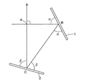
図2は、反射鏡を2枚使用して光学系を再構成した外観検査装置の反射鏡の配置の一例および被写体からの光の光路を示す図である。図2において被写体からの光線の光軸と第1反射鏡の面とが成す角度をα、前記第1反射鏡により反射させた光線の光軸と第2反射鏡の面との成す角度をβとするとき、α+β=135°となるように前記第1反射鏡および第2反射鏡が配置されている。 FIG. 2 is a diagram illustrating an example of the arrangement of reflecting mirrors of an appearance inspection apparatus in which an optical system is reconfigured using two reflecting mirrors, and the optical path of light from a subject. In FIG. 2, the angle formed by the optical axis of the light beam from the subject and the surface of the first reflecting mirror is α, and the angle formed by the optical axis of the light beam reflected by the first reflecting mirror and the surface of the second reflecting mirror is β. , The first reflecting mirror and the second reflecting mirror are arranged so that α + β = 135 °.
このように、α+β=135°に設定されているため、∠BAC=90°となり、第1反射鏡1に水平方向から入射する被写体からの光線の光軸と第2反射鏡2で反射された光線の光軸が直行する。即ち、2枚の反射鏡の距離、相互の位置関係、個々の反射鏡の角度等に関係なく、第2反射鏡2で反射された光線は上方に向かって鉛直に進むため、カメラヘッドに正確に入射させることができる。
Thus, since α + β = 135 ° is set, ∠BAC = 90 °, which is reflected by the second reflecting
なお、上記の第1反射鏡1及び第2反射鏡2としては、ノンブラウニングガラス基板にアルミニウムやクロム膜を蒸着した金属蒸着型裏面鏡、誘電体多層膜反射鏡、およびステンレスなどの金属表面を研磨した金属研磨型表面鏡等を用いることが好ましい。
In addition, as said 1st
(2)カメラヘッドの構成について
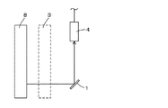
図3は本実施の形態に係る燃料集合体の外観検査装置のカメラヘッドの構成を概念的に示す図である。図3において、縦置きされたカメラヘッド4は水密ケース9、TVカメラ10及びレンズ11から構成される。また、TVカメラ10は撮像管に比べて感度の高い固体撮像素子(図示せず)を具備している。
(2) Configuration of Camera Head FIG. 3 is a diagram conceptually showing the configuration of the camera head of the fuel assembly appearance inspection apparatus according to the present embodiment. In FIG. 3, the vertically placed
以下実施例に基づき、本発明をさらに詳細に説明する。なお、理解し易くするため、便宜上初めに比較例を記載し、次いで実施例を記載する。 Hereinafter, the present invention will be described in more detail based on examples. For ease of understanding, a comparative example is described first for convenience, and then an example is described.
(比較例)
本比較例は、図7に示す1枚の反射鏡を有する従来の燃料集合体の外観検査装置を用いた場合の例であって、燃料集合体位置にはフォーカスが合わせられるが、内挿物位置にはフォーカスを合わすことができない例である。
表1に比較例の外観検査装置のズームレンズの仕様を示す。
(Comparative example)
This comparative example is an example in the case of using the conventional fuel assembly appearance inspection apparatus having one reflecting mirror shown in FIG. 7, and the fuel assembly position is focused. This is an example where the position cannot be focused.
Table 1 shows the specifications of the zoom lens of the appearance inspection apparatus of the comparative example.

ズームレンズとクローズアップレンズを装着したときの、ズームレンズのパラメータは以下のように求められる。
イ.最至近フォーカス位置
最至近フォーカス位置LMIN(気中)は、下記の(1)式により求められる。
LMIN=(fC×S)/(fC+S)・・・(1)
ここで、
fC:クローズアップレンズの焦点距離
S:レンズのフォーカス目盛位置(表1の最至近フォーカス距離がSに相当する)
The parameters of the zoom lens when the zoom lens and the close-up lens are attached are obtained as follows.
I. Nearest focus position Nearest focus position L MIN (in the air) is obtained by the following equation (1).
L MIN = (f C × S) / (f C + S) (1)
here,
f C : focal length of the close-up lens S: focus scale position of the lens (the closest focus distance in Table 1 corresponds to S)
前記表1に記載したFC、Sの値をそれぞれ上記(1)式に代入することにより、LMIN(気中)は以下に示す値となる。
LMIN(気中)=720(mm)
さらに、水中における実距離は、LMIN(気中)を1.33倍することにより以下の(2)に示す値となる。
LMIN(水中)=720(mm)×1.33=958(mm)・・・(2)
By substituting the values of F C and S described in Table 1 into the above equation (1), L MIN (in the air) becomes the following value.
L MIN (in the air) = 720 (mm)
Furthermore, the actual distance in water becomes the value shown in the following (2) by multiplying L MIN (in the air) by 1.33.
L MIN (underwater) = 720 (mm) × 1.33 = 958 (mm) (2)
ロ.最至近フォーカス位置における視野範囲
最至近フォーカス位置における視野範囲Hは、下記の(3)式により求められる。
H=[H’×{ (S−fF)×fC} ]/{ (S+fC)×f]・・・(3)
ここで、
H’:イメージサイズ
S:レンズのフォーカス目盛位置
fF:レンズのフォーカスレンズ部の焦点距離(約60mm)
fC:クローズアップレンズの焦点距離
f:レンズの焦点距離
B. Field-of-view range at the closest focus position The field-of-view range H at the closest focus position is obtained by the following equation (3).
H = [H ′ × {(S−F F ) × f C }] / {(S + f C ) × f] (3)
here,
H ′: image size S: focus scale position of lens f F : focal length of lens focus lens part (about 60 mm)
f C : focal length of close-up lens f: focal length of lens
本比較例においては、H’、f(広角端)、f(望遠端)は以下の通りである。
H’=14(mm)(1インチ16:9型撮像素子を想定)
f(広角端)=30×1.5(エクステンダの倍率)=45(mm)
f(望遠端)=150×1.5(エクステンダの倍率)=225(mm)
上記H’、f(広角端)、f(望遠端)および表1に示したfC、Sの値をそれぞれ(3)式に代入することにより
最至近フォーカス位置LMIN(水中)(958mm)における水平方向の視野範囲、H(広角端)、H(望遠端)は以下の(4)(4’)に示す値となる。
H(広角端)=217(mm)・・・(4)
H(望遠端)= 43(mm)・・・(4’)
In this comparative example, H ′, f (wide-angle end), and f (telephoto end) are as follows.
H ′ = 14 (mm) (1 inch 16: 9 type image sensor is assumed)
f (wide-angle end) = 30 × 1.5 (extender magnification) = 45 (mm)
f (telephoto end) = 150 × 1.5 (extender magnification) = 225 (mm)
By substituting the values of H ′, f (wide-angle end), f (telephoto end) and f C and S shown in Table 1 into Equation (3), the closest focus position L MIN (underwater) (958 mm) The horizontal field-of-view range, H (wide-angle end), and H (telephoto end) are the values shown in the following (4) and (4 ′).
H (wide-angle end) = 217 (mm) (4)
H (telephoto end) = 43 (mm) (4 ′)
ハ.燃料集合体位置および燃料集合体位置における視野範囲
本比較例においては燃料集合体位置LFUELは940mmである。燃料集合体位置LFUELにおけるレンズフォーカス目盛位置S(気中)は、(1)式に表1に記載したfC(1200mm)を代入することにより、以下の(5)に示す値となり、レンズフォーカス目盛位置S(水中)はレンズフォーカス目盛位置S(気中)を1.33倍することにより(5’)に示す値となる。
S(気中)=4338(mm)・・・(5)
S(水中)=5770(mm)・・・(5’)
また燃料集合体位置LFUEL(水中の場合1250mm、気中の場合940mm)における視野範囲H(広角端)、H(望遠端)は(3)式に上記レンズフォーカス目盛位置Sおよび前記f(広角端)、f(望遠端)fCを代入することにより以下の(6)(6’)に示す値となる。
H(広角端)=288(mm)・・・(6)
H(望遠端)= 58(mm)・・・(6’)
C. The fuel assembly position and the field of view range at the fuel assembly position In this comparative example, the fuel assembly position L FUEL is 940 mm. The lens focus scale position S (in the air) at the fuel assembly position L FUEL becomes the value shown in the following (5) by substituting f C (1200 mm) described in Table 1 into the expression (1). The focus scale position S (underwater) becomes the value shown in (5 ′) by multiplying the lens focus scale position S (in air) by 1.33.
S (air) = 4338 (mm) (5)
S (underwater) = 5770 (mm) (5 ')
The field of view range H (wide angle end) and H (telephoto end) at the fuel assembly position L FUEL (1250 mm in the water, 940 mm in the air) are the lens focus scale position S and the f (wide angle) in the equation (3). By substituting (end) and f (telephoto end) f C , the following values (6) and (6 ′) are obtained.
H (wide-angle end) = 288 (mm) (6)
H (telephoto end) = 58 (mm) (6 ′)
ニ.内挿物位置
本比較例における内挿物位置は、水中の場合1650(mm)、気中の場合1240(mm)である。
D. Interpolated Position The interpolated position in this comparative example is 1650 (mm) for underwater and 1240 (mm) for air.
ホ.最遠フォーカス位置および最遠フォーカス位置における視野範囲
また、最遠フォーカス位置LMAX及びその位置における視野範囲Hは下記(7)式および(8)式により求められる。
LMAX=fC・・・(7)
H=(fC/f)×H’・・・・・(8)
上記(7)式より、LMAX(気中)およびLMAX(気中)を1.33倍することにより求められるLMAX(水中)は以下に示す値となる。
LMAX(気中)=1200(mm)
LMAX(水中)=1596(mm)
また、上記(8)式より、H(広角端)、H(望遠端)は以下に示す値となる。
H(広角端)=373(mm)
H(望遠端)= 75(mm)
以上詳述した比較例における被写体距離と画角をまとめて表2に示す。
E. The farthest focus position and the visual field range at the farthest focus position Further, the farthest focus position L MAX and the visual field range H at the position are obtained by the following equations (7) and (8).
L MAX = f C (7)
H = (f C / f) × H ′ (8)
From the above equation (7), L MAX (aerial) and L MAX L is determined by the (in air) 1.33 multiplied MAX (water) are the values below.
L MAX (in the air) = 1200 (mm)
L MAX (underwater) = 1596 (mm)
Further, from the above equation (8), H (wide-angle end) and H (telephoto end) have the following values.
H (wide-angle end) = 373 (mm)
H (telephoto end) = 75 (mm)
Table 2 summarizes the subject distance and the angle of view in the comparative example detailed above.
表2に示したように、比較例においては燃料集合体にフォーカスを合わせることはできるが、内挿物位置の1650mmにはフォーカスを合わせられないことが分かる。 As shown in Table 2, it can be seen that in the comparative example, the fuel assembly can be focused, but the focus cannot be achieved at the insertion position of 1650 mm.
(実施例1)
実施例1は被写体からの光線を第1反射鏡、第2反射鏡の2枚の反射鏡を用いて反射させることによりカメラヘッドに正像を入射させ、前記第1反射鏡と第2反射鏡の2枚の反射鏡の位置を調整して、さらに光学系を再構成して光路長を変更することにより、反射鏡からの距離が異なる位置に設置された燃料集合体および内挿物の両方にフォーカスすることを可能とした燃料集合体の外観検査装置の例である。
Example 1
In the first embodiment, a normal image is incident on the camera head by reflecting light rays from a subject using two reflecting mirrors, a first reflecting mirror and a second reflecting mirror, and the first reflecting mirror and the second reflecting mirror are incident on the camera head. By adjusting the position of the two reflecting mirrors and reconfiguring the optical system to change the optical path length, both the fuel assembly and the interpolator installed at different positions from the reflecting
図4は本発明の実施例1を説明するための図である。図4において、被写体からの入射光線の光軸と第1反射鏡1及び第2反射鏡2の面とが成す角(αおよびβ)の大きさはどちらも67.5°(α+β=135°)であり、このとき水平方向の光軸をもって第1反射鏡1に入射した燃料集合体3からの光線は、第1反射鏡1により反射した後さらに第2反射鏡2により反射し、鉛直方向の光軸をもってカメラヘッド4に入射される。ここで、光軸が交差する点Aから第1反射鏡1の反射面及び第2反射鏡2の反射面までの距離をL1およびL2を共に100mm、L3を141mmとしている。
表3に実施例1のズームレンズに関する仕様を示す。
FIG. 4 is a diagram for explaining the first embodiment of the present invention. In FIG. 4, the angles (α and β) formed by the optical axis of the incident light beam from the subject and the surfaces of the first reflecting
Table 3 shows specifications relating to the zoom lens of Example 1.
なお、実施例1においては2枚の反射鏡を組み合わせて使用することで光路長が長くなるため、表3に示すように(イ)倍率の高いエクステンダを使用するとともに、(ロ)焦点距離の長いクローズアップレンズを使用する。この場合、ズームレンズのパラメータは以下のようになる。 In Example 1, since the optical path length is increased by using two reflecting mirrors in combination, as shown in Table 3, (b) an extender with a high magnification is used, and (b) the focal length is increased. Use a long close-up lens. In this case, the parameters of the zoom lens are as follows.
イ.最至近フォーカス位置
前記(1)式に表3に記載したfC、Sを代入することにより、実施例1の最至近フォーカス位置LMIN(気中)は以下の(9)に示す値となり、水中における実距離はLMIN(気中)×1.33により求めることができ以下の(9’)に示す値となる。
LMIN(気中)=969mm・・・(9)
LMIN(水中)=969mm×1.33=1289mm・・・(9’)
I. Nearest focus position By substituting f C and S described in Table 3 into the above equation (1), the closest focus position L MIN (in the air) of Example 1 becomes a value shown in the following (9), The actual distance in water can be obtained by L MIN (in the air) × 1.33, and is a value shown in the following (9 ′).
L MIN (in the air) = 969 mm (9)
L MIN (underwater) = 969 mm × 1.33 = 1289 mm (9 ′)
ロ.最至近フォーカス位置における視野範囲
実施例1においては、H’、f(広角端)、f(望遠端)は以下の通りである。
H’=14[mm](1インチ16:9型撮像素子を想定)
f(広角端)= 30×2(エクステンダの倍率)= 60(mm)
f(望遠端)=150×2(エクステンダの倍率)=300(mm)
B. Field of view range at the closest focus position In the first embodiment, H ′, f (wide angle end), and f (telephoto end) are as follows.
H ′ = 14 [mm] (1 inch 16: 9 type image sensor is assumed)
f (wide-angle end) = 30 × 2 (extender magnification) = 60 (mm)
f (telephoto end) = 150 × 2 (extender magnification) = 300 (mm)
そして、上記H’、f(広角端)、f(望遠端)および表3に記載したfC、Sの値をそれぞれ(3)式に代入することにより実施例1の最至近フォーカス位置LMIN(水中)(1289mm)における水平方向の視野範囲Hは、以下の(10)、(10’)に示す値となる。
H(広角端)=219(mm)・・・(10)
H(望遠端)= 44(mm)・・・(10’)
Then, the values of H ′, f (wide-angle end), f (telephoto end) and f C and S described in Table 3 are substituted into the expression (3), respectively, to thereby bring the closest focus position L MIN of
H (wide-angle end) = 219 (mm) (10)
H (telephoto end) = 44 (mm) (10 ′)
ロ.燃料集合体位置
第1反射鏡1と第2反射鏡2を第4図に示す距離に置くと、カメラヘッド4から燃料集合体8までの光路長は、前記比較例に比べて図4中の直角二等辺三角形ABCの各辺の和の長さ(約341mm)だけ長くなり、燃料集合体位置LFUELは以下に示す値となる。
LFUEL(水中)=1591(mm)
LFUEL(気中)=1197(mm)
B. Fuel assembly position When the first reflecting
L FUEL (underwater) = 1591 (mm)
L FUEL (in the air) = 1197 (mm)
ハ.燃料集合体位置における視野範囲
燃料集合体位置LFUELにおけるレンズフォーカス目盛位置Sは、前記(1)式にLFUEL=1197mm、fC=2100mmを代入することにより、以下の(11)、(11’)に示す値となる。
S(気中)=2784(mm)・・・(11)
S(水中)=3702(mm)・・・(11’)
C. Field-of-view range at the fuel assembly position The lens focus scale position S at the fuel assembly position L FUEL is calculated by substituting L FUEL = 1197 mm and f C = 2100 mm into the equation (1). It becomes the value shown in ').
S (in the air) = 2784 (mm) (11)
S (underwater) = 3702 (mm) (11 ')
また、燃料集合体位置LFUEL(水中の場合1591mm、気中の場合1197mm)における視野範囲Hは、(3)式に上記レンズフォーカス目盛位置Sおよび前記f(広角端)、f(望遠端)、fCを代入することにより以下の(12)、(12’)に示す値となる。
H(広角端)=273(mm)・・・(12)
H(望遠端)= 55(mm)・・・(12’)
The field of view range H at the fuel assembly position L FUEL (1591 mm in the water, 1197 mm in the air) is the lens focus scale position S and the f (wide-angle end) and f (telephoto end) in the equation (3). By substituting f C , the following values (12) and (12 ′) are obtained.
H (wide-angle end) = 273 (mm) (12)
H (telephoto end) = 55 (mm) (12 ′)
ニ.内挿物位置および内挿物位置における視野範囲
同様にして、内挿物位置(水中の場合1991mm、気中の場合1497mm)における視野範囲を求めると、以下に示す値となる。
H(広角端)=345(mm)
H(望遠端)= 69(mm)
D. Similarly, when the visual field range at the interpolation position (1991 mm for underwater, 1497 mm for the air) is determined, the following values are obtained.
H (wide-angle end) = 345 (mm)
H (telephoto end) = 69 (mm)
ホ.最遠フォーカス位置および最遠フォーカス位置における視野範囲
また、最遠フォーカス位置LMAX及びその位置における視野範囲Hは、前記(7)式、(8)式から、それぞれ以下の(13)、(13’)と(14)、(14’)に示す値となる。
LMAX(気中)=2100(mm)・・・(13)
LMAX(水中)=2793(mm)・・・(13’)
H(広角端)=490(mm)・・・(14)
H(望遠端)= 98(mm)・・・(14’)
実施例1における被写体距離と画角をまとめて表4に示す。
E. The farthest focus position and the visual field range at the farthest focus position Further, the farthest focus position L MAX and the visual field range H at the position are expressed by the following (13) and (13) from the expressions (7) and (8), respectively. ') And the values shown in (14) and (14').
L MAX (in the air) = 2100 (mm) (13)
L MAX (underwater) = 2793 (mm) (13 ')
H (wide-angle end) = 490 (mm) (14)
H (telephoto end) = 98 (mm) (14 ′)
Table 4 summarizes the subject distance and the angle of view in Example 1.
表4に示した結果から、燃料集合体、内挿物の両方の位置がフォーカス範囲に含まれることが分かる。 From the results shown in Table 4, it can be seen that the positions of both the fuel assembly and the insert are included in the focus range.
以上詳述したように、実施例1の燃料集合体の外観検査においては、第1反射鏡および第2反射鏡の2枚の反射鏡を用いて被写体からの光線を2回反射させることよりカメラヘッドに正像を入射させることができ、画像反転装置を用いる場合と比較して、画質の劣化がない画像を得られることが確認できた。また同時に光路長をある程度の自由度を持って長くできることを利用し、ズームレンズ11に装着して使用する市販のクローズアップレンズ及びエクステンダを含めた光学系の再構成を行ない、従来フォーカスが合わなかった内挿物の位置もフォーカス範囲に含められることが確認できた。
As described in detail above, in the appearance inspection of the fuel assembly according to the first embodiment, the camera reflects the light beam from the subject twice using the two reflecting mirrors of the first reflecting mirror and the second reflecting mirror. It was confirmed that a normal image can be made incident on the head, and that an image without deterioration in image quality can be obtained as compared with the case of using an image inverting device. At the same time, utilizing the fact that the optical path length can be increased with a certain degree of freedom, the optical system including the commercially available close-up lens and extender attached to the
実施例1において、図4の直角二等辺三角形ABCの直角を挟む2の辺の長さを100mm、斜辺の長さを141mmとしたが、実際にはこの長さに限定されることはなく、使用するレンズの定数と要求されるフォーカス範囲や視野幅に応じて適宜決められる。 In Example 1, the length of the two sides sandwiching the right angle of the right-angled isosceles triangle ABC in FIG. 4 is 100 mm and the length of the hypotenuse is 141 mm. However, the length is not limited to this actually. It is appropriately determined according to the constant of the lens to be used and the required focus range and field width.
(実施例2)
実施例2は、実施例1と同じレンズを用いた燃料集合体の外観検査装置であって、実施例1と同じ長さの光路長を確保しつつ、反射鏡を挿入するための水平方向のスペースが小さい場合でも反射鏡を挿入することができるよう2枚の反射鏡を配置した例である。図5は本発明の第2の実施例を説明するための図である。実施例2においては被写体からの光線の光軸が構成した直角三角形ABCにおいてABの長さを実施例1よりも短くした。一方、実施例1と同じ長さの光路長を確保するために、ACの長さを実施例1よりも大きくした。
(Example 2)
The second embodiment is a fuel assembly appearance inspection apparatus using the same lens as that of the first embodiment, and in the horizontal direction for inserting a reflecting mirror while ensuring the same optical path length as that of the first embodiment. This is an example in which two reflecting mirrors are arranged so that the reflecting mirrors can be inserted even when the space is small. FIG. 5 is a diagram for explaining a second embodiment of the present invention. In the second embodiment, the length of AB in the right triangle ABC formed by the optical axis of the light beam from the subject is shorter than that in the first embodiment. On the other hand, in order to ensure the same optical path length as that of the first embodiment, the AC length is made longer than that of the first embodiment.
具体的には、図5において、光軸と第1反射鏡1の面とが成す角は60°、光軸と第2反射鏡2の面とが成す角は75°である。このとき光軸の交差する点Aから第1反射鏡1の反射面Bまでの距離L1は72mm、点Aから第2反射鏡2の反射面Cまでの距離L2は125mm、二つの反射鏡間の距離L3は144mmである。
Specifically, in FIG. 5, the angle formed by the optical axis and the surface of the first reflecting
そして、実施例2においても、従来フォーカスが合わなかった内挿物の位置もフォーカス範囲に含められることが確認できた。 Also in Example 2, it was confirmed that the position of the interpolated object that was not focused in the past can be included in the focus range.
このように、本発明によれば水平方向の設置スペースが小さい場合にも2枚の反射鏡を用いて必要な光路長を確保することができる。また、鉛直方向の設置スペースが小さい場合には、水平方向のAB間の長さを長くすることにより、AC間の長さを小さくしても必要な長さの光路長を確保することができる。 Thus, according to the present invention, even when the horizontal installation space is small, the required optical path length can be ensured by using the two reflecting mirrors. Further, when the vertical installation space is small, the length of the optical path length of the necessary length can be ensured even if the length between the ACs is reduced by increasing the length between the ABs in the horizontal direction. .
1 第1反射鏡
2 第2反射鏡
3、20 燃料集合体
4 カメラヘッド
5 カメラ制御器
6 ビデオモニタ
7 画像反転装置
8 内挿物
9 水密ケース
10 TVカメラ
11 レンズ
21 燃料棒
22 シンブル管
23 支持格子
DESCRIPTION OF
Claims (3)
前記反射鏡として第1反射鏡および第2反射鏡の2枚の反射鏡を有し、被写体からの光線を前記第1反射鏡により反射させ、その後第2反射鏡により反射させた後、カメラヘッドに入射させて被写体を撮像すること特徴とする燃料集合体の外観検査装置。 A fuel assembly appearance inspection device that reflects a light beam from a subject by a reflecting mirror and then enters the camera head to image the subject,
The reflecting mirror includes two reflecting mirrors, a first reflecting mirror and a second reflecting mirror. The light beam from the subject is reflected by the first reflecting mirror and then reflected by the second reflecting mirror, and then the camera head. The fuel assembly appearance inspection apparatus is characterized in that an object is imaged by being incident on a fuel.
Priority Applications (1)
| Application Number | Priority Date | Filing Date | Title |
|---|---|---|---|
| JP2008206945A JP5005635B2 (en) | 2008-08-11 | 2008-08-11 | Fuel assembly visual inspection device |
Applications Claiming Priority (1)
| Application Number | Priority Date | Filing Date | Title |
|---|---|---|---|
| JP2008206945A JP5005635B2 (en) | 2008-08-11 | 2008-08-11 | Fuel assembly visual inspection device |
Related Child Applications (1)
| Application Number | Title | Priority Date | Filing Date |
|---|---|---|---|
| JP2012088487A Division JP2012132940A (en) | 2012-04-09 | 2012-04-09 | Visual inspection device for fuel assembly |
Publications (2)
| Publication Number | Publication Date |
|---|---|
| JP2010043896A true JP2010043896A (en) | 2010-02-25 |
| JP5005635B2 JP5005635B2 (en) | 2012-08-22 |
Family
ID=42015396
Family Applications (1)
| Application Number | Title | Priority Date | Filing Date |
|---|---|---|---|
| JP2008206945A Expired - Fee Related JP5005635B2 (en) | 2008-08-11 | 2008-08-11 | Fuel assembly visual inspection device |
Country Status (1)
| Country | Link |
|---|---|
| JP (1) | JP5005635B2 (en) |
Citations (9)
| Publication number | Priority date | Publication date | Assignee | Title |
|---|---|---|---|---|
| JPS63275996A (en) * | 1987-05-08 | 1988-11-14 | Mitsubishi Heavy Ind Ltd | Apparatus for inspecting appearance of fuel assembly |
| JPH0798280A (en) * | 1993-09-29 | 1995-04-11 | Toshiba Corp | Visual inspection apparatus |
| JPH07248396A (en) * | 1994-03-10 | 1995-09-26 | Ikegami Tsushinki Co Ltd | Radiation resistant television camera and monitor |
| JPH095059A (en) * | 1995-06-20 | 1997-01-10 | Nikon Corp | Flatness measuring device |
| JP2000258583A (en) * | 1999-03-05 | 2000-09-22 | Nuclear Fuel Ind Ltd | Measuring device for fuel rod gap in boiling water reactor fuel assembly |
| JP2002040335A (en) * | 2000-07-24 | 2002-02-06 | Tokyo Electron Ind Co Ltd | Conduit inside surface inspection apparatus using mirror |
| JP2002081911A (en) * | 2000-09-11 | 2002-03-22 | Nuclear Fuel Ind Ltd | Method for measuring dimension of fuel assembly and fuel appearance inspection device used for executing it |
| JP2004085250A (en) * | 2002-08-23 | 2004-03-18 | Toshiba Corp | Radiation measuring device |
| JP2005249568A (en) * | 2004-03-04 | 2005-09-15 | Nuclear Fuel Ind Ltd | Fuel body number checking method and tool |
-
2008
- 2008-08-11 JP JP2008206945A patent/JP5005635B2/en not_active Expired - Fee Related
Patent Citations (9)
| Publication number | Priority date | Publication date | Assignee | Title |
|---|---|---|---|---|
| JPS63275996A (en) * | 1987-05-08 | 1988-11-14 | Mitsubishi Heavy Ind Ltd | Apparatus for inspecting appearance of fuel assembly |
| JPH0798280A (en) * | 1993-09-29 | 1995-04-11 | Toshiba Corp | Visual inspection apparatus |
| JPH07248396A (en) * | 1994-03-10 | 1995-09-26 | Ikegami Tsushinki Co Ltd | Radiation resistant television camera and monitor |
| JPH095059A (en) * | 1995-06-20 | 1997-01-10 | Nikon Corp | Flatness measuring device |
| JP2000258583A (en) * | 1999-03-05 | 2000-09-22 | Nuclear Fuel Ind Ltd | Measuring device for fuel rod gap in boiling water reactor fuel assembly |
| JP2002040335A (en) * | 2000-07-24 | 2002-02-06 | Tokyo Electron Ind Co Ltd | Conduit inside surface inspection apparatus using mirror |
| JP2002081911A (en) * | 2000-09-11 | 2002-03-22 | Nuclear Fuel Ind Ltd | Method for measuring dimension of fuel assembly and fuel appearance inspection device used for executing it |
| JP2004085250A (en) * | 2002-08-23 | 2004-03-18 | Toshiba Corp | Radiation measuring device |
| JP2005249568A (en) * | 2004-03-04 | 2005-09-15 | Nuclear Fuel Ind Ltd | Fuel body number checking method and tool |
Also Published As
| Publication number | Publication date |
|---|---|
| JP5005635B2 (en) | 2012-08-22 |
Similar Documents
| Publication | Publication Date | Title |
|---|---|---|
| KR102118242B1 (en) | Auto-focus in low-profile folded optics multi-camera system | |
| US8035681B2 (en) | Panoramic imaging device | |
| JP5741395B2 (en) | Imaging device | |
| US7692869B2 (en) | Image-taking lens unit | |
| JP5579555B2 (en) | Imaging optical system and imaging apparatus | |
| US7612946B2 (en) | Wide-angle lenses | |
| JP2004354572A (en) | Imaging apparatus | |
| JP5677366B2 (en) | Imaging device | |
| EP2966503A1 (en) | Wide-angle imaging device | |
| JP2009288502A (en) | Lens device and imaging apparatus using the same | |
| US7177104B2 (en) | Image-taking optical system | |
| JP5005635B2 (en) | Fuel assembly visual inspection device | |
| JP2012132940A (en) | Visual inspection device for fuel assembly | |
| JP4488023B2 (en) | Imaging device | |
| JP5851701B2 (en) | Camera device for monitoring under radiation environment | |
| JPWO2011077988A1 (en) | Imaging optical system | |
| CN107835959B (en) | Imaging device, imaging optical system, method for manufacturing imaging device, and imaging method | |
| JP2007148051A (en) | Photographing lens unit | |
| US20060083509A1 (en) | Image-taking optical system | |
| JP2015106773A (en) | Imaging device with array optical system | |
| JP2022072586A (en) | Imaging optical system and imaging apparatus | |
| JP2012128301A (en) | Focus adjustment method, focus adjustment program, and imaging apparatus | |
| WO2019208407A1 (en) | Camera module, optical device, and method for manufacturing camera module | |
| JP2003215421A (en) | Image input device and its optical adjustment method | |
| US20180059260A1 (en) | Prad zoom lens design for tilted scintillators |
Legal Events
| Date | Code | Title | Description |
|---|---|---|---|
| A621 | Written request for application examination |
Free format text: JAPANESE INTERMEDIATE CODE: A621 Effective date: 20101224 |
|
| A977 | Report on retrieval |
Free format text: JAPANESE INTERMEDIATE CODE: A971007 Effective date: 20120118 |
|
| A131 | Notification of reasons for refusal |
Free format text: JAPANESE INTERMEDIATE CODE: A131 Effective date: 20120207 |
|
| A521 | Written amendment |
Free format text: JAPANESE INTERMEDIATE CODE: A523 Effective date: 20120409 |
|
| TRDD | Decision of grant or rejection written | ||
| A01 | Written decision to grant a patent or to grant a registration (utility model) |
Free format text: JAPANESE INTERMEDIATE CODE: A01 Effective date: 20120502 |
|
| A01 | Written decision to grant a patent or to grant a registration (utility model) |
Free format text: JAPANESE INTERMEDIATE CODE: A01 |
|
| A61 | First payment of annual fees (during grant procedure) |
Free format text: JAPANESE INTERMEDIATE CODE: A61 Effective date: 20120523 |
|
| FPAY | Renewal fee payment (event date is renewal date of database) |
Free format text: PAYMENT UNTIL: 20150601 Year of fee payment: 3 |
|
| R150 | Certificate of patent or registration of utility model |
Free format text: JAPANESE INTERMEDIATE CODE: R150 |
|
| LAPS | Cancellation because of no payment of annual fees |