JP2010041218A - Imaging element unit, imaging element module, lens barrel, and imaging apparatus - Google Patents
Imaging element unit, imaging element module, lens barrel, and imaging apparatus Download PDFInfo
- Publication number
- JP2010041218A JP2010041218A JP2008199870A JP2008199870A JP2010041218A JP 2010041218 A JP2010041218 A JP 2010041218A JP 2008199870 A JP2008199870 A JP 2008199870A JP 2008199870 A JP2008199870 A JP 2008199870A JP 2010041218 A JP2010041218 A JP 2010041218A
- Authority
- JP
- Japan
- Prior art keywords
- image sensor
- hole
- imaging
- sensor unit
- substrate
- Prior art date
- Legal status (The legal status is an assumption and is not a legal conclusion. Google has not performed a legal analysis and makes no representation as to the accuracy of the status listed.)
- Granted
Links
Images


Abstract
Description
本発明は撮像素子ユニット、撮像素子モジュールおよびレンズ鏡筒並びに撮像装置に関する。 The present invention relates to an imaging element unit, an imaging element module, a lens barrel, and an imaging apparatus.
従来から、撮像素子が組み込まれた撮像素子ユニットが提供されている。
この撮像素子ユニットでは、パッケージの収容凹部に撮像素子を収容するとともに収容凹部をシールガラスで封止した撮像素子部を、配線部材であるフレキシブル基板に実装したのち、前記撮像素子部をホルダに組み付け、シールガラスの上にシールゴムと、前記撮像素子上の撮像に供される部分より他の部分に光が当たることを防ぐ遮光板と光学部材とをこの順番で載置し、さらに、押さえ部材で光学部材をホルダに固定することで、シールガラスと光学素子との間の空間を封止する構造となっている(特許文献1参照)。
In this image sensor unit, after the image sensor is housed in the housing recess and the housing recess is sealed with seal glass, the image sensor unit is mounted on a flexible substrate as a wiring member, and then the image sensor is assembled to the holder. In addition, a seal rubber on the seal glass, and a light shielding plate and an optical member for preventing light from hitting other parts than the part used for imaging on the imaging element are placed in this order, By fixing an optical member to a holder, it has the structure which seals the space between sealing glass and an optical element (refer patent document 1).
このように従来の撮像素子ユニットでは、シールガラスとパッケージとによって撮像素子を封止するとともに、光学部材とシールゴムとシールガラスとによってシールガラスと光学素子との間の空間を封止するなど、構造上の無駄があることから部品点数の削減、組み立て作業性の向上を図る上で不利であり、小型化を図る上でも不利である。
本発明はこのような事情に鑑みなされたものであり、その目的は、コストを低減でき小型化を図る上で有利な撮像素子ユニット、撮像素子モジュールおよびレンズ鏡筒並びに撮像装置を提供することにある。
As described above, in the conventional image sensor unit, the image sensor is sealed with the seal glass and the package, and the space between the seal glass and the optical element is sealed with the optical member, the seal rubber, and the seal glass. The above waste is disadvantageous in reducing the number of parts and improving the assembly workability, and is also disadvantageous in downsizing.
The present invention has been made in view of such circumstances, and an object of the present invention is to provide an imaging element unit, an imaging element module, a lens barrel, and an imaging apparatus that are advantageous in reducing cost and downsizing. is there.
上述の目的を達成するため、本発明の撮像素子ユニットは、撮像面を有する撮像素子と、前記撮像素子が実装された基板と、前記基板を支持する支持体とを備え、前記支持体は、撮像光学系の光路となる孔が貫通形成された本体部と、前記本体部の外周部から突設されたフランジ部とを備え、前記撮像面が前記孔の貫通方向の一端から他端に臨んだ状態で前記孔の貫通方向の一端を閉塞するように前記基板が前記本体部に取着され、前記孔の貫通方向の他端に位置する前記本体部の端部に、前記フランジ部を介して前記支持体が取着される相手側の部材に前記孔の全周にわたる箇所が当接可能な当接部が形成されている。
また本発明の撮像素子モジュールは、撮像素子ユニットと配線部材とを含み、前記撮像素子ユニットは、撮像面を有する撮像素子と、前記撮像素子が実装され前記配線部材に電気的に接続された基板と、前記基板を支持する支持体とを備え、前記支持体は、撮像光学系の光路となる孔が貫通形成された本体部と、前記本体部の外周部から突設されたフランジ部とを備え、前記撮像面が前記孔の貫通方向の一端から他端に臨んだ状態で前記孔の貫通方向の一端を閉塞するように前記基板が前記本体部に取着され、前記孔の貫通方向の他端に位置する前記本体部の端部に、前記フランジ部を介して前記支持体が取着される相手側の部材に前記孔の全周にわたる箇所が当接可能な当接部が形成されている。
また本発明のレンズ鏡筒は、鏡筒と、撮像素子モジュールとを含み、前記撮像素子モジュールは、撮像素子ユニットと配線部材とを含み、前記撮像素子ユニットは、撮像面を有する撮像素子と、前記撮像素子が実装され前記配線部材に電気的に接続された基板と、前記基板を支持する支持体とを備え、前記支持体は、撮像光学系の光路となる孔が貫通形成された本体部と、前記本体部の外周部から突設されたフランジ部とを備え、前記撮像面が前記孔の貫通方向の一端から他端に臨んだ状態で前記孔の貫通方向の一端を閉塞するように前記基板が前記本体部に取着され、前記孔の貫通方向の他端に位置する前記本体部の端部に、前記フランジ部を介して前記支持体が取着される相手側の部材に前記孔の全周にわたる箇所が当接可能な当接部が形成されている。
また本発明の撮像装置は、レンズ鏡筒を有し、前記レンズ鏡筒は、鏡筒と、撮像素子モジュールとを含み、前記撮像素子モジュールは、撮像素子ユニットと配線部材とを含み、前記撮像素子ユニットは、撮像面を有する撮像素子と、前記撮像素子が実装され前記配線部材に電気的に接続された基板と、前記基板を支持する支持体とを備え、前記支持体は、撮像光学系の光路となる孔が貫通形成された本体部と、前記本体部の外周部から突設されたフランジ部とを備え、前記撮像面が前記孔の貫通方向の一端から他端に臨んだ状態で前記孔の貫通方向の一端を閉塞するように前記基板が前記本体部に取着され、前記孔の貫通方向の他端に位置する前記本体部の端部に、前記フランジ部を介して前記支持体が取着される相手側の部材に前記孔の全周にわたる箇所が当接可能な当接部が形成されている。
In order to achieve the above-described object, an imaging element unit of the present invention includes an imaging element having an imaging surface, a substrate on which the imaging element is mounted, and a support that supports the substrate, and the support includes: A main body part through which a hole serving as an optical path of the imaging optical system is formed, and a flange part protruding from an outer peripheral part of the main body part, and the imaging surface faces from one end to the other end in the through direction of the hole In this state, the substrate is attached to the main body so as to close one end in the through direction of the hole, and the end of the main body located at the other end in the through direction of the hole is interposed through the flange portion. Thus, a contact portion is formed on the mating member to which the support is attached.
The imaging element module of the present invention includes an imaging element unit and a wiring member. The imaging element unit includes an imaging element having an imaging surface, and a substrate on which the imaging element is mounted and electrically connected to the wiring member. And a support that supports the substrate, and the support includes a main body portion through which a hole serving as an optical path of the imaging optical system is formed, and a flange portion that protrudes from an outer peripheral portion of the main body portion. The substrate is attached to the main body so as to close one end in the through direction of the hole with the imaging surface facing from one end to the other end in the through direction of the hole. At the end of the main body located at the other end, an abutting portion is formed which can abut over the entire circumference of the hole on the mating member to which the support is attached via the flange. ing.
The lens barrel of the present invention includes a lens barrel and an imaging element module, the imaging element module includes an imaging element unit and a wiring member, and the imaging element unit includes an imaging element having an imaging surface; A main body having a substrate on which the imaging element is mounted and electrically connected to the wiring member; and a support that supports the substrate; and the support is formed with a hole serving as an optical path of the imaging optical system. And a flange portion projecting from the outer peripheral portion of the main body portion so that one end of the hole in the penetrating direction is closed with the imaging surface facing from the one end of the hole in the penetrating direction to the other end. The substrate is attached to the main body, and the end of the main body located at the other end in the penetration direction of the hole is connected to the member on the other side to which the support is attached via the flange. There is a contact part where the entire circumference of the hole can contact It has been made.
The imaging device of the present invention includes a lens barrel, the lens barrel includes a lens barrel and an imaging element module, and the imaging element module includes an imaging element unit and a wiring member, and the imaging The element unit includes an image pickup device having an image pickup surface, a substrate on which the image pickup device is mounted and electrically connected to the wiring member, and a support body that supports the substrate, and the support body includes an image pickup optical system. A body portion through which a hole serving as an optical path is formed and a flange portion projecting from the outer peripheral portion of the body portion, and the imaging surface faces from one end to the other end in the penetration direction of the hole The substrate is attached to the main body so as to close one end in the penetration direction of the hole, and the support is supported on the end of the main body located at the other end in the penetration direction of the hole via the flange portion. All of the holes on the mating member to which the body is attached Abutment portion is contactable is formed over.
そのため、本発明によれば、支持体の本体部の孔の貫通方向の一端を基板で閉塞すると共に、フランジ部を介して支持体が取着される相手側の部材に孔の全周にわたる本体部の当接部を当接させるようにした。
したがって、鏡筒の内部空間内で撮像素子を封止して撮像素子を塵埃などから保護しつつ、部品点数の削減化および構成の簡素化を図れ、部品コスト、組立コストの低減を図るとともに、小型化を図る上で有利となる。
Therefore, according to the present invention, one end of the body of the support body in the penetrating direction of the hole is closed with the substrate, and the body over the entire circumference of the hole is attached to the counterpart member to which the support is attached via the flange portion. The contact part of the part is made to contact.
Therefore, while sealing the image sensor in the interior space of the lens barrel and protecting the image sensor from dust, etc., the number of parts can be reduced and the configuration can be simplified, and the cost of parts and assembly can be reduced. This is advantageous for downsizing.
(第1の実施の形態)
次に本発明の実施の形態について図面を参照して説明する。
本実施の形態では、本発明に係る撮像素子ユニットおよび撮像素子モジュール並びにレンズ鏡筒が撮像装置に組み込まれている場合について説明する。
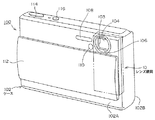
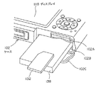
図1は本実施の形態の撮像装置100を前方から見た斜視図、図2は本実施の形態の撮像装置100を後方から見た斜視図、図3は本実施の形態の撮像装置100を下方から見た斜視図、図4はメモリカード132およびバッテリー138の収容状態を説明する説明図、図5は撮像装置100の制御系を示すブロック図である。
図1、図2に示すように、撮像装置100はデジタルスチルカメラである。
撮像装置100は、外装を構成する矩形板状のケース102を有し、ケース102は、前ケース102Aと後ケース102Bとが合わせられて構成されている。
前ケース102Aによりケース102の前面が構成され、後ケース102Bによりケース102の後面が構成されている。
なお、本明細書において、前方とは被写体側をいい、後方とはその反対側をいい、左右は撮像装置100を前方から見た状態でいうものとする。
ケース102の右側部には、図中二点鎖線で示すように、レンズ鏡筒10が組み込まれている。
レンズ鏡筒10には、対物レンズ14と、本発明に係る撮像素子ユニット60(図6参照)と、対物レンズ14で捉えた被写体像を撮像素子ユニット60に導く撮像光学系104などが設けられている。撮像素子ユニット60は後述する撮像素子58(図5参照)を含んで構成されている。
対物レンズ14は前ケース102Aに設けられたレンズ窓103を介してケース102前方に臨んで配置されている。
(First embodiment)
Next, embodiments of the present invention will be described with reference to the drawings.
In the present embodiment, a case will be described in which the imaging element unit, imaging element module, and lens barrel according to the present invention are incorporated in an imaging apparatus.
1 is a perspective view of the
As shown in FIGS. 1 and 2, the
The
The
Note that in this specification, the front refers to the subject side, the rear refers to the opposite side, and the left and right refer to the
A
The
The
ケース102の前面右寄りの箇所には、撮影補助光を出射するフラッシュ108、セルフタイマーランプ110などが設けられている。
ケース102の前面にはカバー112が上下にスライド可能に設けられている。
このカバー112は、図1に示すようにレンズ窓103、フラッシュ108、セルフタイマーランプ110を前方に露出させる下限位置と、これらレンズ窓103、フラッシュ108、セルフタイマーランプ110を覆う上限位置とにスライドされる。
ケース102の上面の左寄り箇所には、シャッタボタン114、電源ボタン116などが設けられている。
ケース102の後面には静止画および動画などの画像や文字や記号などが表示されるディスプレイ118(液晶表示器)、撮像光学系104のズーミング動作を行なわせるためのズームスイッチ120、各種操作を行なうための十字スイッチ122および複数の操作ボタン124が設けられている。
ケース102の左側面には、撮像装置100を静止画撮影モード、動画撮影モード、再生・編集モードなどに切り替えるためのモードスイッチ126が設けられている。
図3、図4に示すように、ケース102の下面には、静止画あるいは動画などの画像などを記録するためのメモリカード132を装脱可能に収容するメモリ収容室102Aと、撮像装置100の電源を構成するバッテリー138を装脱可能に収容するバッテリー収容室102Bとがケース102の前後方向(厚さ方向)に並べて設けられている。
これらメモリ収容室102A、バッテリー収容室102Bはケース102の下面にヒンジを介して連結された開閉蓋102Cによって開閉される。
A
A
As shown in FIG. 1, the
A
On the rear surface of the
On the left side surface of the
As shown in FIGS. 3 and 4, on the lower surface of the
The
図5に示すように、撮像素子58は、撮像光学系104によって結像された被写体像を撮像するCCDやCMOSセンサなどで構成されている。
撮像素子58で撮像された像は撮像信号として画像処理部130に出力され、画像処理部130ではこの撮像信号に基づいて静止画あるいは動画の画像データが生成され、メモリカード(記憶媒体)132に記録される。また、前記画像データは表示処理部134によりディスプレイ118に表示される。
さらに、撮像装置100は、シャッタボタン114、十字スイッチ122、操作ボタン124、モードスイッチ126の操作に応じて、画像処理部130、表示処理部134を制御するCPUなどを含む制御部136を備えている。
As shown in FIG. 5, the
An image picked up by the
Furthermore, the
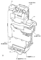
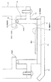
図6はレンズ鏡筒10を斜め前方から見た斜視図、図7はレンズ鏡筒10を斜め後方から見た斜視図である。
図8はレンズ鏡筒10の一部の構成を示す分解斜視図、図9はレンズ鏡筒10の残りの構成を示す分解斜視図である。
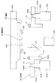
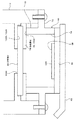
図10は図6のXX線断面図、図11は図6のYY線断面図である。
FIG. 6 is a perspective view of the
FIG. 8 is an exploded perspective view showing a part of the configuration of the
10 is a sectional view taken along line XX of FIG. 6, and FIG. 11 is a sectional view taken along line YY of FIG.
図6乃至図9に示すように、レンズ鏡筒10は、鏡筒12と、対物レンズ14と、撮像素子ユニット60と、撮像光学系104とを含んで構成されている。
本実施の形態では、撮像光学系104は、プリズム16と、ズーム用可動レンズ群18と、フォーカス用可動レンズ群20と、第1の固定レンズ群22と、第2の固定レンズ群24と、第3の固定レンズ群26と、ズーム用可動レンズ群18用の案内機構28と、フォーカス用可動レンズ群20用の案内機構30とを備えている。
さらに、ズーム用可動レンズ群18を移動させる駆動手段32と、フォーカス用可動レンズ群20を移動させる駆動手段34とが設けられている。
As shown in FIGS. 6 to 9, the
In the present embodiment, the imaging
Further, a driving means 32 for moving the zoom
図6、図7に示すように、鏡筒12は、全体として幅および長さ並びに厚さを有する平板形状を呈しており、対物レンズ14と撮像素子ユニット60と撮像光学系104とは鏡筒12の幅方向の中央部で鏡筒12の長さ方向に沿って並べられて配置されている。
鏡筒12は、長さ方向において分割された第1鏡筒分割体1202および第2鏡筒分割体1204と、これら2つの鏡筒分割体1202,1204の間に挟まれる第3鏡筒分割体1206とで構成されている。
鏡筒12の長手方向の一方の半部に第1鏡筒分割体1202が位置し、鏡筒12の長手方向方の他方の半部に第2鏡筒分割体1204が位置し、これら第1鏡筒分割体1202および第2鏡筒分割体1204の間に第3鏡筒分割体1206が介在されている。
As shown in FIGS. 6 and 7, the
The
The first lens barrel divided
図8、図10、図11に示すように、第1鏡筒分割体1202の内部には、下面に開放状の部品収容空間1202Aが設けられており、対物レンズ14はその前面側にレンズ押え1402が位置し後面側に遮光枠1404が位置した状態で、第1鏡筒分割体1202の前面の上部でかつ幅方向の中央部に取着されている。
プリズム16は、図11に示すように、対物レンズ14で捉えた像を下部に向けて(撮像素子ユニット60側に)反射させるものであり、プリズム16は、部品収容空間1202Aで対物レンズ14に臨む箇所に配置されている。
第1の固定レンズ群22とズーム用可動レンズ群18とは、部品収容空間1202A内でプリズム16の下方に配置されている。
第1の固定レンズ群22は、第1鏡筒分割体1202の取り付け部に組み込まれるレンズ2202と、このレンズ2202を前記取り付け部に固定させる押え部材2204(遮光枠を兼ねる)とで構成されている。
As shown in FIGS. 8, 10, and 11, the first lens barrel divided
As shown in FIG. 11, the
The first
The first
図8に示すように、ズーム用可動レンズ群18は、第1のズームレンズ1802と、互いに貼り合わされた第2、第3のズームレンズ1804、1805と、これら第1、第2、第3のズームレンズ1802、1804、1805の外周部をカシメにより支持したズーム用レンズ枠1806とを有している。
ズーム用レンズ枠1806は、第1、第2、第3のズームレンズ1802、1804、1805の周囲に位置している。
ズーム用レンズ枠1806は、これら第1、第2、第3のズームレンズ1802、1804、1805を保持する保持部1810と、この保持部1810から部品収容空間1202A内の幅方向に延在する延在部1812とを有している。
延在部1812には、ロッド挿通孔1814が設けられ、また、鏡筒12の長手方向において互いに対向するフランジ1816、1816が設けられている。
これらフランジ1816、1816には、軸3602、3602を介して雌ねじ3604を有する雌ねじ部材36が鏡筒12の長手方向に移動不能に結合される。
また、延在部1812とは反対側に位置する保持部1810の箇所に係合溝1818が形成されている。
As shown in FIG. 8, the zoom
The
The
The extending
A
Further, an engaging
図8に示すように、ロッド挿通孔1814には、第1鏡筒分割体1202の長さ方向に延在する金属製のメインガイド軸38が滑動可能に挿通されている。
このメインガイド軸38はその長さ方向の両端が第1鏡筒分割体1202の上面を構成する壁部と、第3鏡筒分割体1206の壁部とで支持されている。
メインガイド軸38は第1、第2、第3のズームレンズ1802、1804、1805の光軸と平行して延在している。したがって、メインガイド軸38はズーム用可動レンズ群18を該ズーム用可動レンズ群18の光軸方向に案内している。
係合溝1818には、メインガイド軸38と平行方向に延在するサブガイド軸40(図10参照)が滑動可能に挿通されている。したがって、前記サブガイド軸はズーム用レンズ18がメインガイド軸38の回りに回転することを阻止している。
ズーム用可動レンズ群18用の案内機構28は、これらメインガイド軸38とサブガイド軸40によって構成されている。
As shown in FIG. 8, a metal
Both ends of the
The
A sub guide shaft 40 (see FIG. 10) extending in a direction parallel to the
The
図8に示すように、ズーム用可動レンズ群18を移動させる駆動手段32は、鏡筒12の長さ方向に延在するホルダ3202と、ホルダ3202の上部に設けられたモータ3204と、ホルダ3202に沿って延在しモータ3204により回転駆動される雄ねじ部材3206とを有している。
ホルダ3202は第1鏡筒分割体1202の右側面の欠部に取着され、これにより雄ねじ部材3206が部品収容空間1202Aに位置し、モータ3204は第1鏡筒分割体1202の上面に位置する。
雄ねじ部材3206は雌ねじ部材36の雌ねじ3604に螺合されている。したがって、モータ3204の正逆転によりズーム用可動レンズ群18はメインガイド軸38およびサブガイド軸40に案内されつつそれらの光軸方向に沿って往復移動され、ズーム動作がなされる。
As shown in FIG. 8, the driving means 32 for moving the zoom
The
The
図8に示すように、第3鏡筒分割体1206は、部品収容空間1202A内に臨む内部分1206Aと、部品収容空間1202A外に位置する外部分1206Bとを有している。
第2の固定レンズ群24は、その光軸をズーム用可動レンズ群18の光軸と一致させて内部分1206Aに取着されている。
また、第2固定レンズ24の後面にアイリス(絞り)42が配置されている。
このアイリス42は、第3鏡筒分割体1206の外部分1206Bに取着された駆動部44により開閉される。
As shown in FIG. 8, the third lens barrel divided
The second
An iris (aperture) 42 is disposed on the rear surface of the second fixed
The
図9、図11に示すように、第2鏡筒分割体1204の内部には、本実施の形態では、上下に開放された部品収容空間1204Aが形成されている。
そして、第2鏡筒分割体1204の下部に撮像素子ユニット60が取着されることでこの部品収容空間1204Aの下端は閉塞されている。
フォーカス用可動レンズ群20と第3の固定レンズ群26は、部品収容空間1204A内で第2鏡筒分割体1204の幅方向中央に位置する箇所に配置されている。
As shown in FIGS. 9 and 11, in the present embodiment, a
And the lower end of this
The focus
図9に示すように、フォーカス用可動レンズ群20は、互いに貼り合わされた第1、第2のフォーカスレンズ2002、2004と、これら第1、第2のフォーカスレンズ2002、2004を支持するフォーカス用レンズ枠2006とを有している。
フォーカス用レンズ枠2006は、第1、第2のフォーカスレンズ2002、2004の周囲に位置している。
フォーカス用レンズ枠2006は、これら第1、第2のフォーカスレンズ2002、2004を保持する保持部2010と、この保持部2010から部品収容空間1204A内の幅方向に延在する延在部2012とを有している。
延在部2012には、ロッド挿通孔2014が設けられ、また、鏡筒12の長手方向において互いに対向するフランジ2016、2016が設けられ、これらフランジ2016、2016には、軸4802、4802を介して雌ねじ4804を有する雌ねじ部材48が鏡筒12の長手方向に移動不能に結合される。
また、延在部2012とは反対側に位置する保持部2010の箇所に係合溝2018が形成されている。
As shown in FIG. 9, the focus
The
The
The
Further, an
図9に示すように、ロッド挿通孔2014には、第2鏡筒分割体1204の長さ方向に延在する金属製のメインガイド軸50が滑動可能に挿通されている。
このメインガイド軸50は、図10に示すように、その長さ方向の両端が第3鏡筒分割体1206の壁部と、第2鏡筒分割体1204の下部に設けられた壁部とで支持されている。
メインガイド軸50は第1、第2のフォーカスレンズ2002、2004の光軸と平行して延在している。したがって、メインガイド軸50はフォーカス用可動レンズ群20を該フォーカス用可動レンズ28の光軸方向に案内している。
係合溝2018には、メインガイド軸50と平行して延在するサブガイド軸52(図10参照)が滑動可能に挿通されている。したがって、サブガイド軸52はフォーカス用レンズ20がメインガイド軸50の回りに回転することを阻止している。
フォーカス用可動レンズ群20用の案内機構30は、これらメインガイド軸50とサブガイド軸52によって構成されている。
As shown in FIG. 9, a metal
As shown in FIG. 10, the
The
A sub guide shaft 52 (see FIG. 10) extending parallel to the
The
図9に示すように、フォーカス用可動レンズ群20を移動させる駆動手段34は、鏡筒12の長さ方向に延在するホルダ3402と、ホルダ3402の下部に設けられたモータ3404と、ホルダ3402に沿って延在しモータ3404により回転駆動される雄ねじ部材3406とを有している。
ホルダ3402は第2鏡筒分割体1204の右側面の欠部に取着され、これにより雄ねじ部材3406が部品収容空間1204Aに位置し、モータ3404は第2鏡筒分割体1204の下部に位置する。
雄ねじ部材3406は雌ねじ部材48の雌ねじ4804に螺合されている。したがってモータ3404の正逆転によりフォーカス用可動レンズ群20はメインガイド軸50およびサブガイド軸52に案内されつつそれらの光軸方向に沿って往復移動され、フォーカス動作がなされる。
第3の固定レンズ群26は、フォーカス用可動レンズ群20の下方の部品収容空間1204A箇所に配置されている。
第3の固定レンズ群26は、第2鏡筒分割体1204の取り付け部に組み込まれる第3の固定レンズ群2602と、この第3の固定レンズ群2602を前記取り付け部に固定させる押え部材2604とで構成されている。
As shown in FIG. 9, the driving means 34 for moving the focus
The
The
The third
The third
なお、図11に示すように、部品収容空間1204Aに臨む第2鏡筒分割体1204の後面箇所で第2鏡筒分割体1204Aの上端と第2の固定レンズ群24との間の箇所に設けられた凹凸部1204Cが設けられている。
また、部品収容空間1204Aに臨む第2鏡筒分割体1204の後面箇所で第3の固定レンズ群26と撮像素子ユニット60との間の箇所には凹凸部1204Dが設けられている。
これらの凹凸部1204C、1204Dは以下の理由により設けられている。
すなわち、対物レンズ14、プリズム16、第1の固定レンズ群22、ズーム用可動レンズ群18、第2固定レンズ群24、フォーカス用可動レンズ群20を介して進入してきた光のうち、部品収容空間1204Aに臨む第2鏡筒分割体1204の後面箇所に到達した光が該後面箇所で反射されると、いわゆるフレアあるいはゴーストと呼ばれる反射光が発生する。
このような反射光が撮像素子ユニット60の撮像素子58の撮像面に到達すると、撮像素子58の撮像信号に対して悪影響を及ぼすことになる。
したがって、凹凸部1204C、1204Dを設けることにより前記反射光を防止し、これにより撮像素子58の撮像信号の品質の向上が図られている。
In addition, as shown in FIG. 11, it is provided at a location between the upper end of the
In addition, an uneven portion 1204D is provided at a location between the third
These
That is, among the light that has entered through the
When such reflected light reaches the image pickup surface of the
Therefore, by providing the
図9に示すように、鏡筒12の下部(第2鏡筒分割体124の下部)には撮像素子ユニット60を配設するための鏡筒側取り付け部1205が設けられている。
図15に示すように、鏡筒側取り付け部1205は、矩形状の当接板1220を有し、この当接板1220の内側に撮像光学系104の光路となる孔1222が形成されている。
当接板1220が撮像素子58側に臨む下面は、撮像光学系104の光軸に直交する単一の平面上を延在する当接面1224として形成されている。
当接板1220の周囲には、2つの雌ねじ1210と、2つの位置決めピン1212とが設けられている。
また、当接板1220の周囲には、撮像光学系104の光軸に沿った方向の位置決め用の位置決め面(基準面)1214が形成されている。この位置決め面1214は、2つの雌ねじ1210の周囲の箇所と、2つの雌ねじ1210と離れた箇所の合計3箇所に設けられている。
位置決め面1214は、当接面1224と平行する平面上を延在している。
As shown in FIG. 9, a lens barrel
As shown in FIG. 15, the lens barrel-
The lower surface of the
Two
A positioning surface (reference surface) 1214 for positioning in the direction along the optical axis of the imaging
The
(撮像素子ユニット60)
次に、本発明の要旨である撮像素子ユニット60について詳細に説明する。
図12は撮像素子ユニット60の分解斜視図、図13は鏡筒12および撮像素子ユニット60の断面図、図14は撮像素子ユニット60の平面図、図15は撮像素子モジュール62の鏡筒12への取り付け説明図、図16は撮像素子ユニット60の組み立て説明図である。
図12、図13に示すように、撮像素子ユニット60は、撮像素子58と、基板64と、支持体66とを含んで構成されている。
(Image sensor unit 60)
Next, the
12 is an exploded perspective view of the
As shown in FIGS. 12 and 13, the
(撮像素子58)
撮像素子58はいわゆるベアチップであり、矩形板状を呈している。
図14に示すように、撮像素子58の厚さ方向の一方の面にはその中央に矩形状の平坦な撮像面58Aが形成されている。
撮像面58Aの周囲の矩形枠状の領域には、複数の電極パッド5802と、後述する位置決め用のアライメントマーク5804(基準点)とが設けられている。
(Image sensor 58)
The
As shown in FIG. 14, a rectangular
A plurality of
(基板64)
基板64は、撮像素子58が実装されると共に、撮像素子58に電気的に接続されるものであり、インターポーザーと呼ばれている。
基板64は、図12、図13に示すように、撮像素子58よりも一回り大きな輪郭を有する矩形板状を呈している。
基板64の厚さ方向の一方に位置する表面の中央に撮像素子58が実装されている。
撮像素子58は、撮像面58Aと反対側に位置する背面がダイボンド接着剤などの接着剤によって基板64の表面に接着され固定されている。
基板64の表面には、撮像素子58の電極パッド5802に対応する箇所に不図示の撮像素子58接続用の電極パッドが設けられており、図13に示すように、撮像素子58の電極パッド5802と前記撮像素子58接続用の電極パッドとは金ワイヤ65を介して電気的に接続されている。
また、基板64の背面には、不図示の配線用の外部端子が設けられている。前記外部端子は基板64の内部配線を介して前記撮像素子58接続用の電極パッドと電気的に接続されている。
前記配線用の電極パッドは、撮像素子58に対する信号の授受を行なう配線部材としてのフレキシブル基板68に電気的に接続されている。なお、配線部材としてはフレキシブル基板68の他、有機基板等の多層基板など従来公知のさまざまな配線基板が採用可能である。
本実施の形態では、前記撮像素子58接続用の電極パッドおよび前記配線用の外部端子は、タングステン配線上にニッケルメッキあるいは金メッキを施すことで形成されている。
本実施の形態では、後述するように、基板64とフレキシブル基板68とは、リフロー半田付けによって電気的に接続されており、基板64は、リフロー半田付けが可能な耐熱性を有する材料で形成されている。
このような耐熱性を有する材料としては、例えば、多層高温焼成セラミック基板など従来公知のさまざまな材料が採用可能である。
(Substrate 64)
The
As shown in FIGS. 12 and 13, the
An
The
On the surface of the
Further, an external terminal for wiring (not shown) is provided on the back surface of the
The wiring electrode pads are electrically connected to a
In the present embodiment, the electrode pads for connecting the
In this embodiment, as will be described later, the
As the material having such heat resistance, for example, various conventionally known materials such as a multilayer high-temperature fired ceramic substrate can be adopted.
(支持体66)
図13に示すように、支持体66は、撮像素子58が実装された基板64を支持するものである。
図12、図13、図14に示すように、支持体66は、本体部70と、フランジ部72とを有している。
本体部70は、撮像光学系104の光路となる矩形状の孔74が貫通形成された矩形の筒状に形成されている。
フランジ部72は、本体部70の軸方向の中間部で外周部の2箇所に突設されている。
各フランジ部72にはねじ挿通孔7202が形成されている。
フランジ部72が、本体部70の軸方向の一端に臨む面は、孔74と直交する平面上を延在する平坦な位置決め面7204として形成されている。
本実施の形態では、位置決め面7204は、2つのねじ挿通孔7202の周囲の環状面と、一方のフランジ部72に膨出された円柱部の円形端面とで構成されている。
2つのねじ挿通孔7202の周囲の環状面は、単一の平面上を延在し、前記円形端面は前記単一の平面と平行する別の平面上を延在している。
また、各フランジ部72には、孔74の貫通方向と平行する方向に延在する2つの位置決め孔7206が形成されている。
なお、このような位置決め面7204を設けることにより、後述する撮像面58Aの位置決めを行うと共に、後述する当接面1224と端面7002とを気密に当接させるようにしている。
また、本体部70の軸方向の一端は、平坦な位置決め面7204と平行する単一の平面上を延在する環状の端面7002で形成されている。
この環状の端面7002は、フランジ部72を介して支持体66が取着される相手側の部材である鏡筒12の当接面1224に端面7002の全周にわたる箇所が当接可能な当接部76として形成されている。
(Support 66)
As shown in FIG. 13, the
As shown in FIGS. 12, 13, and 14, the
The
The
Each
The surface where the
In the present embodiment, the
An annular surface around the two
Each
By providing such a
Further, one end of the
The
基板64は、撮像面58Aが孔74の貫通方向の一端から他端に臨んだ状態で孔74の貫通方向の一端を閉塞するように本体部70に取着されている。
本実施の形態では、熱硬化型接着剤により基板64が本体部70に接着されている。以上までをまとめて撮像素子ユニット60と称している。すなわち、撮像素子ユニット60は、撮像素子58と、基板64と、支持体66とを備えている。
The
In the present embodiment, the
支持体66はリフロー半田付けが可能な耐熱性を有し、かつ加工性に優れる(高精度に加工できる)材料で形成されている。
言い換えると、支持体66としては、組立プロセスおよびリフローはんだ付け等の加熱処理によっても寸法変動の少ない材質が好ましく、かつ、加工精度が高く、成形性の良好な材質が好ましい。
また、支持体66としては、後述するように、撮像素子58と、撮像素子58のアライメントマーク5804に対して位置決めされた支持体66との位置関係を維持させることができる必要がある。
本実施の形態では、支持体66は射出成形用エポキシ樹脂で形成されている。
射出成形用エポキシ樹脂は、高精度に金型成形が可能であり、光学的に必要な数μm単位の精度で加工することが可能である。
また、射出成形用エポキシ樹脂は、耐熱性にすぐれ、200℃近傍のリフローはんだ付け温度においても形状変化を起こすことなく初期の加工精度を維持することが可能であり、組立プロセスおよびリフローはんだ付けプロセスにおいて、撮像素子58のアライメントマーク5804に対して位置決めされた支持体66の位置関係を維持させることができるものである。
なお、本実施の形態では、支持体66として高精度射出成形用エポキシ材を用いたが、加工精度、変形等光学的な性能を満たすに満足するならば、液晶ポリマー等の耐熱性プラスチック材料を用いても同様の効果が期待できる。
The
In other words, the
Further, as described later, the
In the present embodiment, the
The epoxy resin for injection molding can be molded with high precision, and can be processed with an accuracy of several μm, which is optically necessary.
In addition, the epoxy resin for injection molding has excellent heat resistance, and can maintain the initial processing accuracy without causing a shape change even at a reflow soldering temperature of around 200 ° C. The assembly process and the reflow soldering process The positional relationship of the
In this embodiment, an epoxy material for high-precision injection molding is used as the
(撮像素子ユニット60の組み立て)
次に撮像素子ユニット60の組み立てについて説明する。
まず、基板64に撮像素子58がダイボンド接着剤によって接着され、金ワイヤ65によって撮像素子58と基板64とが電気的に接続され、これにより基板64に撮像素子58が実装される。
次に、図16を参照して撮像素子58が実装された基板64の支持体66への取り付けについて説明する。
まず、この取り付けに用いる調整治具について説明する。
調整治具は、上部ヘッド200と、定板202と、固定ピン204と、CCDカメラ210と、不図示の画像認識装置、不図示の搭載装置などを含んで構成されている。
上部ヘッド200は、撮像素子58が実装された基板64を、その上下を反転させた状態で、すなわち、下方に撮像素子58の撮像面58Aを臨ませて保持するものである。
上部ヘッド200は、前記搭載装置によって、互いに直交するX軸、Y軸、Z軸に沿って移動され、かつ、それら3つの軸回りに回転されるように構成されている。
定板202は、上部ヘッド200の下方に固定されて設けられ、平面度が保証されたものであり、X軸とY軸を含む平面に沿って平行に延在している。
固定ピン204は、定板202から上方に(Z軸方向に)2つ突設されたものであり、支持体66の2つの位置決め孔7204に挿通されることで支持体66を、X軸、Y軸、Z軸のそれぞれの延在方向に対して移動不能に支持するものである。
CCDカメラ210は、固定ピン204に支持された支持体66の孔74を介して撮像素子58の撮像面58Aを撮像可能に設けられている。
(Assembly of image sensor unit 60)
Next, assembly of the
First, the
Next, with reference to FIG. 16, attachment of the
First, the adjustment jig used for this attachment will be described.
The adjustment jig includes an
The
The
The fixed
Two fixing
The
次に基板64の支持体66への取り付けについて説明する。
撮像素子58が実装された基板64を上部ヘッド200に固定する。
次に、支持体66の位置決め孔7204に固定ピン204を嵌合させ、支持体66を定板202に固定する。
このとき、支持体66の傾きは、支持体66の位置決め面7206で規定され、X軸、Y軸、Z軸の各軸を中心とする回転方向(回転角度θ方向)は位置決め孔7204で規定されている。
次に、支持体66の本体部70の一端に熱硬化型接着材2を塗布し、撮像面58Aのアライメントマーク5804(図14参照)と位置決め孔7204とを、CCDカメラ210で撮影し、その撮影された画像を前記画像認識装置で認識し、その認識結果に基づいて前記搭載装置によって、上部ヘッド200を、X軸方向と、Y軸方向と、Z軸を中心とする回転方向とにそれぞれ動かすことで、撮像素子58と支持体66とのXY平面内での位置決めを行う。
これにより、撮像素子58と支持体66の位置決め孔7204とのXY平面内での位置決めがなされる。
XY平面内での位置決めがなされたならば、前記画像認識装置および搭載装置を用いることで、X軸とZ軸がなす平面内でのRx調整、すなわち、Y軸を中心とする回転方向の位置決めと、Y軸とZ軸がなす平面内でのRy調整、すなわち、X軸を中心とする回転方向の位置決めとを行う。
これにより撮像素子58の撮像面58Aと支持体66の位置決め面7206とが平行をなすように位置決めがなされる。
すなわち、撮像面58Aの中心を通り撮像面58Aに直交する中心軸と孔74の軸心とが合致した状態となる。
次に、撮像素子58と支持体66の相対的な位置関係を保持しながら、基板64をZ軸方向に移動させて基板64の面と支持体66の本体部70の軸方向の他端(環状の端面7002と反対側の端部)とを当て付け、図示しないヒーターを用いて熱硬化型接着剤2を加熱して硬化させる。
これにより、撮像素子58と支持体66の位置決め孔7204および位置決め面7206との位置決めがなされた状態で、撮像素子58が実装された基板64の支持体66の本体部70の一端への組み付けが完了する。
なお、本実施の形態では、支持体66を前述した射出成形用エポキシ樹脂で形成することにより、X軸方向に±30μm、Y軸方向に±30μm、Z軸を中心とする回転方向θに±0.5°、X軸とZ軸がなす平面内でのRx調整で6′、Y軸とZ軸がなす平面内でのRy調整で6′の精度で工程能力指数1.5を超える高い実力で調整できることが確認された。
これにより、基板64の本体部70への組み付けが完了し、撮像素子ユニット60の組み立てが完了する。
Next, attachment of the
The
Next, the fixing
At this time, the inclination of the
Next, the
Thereby, the
If positioning is performed in the XY plane, Rx adjustment in the plane formed by the X axis and the Z axis, that is, positioning in the rotational direction around the Y axis is performed by using the image recognition device and the mounting device. Then, Ry adjustment in the plane formed by the Y axis and the Z axis, that is, positioning in the rotational direction around the X axis is performed.
As a result, positioning is performed so that the
That is, the center axis that passes through the center of the
Next, while maintaining the relative positional relationship between the
As a result, in a state where the
In the present embodiment, the
Thereby, the assembly of the
なお、本実施の形態では、基板64の支持体66への接着に熱硬化型接着剤2を用いた場合について説明したが、腐食性ガスを放出するなど特に不都合を有しない接着剤を用いてもよいことは無論である。熱硬化型接着剤2を用いた場合は、ヒーターを用いることで基板64と支持体66との間に介在された熱硬化型接着剤2をまんべんなく簡単かつ確実に加熱することができるため、熱硬化型接着剤2の硬化を短時間にかつ確実に行うことができ有利である。
In the present embodiment, the case where the
次に撮像素子ユニット60とフレキシブル基板68(図15)との組み付けについて説明する。
撮像素子ユニット60とフレキシブル基板68の組み付けは、基板64の背面の前記配線用の外部端子と、フレキシブル基板68に設けられた配線用の端子とがリフロー半田付けによって電気的に接続されることでなされる。
このように撮像素子ユニット60にフレキシブル基板68が組み付けられることで撮像素子モジュール62が構成される。
Next, assembly of the
The
In this way, the
次に、撮像素子モジュール62の鏡筒12への組み付けについて説明する。
図15に示すように、鏡筒12の当接板1220に支持体66の本体部70の当接部76を臨ませ、鏡筒側取り付け部1205の各位置決めピン1212をフランジ部72の各位置決め孔7204にそれぞれ挿通するとともに、鏡筒側取り付け部1205の各位置決め面(基準面)1214にフランジ部72の各位置決め面(基準面)7206を当て付けることで鏡筒12に対する撮像素子モジュール62の位置決めがなされる。
この位置決めがなされた状態で、ねじNをフランジ部72の各ねじ挿通孔7202を介して各雌ねじ1210に締結する。
これにより、撮像素子ユニット60は光学部材80を鏡筒12の内部に向けて、すなわち、撮像面58Aを鏡筒12内の光路の光軸上に位置させて鏡筒12に取り付けられることになり、撮像素子モジュール62の鏡筒12への組み付けが完了する。
そして、この状態で、当接板1220の当接面1224に本体部70の環状の端面7002(当接部76)が当接し、この際、孔74の貫通方向の一端は、基板64が本体部70に取着されることで閉塞されているので、撮像素子58は、鏡筒12と本体部70と基板64とによって鏡筒12の外部から封止された状態となる。
Next, assembly of the
As shown in FIG. 15, the
With this positioning, the screw N is fastened to each
As a result, the image
In this state, the annular end surface 7002 (contact portion 76) of the
以上説明したように、本実施の形態では、撮像素子ユニット60を、撮像素子58と、撮像素子58が実装された基板64と、支持体66とで構成し、支持体66を本体部70とフランジ部72とで構成し、本体部70の孔74の貫通方向の一端を基板64で閉塞すると共に、フランジ部72を介して支持体66が取着される相手側の部材に孔74の全周にわたる本体部70の当接部76を当接させるようにした。
したがって、鏡筒12の内部空間内で撮像素子58を封止して撮像素子58を塵埃などから保護しつつ、部品点数の削減化および構成の簡素化を図れ、部品コスト、組立コストの低減を図るとともに、小型化を図る上で有利となる。
すなわち、従来の撮像素子ユニットでは、パッケージの収容凹部に撮像素子を収容するとともに収容凹部を封止剤を用いてシールガラスで封止した撮像素子部を、配線部材であるフレキシブル基板に実装したのち、前記撮像素子部をホルダに組み付け、シールガラスの上にシールゴムと光学部材とをこの順番で載置し、さらに、押さえ部材で光学部材をホルダに固定することで、シールガラスと光学素子との間の空間を封止する構造であるため、部品点数が多く、組み立てコストも高いものとなっている。
これに対して、本実施の形態では、撮像素子ユニット60と鏡筒12とを用いて撮像素子58を封止することで、シールガラスが不要となるため、シールガラス周辺の部品も不要となることは無論のこと、シールガラスおよび該シールガラス周辺の部品の占有スペースを大幅に削減できる。
したがって、部品コスト、組み立てコストの低減を図り、小型化を図る上で有利となる。
As described above, in the present embodiment, the
Accordingly, the
In other words, in the conventional image sensor unit, after the image sensor is housed in the housing recess of the package and the housing recess is sealed with seal glass using a sealant, the image sensor portion is mounted on a flexible substrate that is a wiring member. The image sensor unit is assembled to a holder, a seal rubber and an optical member are placed on the seal glass in this order, and the optical member is fixed to the holder with a pressing member, whereby the seal glass and the optical element are Since the space is sealed, the number of parts is large and the assembly cost is high.
On the other hand, in the present embodiment, by sealing the
Therefore, it is advantageous in reducing the component cost and the assembly cost and reducing the size.
また、本実施の形態では、支持体66をリフロー半田付けが可能な耐熱性を有する材料で形成したので、撮像素子58が実装された基板64を支持体66に接着した状態で基板64を配線部材としてのフレキシブル基板68にリフロー半田付けで実装することができる。
したがって、リフロー半田付けによる高温が加わっても支持体66が変形したりダメージを受けることがないので、支持体66に対する撮像素子58(撮像面58A)の位置精度、言い換えると、鏡筒12に対する撮像素子58の位置精度、すなわち、撮影用光軸に対する撮像素子58の位置精度を確保できることは無論のこと、撮像素子ユニット60および撮像素子モジュール62の組み立て作業の簡素化を図る上で有利となる。
また、従来の撮像素子ユニットでは、撮像素子部は、パッケージの収容凹部に撮像素子を収容し収容凹部を封止剤を用いてシールガラスで封止したものであるため、撮像素子部をフレキシブル基板にリフロー半田付けで実装しようとしても次のような不都合が懸念され現実的ではなかった。
すなわち、リフロー半田付けによる高温の温度環境下では、パッケージとシールガラスの熱膨張率の相違によってパッケージとシールガラスとの間に無理なストレスがかかる。あるいは、封止された収容凹部内の空気の膨張によりシールガラスをパッケージに封止する封止剤に無理な圧力がかかる。
これに対して、本実施の形態ではそのような不都合がないため、リフロー半田付けを用いることにより、撮像素子ユニット60および撮像素子モジュール62の組み立て作業の簡素化を図る上で有利となる。
In the present embodiment, since the
Therefore, since the
Further, in the conventional image sensor unit, the image sensor section is a housing in which the image sensor is housed in the housing recess and the housing recess is sealed with seal glass using a sealant. However, even when trying to mount by reflow soldering, the following inconvenience was concerned and it was not realistic.
That is, in a high temperature environment by reflow soldering, an unreasonable stress is applied between the package and the seal glass due to the difference in thermal expansion coefficient between the package and the seal glass. Alternatively, an unreasonable pressure is applied to the sealant that seals the seal glass in the package due to the expansion of air in the sealed recess.
On the other hand, since there is no such inconvenience in the present embodiment, using reflow soldering is advantageous in simplifying the assembling work of the
(第2の実施の形態)
次に第2の実施の形態について説明する。
図17は第2の実施の形態における鏡筒12および撮像素子ユニット60の断面図である。
図17に示すように、第2の実施の形態は、フランジ部72を介して支持体66が取着される相手側の部材である鏡筒12と、孔74の貫通方向の他端に位置する本体部70の端部との間に、環状の弾性部材78が設けられている点が第1の実施の形態と異なっている。
したがって、この第2の実施の形態では、当接部76が弾性部材78により構成されている。
なお、弾性部材78は、相手側の部材(当接板1220の当接面1224)に取着されてもよいし、あるいは、単に当接部76と相手側の部材(当接板1220の当接面1224)の間で挟持される構造であってもよい。
弾性部材78としては、ゴムなどが使用可能である。
第2の実施の形態によれば、第1の実施の形態と同様の効果が奏されることは無論のこと、当接部76と当接面1224との気密性を確保する上でより有利となり、撮像素子58の封止をより確実に行う上で有利となる。
(Second Embodiment)
Next, a second embodiment will be described.
FIG. 17 is a cross-sectional view of the
As shown in FIG. 17, the second embodiment is located at the other end in the penetrating direction of the
Therefore, in the second embodiment, the
The
As the
According to the second embodiment, it is needless to say that the same effects as those of the first embodiment are achieved, and it is more advantageous in securing the airtightness between the
(第3の実施の形態)
次に第3の実施の形態について説明する。
図18は第3の実施の形態における鏡筒12および撮像素子ユニット60の断面図である。
図18に示すように、第3の実施の形態は、第2の実施の形態の変形例であり、弾性部材78の内側の空間は、撮像光学系104の光軸方向から見た場合に、撮像面58Aと同じ輪郭の矩形で形成されている点が第2の実施の形態と異なっている。
第3の実施の形態によれば、第2の実施の形態と同様の効果が奏されることは無論のこと、弾性部材78の内周部分によって、撮像素子58のうち撮像面58Aの周囲の部分に光が照射されることが防止される。
したがって、撮像面58Aの周囲の部分に位置する複数の電極パッド5802(図14)や金ワイヤ65に光が照射することによって発生した迷光が撮像面58Aに悪影響を及ぼすことを防止でき、撮像信号の品質を確保する上で有利となる。
(Third embodiment)
Next, a third embodiment will be described.
FIG. 18 is a cross-sectional view of the
As shown in FIG. 18, the third embodiment is a modification of the second embodiment, and the space inside the
According to the third embodiment, it is needless to say that the same effects as those of the second embodiment can be obtained, and the inner peripheral portion of the
Therefore, it is possible to prevent the stray light generated by irradiating the plurality of electrode pads 5802 (FIG. 14) and the
(第4の実施の形態)
次に第4の実施の形態について説明する。
図19は第4の実施の形態における鏡筒12および撮像素子ユニット60の断面図である。
図19に示すように、第4の実施の形態は、第2の実施の形態の変形例であり、弾性部材78が断面円形のOリングで構成されている点が第2の実施の形態と異なっている。
第4の実施の形態によれば、第2の実施の形態と同様の効果が奏される。
(Fourth embodiment)
Next, a fourth embodiment will be described.
FIG. 19 is a cross-sectional view of the
As shown in FIG. 19, the fourth embodiment is a modification of the second embodiment, and the point that the
According to the fourth embodiment, the same effect as in the second embodiment is achieved.
(第5の実施の形態)
次に第5の実施の形態について説明する。
図20は第5の実施の形態における鏡筒12および撮像素子ユニット60の断面図である。
図20に示すように、第5の実施の形態は、孔74の貫通方向の他端に位置する本体部70の端部に孔74の貫通方向の他端を閉塞するように光透過性を有する光学部材80が配置されている。
さらに、本体部70とは反対に位置する光学部材80の面の外周に環状の弾性部材78が配置されている。
この第5の実施の形態では、当接部76は弾性部材78で構成されている。
また、弾性部材78は、光学部材80の外周の全域と本体部70の当接部76の外周の全域とにわたって延在することで光学部材80を当接部76に載置された状態に保持している。
この際、弾性部材78の大部分が当接板1220(当接面1224)と光学部材80との間に介在し、圧縮されている。
光学部材80としては、例えば、カバーガラス、光学フィルタ、レンズなどが採用可能である。
第5の実施の形態によれば、第2の実施の形態と同様の効果が奏されることは無論のこと、光学部材80と、本体部70と、基板64とによって囲まれた空間に撮像素子58が位置するため、撮像素子58の封止をより確実に行う上で有利となる。
また、光学部材80として光学フィルタあるいはレンズを用いれば、鏡筒12と支持体66との間のデッドスペースを利用して光学フィルタあるいはレンズを配置できるため、レンズ鏡筒10の小型化を図る上で有利となる。
また、光学部材80がカバーガラスである場合、カバーガラスの表面に光学フィルタ機能を有するコート層を形成することで、カバーガラスを光学フィルタとして機能させることができることは無論である。
(Fifth embodiment)
Next, a fifth embodiment will be described.
FIG. 20 is a cross-sectional view of the
As shown in FIG. 20, in the fifth embodiment, light transmission is performed so that the other end in the penetrating direction of the
Further, an annular
In the fifth embodiment, the
Further, the
At this time, most of the
As the
According to the fifth embodiment, it is needless to say that the same effect as that of the second embodiment is obtained, and imaging is performed in a space surrounded by the
Further, if an optical filter or lens is used as the
In addition, when the
(第6の実施の形態)
次に第6の実施の形態について説明する。
図21は第6の実施の形態における鏡筒12および撮像素子ユニット60の断面図である。
図21に示すように、第6の実施の形態は、第5の実施の形態の変形例であり、弾性部材78が光学部材80の外周に沿って塗布、硬化されたシール剤で構成されている点が第5の実施の形態と異なっている。
シール剤は硬化したのちも、弾性を有するものである。
第6の実施の形態によれば、第5の実施の形態と同様の効果が奏される。
(Sixth embodiment)
Next, a sixth embodiment will be described.
FIG. 21 is a cross-sectional view of the
As shown in FIG. 21, the sixth embodiment is a modification of the fifth embodiment, in which the
The sealing agent has elasticity after being cured.
According to the sixth embodiment, the same effect as in the fifth embodiment can be obtained.
(第7の実施の形態)
次に第7の実施の形態について説明する。
図22は第7の実施の形態における鏡筒12および撮像素子ユニット60の断面図である。
図22に示すように、第7の実施の形態は、第5の実施の形態の変形例であり、当接板1220の当接面1224の全域にわたって弾性部材78を介在させた点が第5の実施の形態と異なっている。
第7の実施の形態によれば、第5の実施の形態と同様の効果が奏される。
(Seventh embodiment)
Next, a seventh embodiment will be described.
FIG. 22 is a cross-sectional view of the
As shown in FIG. 22, the seventh embodiment is a modification of the fifth embodiment, and the fifth embodiment is that an
According to the seventh embodiment, the same effect as that of the fifth embodiment is achieved.
(第8の実施の形態)
次に第8の実施の形態について説明する。
図23は第8の実施の形態における鏡筒12および撮像素子ユニット60の断面図である。
図23に示すように、第8の実施の形態は、第5の実施の形態の変形例であり、孔74の貫通方向の他端に位置する本体部70の端部に、孔74の全周にわたって環状の弾性部材78を配置し、さらに、この弾性部材78の上に光透過性を有する光学部材80を配置し、フランジ部72を鏡筒12に取着することにより、光学部材80を当接板1220の当接面1224に当接し、弾性部材78を圧縮するようにしたものである。
第8の実施の形態によれば、第5の実施の形態と同様の効果が奏される。
(Eighth embodiment)
Next, an eighth embodiment will be described.
FIG. 23 is a cross-sectional view of the
As shown in FIG. 23, the eighth embodiment is a modification of the fifth embodiment, and the entire end of the
According to the eighth embodiment, the same effects as those of the fifth embodiment are achieved.
(第9の実施の形態)
次に第9の実施の形態について説明する。
図24は第9の実施の形態における鏡筒12および撮像素子ユニット60の断面図である。
図24に示すように、第9の実施の形態は、第5の実施の形態の変形例であり、弾性部材78を環状に形成し、弾性部材78の内周面に凹溝を形成したものである。
弾性部材78は、孔74の貫通方向の他端に位置する本体部70の端部に取着され、光透過性を有する光学部材80は、その外周部が前記凹溝で挟持されている。
第9の実施の形態では、当接部76が弾性部材78で構成されている。
第9の実施の形態によれば、第5の実施の形態と同様の効果が奏される。
(Ninth embodiment)
Next, a ninth embodiment will be described.
FIG. 24 is a cross-sectional view of the
As shown in FIG. 24, the ninth embodiment is a modification of the fifth embodiment, in which the
The
In the ninth embodiment, the
According to the ninth embodiment, the same effects as those of the fifth embodiment are achieved.
(第10の実施の形態)
次に第10の実施の形態について説明する。
図25は第10の実施の形態における鏡筒12および撮像素子ユニット60の断面図である。
図25に示すように、第10の実施の形態は、第9の実施の形態の変形例であり、本体部70の孔74の形状が第9の実施の形態と異なっている。
すなわち、孔74を形成する本体部70の内周部は、孔74の断面が貫通方向の一端から他端に向かうにつれて次第に小さくなる傾斜面82で形成されている。
言い換えると、撮像面58Aの中心を通り撮像面58Aに直交する中心軸と孔74の軸心とは合致しており、孔74を形成する本体部70の内周部は、撮像面58Aに近接するに従って次第に撮像面58Aの中心軸から離間する傾斜面82で形成されている。
第10の実施の形態によれば、第5の実施の形態と同様の効果が奏されることは無論のこと、次の効果が奏される。
すなわち、光学部材80を透過した光の一部が本体部70の孔74の内周面や撮像面58Aで反射することによって迷光が発生することが懸念される。
特に、光学部材80がカバーガラスの表面に光学フィルタ機能を有するコーティング膜(コート層)を形成したもので構成され、前記コーティング膜が赤外線をカットする機能を有するIRコートである場合、前記迷光が前記コーティング膜と前記カバーガラスとの界面で反射されて撮像面58Aに入射すると、赤いゴーストが発生することが懸念される。
この場合、光学部材80(前記界面)に入射する迷光の入射角(光学部材80の表面と直交する法線に対して迷光がなす角度)が小さいほど、前記迷光は前記界面を透過する成分が多くなり、したがって、前記界面で反射されて撮像面58Aに入射する迷光の光量が減少する。
一方、第10の実施の形態のように、孔74の内周面を傾斜面82とし、この傾斜面82が撮像面58Aと直交する仮想線となす角度を大きくするほど、撮像面58Aで反射されてから傾斜面82で反射された前記迷光が前記界面に入射する入射角が小さくなる。
したがって、傾斜面82が撮像面58Aと直交する仮想線となす角度を所定角度、例えば、5度以上とすることで、前記赤いゴーストを抑制することが可能となり、撮像された画像の品質を確保する上で有利となる。
なお、光学部材80を弾性部材78により挟持する構成は第9の実施の形態と同様である。
(Tenth embodiment)
Next, a tenth embodiment will be described.
FIG. 25 is a cross-sectional view of the
As shown in FIG. 25, the tenth embodiment is a modification of the ninth embodiment, and the shape of the
That is, the inner peripheral portion of the
In other words, the central axis passing through the center of the
According to the tenth embodiment, it is needless to say that the same effects as those of the fifth embodiment can be obtained, and the following effects can be obtained.
That is, there is a concern that stray light may be generated when a part of the light transmitted through the
In particular, when the
In this case, as the incident angle of the stray light incident on the optical member 80 (the interface) (the angle formed by the stray light with respect to the normal perpendicular to the surface of the optical member 80) is smaller, the stray light has a component that passes through the interface. Therefore, the amount of stray light reflected by the interface and incident on the
On the other hand, as in the tenth embodiment, the inner peripheral surface of the
Therefore, by setting the angle formed by the inclined surface 82 to the virtual line orthogonal to the
The configuration in which the
なお、実施の形態においては、撮像装置としてデジタルスチルカメラを例示したが、本発明はビデオカメラやテレビカメラやデジタル一眼レフカメラなどさまざまな撮像装置に無論適用可能である。 In the embodiment, a digital still camera is exemplified as the imaging device. However, the present invention is naturally applicable to various imaging devices such as a video camera, a television camera, and a digital single-lens reflex camera.
10……レンズ鏡筒、58……撮像素子、58A……撮像面、60……撮像素子ユニット、62……撮像素子モジュール、64……基板、66……支持体、70……本体部、72……フランジ部、74……孔、76……当接部、100……撮像装置。
DESCRIPTION OF
Claims (19)
前記撮像素子が実装された基板と、
前記基板を支持する支持体とを備え、
前記支持体は、
撮像光学系の光路となる孔が貫通形成された本体部と、
前記本体部の外周部から突設されたフランジ部とを備え、
前記撮像面が前記孔の貫通方向の一端から他端に臨んだ状態で前記孔の貫通方向の一端を閉塞するように前記基板が前記本体部に取着され、
前記孔の貫通方向の他端に位置する前記本体部の端部に、前記フランジ部を介して前記支持体が取着される相手側の部材に前記孔の全周にわたる箇所が当接可能な当接部が形成されている、
撮像素子ユニット。 An imaging device having an imaging surface;
A substrate on which the image sensor is mounted;
A support for supporting the substrate,
The support is
A main body portion through which a hole serving as an optical path of the imaging optical system is formed;
A flange portion protruding from the outer peripheral portion of the main body portion,
The substrate is attached to the main body so as to close one end in the penetration direction of the hole in a state where the imaging surface faces the other end from the one end in the penetration direction of the hole,
The end of the body located at the other end in the through direction of the hole can be contacted with a member on the other side to which the support body is attached via the flange portion over the entire circumference of the hole. A contact portion is formed,
Image sensor unit.
請求項1記載の撮像素子ユニット。 The abutting portion is configured by an annular end surface formed so as to extend on an end portion of the main body portion on a single plane parallel to the imaging surface.
The image sensor unit according to claim 1.
請求項1記載の撮像素子ユニット。 A positioning surface is formed on the surface opposite to the surface where the flange portion faces the substrate, and extends on a plane orthogonal to the through direction of the hole.
The image sensor unit according to claim 1.
前記当接部は前記弾性部材で構成されている、
請求項1記載の撮像素子ユニット。 An annular elastic member extending over the entire circumference of the end is attached to the end of the main body located at the other end in the through direction of the hole,
The contact portion is configured by the elastic member.
The image sensor unit according to claim 1.
請求項1記載の撮像素子ユニット。 An elastic member to which the contact portion is elastically attached is attached to the counterpart member.
The image sensor unit according to claim 1.
請求項1記載の撮像素子ユニット。 An annular elastic member is interposed between the mating member to which the support is attached via the flange portion and the contact portion.
The image sensor unit according to claim 1.
請求項4乃至6に何れか1項記載の撮像素子ユニット。 The space inside the elastic member is formed with the same contour as the imaging surface when viewed from the optical axis direction of the imaging optical system.
The imaging device unit according to claim 4.
さらに、前記本体部とは反対に位置する前記光学部材の面の外周に環状の弾性部材が配置され、
前記当接部は前記弾性部材で構成されている、
請求項1記載の撮像素子ユニット。 An optical member having a light transmitting property is disposed at the end of the main body located at the other end in the through direction of the hole so as to close the other end in the through direction of the hole,
Furthermore, an annular elastic member is arranged on the outer periphery of the surface of the optical member located opposite to the main body portion,
The contact portion is configured by the elastic member.
The image sensor unit according to claim 1.
請求項1記載の撮像素子ユニット。 The inner peripheral part of the main body part forming the hole is formed with an inclined surface that gradually decreases as the cross section of the hole moves from one end to the other end in the penetration direction.
The image sensor unit according to claim 1.
前記孔を形成する前記本体部の内周部は、前記前記撮像面に近接するに従って次第に前記前記撮像面の中心軸から離間する傾斜面で形成されている、
請求項1記載の撮像素子ユニット。 The central axis passing through the center of the imaging surface and orthogonal to the imaging surface is coincident with the axial center of the hole,
The inner peripheral part of the main body part that forms the hole is formed by an inclined surface that gradually separates from the central axis of the imaging surface as it approaches the imaging surface.
The image sensor unit according to claim 1.
請求項1記載の撮像素子ユニット。 The substrate is formed of a heat-resistant material capable of reflow soldering,
The image sensor unit according to claim 1.
請求項1記載の撮像素子ユニット。 The substrate is composed of a ceramic substrate;
The image sensor unit according to claim 1.
請求項8記載の撮像素子ユニット。 The optical member is any one of a cover glass, an optical filter, and a lens.
The image sensor unit according to claim 8.
請求項8記載の撮像素子ユニット。 The optical member is composed of a cover glass and a coat layer having an optical filter function provided on the surface of the cover glass.
The image sensor unit according to claim 8.
請求項1記載の撮像素子ユニット。 The support is formed of a material having heat resistance that allows reflow soldering and excellent workability.
The image sensor unit according to claim 1.
請求項1記載の撮像素子ユニット。 The support is formed of an injection molding epoxy resin,
The image sensor unit according to claim 1.
前記撮像素子ユニットは、
撮像面を有する撮像素子と、
前記撮像素子が実装され前記配線部材に電気的に接続された基板と、
前記基板を支持する支持体とを備え、
前記支持体は、
撮像光学系の光路となる孔が貫通形成された本体部と、
前記本体部の外周部から突設されたフランジ部とを備え、
前記撮像面が前記孔の貫通方向の一端から他端に臨んだ状態で前記孔の貫通方向の一端を閉塞するように前記基板が前記本体部に取着され、
前記孔の貫通方向の他端に位置する前記本体部の端部に、前記フランジ部を介して前記支持体が取着される相手側の部材に前記孔の全周にわたる箇所が当接可能な当接部が形成されている、
撮像素子モジュール。 Including an image sensor unit and a wiring member;
The image sensor unit is
An imaging device having an imaging surface;
A substrate on which the imaging element is mounted and electrically connected to the wiring member;
A support for supporting the substrate,
The support is
A main body portion through which a hole serving as an optical path of the imaging optical system is formed;
A flange portion protruding from the outer peripheral portion of the main body portion,
The substrate is attached to the main body so as to close one end in the penetration direction of the hole in a state where the imaging surface faces the other end from the one end in the penetration direction of the hole,
The end of the body located at the other end in the through direction of the hole can be contacted with a member on the other side to which the support body is attached via the flange portion over the entire circumference of the hole. A contact portion is formed,
Image sensor module.
前記撮像素子モジュールは、撮像素子ユニットと配線部材とを含み、
前記撮像素子ユニットは、
撮像面を有する撮像素子と、
前記撮像素子が実装され前記配線部材に電気的に接続された基板と、
前記基板を支持する支持体とを備え、
前記支持体は、
撮像光学系の光路となる孔が貫通形成された本体部と、
前記本体部の外周部から突設されたフランジ部とを備え、
前記撮像面が前記孔の貫通方向の一端から他端に臨んだ状態で前記孔の貫通方向の一端を閉塞するように前記基板が前記本体部に取着され、
前記孔の貫通方向の他端に位置する前記本体部の端部に、前記フランジ部を介して前記支持体が取着される相手側の部材に前記孔の全周にわたる箇所が当接可能な当接部が形成されている、
レンズ鏡筒。 Including a lens barrel and an image sensor module;
The image sensor module includes an image sensor unit and a wiring member,
The image sensor unit is
An imaging device having an imaging surface;
A substrate on which the imaging element is mounted and electrically connected to the wiring member;
A support for supporting the substrate,
The support is
A main body portion through which a hole serving as an optical path of the imaging optical system is formed;
A flange portion protruding from the outer peripheral portion of the main body portion,
The substrate is attached to the main body so as to close one end in the penetration direction of the hole in a state where the imaging surface faces the other end from the one end in the penetration direction of the hole,
The end of the body located at the other end in the through direction of the hole can be contacted with a member on the other side to which the support body is attached via the flange portion over the entire circumference of the hole. A contact portion is formed,
Lens barrel.
前記レンズ鏡筒は、鏡筒と、撮像素子モジュールとを含み、
前記撮像素子モジュールは、撮像素子ユニットと配線部材とを含み、
前記撮像素子ユニットは、
撮像面を有する撮像素子と、
前記撮像素子が実装され前記配線部材に電気的に接続された基板と、
前記基板を支持する支持体とを備え、
前記支持体は、
撮像光学系の光路となる孔が貫通形成された本体部と、
前記本体部の外周部から突設されたフランジ部とを備え、
前記撮像面が前記孔の貫通方向の一端から他端に臨んだ状態で前記孔の貫通方向の一端を閉塞するように前記基板が前記本体部に取着され、
前記孔の貫通方向の他端に位置する前記本体部の端部に、前記フランジ部を介して前記支持体が取着される相手側の部材に前記孔の全周にわたる箇所が当接可能な当接部が形成されている、
撮像装置。 Having a lens barrel,
The lens barrel includes a barrel and an image sensor module,
The image sensor module includes an image sensor unit and a wiring member,
The image sensor unit is
An imaging device having an imaging surface;
A substrate on which the imaging element is mounted and electrically connected to the wiring member;
A support for supporting the substrate,
The support is
A main body portion through which a hole serving as an optical path of the imaging optical system is formed;
A flange portion protruding from the outer peripheral portion of the main body portion,
The substrate is attached to the main body so as to close one end in the penetration direction of the hole in a state where the imaging surface faces the other end from the one end in the penetration direction of the hole,
The end of the body located at the other end in the through direction of the hole can be contacted with a member on the other side to which the support body is attached via the flange portion over the entire circumference of the hole. A contact portion is formed,
Imaging device.
Priority Applications (1)
| Application Number | Priority Date | Filing Date | Title |
|---|---|---|---|
| JP2008199870A JP5083101B2 (en) | 2008-08-01 | 2008-08-01 | Imaging device unit, imaging device module, lens barrel, and imaging device |
Applications Claiming Priority (1)
| Application Number | Priority Date | Filing Date | Title |
|---|---|---|---|
| JP2008199870A JP5083101B2 (en) | 2008-08-01 | 2008-08-01 | Imaging device unit, imaging device module, lens barrel, and imaging device |
Publications (2)
| Publication Number | Publication Date |
|---|---|
| JP2010041218A true JP2010041218A (en) | 2010-02-18 |
| JP5083101B2 JP5083101B2 (en) | 2012-11-28 |
Family
ID=42013318
Family Applications (1)
| Application Number | Title | Priority Date | Filing Date |
|---|---|---|---|
| JP2008199870A Expired - Fee Related JP5083101B2 (en) | 2008-08-01 | 2008-08-01 | Imaging device unit, imaging device module, lens barrel, and imaging device |
Country Status (1)
| Country | Link |
|---|---|
| JP (1) | JP5083101B2 (en) |
Cited By (1)
| Publication number | Priority date | Publication date | Assignee | Title |
|---|---|---|---|---|
| JP2019004248A (en) * | 2017-06-13 | 2019-01-10 | キヤノン株式会社 | Imaging device |
Citations (5)
| Publication number | Priority date | Publication date | Assignee | Title |
|---|---|---|---|---|
| JPH0983736A (en) * | 1995-09-20 | 1997-03-28 | Kyocera Corp | Light quantity detection member and image input device having this light quantity detection member |
| JPH11295579A (en) * | 1998-04-10 | 1999-10-29 | Chinontec Kk | Lens device, camera and scope |
| JP2002247427A (en) * | 2001-02-20 | 2002-08-30 | Konica Corp | Image pickup device and method and device for assembling it |
| JP2002344797A (en) * | 2001-05-18 | 2002-11-29 | Matsushita Electric Ind Co Ltd | Imaging device |
| JP2005167432A (en) * | 2003-12-01 | 2005-06-23 | Seiko Precision Inc | Solid state imaging device |
-
2008
- 2008-08-01 JP JP2008199870A patent/JP5083101B2/en not_active Expired - Fee Related
Patent Citations (5)
| Publication number | Priority date | Publication date | Assignee | Title |
|---|---|---|---|---|
| JPH0983736A (en) * | 1995-09-20 | 1997-03-28 | Kyocera Corp | Light quantity detection member and image input device having this light quantity detection member |
| JPH11295579A (en) * | 1998-04-10 | 1999-10-29 | Chinontec Kk | Lens device, camera and scope |
| JP2002247427A (en) * | 2001-02-20 | 2002-08-30 | Konica Corp | Image pickup device and method and device for assembling it |
| JP2002344797A (en) * | 2001-05-18 | 2002-11-29 | Matsushita Electric Ind Co Ltd | Imaging device |
| JP2005167432A (en) * | 2003-12-01 | 2005-06-23 | Seiko Precision Inc | Solid state imaging device |
Cited By (1)
| Publication number | Priority date | Publication date | Assignee | Title |
|---|---|---|---|---|
| JP2019004248A (en) * | 2017-06-13 | 2019-01-10 | キヤノン株式会社 | Imaging device |
Also Published As
| Publication number | Publication date |
|---|---|
| JP5083101B2 (en) | 2012-11-28 |
Similar Documents
| Publication | Publication Date | Title |
|---|---|---|
| JP5040412B2 (en) | Image pickup device package, image pickup device module, lens barrel, and image pickup apparatus | |
| US7860390B2 (en) | Imaging element package, imaging element module and lens barrel, and image capturing apparatus | |
| JP3827089B2 (en) | Lens barrel and imaging device | |
| JP5333250B2 (en) | Imaging device | |
| CN107211087B (en) | Image pickup device, optical apparatus and electronic apparatus having the same, and method of manufacturing image pickup device | |
| JP5871534B2 (en) | Imaging device | |
| JP4525000B2 (en) | Optical device, lens barrel and imaging device | |
| KR101092124B1 (en) | Imaging device portable terminal using the same and image device producing method | |
| TW201346372A (en) | Camera module | |
| JP2014192826A (en) | Imaging device | |
| JP4793285B2 (en) | Image pickup device package, image pickup device module, lens barrel, and image pickup apparatus | |
| JP5083101B2 (en) | Imaging device unit, imaging device module, lens barrel, and imaging device | |
| JP4582407B2 (en) | Image sensor unit, lens barrel, and image pickup apparatus | |
| US9063392B2 (en) | Imaging unit | |
| JP4863040B2 (en) | Lens barrel, imaging device, and manufacturing method thereof | |
| JP4765443B2 (en) | Method for fixing member between lens barrels, lens unit, and imaging device | |
| JP2012185246A (en) | Imaging unit | |
| JP2009141577A (en) | Imaging device package, imaging device module and lens barrel, and imaging apparatus | |
| JP2006262072A (en) | Solid-state image pickup device, lens barrel and imaging device | |
| JP2006215443A (en) | Method for fixing lens frame of lens device, and imaging apparatus and optical apparatus using the same | |
| KR20050045839A (en) | Image pickup apparatus and portable terminal with image pickup apparatus | |
| JP4893948B2 (en) | Imaging unit and imaging apparatus | |
| KR20080079194A (en) | Imaging element package, imaging element module and lens barrel, and image capturing apparatus | |
| JP4374991B2 (en) | Imaging device and method for manufacturing lens device | |
| JP2005012334A (en) | Imaging apparatus and camera equipped with same |
Legal Events
| Date | Code | Title | Description |
|---|---|---|---|
| A621 | Written request for application examination |
Free format text: JAPANESE INTERMEDIATE CODE: A621 Effective date: 20110706 |
|
| A977 | Report on retrieval |
Free format text: JAPANESE INTERMEDIATE CODE: A971007 Effective date: 20120803 |
|
| TRDD | Decision of grant or rejection written | ||
| A01 | Written decision to grant a patent or to grant a registration (utility model) |
Free format text: JAPANESE INTERMEDIATE CODE: A01 Effective date: 20120807 |
|
| A01 | Written decision to grant a patent or to grant a registration (utility model) |
Free format text: JAPANESE INTERMEDIATE CODE: A01 |
|
| A61 | First payment of annual fees (during grant procedure) |
Free format text: JAPANESE INTERMEDIATE CODE: A61 Effective date: 20120820 |
|
| FPAY | Renewal fee payment (event date is renewal date of database) |
Free format text: PAYMENT UNTIL: 20150914 Year of fee payment: 3 |
|
| LAPS | Cancellation because of no payment of annual fees |