JP2010034997A - Motion vector detecting apparatus, motion vector detecting method, and program - Google Patents
Motion vector detecting apparatus, motion vector detecting method, and program Download PDFInfo
- Publication number
- JP2010034997A JP2010034997A JP2008196612A JP2008196612A JP2010034997A JP 2010034997 A JP2010034997 A JP 2010034997A JP 2008196612 A JP2008196612 A JP 2008196612A JP 2008196612 A JP2008196612 A JP 2008196612A JP 2010034997 A JP2010034997 A JP 2010034997A
- Authority
- JP
- Japan
- Prior art keywords
- pixel
- motion vector
- candidate
- evaluation value
- frame
- Prior art date
- Legal status (The legal status is an assumption and is not a legal conclusion. Google has not performed a legal analysis and makes no representation as to the accuracy of the status listed.)
- Granted
Links
Images


Classifications
-
- H—ELECTRICITY
- H04—ELECTRIC COMMUNICATION TECHNIQUE
- H04N—PICTORIAL COMMUNICATION, e.g. TELEVISION
- H04N19/00—Methods or arrangements for coding, decoding, compressing or decompressing digital video signals
- H04N19/50—Methods or arrangements for coding, decoding, compressing or decompressing digital video signals using predictive coding
- H04N19/503—Methods or arrangements for coding, decoding, compressing or decompressing digital video signals using predictive coding involving temporal prediction
- H04N19/51—Motion estimation or motion compensation
- H04N19/513—Processing of motion vectors
- H04N19/517—Processing of motion vectors by encoding
- H04N19/52—Processing of motion vectors by encoding by predictive encoding
Landscapes
- Engineering & Computer Science (AREA)
- Multimedia (AREA)
- Signal Processing (AREA)
- Image Analysis (AREA)
- Compression Or Coding Systems Of Tv Signals (AREA)
Abstract
Description
本発明は、動画像データから動きベクトルを検出して、高能率符号化などの画像処理を行う場合に適用して好適な動きベクトル検出装置及び動きベクトル検出方法、並びにその動きベクトル検出処理を実行するプログラムに関する。 The present invention detects a motion vector from moving image data, and is applied to a case where image processing such as high efficiency encoding is performed. Related to the program.
従来、動画像の処理の分野において、動きの情報、即ち時間的に異なる画像中の物体の動き方向と大きさを用いて、画像処理を効率的に行うことが行われている。例えば、画像の高能率符号化における動き補償フレーム間符号化や、フレーム間時間領域フィルタによるテレビジョン雑音低減装置における動きによるパラメータ制御などに、動き権検出結果を利用することが行われている。動きを求める手法としては、ブロックマッチング法が知られている。ブロックマッチング法は、1フレームの画像を所定画素単位のブロックとしたブロック単位で、そのブロックが動いた領域を探索するものである。このブロックマッチングによる動きベクトル検出処理は、MPEG方式などで実用化されている、動きベクトルを利用した画像処理として、最も普及した一般的な処理である。 2. Description of the Related Art Conventionally, in the field of moving image processing, image processing has been performed efficiently using motion information, that is, the motion direction and size of an object in temporally different images. For example, a motion right detection result is used for motion compensation interframe coding in high-efficiency coding of an image or motion parameter control in a television noise reduction apparatus using an interframe time domain filter. A block matching method is known as a method for obtaining motion. In the block matching method, an area in which a block has moved is searched in block units in which an image of one frame is a block of a predetermined pixel unit. This motion vector detection process by block matching is the most popular general process as an image process using a motion vector, which has been put to practical use in the MPEG system or the like.
ところが、ブロックマッチング法では、ブロックを単位とした処理であるため、各フレーム内の画像の動き検出を必ずしも高精度に検出しているとは言えなかった。このため、本出願人は、先に特許文献1に記載した動きベクトル検出処理を提案した。この動きベクトル検出処理は、画像信号から、各画素位置の動きに関する評価値を検出し、その検出した評価値を評価値テーブルとして持ち、評価値テーブルのデータから、1画面内の候補ベクトルとして複数のベクトルを抽出する。そして、その抽出した複数の候補ベクトルを対象として、全画面の各画素毎に、候補ベクトルによって対応付けられるフレーム間の画素の相関を判定する。その結果、最も相関が高いと判定された画素を結ぶ候補ベクトルを、その画素に対する動きベクトルとして決定するものである。この処理の詳細は、後述する実施の形態の中で説明する。
However, since the block matching method is processing in units of blocks, it cannot be said that motion detection of an image in each frame is necessarily detected with high accuracy. For this reason, the present applicant has proposed the motion vector detection process described in
図24は、この評価値テーブルを使用して、動きベクトルを決定する場合の、先に提案した評価値テーブル形成部の構成を示した図である。図24の構成を説明すると、入力端子1に得られる画像信号は、相関演算部2に供給される。相関演算部2は、参照点メモリ2aと注目点メモリ2bと絶対値算出部2cとを備える。入力端子1に得られる画像信号を、最初に参照点メモリ2aに記憶させ、さらに参照点メモリ2aの記憶データを注目点メモリ2bに移して、参照点メモリ2aと注目点メモリ2bとで1フレームの差がある画素信号を記憶させる。そして、注目点メモリ2bに記憶された画像信号の中の、注目点の画素値と、参照点メモリ2aに記憶された画像信号の中の参照点として選定された画素位置の画素値とを読み出し、両信号の差分を絶対値検出部2cで検出する。検出した差分の絶対値のデータを、相関判定部3に供給する。相関判定部3は、比較部3aを備えて、設定された閾値と比較し、その閾値と比較し、評価値を得る。評価値としては、一例として相関値を用いることができ、例えば差分が閾値以下であるとき、相関が高いとする。
FIG. 24 is a diagram showing a configuration of the previously proposed evaluation value table forming unit when a motion vector is determined using this evaluation value table. 24 will be described. An image signal obtained at the
相関判定部3で得られた評価値は、評価値テーブル算出部4に供給し、評価値積算部4aで評価値を積算し、その積算結果を評価値テーブルメモリ4bに記憶させる。そして、評価値テーブルメモリ4bの記憶データを、評価値テーブルデータとして出力端子5から後段の回路に供給する。
The evaluation value obtained by the
図25は、この図24に示す従来の評価値テーブルを使用して動きベクトルを決定する処理状態の概要を示した図である。図25(a)に示すように、まず現在のフレーム(現フレーム)F1の1フレーム前の画像データである前フレームF0内の、動きベクトルを判断する基準となる画素位置を注目点d0とする。この注目点d0が決まると、その注目点d0の画素位置の周辺の所定範囲でのサーチエリアSAが、現フレームF1内で設定される。サーチエリアSAが設定されると、そのサーチエリアSA内の各画素を参照点d1として評価値が算出され、評価テーブルに登録される。そして、評価値テーブルに登録された値から、サーチエリアSAで最も評価値が高い参照点が、前フレームの注目点から動いた現フレームの画素位置として求まる。このように最も評価値が高い参照点が求まることで、図25(b)に示されるように、その評価値が最も高い参照点と注目点との動き量から、動きベクトルが定まる。
この図24,図25に示す処理を行うことで、評価値テーブルデータに基づいて動きベクトルを検出することができる。
By performing the processing shown in FIGS. 24 and 25, a motion vector can be detected based on the evaluation value table data.
評価値テーブルデータに基づいて動きベクトルを検出する場合、最適な動きベクトルの決定は、評価値テーブルの性能に依存する。図24に示した従来方式では、注目点と未来フレーム(現フレーム)内の探索範囲における、動き候補先画素との相関判定、具体的には輝度値の差分絶対値がある閾値以下であれば、動き候補として、評価値テーブルに度数がカウントされる。 When a motion vector is detected based on the evaluation value table data, the determination of the optimal motion vector depends on the performance of the evaluation value table. In the conventional method shown in FIG. 24, the correlation between the attention point and the motion candidate pixel in the search range in the future frame (current frame), specifically, the absolute value of the difference in luminance value is less than a certain threshold value. The frequency is counted in the evaluation value table as a motion candidate.
ところが、この従来手法による処理では、画像が平坦である箇所や縞模様の箇所などで、空間傾斜が全て、あるいは、一部の方向に対して、ほとんどない画像の場合には、上述した相関判定のみで評価値テーブルを作成すると、誤った動きを足しこんでしまう可能性があり、評価値テーブルの信頼性が低下してしまう。評価値テーブルの信頼性が低下すると、検出される動きベクトルの精度も低下してしまう。
また、従来の評価値テーブルでは、画像中に複数の動きがあった場合には、誤った動きが足されてしまうために、それぞれの動きに起因する評価値が埋もれ、それぞれの動きベクトルを検出することが困難であった。
However, in the processing by this conventional method, the correlation determination described above is performed in the case where the image has almost no spatial inclination in all or a part of the direction where the image is flat or striped. If only the evaluation value table is created, there is a possibility that an erroneous movement is added, and the reliability of the evaluation value table is lowered. When the reliability of the evaluation value table decreases, the accuracy of the detected motion vector also decreases.
In addition, in the conventional evaluation value table, if there are multiple movements in the image, the wrong movement is added, so the evaluation values resulting from each movement are buried and each movement vector is detected. It was difficult to do.
これらの問題点を解決するために本出願人は先に、図26に示した評価値テーブル形成処理構成を提案した。
図26において、図24の構成と異なるのは、相関判定部3の出力を、画素選別部6で選別してから、評価値テーブル算出部4で評価値テーブル4bに書き込ませる点である。
画素選別部6は、相関判定部3の出力を通過させるゲート部6aを備えて、そのゲート部6aの出力を、評価値テーブル算出部4の評価値積算部4aに供給する。
In order to solve these problems, the present applicant has previously proposed the evaluation value table formation processing configuration shown in FIG.
26 differs from the configuration in FIG. 24 in that the output of the
The
画素選別部6では、注目点メモリ2bに記憶された注目画素と、その注目画素に隣接する画素との変化状態を示す注目点空間傾斜パターンを、空間傾斜パターン算出部6bで算出する。また、参照点メモリ2aに記憶された参照画素と、その参照画素に隣接する画素との変化状態を示す参照点空間傾斜パターンについても、空間傾斜パターン算出部6bで算出する。算出した注目点空間傾斜パターンと参照点空間傾斜パターンは、パターン比較部6cに供給して、両パターンの相関を判定する。その比較の際には、空間傾斜パターンメモリ6dを参照する。
そして、パターン比較部6cで得られた相関判定状態の結果により、ゲート部6aの通過を制御する構成とする。
In the
And it is set as the structure which controls passage of the gate part 6a by the result of the correlation determination state obtained by the pattern comparison part 6c.
この図26に示すように、注目画素や参照画素のパターンに応じて画素選別を行うことで、空間傾斜に相関がある参照画素だけが注目画素に対する動き候補を示す評価値テーブルに書き込ませることになる。従って、動きベクトルを検出するための評価値の精度が高くなるという効果を有する。
しかしながら、図26に示した画素選別部6で、信頼性の高い選別を行うためには、注目点と参照点の単なる空間傾斜パターンの相関判定だけでは不十分であった。
As shown in FIG. 26, by performing pixel selection according to the pattern of the target pixel and the reference pixel, only the reference pixel correlated with the spatial inclination is written in the evaluation value table indicating the motion candidate for the target pixel. Become. Therefore, there is an effect that the accuracy of the evaluation value for detecting the motion vector is increased.
However, in order to perform highly reliable sorting by the
即ち、図26の構成で、画素選別部6内のゲート部6aでの画素選別により、動きベクトルの候補が、ある程度の画素に絞られ、評価値テーブルメモリ4bに記憶される評価値テーブルは、ある程度確からしいと思われる動きベクトルの集合となる。しかしながら、その結果得られた評価値テーブルは、依然として大きな数の動きベクトルの集合である。評価値テーブルのデータから、最終的にそのフレームの動きベクトルがいずれであるかを決定するまでには、さらに何らかの処理で評価値テーブル内の動きベクトルを絞る必要があるが、従来提案されている手法では、検出される精度が十分ではなかった。
That is, in the configuration of FIG. 26, the motion vector candidates are narrowed down to a certain number of pixels by pixel selection in the gate unit 6a in the
また、隣接する2つのフレーム間で、動きベクトルがいくつ存在するかは、そのときの画像により異なり、従来の手法で最適な数の動きベクトルが検出されているとは言えなかった。即ち、例えばある手法では、評価値テーブル内の複数の動きベクトルを、最も頻度の高いものから順に、固定的に定めた数だけ抽出するようにしてある。これは、隣接する2つのフレーム間で動きベクトルが何個程度存在するということを経験的に求めて、採取的に動きベクトルとして決定する数を定めたものである。ところが実際には、動きがある画像でも、動きベクトルが2フレーム間で多数存在する比較的動きの激しい画像の場合と、動きベクトルが2フレーム間で僅かな数しか存在しない静止状態に近い画像の場合とがあり、固定的な数とするのには無理がある。 Also, how many motion vectors exist between two adjacent frames differs depending on the image at that time, and it cannot be said that the optimum number of motion vectors has been detected by the conventional method. That is, for example, in a certain method, a plurality of motion vectors in the evaluation value table are extracted in a fixed number in order from the highest frequency. This is an empirically obtained number of motion vectors between two adjacent frames, and a number to be determined as a motion vector by sampling is determined. However, in reality, even in the case of an image with motion, there are a case where the motion vector is relatively intense where there are many motion vectors between two frames, and a case where the motion vector is close to a still state where there are only a few motion vectors between two frames. In some cases, it is impossible to set a fixed number.
本発明はかかる点に鑑みてなされたものであり、動きベクトルを評価した評価値テーブルを使用して動きベクトルを検出する場合の精度を向上させることを目的とする。また、画像中に複数の動きがある場合にも、その複数の動きを的確に検出できるようにすることを目的とする。 The present invention has been made in view of this point, and an object of the present invention is to improve accuracy when a motion vector is detected using an evaluation value table in which the motion vector is evaluated. It is another object of the present invention to make it possible to accurately detect a plurality of movements even when there are a plurality of movements in the image.
本発明は、動画像データから動きベクトルを検出する場合に適用される。
その処理構成としては、動きベクトルの候補となり得るかを評価した動きベクトルの評価値情報を生成する処理と、評価値情報に基づいて動きベクトルの候補を抽出する処理と、抽出された候補となる動きベクトルの中から動きベクトルを決定する動きベクトル決定処理とを行う。
評価値情報を生成する処理は、一方のフレームの注目画素と、他方のフレームのサーチエリア内の参照画素との画素値相関情報に基づいて、参照画素が注目画素の動き候補である可能性を評価した動きベクトルの評価値情報を生成させる処理である。
評価値情報に基づいて動きベクトルを抽出する処理は、一方のフレーム内の注目画素を中心とした所定領域内の画素と、他方のフレーム内の参照画素を中心とした所定領域内の画素とを、領域全体で比較する。その比較結果に基づいて、評価値テーブルの各候補ベクトルを評価して、評価値の高い動きベクトルを候補として抽出する処理である。
The present invention is applied when detecting a motion vector from moving image data.
As the processing configuration, a process for generating motion vector evaluation value information that evaluates whether it can be a motion vector candidate, a process for extracting a motion vector candidate based on the evaluation value information, and an extracted candidate A motion vector determination process for determining a motion vector from the motion vectors is performed.
The process of generating the evaluation value information is based on the pixel value correlation information between the target pixel of one frame and the reference pixel in the search area of the other frame, and the possibility that the reference pixel is a motion candidate of the target pixel. This is processing for generating evaluation value information of the evaluated motion vector.
The process of extracting a motion vector based on the evaluation value information includes a pixel in a predetermined area centered on a target pixel in one frame and a pixel in a predetermined area centered on a reference pixel in the other frame. Compare across regions. Based on the comparison result, each candidate vector of the evaluation value table is evaluated, and a motion vector having a high evaluation value is extracted as a candidate.
本発明によると、評価値情報に基づいて動きベクトルを抽出する処理として、注目画素を中心とした所定領域内の画素と、参照画素を中心とした所定領域内の画素との相関を領域全体比較し、その比較結果に基づいて各候補ベクトルが評価される。従って、評価値情報として選別された画素のデータが、注目画素の周辺領域の状態と参照画素の周辺領域の状態との比較で、さらに選別されることになる。 According to the present invention, as a process of extracting a motion vector based on evaluation value information, a correlation between a pixel in a predetermined area centered on a target pixel and a pixel in a predetermined area centered on a reference pixel is compared with the entire area. Each candidate vector is evaluated based on the comparison result. Accordingly, the pixel data selected as the evaluation value information is further selected by comparing the state of the peripheral region of the target pixel with the state of the peripheral region of the reference pixel.
本発明によると、評価値情報内の動きベクトルの評価値が、さらに各動きベクトルの動き元である注目画素の周辺領域の差分値の和と、動き先である参照画素の周辺領域の差分値の和とで比較されて、候補ベクトルの信頼度が的確に評価されることになる。
このようにして得られた候補ベクトルの信頼度を利用することで、最終的に動きベクトルを候補の中から決定することが、的確に行えるようになる。また、1つの画像内に複数の動きがある場合でも、信頼度の高い候補ベクトルがどの程度あるかによって、その複数のベクトルを的確に決定できるようになる。
According to the present invention, the evaluation value of the motion vector in the evaluation value information further includes the sum of the difference values of the peripheral area of the target pixel that is the motion source of each motion vector and the difference value of the peripheral area of the reference pixel that is the motion destination And the reliability of the candidate vector is accurately evaluated.
By using the reliability of the candidate vector thus obtained, it is possible to accurately determine the motion vector from the candidates. Further, even when there are a plurality of movements in one image, the plurality of vectors can be determined accurately depending on how many candidate vectors have high reliability.
本発明の一実施の形態の例について、図1〜図20を参照して、以下の順序で説明を行う。
1.動きベクトルを検出する全体の構成の概要:図1
2.動きベクトルを検出する全体の処理の概要:図2,図6
3.選別画素データを生成させる構成例:図3,図6〜図8
4.動きベクトル抽出部の構成例:図4
5.選別画素データを生成させる処理例:図5
6.評価値テーブルデータの信頼度を評価する処理例(下位階層のみの例):図9
7.評価値テーブルデータの信頼度を評価する原理の説明:図10
8.評価値テーブルデータの信頼度を評価する処理例(下位と上位の階層を使った例):図11
9.評価値テーブルデータの信頼度を評価する原理の説明(下位と上位の階層を使った例):図12,図13
10.下位階層と上位階層の説明:図14,図15
11.評価値テーブルと評価結果の例:図16〜図20
12.動きベクトル決定部の構成及び動作例:図21〜図23
13.一実施の形態の変形例の説明
An example of an embodiment of the present invention will be described in the following order with reference to FIGS.
1. Overview of overall configuration for detecting motion vectors: FIG.
2. Overview of overall processing for detecting motion vectors: FIGS.
3. Configuration example for generating selected pixel data: FIGS. 3, 6 to 8
4). Configuration example of motion vector extraction unit: FIG.
5). Example of processing for generating selected pixel data: FIG.
6). Example of processing for evaluating reliability of evaluation value table data (example of lower hierarchy only): FIG.
7). Description of the principle for evaluating the reliability of the evaluation value table data: FIG.
8). Example of processing for evaluating reliability of evaluation value table data (example using lower and upper layers): FIG.
9. Description of the principle for evaluating the reliability of the evaluation value table data (example using lower and upper hierarchies): FIGS. 12 and 13
10. Description of lower and upper layers: FIGS. 14 and 15
11. Evaluation value table and examples of evaluation results: FIGS.
12 Configuration and operation example of motion vector determination unit: FIGS.
13. Description of modification of one embodiment
[動きベクトルを検出する全体構成の概要]
本実施の形態においては、動画像データから動きベクトルを検出する動きベクトル検出装置としたものであり、その検出処理として、画素値相関情報より評価値テーブルを形成させて、その評価値テーブルのデータを積算して、動きベクトルを判定するものである。なお、以下の説明では、動きベクトルの評価値情報を記憶したものを評価値テーブルと称するが、この評価値テーブルは、必ずしもテーブル状の記憶情報として構成されてなくてもよく、動くベクトルの評価値を示す情報であれば良い。例えば、評価値をヒストグラム化した情報として、そのヒストグラム化された評価値情報を持つようにしてもよい。
[Overview of overall configuration for detecting motion vectors]
In the present embodiment, a motion vector detection device that detects a motion vector from moving image data is used. As the detection process, an evaluation value table is formed from pixel value correlation information, and the data of the evaluation value table is used. To determine the motion vector. In the following description, what stores motion vector evaluation value information is referred to as an evaluation value table. However, this evaluation value table does not necessarily have to be configured as table-like storage information. Any information indicating a value may be used. For example, the evaluation value information that has been histogrammed may be included as information in which the evaluation values are histogrammed.
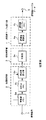
図1は、動きベクトル検出装置の全体構成を示した図である。画像信号入力端子11に得られる画像信号を、評価値テーブル形成部12に供給して、評価値テーブルを形成させる。画像信号は、例えば、各フレーム内の各画素で個別の輝度値が得られるデジタル映像信号である。評価値テーブル形成部12では、サーチエリアと同一の大きさの評価値テーブルを作成する。
FIG. 1 is a diagram illustrating an overall configuration of a motion vector detection device. The image signal obtained at the image
評価値テーブル形成部12が作成した評価値テーブルデータは、動きベクトル抽出部13に供給する。動きベクトル抽出部13では、評価値テーブルから、候補ベクトルとして複数の動きベクトルを抽出する。動きベクトル抽出部13では、評価値テーブルに出現したピークに基づいて、複数の候補ベクトルを抽出する。複数の候補ベクトルを抽出する処理の詳細については後述する。動きベクトル抽出部13で抽出した複数の候補ベクトルは、動きベクトル決定部14に供給する。
動きベクトル決定部14では、候補ベクトル抽出部13において抽出した複数の候補ベクトルを対象として、全画面の画素ごとに、候補ベクトルによって対応付けられるフレーム間の画素間の相関を領域マッチング等により判定する。そして、最も相関の高い対応となった画素又はブロックを結ぶ候補ベクトルを、その画素に対応する動きベクトルとして設定する。これらの動きベクトルを得る処理は、制御部(コントローラ)16による制御で実行される。
設定された動きベクトルのデータは、動きベクトル出力端子15から出力させる。このとき、必要により入力端子11に得られる画像信号に付加して出力させてもよい。出力された動きベクトルデータは、例えば画像データの高能率符号化に使用される。或いは、画像をテレビジョン受像機で表示させる際の高画質化処理に使用される。さらにまた、その他の画像処理に、本例の処理で検出された動きベクトルを使用してもよい。
The evaluation value table data created by the evaluation value
The motion
The set motion vector data is output from the motion
[動きベクトルを検出する全体の処理の概要]
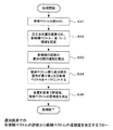
図2のフローチャートは、この動きベクトルを決定するまでの処理例を示したものである。まず、入力した画像信号から評価値テーブルを形成させ(ステップS11)、その形成された評価値テーブルから、候補となる複数のベクトルを抽出する(ステップS12)。そして、その抽出された複数の候補ベクトルの中から、最も相関の高い動きベクトルを決定する(ステップS13)。この図2のフローチャートの処理が、各フレームで実行される。ここまでは、評価値テーブルを使用した動きベクトル検出構成として一般的な構成である。
[Overview of overall processing for detecting motion vectors]
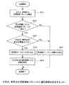
The flowchart in FIG. 2 shows an example of processing until the motion vector is determined. First, an evaluation value table is formed from the input image signal (step S11), and a plurality of candidate vectors are extracted from the formed evaluation value table (step S12). Then, the motion vector having the highest correlation is determined from the extracted candidate vectors (step S13). The process of the flowchart of FIG. 2 is executed in each frame. Up to this point, the configuration is a general configuration as a motion vector detection configuration using the evaluation value table.
そして本実施の形態においては、評価値テーブル形成部12での評価値テーブルの形成処理として、図3に示す構成で行う。ここでの注目点とは、動きベクトルを判定する上での基準となる点(基準点)の画素位置(注目画素)である。参照点とは、その注目点から動いた先である可能性がある点の画素位置(参照画素)である。参照点は、注目点とは後又は前の別のフレームで、注目点の画素位置の近傍(即ちサーチエリア内)の画素である。なお、以下の説明では、注目点と参照点を、注目画素及び参照画素と称する場合がある。注目画素と述べた場合には、注目点の位置の画素を示し、参照画素と述べた場合には、参照点の位置の画素を示す。
In the present embodiment, the evaluation value table forming process in the evaluation value
図3の構成を説明する前に、注目点と参照点との関係について、図6(a)を参照して説明する。
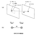
図6(a)に示すように、現在のフレーム(現フレーム)F11の1フレーム前の画像データである前フレームF10内の、動きベクトルを判断する基準となる画素位置を注目点d10とする。この注目点d10が決まると、その注目点d10の画素位置の周辺の所定範囲でのサーチエリアSAが、現フレームF11内で設定される。サーチエリアSAが設定されると、そのサーチエリアSA内の各画素を参照点d11として評価値が算出される。なお、図6(a)では説明のために1点の注目点だけを示してあるが、実際には、1フレーム内の全ての画素又は代表となる複数の画素を、注目点として順に設定して、その注目点ごとに設定されるサーチエリアSA内の各画素を参照点とするものである。
Before describing the configuration of FIG. 3, the relationship between the attention point and the reference point will be described with reference to FIG.
As shown in FIG. 6A, a pixel position serving as a reference for determining a motion vector in the previous frame F10, which is image data one frame before the current frame (current frame) F11, is set as a point of interest d10. When the attention point d10 is determined, a search area SA in a predetermined range around the pixel position of the attention point d10 is set in the current frame F11. When the search area SA is set, an evaluation value is calculated using each pixel in the search area SA as a reference point d11. In FIG. 6 (a), only one point of interest is shown for the sake of explanation. However, in actuality, all the pixels in one frame or a plurality of representative pixels are sequentially set as points of interest. Thus, each pixel in the search area SA set for each attention point is used as a reference point.
[選別画素データを生成させる構成例]
図6(a)に示したように注目点と参照点とを設定して、図3の構成により評価値テーブルのデータが生成される。
図3の例の構成について説明すると、入力端子11に得られる画像信号は、評価値テーブル形成部12内の相関演算部20に供給する。相関演算部20は、参照点メモリ21と注目点メモリ22と絶対値算出部23とを備える。入力端子11に得られる画像信号の中で、参照点として使用されるフレームの画素値を、参照点メモリ21に記憶する。その参照点メモリに記憶されたフレームの信号を、次のフレーム周期に、注目点メモリ22に移す処理が行われる。この例では、参照点が1フレーム前の信号の例である。
[Configuration example for generating selected pixel data]
As shown in FIG. 6A, attention points and reference points are set, and data of the evaluation value table is generated by the configuration of FIG.
The configuration of the example of FIG. 3 will be described. The image signal obtained at the
そして、注目点メモリ22に記憶された注目点の画素値と、参照点メモリ21に記憶された参照点の画素値とを、絶対値算出部23に供給し、両信号の差分の絶対値を検出する。ここでの差分とは、画素信号の輝度値の差分である。検出した絶対値の差分のデータは、相関判定部30に供給する。相関判定部30は、比較部31を備えて、設定された閾値と比較し、評価値を得る。評価値としては、例えば差分が閾値以下であるとき相関が高いとし、閾値を越えたとき相関が低いとした2値の値とする。
Then, the pixel value of the target point stored in the
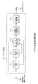
相関判定部30で得られた評価値は、画素選別部40に供給する。画素選別部40は、相関判定部30が出力する2値を選別するゲート部41を備える。このゲート部41を制御する構成として、空間傾斜パターン算出部42と、パターン比較部43と、空間傾斜メモリ44とを備える。
空間傾斜パターン算出部42は、注目画素とその画素に隣接する周辺の8画素との空間傾斜状態を算出し、また参照画素とのその画素に隣接する周辺の8画素との空間傾斜状態を算出する。この注目画素の空間傾斜状態の判断及び参照画素の空間傾斜状態の判断は、それぞれの画素が属するフレーム内で、隣接する周辺画素と比較して判断するものである。
The evaluation value obtained by the correlation determination unit 30 is supplied to the
The spatial inclination
図6(a)及び(b)は、空間傾斜パターンの判断例を示した図である。既に説明したように、隣接した2フレームF10,F11で、注目点と参照点とが設定されると、それぞれのフレーム内で、自らの画素(注目点の画素又は参照点の画素)の輝度値と、周辺の8画素の輝度値が判断される。 FIGS. 6A and 6B are diagrams illustrating an example of determining a spatial inclination pattern. As already described, when the attention point and the reference point are set in the two adjacent frames F10 and F11, the luminance value of the own pixel (the attention point pixel or the reference point pixel) in each frame. Then, the luminance values of the surrounding eight pixels are determined.
図7は、中央の注目画素又は参照画素の輝度値と、周辺画素の輝度値を比較して、空間傾斜符号を判断する際の原理を示した図である。
即ち、図7の左上に示すように、注目点の画素を決めたとき、その注目点に隣接する8つの画素を隣接画素とする。そして、注目点の画素値と、隣接点の画素値とを比較して、画素値(輝度値)の差が、注目点を基準として一定範囲内であるか、一定範囲を+方向に超えた場合であるか、一定範囲をマイナス方向に超えた場合であるか判断する。
図7(a)は、注目点を基準として隣接画素との差が一定範囲内である場合であり、この場合は該当する隣接画素との空間傾斜なしとして、空間傾斜0とする。この空間傾斜0は、隣接画素との空間傾斜がほぼない状態である。図7に示した差を判断する一定範囲を狭くすることで、空間傾斜なしと判断される差分の許容値が狭くなり、一定範囲を広くすることで、空間傾斜なしと判断される差分の許容値が広くなる。
図7(b)は、注目点を基準として、隣接画素の値の方が大きいために、一定範囲を+方向に越えた場合であり、この場合は該当する隣接画素との空間傾斜ありとして、差分符号+とする。
図7(c)は、注目点を基準として、隣接画素の値の方が小さいために、一定範囲を−方向に越えた場合であり、この場合は該当する隣接画素との空間傾斜ありとして、差分符号−とする。
図7では、注目点の空間傾斜の符号を求める処理について説明したが、参照点の場合にも同じである。参照点の場合には、図7の基準が参照点の画素値に変わり、隣接画素はその参照点に隣接する画素の値になる。
FIG. 7 is a diagram illustrating the principle when the spatial inclination code is determined by comparing the luminance value of the central target pixel or reference pixel with the luminance values of the peripheral pixels.
That is, as shown in the upper left of FIG. 7, when a pixel of interest is determined, eight pixels adjacent to the attention point are set as adjacent pixels. Then, the pixel value of the attention point is compared with the pixel value of the adjacent point, and the difference in pixel value (luminance value) is within a certain range with respect to the attention point or exceeds the certain range in the + direction. Whether it is a case or a certain range is exceeded in the minus direction.
FIG. 7A shows a case where the difference from the adjacent pixel is within a certain range with the target point as a reference. In this case, the spatial inclination is 0 with no spatial inclination with the corresponding adjacent pixel. This
FIG. 7B shows the case where the value of the adjacent pixel is larger than the target point, and thus exceeds a certain range in the + direction. In this case, there is a spatial inclination with the corresponding adjacent pixel. The difference code is +.
FIG. 7C shows a case where the value of the adjacent pixel is smaller than the target point as a reference, and thus exceeds a certain range in the − direction. In this case, there is a spatial inclination with the corresponding adjacent pixel. The difference code is-.
In FIG. 7, the processing for obtaining the sign of the spatial inclination of the point of interest has been described. In the case of a reference point, the standard in FIG. 7 changes to the pixel value of the reference point, and the adjacent pixel becomes the value of the pixel adjacent to the reference point.
本実施の形態においては、この図7に示した処理で得た中央の注目画素又は参照画素とその周辺の8画素との空間傾斜符号を見て、空間傾斜パターンを判断する。具体的には、注目画素又は参照画素と周辺の8画素との空間傾斜符号が、全て空間傾斜0である場合には、周辺画素と輝度の変化がほとんどない画素、即ち空間傾斜がない画素と判定する。そして、いずれかの方向で空間傾斜+又は−である場合に、その空間傾斜+又は−となる空間傾斜パターンによって、空間傾斜がある画素と判定する。
In the present embodiment, the spatial inclination pattern is determined by looking at the spatial inclination codes of the center pixel of interest or reference pixel and the surrounding 8 pixels obtained by the processing shown in FIG. Specifically, when the spatial inclination codes of the target pixel or reference pixel and the surrounding eight pixels are all
図8は、空間傾斜パターンの例を示した図である。図8の左側は1フレーム内の9画素のパターンPとして示し、図8の右側は、その9画素のパターンPを拡大して示したものである。図8の例では、注目点(注目画素)d10とその周辺の8画素の例であり、中央の注目点d10と周辺8画素との空間傾斜符号が、全て符号+又は−となっている状態を示している。
図8のパターンは一例であり、周辺8画素との空間傾斜符号の組み合わせで、様々な空間傾斜パターンが設定可能である。
FIG. 8 is a diagram illustrating an example of a spatial inclination pattern. The left side of FIG. 8 is shown as a 9-pixel pattern P in one frame, and the right side of FIG. 8 is an enlarged view of the 9-pixel pattern P. The example of FIG. 8 is an example of the attention point (attention pixel) d10 and the surrounding eight pixels, and the spatial inclination codes of the center attention point d10 and the surrounding eight pixels are all signs + or-. Is shown.
The pattern in FIG. 8 is an example, and various spatial gradient patterns can be set by combining spatial gradient codes with the surrounding eight pixels.
図3の構成の説明に戻ると、画素選別部40内の空間傾斜パターン算出部42では、1フレーム内の各点(注目画素又は参照画素)が、どのような空間傾斜パターンかが算出される。その算出結果がパターン比較部43に送られて、画素選別対象の空間傾斜パターンか否か比較される。この比較を行うために、空間傾斜パターンメモリ44から、選別画素に該当するパターンのデータがパターン比較部43に送られる。
例えば、選別される画素として、図8に示したような空間傾斜パターンの画素であるとした場合には、空間傾斜パターンメモリ44から、この図8のパターンのデータが送られ、パターン比較部43で、そのパターンに該当するか否か比較される。ここでの比較としては、注目点と参照点の双方で行うのが最も好ましいが、いずれか一方でもよい。
Returning to the description of the configuration in FIG. 3, the spatial gradient
For example, if the pixel to be selected is a pixel having a spatial inclination pattern as shown in FIG. 8, the data of the pattern shown in FIG. Then, it is compared whether it corresponds to the pattern. The comparison here is most preferably performed at both the attention point and the reference point, but either one may be used.
このパターン比較部43での比較で、空間傾斜があると判定されるパターンと一致した場合に、画素選別を行う画素であるとして、そのことをゲート部41に指示する。この指示を行うデータが、選別画素データである。
ゲート部41では、選別画素データで選択された画素と指示された場合に、該当する注目点と参照点とに関する評価値を通過させる。
画素選別部40のゲート部41を通過した評価値は、評価値テーブル算出部50に供給し、評価値テーブル算出部50内の評価値積算部51で積算し、その積算結果を評価値テーブルメモリ52に記憶させる。このようにして得られた評価値テーブルメモリ52の記憶データを、評価値テーブルデータとして出力端子12aから後段の回路(動きベクトル抽出部13:図1)に供給する。
さらに本実施の形態においては、ゲート部41に供給される選別画素データを、出力端子12aから、動きベクトル抽出部13に供給する構成としてある。
When the pattern comparison unit 43 matches the pattern determined to have a spatial inclination, the
In the
The evaluation value that has passed through the
Furthermore, in the present embodiment, the selected pixel data supplied to the
[動きベクトル抽出部の構成例]
図4は、図1の動きベクトル抽出部13の構成例を示した図である。動きベクトル抽出部13では、入力端子13aに、評価値テーブルデータと、画素選別データと、画像データとが供給される。
評価値テーブルデータは、図3の評価値テーブル算出部50から供給されるデータであり、評価値テーブルデータ変換部61に供給する。
画素選別データは、図3の画素選別部40のゲート部41から供給されるデータであり、ゲート部41で選別された注目点の画素位置を示すデータである。この注目点の画素選別データを選別画素メモリ73に供給して、該当するフレームの処理が終了するまで記憶させる。
画像データは、処理を行っている各フレームの画像データであり、フレームメモリ74に供給して、該当するフレームの処理が終了するまで記憶させる。
[Configuration example of motion vector extraction unit]
FIG. 4 is a diagram illustrating a configuration example of the motion
The evaluation value table data is data supplied from the evaluation value table calculation unit 50 in FIG. 3 and is supplied to the evaluation value table
The pixel selection data is data supplied from the
The image data is image data of each frame being processed, and is supplied to the
評価値テーブルデータ変換部61では、供給された評価値テーブルデータを、頻度値或いはその微分値などのデータに変換する。変換されたデータは、頻度順ソート処理部62で、1フレーム内で候補ベクトルを頻度順に並び替える処理を行う。頻度順に並び替えられた候補ベクトルの評価値テーブルデータは、候補ベクトル信頼度判定部70に供給する。
The evaluation value table
候補ベクトル信頼度判定部70では、頻度順に並び替えられた評価値テーブルデータを候補ベクトル評価部71に供給する。この候補ベクトル評価部71では、選別画素メモリ73に記憶された注目点の選別画素データで示される各選別画素の位置での、候補ベクトルの信頼性の評価を行う。評価された結果は、候補ベクトル信頼度判定部72に供給し、候補ベクトルの信頼度データを生成させて、その候補ベクトルの信頼度データを、出力端子13bから後段の処理部(図1の動きベクトル決定部14)に供給する。
The candidate vector reliability determination unit 70 supplies the evaluation value table data rearranged in order of frequency to the candidate
[選別画素データを生成させる処理例]
次に、図3及び図4の構成で、選別画素データの生成と、その生成された選別画素データを使用した信頼性の評価が行われる処理例について説明する。
まず、図5のフローチャートを参照して、選別画素を決定する処理状態について説明する。この選別画素を決定する処理は、図3の構成で実行される。
図5に沿って説明すると、図3に示した構成での処理は、注目点と参照点の空間傾斜パターンを用いて、評価値の選別を行う処理である。以下のフローチャートでは、画素選別部40での処理を中心にして説明する。
[Example of processing for generating selected pixel data]
Next, a description will be given of a processing example in which selection pixel data is generated and reliability is evaluated using the generated selection pixel data in the configuration of FIGS. 3 and 4.
First, the processing state for determining the selected pixel will be described with reference to the flowchart of FIG. The process of determining the selected pixel is executed with the configuration of FIG.
If it demonstrates along FIG. 5, the process by the structure shown in FIG. 3 is a process which selects an evaluation value using the spatial inclination pattern of an attention point and a reference point. In the following flowchart, the process in the
この図5のフローチャートの例では、図8に示す空間傾斜パターンを使用した例である。即ち、隣接8画素と中央の1画素の9画素のパターンとして、中央の注目点又は参照点と、隣接8画素との関係が、全て0以外(即ち符号+又は−)である場合である。 The example of the flowchart in FIG. 5 is an example in which the spatial inclination pattern shown in FIG. 8 is used. That is, as a 9-pixel pattern of 8 adjacent pixels and 1 central pixel, the relationship between the central attention point or reference point and the adjacent 8 pixels is all other than 0 (that is, sign + or −).
まず、空間傾斜パターン算出部42で、注目点との隣接差分による空間傾斜パターンから空間傾斜符号を算出し、参照点についても、同様に参照点との隣接差分による空間傾斜パターンから空間傾斜符号を算出し、空間傾斜パターンを得る(ステップS21)。
そして、予め空間傾斜パターンメモ44に用意されていた空間傾斜パターンと一致するか否か判断する(ステップS22)。この判断で、一致した場合には、注目点の画素の輝度値と参照点の画素の輝度値が、所定の閾値以下で同じと判断されるか否か判断する(ステップS23)。
ここで、同じと判断された場合には、ゲート部41を通過させて、該当する評価値を評価値テーブルに積算させる(ステップS24)。そして、その注目点を選別画素とする情報を保持させる(ステップS25)。
また、ステップS22で空間傾斜パターンが一致しない場合と、ステップS23で注目点と参照点との差分が閾値以下でない場合とには、そのときの評価値のゲート部41の通過を阻止させて、評価値テーブルへの書き込みを禁止させる(ステップS26)。
First, the spatial inclination
And it is judged whether it corresponds with the space inclination pattern previously prepared for the space inclination pattern memo 44 (step S22). If they match in this determination, it is determined whether the luminance value of the pixel of interest and the luminance value of the pixel of the reference point are determined to be the same at a predetermined threshold value or less (step S23).
Here, if it is determined that they are the same, the corresponding evaluation values are accumulated in the evaluation value table through the gate unit 41 (step S24). And the information which makes the attention point the selection pixel is hold | maintained (step S25).
Further, when the spatial inclination patterns do not match in step S22 and in the case where the difference between the attention point and the reference point is not less than or equal to the threshold value in step S23, the evaluation value at that time is prevented from passing through the
[評価値テーブルデータの信頼度を評価する処理例]
次に、図9のフローチャートを参照して、このようにして得られた評価値テーブル内の評価値を評価する処理例について説明する。この評価値テーブル内の評価値を評価する処理は、図4に示した動きベクトル抽出部13で実行される。
まず、候補ベクトル信頼度評価部71では、頻度順ソート処理部62から、候補ベクトルを読み出す(ステップS31)。この候補ベクトルは、頻度順ソート処理部62で頻度順にソートされたものから抽出した候補ベクトルであり、1フレーム内の候補ベクトルの内で、頻度が高いものから上位の所定順位のものを候補ベクトルとする。例えば、ここでは1フレーム内で頻度が最も高いものから順に、20番目までの候補ベクトルを取り出す。
[Processing example to evaluate the reliability of evaluation value table data]
Next, a processing example for evaluating the evaluation values in the evaluation value table obtained in this way will be described with reference to the flowchart of FIG. The process of evaluating the evaluation value in the evaluation value table is executed by the motion
First, the candidate vector
そして、候補ベクトル信頼度評価部71で、選別画素データメモリ73から供給された選別画素データで示された注目点の選別画素について、それぞれの注目画素を中心とした所定の領域を設定する。そして、その注目画素から、ステップS31で取り出したそれぞれの候補ベクトルで示される動き先候補の参照点を設定する。例えば上述したように20番目までの候補ベクトルを取出した場合には、1つの注目点の選別画素について、20個の参照画素を設定することになる。
複数の参照画素が設定されると、それぞれの参照画素を中心とした所定の領域を設定する。この領域のサイズは、注目画素を中心として設定した領域のサイズと同じである。
そして、選別された注目画素を中心とした領域の画素値と、それぞれの参照画素を中心とした領域の画素値を、フレームメモリ74から取得する(ステップS32)。
各領域内の画素値を取得すると、注目画素を中心とした領域内の各画素の画素値と、各参照画素を中心とした領域内の各画素の画素値との差分を取得し、その差分の領域毎の絶対値和を算出する(ステップS33)。この算出で、選別された注目画素からの候補ベクトルの内で、差分絶対値和が最小値となる参照画素の候補ベクトルを、信頼度が高いと判断して、信頼度のカウント値を+1する(ステップS34)。
そして、1フレーム内の全ての選別された注目画素について、同様の候補ベクトルの信頼性の評価をした後、候補ベクトルの信頼度を決定する(ステップS35)。
Then, the candidate vector
When a plurality of reference pixels are set, a predetermined area centered on each reference pixel is set. The size of this area is the same as the size of the area set around the target pixel.
Then, the pixel value of the area centered on the selected target pixel and the pixel value of the area centered on each reference pixel are acquired from the frame memory 74 (step S32).
When the pixel value in each area is acquired, the difference between the pixel value of each pixel in the area centered on the target pixel and the pixel value of each pixel in the area centered on each reference pixel is acquired, and the difference The absolute value sum for each region is calculated (step S33). In this calculation, among the candidate vectors from the selected target pixel, the reference vector candidate vector having the minimum difference absolute value sum is determined to have high reliability, and the reliability count value is incremented by one. (Step S34).
Then, after evaluating the reliability of the same candidate vector for all the selected target pixels in one frame, the reliability of the candidate vector is determined (step S35).
[評価値テーブルデータの信頼度を評価する原理の説明]
次に、図10を参照して、図4の構成及び図9のフローチャートの処理で実行される、評価値テーブルデータの信頼度を評価する処理で、信頼度が判定される原理について説明する。上述した説明では、候補ベクトルとして、頻度が高いものから20個取り出すとしたが、ここでは説明を簡単にするために、頻度の高いものから3つの候補ベクトルを取り出したものとする。
[Description of Principle for Evaluating Reliability of Evaluation Value Table Data]
Next, with reference to FIG. 10, the principle of determining the reliability in the process of evaluating the reliability of the evaluation value table data executed in the process of the configuration of FIG. 4 and the flowchart of FIG. 9 will be described. In the above description, 20 candidate vectors are extracted from the most frequent vectors, but here, for the sake of simplicity, it is assumed that three candidate vectors are extracted from the most frequent vectors.
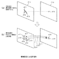
まず、図10(a)に示すように、前フレームF10内に選別された注目点d10が存在すると、その注目点d10を中心として、3つの動き先候補としての候補ベクトルを割り当てる。この候補ベクトルの割り当てを行うことで、現フレームF11内に、その候補ベクトルで示される動き先候補としての3つの参照点d11,d12,d13が得られる。 First, as shown in FIG. 10 (a), if a selected attention point d10 exists in the previous frame F10, candidate vectors as three motion destination candidates are assigned around the attention point d10. By assigning this candidate vector, three reference points d11, d12, d13 as motion destination candidates indicated by the candidate vector are obtained in the current frame F11.
このとき、図9のフローチャートのステップS32では、図10(b)に示すように、注目点d10を中心とした領域a10を、前フレームF10内に設定する。また、各参照点d11,d12,d13を中心とした領域a11,a12,a13を、現フレームF11内に設定する。
各領域a10,a11,a12,a13のサイズは等しいサイズとする。例えば、それぞれの領域を、垂直方向8画素×水平方向16画素の128画素の領域とする。
At this time, in step S32 of the flowchart of FIG. 9, as shown in FIG. 10B, an area a10 centered on the attention point d10 is set in the previous frame F10. Also, areas a11, a12, and a13 centered on the reference points d11, d12, and d13 are set in the current frame F11.
The areas a10, a11, a12, and a13 have the same size. For example, each area is a 128-pixel area of 8 pixels in the vertical direction and 16 pixels in the horizontal direction.
その上で、図9のフローチャートのステップS33で、注目点の周囲の領域a10内の各画素と、参照点の周囲の領域a11,a12,a13内の各画素との画素値が比較され、差分値が得られる。比較して得られた各画素位置の差分値は、絶対値化されて1つの領域ごとに加算されて、差分絶対値和が得られる。具体的には、図10(b)に示されるように、領域a10内の各画素と、領域a11内の各画素との差分値を得て、その差分値の絶対値を領域内で加算して差分値絶対値和Δα1を得る。また、領域a10内の各画素と、領域a12内の各画素との差分値を得て、その差分値の絶対値を領域内で加算して差分値絶対値和Δβ1を得る。また、領域a10内の各画素と、領域a13内の各画素との差分値を得て、その差分値の絶対値を領域内で加算して差分値絶対値和Δγ1を得る。 Then, in step S33 of the flowchart of FIG. 9, the pixel values of the pixels in the region a10 around the target point and the pixels in the regions a11, a12, a13 around the reference point are compared, and the difference is calculated. A value is obtained. The difference value of each pixel position obtained by the comparison is converted into an absolute value and added for each region to obtain a sum of absolute differences. Specifically, as shown in FIG. 10B, a difference value between each pixel in the region a10 and each pixel in the region a11 is obtained, and the absolute value of the difference value is added within the region. Thus, the difference value absolute value sum Δα1 is obtained. Also, a difference value between each pixel in the area a10 and each pixel in the area a12 is obtained, and the absolute value of the difference values is added in the area to obtain a difference value absolute value sum Δβ1. Also, a difference value between each pixel in the region a10 and each pixel in the region a13 is obtained, and the absolute value of the difference values is added in the region to obtain a difference value absolute value sum Δγ1.
そして、それぞれの差分絶対値和Δα1,Δβ1,Δγ1が比較されて、差分絶対値和が最小のものが、信頼度が高いものと判定される。図10(b)の例では、差分絶対値和Δα1が最小であったとする。このとき、注目点d10と参照点d11とを結ぶ動きベクトルが、このときの注目点d10についての候補ベクトルの中で、最も信頼度が高い候補ベクトルとする。注目点d10に対する最も信頼度が高い候補ベクトルが決まると、図9のフローチャートのステップS31で取り出した候補ベクトルの中で、該当する信頼度が高いと判断された候補ベクトルについての評価値を示すカウント値を+1する。この処理が図9のフローチャートのステップS34に相当する。 Then, the difference absolute value sums Δα1, Δβ1, and Δγ1 are compared, and the one having the smallest difference absolute value sum is determined to have high reliability. In the example of FIG. 10B, it is assumed that the difference absolute value sum Δα1 is minimum. At this time, the motion vector connecting the attention point d10 and the reference point d11 is the candidate vector having the highest reliability among the candidate vectors for the attention point d10 at this time. When the candidate vector with the highest reliability for the attention point d10 is determined, the count indicating the evaluation value for the candidate vector determined to have a high reliability among the candidate vectors extracted in step S31 of the flowchart of FIG. Add +1 to the value. This process corresponds to step S34 in the flowchart of FIG.
そして、このようにして信頼度を得る処理を、1フレーム内の選別された全ての注目画素について行い、最終的に得られた評価値のカウント値を使用して、図9のフローチャートのステップS31で取り出した複数の候補ベクトルそれぞれの信頼度を決定する。 Then, the process of obtaining the reliability in this way is performed for all the target pixels selected in one frame, and the count value of the evaluation value finally obtained is used to perform step S31 in the flowchart of FIG. The reliability of each of the plurality of candidate vectors taken out in is determined.
[評価値テーブルデータの信頼度を評価する処理例(下位と上位の階層の例)]
図9及び図10の例では、1つの注目点とその注目点から候補ベクトルで示される参照点について、その注目点及び参照点を中心とした1つの領域を設定して、それぞれの領域内の画素の差分絶対値和を判断するようにしたが、各注目点及び参照点に、複数の領域を設定してもよい。ここでは、複数の領域を設定する例として、上位階層での領域設定と、下位階層での領域設定を行う例について、図11及び図12を参照して説明する。
[Example of processing for evaluating the reliability of evaluation value table data (examples of lower and upper levels)]
In the example of FIG. 9 and FIG. 10, for one reference point and a reference point indicated by the candidate vector from the target point, one region centered on the target point and the reference point is set, Although the sum of absolute differences of pixels is determined, a plurality of regions may be set for each attention point and reference point. Here, as an example of setting a plurality of areas, an example of performing area setting in an upper hierarchy and area setting in a lower hierarchy will be described with reference to FIGS. 11 and 12.
まず図11のフローチャートを参照して、選別された注目画素についての候補ベクトルを、上位と下位の2つの階層で評価する処理例について説明する。この候補ベクトルを評価する処理は、図4に示した動きベクトル抽出部13で実行される。
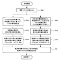
図11に従って説明すると、候補ベクトル信頼度評価部71では、頻度順ソート処理部62から、候補ベクトルを読み出す(ステップS41)。この候補ベクトルは、頻度順ソート処理部62で頻度順にソートされたものから抽出した候補ベクトルであり、1フレーム内の候補ベクトルの内で、頻度が高いものから上位の所定順位のものを候補ベクトルとする。例えば、ここでは1フレーム内で頻度が最も高いものから順に、20番目までの候補ベクトルを取り出す。以後は、下位階層での処理と上位階層での処理が並行して行われる。
First, with reference to the flowchart of FIG. 11, a description will be given of a processing example in which candidate vectors for the selected target pixel are evaluated in two upper and lower layers. The process of evaluating the candidate vector is executed by the motion
Referring to FIG. 11, the candidate vector
下位階層での処理としては、ステップS42に移り、候補ベクトル信頼度評価部71で、選別画素データメモリ73から供給された選別画素データで示された注目点の選別画素について、それぞれの注目画素を中心とした下位階層での所定の領域を設定する。そして、その注目画素から、ステップS41で取り出したそれぞれの候補ベクトルで示される動き先候補の参照点を設定する。例えば上述したように20番目までの候補ベクトルを取出した場合には、1つの注目点の選別画素について、20個の参照画素を設定することになる。
複数の参照画素が設定されると、それぞれの参照画素を中心とした下位階層での所定の領域を設定する。この参照画素を中心とした下位階層での領域のサイズは、注目画素を中心として設定した下位階層での領域のサイズと同じである。
そして、選別された注目画素を中心とした下位階層での領域の画素値と、それぞれの参照画素を中心とした下位階層での領域の画素値を、フレームメモリ74から取得する(ステップS42)。ここでの下位階層での領域としては、例えば垂直方向8画素×水平方向16画素の128画素の領域とする。
As processing in the lower hierarchy, the process proceeds to step S42, and the candidate vector
When a plurality of reference pixels are set, a predetermined area in a lower hierarchy centering on each reference pixel is set. The size of the area in the lower hierarchy centered on the reference pixel is the same as the area size in the lower hierarchy set around the target pixel.
Then, the pixel value of the area in the lower hierarchy centered on the selected pixel of interest and the pixel value of the area in the lower hierarchy centered on each reference pixel are acquired from the frame memory 74 (step S42). The area in the lower hierarchy here is, for example, a 128 pixel area of 8 pixels in the vertical direction × 16 pixels in the horizontal direction.
各領域内の画素値を取得すると、注目画素を中心とした領域内の各画素の画素値と、各参照画素を中心とした領域内の各画素の画素値との差分を取得し、その差分の領域毎の絶対値和を算出する(ステップS43)。この算出で、選別された注目画素からの候補ベクトルの内で、差分絶対値和が最小値となる参照画素の候補ベクトルを、下位階層で信頼度が高いベクトルと判断して、信頼度のカウント値を+1する(ステップS44)。 When the pixel value in each area is acquired, the difference between the pixel value of each pixel in the area centered on the target pixel and the pixel value of each pixel in the area centered on each reference pixel is acquired, and the difference The absolute value sum for each region is calculated (step S43). In this calculation, among the candidate vectors from the selected target pixel, the reference pixel candidate vector whose sum of absolute differences is the minimum value is determined as a highly reliable vector in the lower hierarchy, and the reliability is counted. The value is incremented by 1 (step S44).
また、上位階層での処理としては、ステップS45に移り、候補ベクトル信頼度評価部71で、選別画素データメモリ73から供給された選別画素データで示された注目点の選別画素について、それぞれの注目画素を中心とした上位階層での所定の領域を設定する。そして下位階層と同じ位置の各参照点に対しても、各参照画素を中心とした上位階層での所定の領域を設定する。この参照画素を中心とした上位階層での領域のサイズは、注目画素を中心として設定した上位階層での領域のサイズと同じである。ここでの上位階層での領域としては、例えば垂直方向24画素×水平方向48画素の1152画素の領域とする。但し、上位階層では、垂直方向3画素×水平方向3画素の単位ごとにブロック化し、ブロックごとに平均化した画素値を得る。
Further, as the processing in the upper hierarchy, the process proceeds to step S45, where the candidate
そして、注目画素を中心とした領域内のブロックの平均画素値と、各参照画素を中心とした領域内のブロックの平均画素値との差分を取得し、その差分の領域毎の絶対値和を算出する(ステップS46)。この算出で、選別された注目画素からの候補ベクトルの内で、差分絶対値和が最小値となる参照画素の候補ベクトルを、上位階層で信頼度が高いと判断して、信頼度のカウント値を+1する(ステップS47)。 Then, the difference between the average pixel value of the block in the area centered on the target pixel and the average pixel value of the block in the area centered on each reference pixel is acquired, and the absolute value sum for each area of the difference is obtained. Calculate (step S46). In this calculation, among the candidate vectors from the selected target pixel, the reference pixel candidate vector having the smallest sum of absolute differences is determined to have high reliability in the upper layer, and the reliability count value Is incremented by 1 (step S47).
そして、1フレーム内の全ての選別された注目画素について、同様の下位階層での候補ベクトルの信頼性の評価と、上位階層での候補ベクトルの信頼性の評価をした後、候補ベクトルの信頼度を決定する(ステップS48)。 Then, for all selected target pixels in one frame, after evaluating the reliability of the candidate vector in the same lower layer and the reliability of the candidate vector in the upper layer, the reliability of the candidate vector Is determined (step S48).
[評価値テーブルデータの信頼度を評価する原理の説明(下位と上位の階層の例)]
次に、図12を参照して、図11のフローチャートの処理で実行される、下位階層と上位階層を使って、評価値テーブルデータの信頼度を評価する処理で、信頼度が判定される原理について説明する。この例でも説明を簡単にするために、頻度の高いものから3つの候補ベクトルを取り出したものとする。なお、図12において、下位階層での処理については、図10で説明した処理と全く同じである。
まず、図12(a)に示すように、前フレームF10内に選別された注目点d10が存在すると、その注目点d10を中心として、3つの動き先候補としての候補ベクトルを割り当てる。この候補ベクトルの割り当てを行うことで、現フレームF11内に、その候補ベクトルで示される動き先候補としての3つの参照点d11,d12,d13が得られる。この図12(a)の状態は、図10(a)の状態と同じである。
[Description of the principle for evaluating the reliability of evaluation value table data (examples of lower and upper levels)]
Next, referring to FIG. 12, the principle of determining the reliability in the process of evaluating the reliability of the evaluation value table data using the lower hierarchy and the upper hierarchy executed in the process of the flowchart of FIG. Will be described. In order to simplify the explanation also in this example, it is assumed that three candidate vectors are extracted from the frequently used ones. In FIG. 12, the processing in the lower hierarchy is exactly the same as the processing described in FIG.
First, as shown in FIG. 12 (a), if a selected attention point d10 exists in the previous frame F10, candidate vectors as three motion destination candidates are assigned around the attention point d10. By assigning this candidate vector, three reference points d11, d12, d13 as motion destination candidates indicated by the candidate vector are obtained in the current frame F11. The state of FIG. 12A is the same as the state of FIG.
そして、図11のフローチャートのステップS42の下位階層の処理では、図12(b)に示すように、注目点d10を中心とした下位階層での領域a10を、前フレームF10内に設定する。また、各参照点d11,d12,d13を中心とした下位階層での領域a11,a12,a13を、現フレームF11内に設定する。
下位階層での各領域a10,a11,a12,a13のサイズは等しいサイズとする。例えば、それぞれの領域を、垂直方向8画素×水平方向16画素の128画素の領域とする。
Then, in the processing of the lower hierarchy in step S42 in the flowchart of FIG. 11, as shown in FIG. 12B, the area a10 in the lower hierarchy centered on the attention point d10 is set in the previous frame F10. In addition, areas a11, a12, and a13 in the lower hierarchy centered on the reference points d11, d12, and d13 are set in the current frame F11.
The size of each area | region a10, a11, a12, a13 in a lower hierarchy shall be the same size. For example, each area is a 128-pixel area of 8 pixels in the vertical direction and 16 pixels in the horizontal direction.
図11のフローチャートのステップS45の上位階層の処理では、図12(b)に示すように、注目点d10を中心とした上位階層での領域A10を、前フレームF10内に設定する。また、各参照点d11,d12,d13を中心とした上位階層での領域A11,A12,A13を、現フレームF11内に設定する。 In the process of the upper layer in step S45 of the flowchart of FIG. 11, as shown in FIG. 12B, the region A10 in the upper layer with the attention point d10 as the center is set in the previous frame F10. In addition, areas A11, A12, and A13 in the upper hierarchy centered on the reference points d11, d12, and d13 are set in the current frame F11.
上位階層については、図13に示すようにブロック化を行う。即ち、図13(a)に示すように、注目点d10又は参照点d11について、その周辺に領域を設定する際に、垂直方向3画素×水平方向3画素の9画素単位でのブロックB0,B1,B2,B3,B4・・・を設定する。各ブロック内の9画素の画素値(輝度値)は、平均化して、ブロック単位で平均画素値を持つようにする。 As shown in FIG. 13, the upper layer is blocked. That is, as shown in FIG. 13A, when an area is set around the attention point d10 or the reference point d11, blocks B0 and B1 in units of nine pixels of 3 pixels in the vertical direction × 3 pixels in the horizontal direction. , B2, B3, B4... Are set. The pixel values (luminance values) of nine pixels in each block are averaged to have an average pixel value in units of blocks.
そして、図13(b)に示すように、その各ブロックを、垂直方向8ブロック×水平方向16ブロックの128ブロック用意する。この128ブロックの平均画素値の絶対値和差分を算出する。 Then, as shown in FIG. 13B, 128 blocks of 8 blocks in the vertical direction × 16 blocks in the horizontal direction are prepared for each block. The absolute value sum difference of the average pixel values of the 128 blocks is calculated.
各領域A10,A11,A12,A13は、それぞれ等しいサイズであり、また、下位階層での領域a10,a11,a12,a13よりも大きな領域としてある。例えば、それぞれの領域を、垂直方向24画素×水平方向48画素の1152画素の領域とする。 The areas A10, A11, A12, and A13 have the same size, and are larger than the areas a10, a11, a12, and a13 in the lower hierarchy. For example, each region is a region of 1152 pixels of 24 pixels in the vertical direction × 48 pixels in the horizontal direction.
図12(b)の説明に戻ると、図11のフローチャートのステップS43の下位階層での処理で、注目点の周囲の領域a10内の各画素と、参照点の周囲の領域a11,a12,a13内の各画素との画素値が比較され、差分値が得られる。比較して得られた各画素位置の差分値は、絶対値化されて1つの領域ごとに加算されて、差分絶対値和が得られる。具体的には、図10(b)に示されるように、領域a10内の各画素と、領域a11内の各画素との差分値を得て、その差分値の絶対値を領域内で加算して、下位階層での差分値絶対値和Δα1を得る。また、領域a10内の各画素と、領域a12内の各画素との差分値を得て、その差分値の絶対値を領域内で加算して、下位階層での差分値絶対値和Δβ1を得る。また、領域a10内の各画素と、領域a13内の各画素との差分値を得て、その差分値の絶対値を領域内で加算して、下位階層での差分値絶対値和Δγ1を得る。 Returning to the description of FIG. 12B, each pixel in the area a <b> 10 around the target point and the areas a <b> 11, a <b> 12, a <b> 13 around the reference point in the processing in the lower layer of step S <b> 43 in the flowchart of FIG. 11. The pixel value with each of the pixels is compared, and a difference value is obtained. The difference value of each pixel position obtained by the comparison is converted into an absolute value and added for each region to obtain a sum of absolute differences. Specifically, as shown in FIG. 10B, a difference value between each pixel in the region a10 and each pixel in the region a11 is obtained, and the absolute value of the difference value is added within the region. Thus, the difference value absolute value sum Δα1 in the lower hierarchy is obtained. Further, a difference value between each pixel in the region a10 and each pixel in the region a12 is obtained, and the absolute value of the difference value is added in the region to obtain a difference value absolute value sum Δβ1 in the lower hierarchy. . Further, a difference value between each pixel in the region a10 and each pixel in the region a13 is obtained, and the absolute value of the difference value is added in the region to obtain a difference value absolute value sum Δγ1 in the lower hierarchy. .
同様に、図11のフローチャートのステップS46の上位階層での処理で、注目点の周囲の領域A10内の各画素と、参照点の周囲の領域A11,A12,A13内の各画素との画素値が比較され、差分値が得られる。比較して得られた各画素位置の差分値は、絶対値化されて1つの領域ごとに加算されて、差分絶対値和が得られる。具体的には、図12(b)に示されるように、領域A10内の各画素と、領域A11内の各画素との差分値を得て、その差分値の絶対値を領域内で加算して、上位階層での差分値絶対値和Δα2を得る。また、領域A10内の各画素と、領域A12内の各画素との差分値を得て、その差分値の絶対値を領域内で加算して、上位階層での差分値絶対値和Δβ2を得る。また、領域A10内の各画素と、領域A13内の各画素との差分値を得て、その差分値の絶対値を領域内で加算して、上位階層での差分値絶対値和Δγ2を得る。 Similarly, the pixel values of the pixels in the region A10 around the target point and the pixels in the regions A11, A12, A13 around the reference point in the processing in the upper layer of step S46 in the flowchart of FIG. Are compared to obtain a difference value. The difference value of each pixel position obtained by the comparison is converted into an absolute value and added for each region to obtain a sum of absolute differences. Specifically, as shown in FIG. 12B, the difference value between each pixel in the area A10 and each pixel in the area A11 is obtained, and the absolute value of the difference value is added within the area. Thus, the difference value absolute value sum Δα2 in the upper layer is obtained. Also, a difference value between each pixel in the region A10 and each pixel in the region A12 is obtained, and the absolute value of the difference value is added in the region to obtain a difference value absolute value sum Δβ2 in the upper layer. . Further, a difference value between each pixel in the region A10 and each pixel in the region A13 is obtained, and the absolute value of the difference value is added in the region to obtain a difference value absolute value sum Δγ2 in the upper layer. .
そして、下位階層でのそれぞれの差分絶対値和Δα1,Δβ1,Δγ1が比較されて、差分絶対値和が最小のものが、下位階層で信頼度が高いものと判定される。図12(b)の例では、差分絶対値和Δα1が下位階層で最小であったとする。このとき、下位階層での判断処理で、注目点d10と参照点d11とを結ぶ動きベクトルが、このときの選別された注目点d10についての候補ベクトルの中で、最も信頼度が高い候補ベクトルとする。
下位階層で注目点d10に対して信頼度が高い候補ベクトルが決まると、図11のフローチャートのステップS41で得た候補ベクトルの中で、該当する信頼度が高いと判断された候補ベクトルについての下位階層での評価値を示すカウント値を+1する。この処理が図11のフローチャートのステップS44に相当する。
同様に、上位階層でのそれぞれの差分絶対値和Δα2,Δβ2,Δγ2が比較されて、差分絶対値和が最小のものが、上位階層で信頼度が高いものと判定される。図12(b)の例では、差分絶対値和Δα2が上位階層で最小であったとする。このとき、上位階層での判断処理で、注目点d10と参照点d11とを結ぶ動きベクトルが、このときの選別された注目点d10についての候補ベクトルの中で、最も信頼度が高い候補ベクトルとする。
上位階層で注目点d10に対して信頼度が高い候補ベクトルが決まると、図11のフローチャートのステップS41で得た候補ベクトルの中で、該当する信頼度が高いと判断された候補ベクトルについての上位階層での評価値を示すカウント値を+1する。この処理が図11のフローチャートのステップS47に相当する。
Then, the difference absolute value sums Δα1, Δβ1, and Δγ1 in the lower layer are compared, and the one having the smallest difference absolute value sum is determined to have high reliability in the lower layer. In the example of FIG. 12B, it is assumed that the difference absolute value sum Δα1 is the smallest in the lower hierarchy. At this time, in the determination process in the lower hierarchy, the motion vector connecting the attention point d10 and the reference point d11 is the candidate vector having the highest reliability among the candidate vectors for the attention point d10 selected at this time. To do.
When a candidate vector having high reliability is determined for the attention point d10 in the lower hierarchy, among the candidate vectors obtained in step S41 of the flowchart of FIG. The count value indicating the evaluation value in the hierarchy is incremented by one. This process corresponds to step S44 in the flowchart of FIG.
Similarly, the difference absolute value sums Δα2, Δβ2, and Δγ2 in the upper layer are compared, and the one having the smallest difference absolute value sum is determined to have high reliability in the upper layer. In the example of FIG. 12B, it is assumed that the difference absolute value sum Δα2 is the smallest in the upper hierarchy. At this time, in the determination process in the upper layer, the motion vector connecting the attention point d10 and the reference point d11 is the candidate vector having the highest reliability among the candidate vectors for the attention point d10 selected at this time. To do.
When a candidate vector with high reliability is determined for the attention point d10 in the upper hierarchy, among the candidate vectors obtained in step S41 of the flowchart of FIG. The count value indicating the evaluation value in the hierarchy is incremented by one. This process corresponds to step S47 in the flowchart of FIG.
そして、このようにして信頼度を得る処理を、1フレーム内の選別された全ての注目画素について行い、最終的に得られた評価値のカウント値を使用して、図9のフローチャートのステップS31で取り出した複数の候補ベクトルそれぞれの信頼度を決定する。
なお、図12の例では、下位階層での処理で、最も信頼度が高いと判断される候補ベクトルと、上位階層での処理で、最も信頼度が高いと判断される候補ベクトルとは同じベクトルとしたが、必ずしも最も信頼度が高いと判断される候補ベクトルが、上位と下位で同じになるとは限らない。
Then, the process of obtaining the reliability in this way is performed for all the target pixels selected in one frame, and the count value of the evaluation value finally obtained is used to perform step S31 in the flowchart of FIG. The reliability of each of the plurality of candidate vectors taken out in is determined.
In the example of FIG. 12, the candidate vector that is determined to have the highest reliability in the processing at the lower layer and the candidate vector that is determined to have the highest reliability in the processing at the upper layer are the same vector. However, the candidate vectors that are determined to have the highest reliability are not necessarily the same at the upper and lower levels.
このようにして得られた下位階層での候補ベクトルの信頼度についての評価値(カウント値)と、上位階層での候補ベクトルの信頼度についての評価値(カウント値)を使用して、1フレーム内の画面全体の候補ベクトルの中から信頼度の高いものを決定する。 Using the evaluation value (count value) for the reliability of the candidate vector in the lower layer obtained in this way and the evaluation value (count value) for the reliability of the candidate vector in the upper layer, one frame Among the candidate vectors of the entire screen, a highly reliable one is determined.
なお、図11のフローチャートでは、下位階層と上位階層との双方で処理を行う例について説明したが、上位階層の領域だけを設定して、その上位階層で得たブロックの平均画素値の差分の絶対値の和から、候補ベクトルの信頼性を評価してもよい。 In the flowchart of FIG. 11, the example in which processing is performed in both the lower hierarchy and the upper hierarchy has been described. However, only the upper hierarchy area is set, and the difference between the average pixel values of the blocks obtained in the upper hierarchy is changed. You may evaluate the reliability of a candidate vector from the sum of an absolute value.
[下位階層と上位階層の説明]
図12で示した候補ベクトルの信頼性を評価する処理例を、下位階層と上位階層とで個別に示すと、図14及び図15に示す状態となる。
即ち、下位階層では、図14に示すように、選別された注目画素d10と、その注目画素から候補ベクトルで示された参照画素d11,d12,d13を中心とした8画素×16画素の領域a10,a11,a12,・・・が設定される。そして、それぞれの領域内の画素の絶対値差分和が得られ、比較される。
上位階層では、図15に示すように、注目画素d10と、その注目画素から候補ベクトルで示された参照画素d11,d12,d13を中心とした24画素×48画素の領域A10,A11,A12,・・・が設定され、3画素×3画素のブロック単位とされる。そして、それぞれの領域のブロック平均の絶対値差分和が得られ、比較される。
このようにして、評価値テーブルで示された動きベクトルの候補について、信頼性を示すカウント値が得られ、その信頼性を示すカウント値に基づいて、候補ベクトルが絞られる。
[Explanation of lower and upper layers]
When the processing example for evaluating the reliability of the candidate vector shown in FIG. 12 is individually shown in the lower hierarchy and the upper hierarchy, the state shown in FIGS. 14 and 15 is obtained.
That is, in the lower layer, as shown in FIG. 14, a region a10 of 8 × 16 pixels centered on the selected target pixel d10 and the reference pixels d11, d12, d13 indicated by the candidate vectors from the target pixel. , A11, a12,... Are set. Then, absolute value difference sums of pixels in the respective regions are obtained and compared.
In the upper layer, as shown in FIG. 15, regions A10, A11, A12, 24 pixels × 48 pixels centered on the target pixel d10 and the reference pixels d11, d12, d13 indicated by the candidate vectors from the target pixel. ... Are set, and a block unit of 3 pixels × 3 pixels is set. Then, an absolute value difference sum of block averages of the respective areas is obtained and compared.
In this manner, a count value indicating reliability is obtained for the motion vector candidates shown in the evaluation value table, and the candidate vectors are narrowed down based on the count value indicating the reliability.
[評価値テーブルと評価結果の例]
ここで、評価値テーブルで得られた候補ベクトルと評価結果の例について、図16〜図20を参照して説明する。
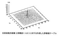
まず、1フレームの全画面に対して検出した評価値テーブルの例を、図16に示す。この図16は、画面全体が1つの方向に動いている状態の例である。この例では、1フレーム間で、画面全体として、水平方向(Vx)に−3(つまり3画素の動き)、垂直方向(Vy)に0(つまり動きなし)の動きがあった例を示している。
この例では、評価値テーブルデータとして、正解の動きベクトル位置である(−3,0)の位置にピークがあるデータとなっているが、その他のベクトル位置についても、ある程度の数の動きベクトルが候補として残っている。
[Example of evaluation value table and evaluation results]
Here, examples of candidate vectors and evaluation results obtained from the evaluation value table will be described with reference to FIGS.
First, an example of the evaluation value table detected for the entire screen of one frame is shown in FIG. FIG. 16 shows an example of a state where the entire screen is moving in one direction. In this example, the entire screen has a movement of -3 (that is, movement of 3 pixels) in the horizontal direction (Vx) and 0 (that is, no movement) in the vertical direction (Vy), as shown in FIG. Yes.
In this example, the evaluation value table data is data having a peak at the position (-3, 0), which is the correct motion vector position, but a certain number of motion vectors are also present at other vector positions. It remains as a candidate.
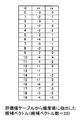
この図16に示す状態の評価値テーブル内の動きベクトルを、頻度のカウント値の順に抽出した候補ベクトルが、図17に示したものである。この図17の例では、頻度が高い順に20番目までを抽出してあり、頻度が高いものから番号(id)を0,1,2,・・・,19と付与してある。 FIG. 17 shows candidate vectors obtained by extracting motion vectors in the evaluation value table in the state shown in FIG. 16 in order of frequency count values. In the example of FIG. 17, up to the 20th are extracted in descending order of frequency, and numbers (id) are assigned as 0, 1, 2,.
図18は、この図17の頻度20番目までの候補ベクトルの内で、選別された注目画素についての下位階層での領域の絶対値差分和の判断で、信頼性が高いとなってカウントされた結果の数値を示したものである。この下位階層での処理では、カウント値が1以上である候補ベクトルの内で、最も頻度が低い候補ベクトルがid=9である。但し、id=9より頻度が高い候補ベクトルでも、id=4とid=6は、カウント値が0である。id=9よりも頻度の低い候補ベクトルは、全てカウント値が0で、どの選別画素でも信頼性が高くないと判断されたものである。
この例では、id=0からid=9までの頻度順で10番までの座標位置の候補ベクトルを、最終的な候補ベクトルとして選ぶ。このようにして選定された候補ベクトルのデータを図1に示した動きベクトル決定部14に送り、最終的な動きベクトルが決定される。
この図18の例は、下位階層だけで判断しているので、図9のフローチャートの処理を実行したものに相当する。
FIG. 18 is counted with high reliability in the determination of the sum of absolute value differences of the regions in the lower hierarchy for the selected target pixel among the candidate vectors up to the 20th frequency in FIG. The numerical value of the result is shown. In the processing in the lower hierarchy, id = 9 is the least frequent candidate vector among candidate vectors having a count value of 1 or more. However, even if the candidate vector has a higher frequency than id = 9, the count value is 0 for id = 4 and id = 6. Candidate vectors with a frequency lower than id = 9 are all count values of 0, and any selected pixel is determined not to have high reliability.
In this example, candidate vectors at coordinate positions up to 10 in the frequency order from id = 0 to id = 9 are selected as final candidate vectors. The candidate vector data selected in this way is sent to the motion
The example in FIG. 18 corresponds to the processing in the flowchart in FIG. 9 because the determination is made only in the lower hierarchy.
図19は、図17の頻度20番目までの候補ベクトルの内で、選別された注目画素についての上位階層での領域の絶対値差分和の判断で、信頼性が高いとなってカウントされた結果の数値を示したものである。この上位階層での処理では、id=0と、id=3と、id=7との3つの座標位置の候補ベクトルに対して、カウント値があり、それ以下の候補ベクトルは、全てカウント値が0で、どの選別画素でも信頼性が高くないと判断されたものである。
従って、この例では、id=0と、id=3と、id=7との3つの座標位置の候補ベクトルを、最終的な候補ベクトルとして選ぶ。このようにして選定された候補ベクトルのデータを図1に示した動きベクトル決定部14に送り、最終的な動きベクトルが決定される。
この図19の例は、上位階層だけで判断しているので、図11のフローチャートの一部の処理(ステップS41,S45,S46,S47,S48の処理)を実行したものに相当する。
FIG. 19 shows the result of counting with high reliability in the determination of the sum of absolute value differences of the region in the upper hierarchy for the selected target pixel among the candidate vectors up to the 20th frequency in FIG. The numerical value of is shown. In the processing in this higher layer, there are count values for candidate vectors at three coordinate positions of id = 0, id = 3, and id = 7, and all candidate vectors below that have count values. At 0, it was determined that any selected pixel is not highly reliable.
Therefore, in this example, candidate vectors at three coordinate positions of id = 0, id = 3, and id = 7 are selected as final candidate vectors. The candidate vector data selected in this way is sent to the motion
Since the example of FIG. 19 is determined only by the upper hierarchy, it corresponds to a case where a part of the processing of the flowchart of FIG. 11 (processing of steps S41, S45, S46, S47, and S48) is executed.
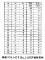
図20は、下位階層での判断で信頼性が高いとなってカウントされた結果の数値と、上位階層での判断で信頼性が高いとなってカウントされた結果の数値とを並べて示したものであり、図18と図19を合わせたものである。この図20の例は、図11のフローチャートの処理を実行したものに相当する。
この図20に示した候補ベクトルから、それぞれのカウント値の状態を判断して、所定の頻度順以上のカウント値の候補ベクトルを、候補ベクトルとして抽出して、動きベクトル決定部に送る。
FIG. 20 shows the numerical values of the results counted with high reliability in the determination in the lower hierarchy and the numerical values of the results counted with high reliability in the determination in the upper hierarchy. FIG. 18 and FIG. 19 are combined. The example of FIG. 20 corresponds to the example in which the process of the flowchart of FIG. 11 is executed.
The status of each count value is determined from the candidate vectors shown in FIG. 20, and candidate vectors with count values in a predetermined frequency order or higher are extracted as candidate vectors and sent to the motion vector determination unit.
下位階層だけから判断を行う場合と、上位階層だけから判断を行う場合と、下位と上位の2つの階層から判断を行う場合は、実際の画像の状態によってどれを選ぶのが好ましいか異なる。即ち、比較的小さな動きが多い画像の場合には、下位階層だけを使って、良好に候補ベクトルの信頼性を評価して、候補を絞ることが可能になっている。また、比較的大きな動きが多い画像の場合には、上位階層だけを使って、良好に候補ベクトルの信頼性を評価して、候補を絞ることが可能になっている。
さらに、下位階層と上位階層を組み合わせることで、比較的小さな動きと比較的大きな動きのいずれにも対処できるようになる。但し、下位階層と上位階層とを組み合わせた場合には、2つの階層で得た2種類のカウント値から、最終的にどこまでを候補とするのかの判断処理が必要になる。
When the determination is made only from the lower layer, the determination is performed only from the upper layer, and the determination is performed from the lower and upper layers, which one is preferably selected depends on the actual image state. That is, in the case of an image with a relatively small amount of motion, it is possible to narrow down candidates by evaluating the reliability of candidate vectors satisfactorily using only the lower hierarchy. In addition, in the case of an image with a relatively large amount of motion, it is possible to narrow down candidates by evaluating the reliability of candidate vectors satisfactorily using only the upper layer.
Furthermore, by combining the lower layer and the upper layer, it becomes possible to cope with both a relatively small movement and a relatively large movement. However, in the case where the lower hierarchy and the upper hierarchy are combined, it is necessary to determine the final candidate from the two types of count values obtained in the two hierarchies.
このようにして本実施の形態の処理構成とすることで、画素選別データによって絞られた評価値テーブルのデータに対して、信頼性を評価でき、最終的に動きベクトルを決定する処理が、良好に行える。具体的には、評価されたカウント値に基づいて信頼性が高いと判断されたベクトルの数をある程度反映して、最終的に1フレームの画像内の動きベクトル数を決定するようにしたことで、1画像中に複数の動きがある場合の動きベクトル検出を良好に行える。従来、1フレーム内の動きベクトル数を、経験的に求まる一定の値に制限して決定していた場合に比べて、実際の画像状態に応じて適応的に設定でき、特に動きの変化が多い画像に好適な動きベクトル検出が行えるようになる。 In this way, with the processing configuration of the present embodiment, the reliability of the evaluation value table data narrowed down by the pixel selection data can be evaluated, and the process of finally determining the motion vector is good. Can be done. Specifically, the number of motion vectors in one frame image is finally determined by reflecting to some extent the number of vectors determined to be highly reliable based on the evaluated count value. Motion vector detection can be performed satisfactorily when there are a plurality of movements in one image. Conventionally, the number of motion vectors in one frame can be set adaptively according to the actual image state, compared with the case where the number of motion vectors is determined by limiting to a fixed value determined empirically. Motion vector detection suitable for an image can be performed.
[動きベクトル決定部の構成及び動作例]
次に、図1の構成に示した動きベクトル検出装置での、動きベクトル決定部14の構成及び動作の例について、図21〜図23を参照して説明する。
図21は、図1の動きベクトル決定部14の構成例を示したものである。動きベクトル決定部14は、1フレーム内のそれぞれの画素に、前段の動きベクトル抽出部13から供給される複数の候補ベクトルのいずれかを割当てる処理を行うものである。
この例では、それぞれの画素位置を注目点としたとき、その注目点の周囲に、所定の画素数で構成される領域である固定ブロックを設定して、動きベクトルを判定する例である。
[Configuration and operation example of motion vector determination unit]
Next, an example of the configuration and operation of the motion
FIG. 21 shows a configuration example of the motion
In this example, when each pixel position is an attention point, a fixed block that is an area composed of a predetermined number of pixels is set around the attention point to determine a motion vector.
図21に従って構成を説明すると、動きベクトル割当て部14の入力端子14aには、動きベクトルの候補のデータと、その候補ベクトルについての画像信号とが供給される。画像信号は、フレームメモリである参照点メモリ211に供給されて1フレーム記憶される。そして、参照点メモリ211に記憶された画像信号が、フレーム期間ごとに注目点メモリ212に移される。従って、参照点メモリ211に記憶される画像信号と、注目点メモリ212に記憶される画像信号とは、常に1フレーム期間ずれた信号である。
The configuration will be described with reference to FIG. 21. The motion vector candidate data and the image signal for the candidate vector are supplied to the input terminal 14a of the motion
そして、注目点メモリ212に記憶された画像信号から、注目点を中心として決められたサイズの固定ブロックの画素信号をデータ読出し部213に読み出す。同様に、参照点メモリ211に記憶された画像信号から、参照点を中心とした決められたサイズの固定ブロックの画素信号をデータ読出し部213に読み出す。このデータ読出し部213で読出される注目点と参照点の画素位置(注目画素と参照画素)は、動きベクトル抽出部13(図1)から供給された候補ベクトルのデータから、データ読出し部213で判断される。即ち、例えば候補ベクトルが10個ある場合には、注目点からその10個の候補ベクトルで動いた先の10個の参照点が判断されることになる。
Then, from the image signal stored in the
そして、データ読出し部213で読出された、注目点を中心とした固定領域の画素信号と、参照点を中心とした固定領域の画素信号とを、評価値算出部214に供給して、両固定領域の画素信号の差分が検出される。このようにして、評価値算出部214では、現在評価中の注目点と候補ベクトルで接続された全ての参照点の固定領域の画素信号を判断し、注目点を中心とした固定領域の画素信号と比較する。
そして、評価値算出部214では、比較の結果で、注目点を中心とした固定領域の画素信号と最も類似した固定領域を持った参照点を選定する。
選定された参照点と注目点とを結ぶ候補ベクトルのデータは、ベクトル決定部215に送る。ベクトル決定部215では、該当する候補ベクトルを、注目点からの動きベクトルに割り当てる決定処理を行い、その決定した候補ベクトルを出力端子215から出力させる。
Then, the pixel signal of the fixed region centered on the point of interest and the pixel signal of the fixed region centered on the reference point read by the
Then, the evaluation
The candidate vector data connecting the selected reference point and the point of interest is sent to the
図22のフローチャートは、この図21のベクトル決定(割当て)処理動作例を示したフローチャートである。
図22に従って順に説明すると、まず評価値テーブルのデータに基づいて候補ベクトルが読出される(ステップS121)。読出された候補ベクトルについての注目点の座標位置を判断し、その位置の画素(注目画素)とその周辺画素で構成される固定ブロックの画素を注目点メモリ52から読出す(ステップS122)。また、読出された候補ベクトルについての参照点の座標位置を判断し、その位置の画素(参照画素)とその周辺画素で構成される固定ブロックの画素を参照点メモリ211から読出す(ステップS123)。
そして、それぞれの固定ブロック内の画素レベル(画素値:ここでは輝度値)の差分の絶対値和を算出する(ステップS124)。ここまでの処理を、現在の注目点についての全ての候補ベクトルで示された参照点について行う。
そして、参照点について設定した固定ブロックについて算出した差分の絶対値和の内で、注目点について設定した固定ブロックの差分の絶対値和と比較して、差が最小になる参照点を探す。この処理で、差が最小になる参照点を判断すると、その判断された参照点と注目点を結ぶ候補ベクトルを、注目点についての動きベクトルとして割り当てることを決定する(ステップS125)。
The flowchart of FIG. 22 is a flowchart showing an example of the vector determination (assignment) processing operation of FIG.
When described in order according to FIG. 22, first, candidate vectors are read based on the data of the evaluation value table (step S121). The coordinate position of the target point with respect to the read candidate vector is determined, and the pixel of the fixed block composed of the pixel at the position (target pixel) and its peripheral pixels is read from the target point memory 52 (step S122). Also, the coordinate position of the reference point for the read candidate vector is determined, and the pixel of the fixed block composed of the pixel (reference pixel) at that position and its surrounding pixels is read from the reference point memory 211 (step S123). .
Then, the absolute value sum of the differences between the pixel levels (pixel value: luminance value here) in each fixed block is calculated (step S124). The processing so far is performed for the reference points indicated by all candidate vectors for the current attention point.
Then, the absolute value sum of the differences calculated for the fixed block set for the reference point is compared with the absolute value sum of the differences of the fixed block set for the attention point, and the reference point that minimizes the difference is searched. If a reference point that minimizes the difference is determined in this process, it is determined to assign a candidate vector that connects the determined reference point and the target point as a motion vector for the target point (step S125).
図23は、この図21の構成及び図22のフローチャートでの処理状態の概要を示した図である。
この例では、フレームF10(注目フレーム)に注目点d10が存在し、その時間軸上の次のフレームF11(参照フレーム)内との間で、複数の候補ベクトルV11,V12が存在しているとする。フレームF11には、候補ベクトルV11,V12で注目点d10と結ばれた参照点d11,d12が存在している。
このような図27の状態を想定すると、図23のステップS122では、フレームF10内で、注目点d10の中心にして固定した所定画素数の固定ブロックB10が設定され、その固定ブロックB10内の画素値の差分の絶対値和が算出される。同様に、図23のステップS123では、フレームF11内で、参照点d11,d12の中心にして固定した所定画素数の固定ブロックB11,B12が設定され、その固定ブロックB11,B12内の画素値の差分の絶対値和が、それぞれ個別に算出される。
FIG. 23 is a diagram showing an outline of the processing state in the configuration of FIG. 21 and the flowchart of FIG.
In this example, the point of interest d10 exists in the frame F10 (frame of interest), and a plurality of candidate vectors V11, V12 exist between the next frame F11 (reference frame) on the time axis. To do. In the frame F11, there are reference points d11 and d12 connected to the point of interest d10 by candidate vectors V11 and V12.
Assuming such a state of FIG. 27, in step S122 of FIG. 23, a fixed block B10 having a predetermined number of pixels fixed at the center of the point of interest d10 is set in the frame F10, and the pixels in the fixed block B10 are set. The absolute value sum of the difference between the values is calculated. Similarly, in step S123 of FIG. 23, fixed blocks B11 and B12 having a predetermined number of pixels fixed at the center of the reference points d11 and d12 are set in the frame F11, and the pixel values in the fixed blocks B11 and B12 are set. The sum of absolute values of the differences is calculated individually.
そして、固定ブロックB11の差分の絶対値和と、固定ブロックB12の差分の絶対値和の内で、固定ブロックB10の差分の絶対値和に近い方がいずれか比較される。この比較で、例えば固定ブロックB11の差分の絶対値和の方が、固定ブロックB10の差分の絶対値和に近いと判断すると、その固定ブロックB11の中心の参照点d11と、注目点d10とを結ぶ候補ベクトルV11が選択される。この選択された候補ベクトルV11を、注目点d10の動きベクトルとして割り当てる。
なお、図23では説明を簡単にするために候補ベクトルを2つとして説明したが、実際には1つの注目点に対してより多くの候補ベクトルが存在することがある。また、説明を簡単にするために1つの注目点だけを示してあるが、実際には、1フレーム内の全ての画素又は代表となる複数の画素が、このような注目点となる。
Then, of the absolute value sum of the differences of the fixed block B11 and the absolute value sum of the differences of the fixed block B12, the one closer to the absolute value sum of the differences of the fixed block B10 is compared. In this comparison, for example, if it is determined that the sum of absolute values of the differences in the fixed block B11 is closer to the sum of absolute values of the differences in the fixed block B10, the reference point d11 at the center of the fixed block B11 and the point of interest d10 are A candidate vector V11 to be connected is selected. The selected candidate vector V11 is assigned as a motion vector of the attention point d10.
In FIG. 23, two candidate vectors are described for the sake of simplicity, but in reality, more candidate vectors may exist for one attention point. Further, for the sake of simplicity, only one point of interest is shown, but in reality, all pixels in one frame or a plurality of representative pixels are such points of interest.
このようにして候補ベクトルから選定するベクトルを決定する処理を行うことで、注目点の周囲の画素の状態と、参照点の周囲の画素の状態とが、近いものが選定されることになり、それぞれの画素に割り当てる動きベクトルの選定が、良好に行える。 By performing the process of determining the vector to be selected from the candidate vectors in this way, a state in which the state of the pixels around the attention point and the state of the pixels around the reference point are close is selected. The motion vector to be assigned to each pixel can be favorably selected.
[実施の形態の変形例の説明]
なお、上述した実施の形態では、注目点の選定処理については具体的に説明しなかったが、例えば1フレーム内の全ての画素を順に注目点として選定して、それぞれの画素について動きベクトルを検出させる構成としてもよい。或いは、1フレーム内で代表となる画素を注目点として選び出し、その選び出した画素についての動きベクトルを検出させる場合にも適用してもよい。
また、注目点に対する参照点の選定処理についても、図6などに図示したサーチエリアSAは一例であり、様々なサーチエリアの選定を適用することができる。
[Description of Modification of Embodiment]
In the above-described embodiment, the attention point selection processing has not been specifically described. For example, all pixels in one frame are sequentially selected as attention points, and a motion vector is detected for each pixel. A configuration may be adopted. Alternatively, the present invention may be applied to a case where a representative pixel within one frame is selected as a point of interest, and a motion vector for the selected pixel is detected.
Further, for the reference point selection process for the attention point, the search area SA illustrated in FIG. 6 and the like is an example, and various search area selections can be applied.
また、上述した実施の形態では、図18〜図20に示した候補ベクトルの評価結果から、最終的な候補ベクトルを選択する処理としては、信頼性があると判断される候補ベクトルが存在しない範囲、即ち図18などでカウント値として0が続く範囲を除外した。そして、それよりも上位の範囲を選択する処理を行うようにしたが、カウント値が0以外の個所の候補ベクトルについても除去するようにしてもよい。例えば、図18の例では、上位10番目まで候補ベクトルとするようにしたが、カウント値が1桁などの少ない数の候補ベクトルについては除外するようにしてもよい。 Further, in the above-described embodiment, as a process of selecting a final candidate vector from the candidate vector evaluation results illustrated in FIGS. 18 to 20, a range in which there is no candidate vector determined to be reliable exists. That is, the range where 0 is counted as the count value in FIG. Then, the process of selecting a higher range is performed, but candidate vectors other than the count value of 0 may be removed. For example, in the example of FIG. 18, the top 10 candidate vectors are used, but a small number of candidate vectors such as one digit may be excluded.
また、上述した実施の形態で示した各階層での領域の画素サイズは一例であり、その他のサイズの領域としてもよい。
また、各領域の内の信号は、領域内の各画素値ごとの差分の絶対値の和を求めるようにしたが、その他の演算処理で各領域間の相関を判定するようにしてもよい。例えば、領域域内の画素値の差分を絶対値化せずに、そのまま和を求めるようにして、画素値の変化がいずれの方向にあるのか判定するようにしてもよい。また、差分絶対値和以外の演算処理で、2つの領域の相関値を得て、その相関値の大小から判断するようにしてもよい。
また、上述した実施の形態では、画像信号の画素値として、輝度信号を適用した例について説明したが、色信号や色差信号などの、画素単位で得られるその他の信号成分を使うようにしてもよい。
Moreover, the pixel size of the area | region in each hierarchy shown by embodiment mentioned above is an example, and it is good also as an area | region of another size.
Further, the signal in each region is obtained as the sum of absolute values of differences for each pixel value in the region, but the correlation between the regions may be determined by other arithmetic processing. For example, the difference between the pixel values in the region may not be converted to an absolute value, and the sum may be obtained as it is to determine in which direction the change in the pixel value is. Further, the correlation value of the two areas may be obtained by calculation processing other than the sum of absolute differences, and the determination may be made based on the magnitude of the correlation value.
In the above-described embodiment, the example in which the luminance signal is applied as the pixel value of the image signal has been described. However, other signal components obtained in units of pixels such as a color signal and a color difference signal may be used. Good.
また、上述した各実施の形態では、画像信号の動きベクトル検出装置として構成させた例について説明したが、この動きベクトル検出装置は、各種画像処理装置に組み込むようにしてもよい。例えば、高能率符号化を行う符合化装置に組み込み、動きベクトルデータを利用して符号化を行うようにすることができる。或いは、入力(受信)した画像データによる表示を行う画像表示装置や記録を行う画像記録装置に組み込み、高画質化するために動きベクトルデータを利用するようにしてもよい。 In each of the above-described embodiments, the example in which the image signal motion vector detection device is configured has been described. However, the motion vector detection device may be incorporated into various image processing devices. For example, it can be incorporated into an encoding device that performs high-efficiency encoding, and encoding can be performed using motion vector data. Alternatively, it may be incorporated in an image display device that performs display using input (received) image data or an image recording device that performs recording, and motion vector data may be used to improve image quality.
また、本発明の動きベクトル検出を行う各構成要素をプログラム化して、例えば各種データ処理を行うコンピュータ装置などの各種情報処理装置に、そのプログラムを実装させて、その情報処理装置に入力した画像信号から動きベクトルを検出する処理を実行する際に、同様の処理を行うようにしてもよい。 Further, the image signal input to the information processing apparatus after the respective components for performing motion vector detection according to the present invention are programmed and the program is installed in various information processing apparatuses such as a computer apparatus that performs various data processing, for example. The same processing may be performed when executing the processing for detecting the motion vector from the above.
1…画像信号入力端子、2…相関演算部、2a…参照点メモリ、2b…注目点メモリ、2c…絶対値算出部、3…相関判定部、3a…比較部、4…評価値テーブル算出部、4a…評価値積算部、4b…評価値テーブルメモリ、5…評価値テーブルデータ出力端子、6…画素選別部、6a…ゲート部、6b…空間傾斜パターン算出部、6c…パターン比較部、6d…空間傾斜パターンメモリ、11…画像信号入力端子、12…評価値テーブル形成部、12a…評価値テーブルデータ出力端子、13…動きベクトル抽出部、13a…評価値テーブルデータ入力端子、13b…候補ベクトル信頼度データ出力端子、14…動きベクトル決定部、15…動きベクトル出力端子、16…制御部(コントローラ)、20…相関演算部、21…参照点メモリ、22…注目点メモリ、23…絶対値算出部、30…相関判定部、31…比較部、40…画素選別部、41…ゲート部、42…空間傾斜パターン算出部、43…パターン比較部、44…空間傾斜パターンメモリ、50…評価値テーブル算出部、51…評価値積算部、52…評価値テーブルメモリ、61…評価値テーブルデータ変換部、62…頻度順ソート処理部、70…候補ベクトル信頼度判定部、71…候補ベクトル評価部、72…候補ベクトル信頼度判定部、73…選別画素メモリ、74…フレームメモリ、211…参照点メモリ、212…注目点メモリ、213…データ読出し部、214…評価値算出部、215…ベクトル決定部
DESCRIPTION OF
Claims (10)
前記評価値情報形成部で形成された評価値情報に基づいて動画像データのフレーム内の各画素に対する動きベクトルの候補を抽出し、その抽出する候補を、前記一方のフレーム内の注目画素を中心とした所定領域内の画素と、前記他方のフレーム内の参照画素を中心とした所定領域内の画素との相関を比較し、所定領域全体での相関状態の比較結果に基づいて、前記評価値テーブルの各候補ベクトルを評価して、評価値の高い動きベクトルを候補として抽出する動きベクトル抽出部と、
前記動きベクトル抽出部で抽出された候補となる動きベクトルの中から、動きベクトルを決定する動きベクトル決定部とを備えた
動きベクトル検出装置。 Based on the pixel value correlation information between the target pixel of one frame on the time axis and the reference pixel in the search area of the other frame of moving image data composed of a plurality of frames, the reference pixel is the target pixel An evaluation value information forming unit that forms evaluation value information that evaluates the possibility of a motion vector that is a motion candidate;
Based on the evaluation value information formed by the evaluation value information forming unit, a motion vector candidate for each pixel in a frame of moving image data is extracted, and the candidate to be extracted is centered on a target pixel in the one frame. The correlation between the pixel in the predetermined region and the pixel in the predetermined region centered on the reference pixel in the other frame is compared, and the evaluation value is based on the comparison result of the correlation state in the entire predetermined region. A motion vector extraction unit that evaluates each candidate vector in the table and extracts a motion vector having a high evaluation value as a candidate;
A motion vector detection apparatus comprising: a motion vector determination unit that determines a motion vector from candidate motion vectors extracted by the motion vector extraction unit.
前記動きベクトル抽出部は、前記画素選別により選別された画素の動きベクトルに対して、前記一方のフレーム内の注目画素を中心とした所定領域内の画素と、前記他方のフレーム内の参照画素を中心とした所定領域内の画素との相関を、領域全体で比較する
請求項1に記載の動きベクトル検出装置。 The evaluation value information forming unit is configured to evaluate the evaluation value information based on a result of pixel selection based on a spatial inclination state between the attention point and the surrounding pixels and a spatial inclination state between the reference point and the surrounding pixels. Form the
The motion vector extraction unit calculates a pixel in a predetermined area centered on a target pixel in the one frame and a reference pixel in the other frame with respect to the motion vector of the pixel selected by the pixel selection. The motion vector detection device according to claim 1, wherein a correlation with a pixel in a predetermined region as a center is compared in the entire region.
請求項2に記載の動きベクトル検出装置。 In the comparison of the correlation of the pixels in the predetermined area in the motion vector extraction unit, the difference between the pixel in the predetermined area centered on the target pixel and the pixel in the predetermined area centered on the reference pixel is obtained. The motion vector detection device according to claim 2, wherein a motion vector that is a sum of absolute differences obtained by adding absolute values of differences within the predetermined region and that minimizes the sum of absolute differences is determined as a candidate.
請求項3に記載の動きベクトル検出装置。 The predetermined area is an area having a first pixel number centered on the target pixel or reference pixel and an area having a second pixel number different from the first pixel number centered on the target pixel or reference pixel. The motion vector detection device according to claim 3, wherein a motion vector candidate is determined by a sum of absolute differences in two areas.
請求項4に記載の動きベクトル検出装置。 The region of the second number of pixels is a region configured by a set of blocks including a predetermined number of pixels, averages pixel values in units of blocks, and compares the sum of absolute differences of differences in units of blocks. The motion vector detection device according to claim 4.
請求項3に記載の動きベクトル検出装置。 The predetermined area is an area configured by a set of blocks including a predetermined number of pixels, averages pixel values in units of blocks, and compares the sum of absolute differences in units of blocks. Motion vector detection device.
請求項2に記載の動きベクトル検出装置。 The motion vector extraction unit classifies the determined candidate motion vectors based on the motion direction and the amount of motion, counts the number of classified motion vector candidates, and determines a predetermined number from a larger count number. The motion vector detection device according to claim 2, wherein candidates are narrowed down to motion vectors up to rank.
請求項2に記載の動きベクトル検出装置。 The motion vector determination unit allocates candidate motion vectors extracted by the motion vector extraction unit to all pixels or a representative pixel in one frame, and the allocated pixel position and its surrounding area, The motion vector detection device according to claim 2, wherein a motion vector for a region having the highest correlation is determined as a motion vector of a corresponding pixel by determining a correlation with a motion destination region.
前記形成された評価値テーブルに基づいて動画像データのフレーム内の各画素に対する動きベクトルの候補を抽出し、
前記動きベクトルの抽出を行う際の抽出する候補の選定として、前記一方のフレーム内の注目画素を中心とした所定領域内の画素の差分値の和と、前記他方のフレーム内の参照画素を中心とした所定領域内の画素の差分値の和とを比較し、比較結果に基づいて、前記評価値テーブルの各候補ベクトルを評価して、評価値の高い動きベクトルを候補とし、
前記評価値の高い動きベクトルの中から、動きベクトルを決定する
動きベクトル検出方法。 Based on the pixel value correlation information between the target pixel of one frame on the time axis and the reference pixel in the search area of the other frame of moving image data composed of a plurality of frames, the reference pixel is the target pixel Form an evaluation value table that evaluates the possibility of being a motion candidate,
Extracting motion vector candidates for each pixel in a frame of moving image data based on the formed evaluation value table,
As selection of candidates to be extracted when performing the motion vector extraction, the sum of the difference values of pixels in a predetermined area centered on the target pixel in the one frame and the reference pixel in the other frame Is compared with the sum of the difference values of the pixels in the predetermined region, and based on the comparison result, each candidate vector of the evaluation value table is evaluated, and a motion vector having a high evaluation value is set as a candidate,
A motion vector detection method for determining a motion vector from motion vectors having a high evaluation value.
前記形成された評価値テーブルに基づいて動画像データのフレーム内の各画素に対する動きベクトルの候補を抽出する処理と、
前記動きベクトルの抽出を行う際の抽出する候補の選定として、前記一方のフレーム内の注目画素を中心とした所定領域内の画素の差分値の和と、前記他方のフレーム内の参照画素を中心とした所定領域内の画素の差分値の和とを比較し、比較結果に基づいて、前記評価値テーブルの各候補ベクトルを評価して、評価値の高い動きベクトルを候補とする動きベクトル評価処理と、
動きベクトル評価処理で評価値が高い動きベクトルの候補の中から、動きベクトルを決定する動きベクトル決定処理とを、
情報処理装置に実装して実行させる
プログラム。 Based on the pixel value correlation information between the target pixel of one frame on the time axis and the reference pixel in the search area of the other frame of moving image data composed of a plurality of frames, the reference pixel is the target pixel Processing to form an evaluation value table that evaluates the possibility of being a motion candidate;
A process of extracting motion vector candidates for each pixel in a frame of moving image data based on the formed evaluation value table;
As selection of candidates to be extracted when performing the motion vector extraction, the sum of the difference values of pixels in a predetermined area centered on the target pixel in the one frame and the reference pixel in the other frame And a motion vector evaluation process in which each candidate vector in the evaluation value table is evaluated based on the comparison result, and a motion vector having a high evaluation value is used as a candidate. When,
A motion vector determination process for determining a motion vector from among motion vector candidates having a high evaluation value in the motion vector evaluation process,
A program that is implemented and executed on an information processing device.
Priority Applications (3)
| Application Number | Priority Date | Filing Date | Title |
|---|---|---|---|
| JP2008196612A JP4697275B2 (en) | 2008-07-30 | 2008-07-30 | Motion vector detection apparatus, motion vector detection method, and program |
| US12/510,964 US20100026903A1 (en) | 2008-07-30 | 2009-07-28 | Motion vector detection device, motion vector detection method, and program |
| CN2009101601989A CN101640798B (en) | 2008-07-30 | 2009-07-30 | Motion vector detection device, motion vector detection method |
Applications Claiming Priority (1)
| Application Number | Priority Date | Filing Date | Title |
|---|---|---|---|
| JP2008196612A JP4697275B2 (en) | 2008-07-30 | 2008-07-30 | Motion vector detection apparatus, motion vector detection method, and program |
Publications (2)
| Publication Number | Publication Date |
|---|---|
| JP2010034997A true JP2010034997A (en) | 2010-02-12 |
| JP4697275B2 JP4697275B2 (en) | 2011-06-08 |
Family
ID=41607965
Family Applications (1)
| Application Number | Title | Priority Date | Filing Date |
|---|---|---|---|
| JP2008196612A Expired - Fee Related JP4697275B2 (en) | 2008-07-30 | 2008-07-30 | Motion vector detection apparatus, motion vector detection method, and program |
Country Status (3)
| Country | Link |
|---|---|
| US (1) | US20100026903A1 (en) |
| JP (1) | JP4697275B2 (en) |
| CN (1) | CN101640798B (en) |
Families Citing this family (10)
| Publication number | Priority date | Publication date | Assignee | Title |
|---|---|---|---|---|
| KR100966129B1 (en) * | 2002-10-15 | 2010-06-25 | 소니 주식회사 | Memory device |
| US9510009B2 (en) | 2010-05-20 | 2016-11-29 | Thomson Licensing | Methods and apparatus for adaptive motion vector candidate ordering for video encoding and decoding |
| GB2493755B (en) | 2011-08-17 | 2016-10-19 | Canon Kk | Method and device for encoding a sequence of images and method and device for decoding a sequence of images |
| CN103002196A (en) * | 2011-09-09 | 2013-03-27 | 联咏科技股份有限公司 | Method for estimating prediction motion vector |
| KR20130030181A (en) * | 2011-09-16 | 2013-03-26 | 한국전자통신연구원 | Method and apparatus for motion vector encoding/decoding using motion vector predictor |
| CN104170387A (en) * | 2012-01-19 | 2014-11-26 | 韩国电子通信研究院 | Method and apparatus for image coding/decoding |
| US9826244B2 (en) * | 2013-01-08 | 2017-11-21 | Qualcomm Incorporated | Device and method for scalable coding of video information based on high efficiency video coding |
| EP3364655A4 (en) * | 2015-11-11 | 2018-10-10 | Samsung Electronics Co., Ltd. | Method and apparatus for decoding video, and method and apparatus for encoding video |
| JP6918661B2 (en) * | 2017-09-22 | 2021-08-11 | キヤノン株式会社 | Coding device, coding method and program |
| CN115529459B (en) * | 2022-10-10 | 2024-02-02 | 格兰菲智能科技有限公司 | Center point searching method, center point searching device, computer equipment and storage medium |
Citations (4)
| Publication number | Priority date | Publication date | Assignee | Title |
|---|---|---|---|---|
| JPH0787499A (en) * | 1993-09-09 | 1995-03-31 | Sony Corp | Method and device for detecting motion vector |
| JPH1079943A (en) * | 1996-09-04 | 1998-03-24 | Sharp Corp | Motion vector detector |
| JP2005252360A (en) * | 2004-03-01 | 2005-09-15 | Sony Corp | Motion vector detecting apparatus, motion vector detection method and computer program |
| WO2007026452A1 (en) * | 2005-08-29 | 2007-03-08 | Mitsubishi Electric Corporation | Image processing apparatus, image processing method, and image processing program |
Family Cites Families (3)
| Publication number | Priority date | Publication date | Assignee | Title |
|---|---|---|---|---|
| KR100255648B1 (en) * | 1997-10-10 | 2000-05-01 | 윤종용 | Video motion detection apparatus and method by gradient pattern matching |
| WO2005084036A1 (en) * | 2004-03-01 | 2005-09-09 | Sony Corporation | Motion vector detecting apparatus, motion vector detecting method, and computer program |
| JP4626158B2 (en) * | 2004-03-01 | 2011-02-02 | ソニー株式会社 | Motion vector detection apparatus, motion vector detection method, and computer program |
-
2008
- 2008-07-30 JP JP2008196612A patent/JP4697275B2/en not_active Expired - Fee Related
-
2009
- 2009-07-28 US US12/510,964 patent/US20100026903A1/en not_active Abandoned
- 2009-07-30 CN CN2009101601989A patent/CN101640798B/en not_active Expired - Fee Related
Patent Citations (4)
| Publication number | Priority date | Publication date | Assignee | Title |
|---|---|---|---|---|
| JPH0787499A (en) * | 1993-09-09 | 1995-03-31 | Sony Corp | Method and device for detecting motion vector |
| JPH1079943A (en) * | 1996-09-04 | 1998-03-24 | Sharp Corp | Motion vector detector |
| JP2005252360A (en) * | 2004-03-01 | 2005-09-15 | Sony Corp | Motion vector detecting apparatus, motion vector detection method and computer program |
| WO2007026452A1 (en) * | 2005-08-29 | 2007-03-08 | Mitsubishi Electric Corporation | Image processing apparatus, image processing method, and image processing program |
Also Published As
| Publication number | Publication date |
|---|---|
| US20100026903A1 (en) | 2010-02-04 |
| CN101640798B (en) | 2012-05-23 |
| JP4697275B2 (en) | 2011-06-08 |
| CN101640798A (en) | 2010-02-03 |
Similar Documents
| Publication | Publication Date | Title |
|---|---|---|
| JP4697275B2 (en) | Motion vector detection apparatus, motion vector detection method, and program | |
| JP4697276B2 (en) | Motion vector detection apparatus, motion vector detection method, and program | |
| US8929451B2 (en) | External vectors in a motion estimation system | |
| JP5338684B2 (en) | Image processing apparatus, image processing method, and program | |
| WO2005084036A1 (en) | Motion vector detecting apparatus, motion vector detecting method, and computer program | |
| EP2715278B1 (en) | 3d scanner using structured lighting | |
| WO2012127618A1 (en) | Moving-body detection device, moving-body detection method, moving-body detection program, moving-body tracking device, moving-body tracking method, and moving-body tracking program | |
| JP2008182725A (en) | Pixel interpolating circuit and pixel interpolating method | |
| JP2007074592A (en) | Image processing apparatus and method thereof, program, and recording medium | |
| JPWO2009119347A1 (en) | Processing system, image processing method, and image processing program | |
| JP2006195525A (en) | Apparatus and program for adding video object locus | |
| JP4748191B2 (en) | Motion vector detection apparatus, motion vector detection method, and program | |
| JP2008171247A (en) | Motion detecting device, method and program | |
| JP2005252359A (en) | Motion vector detecting apparatus, motion vector detection method and computer program | |
| US20090141802A1 (en) | Motion vector detecting apparatus, motion vector detecting method, and program | |
| CN112424849B (en) | Information processing apparatus, information processing method, and recording medium | |
| US9106926B1 (en) | Using double confirmation of motion vectors to determine occluded regions in images | |
| JP4622264B2 (en) | Motion vector detection apparatus, motion vector detection method, and computer program | |
| JP4525064B2 (en) | Motion vector detection apparatus, motion vector detection method, and computer program | |
| JP2006215655A (en) | Method, apparatus, program and program storage medium for detecting motion vector | |
| JP2005250561A (en) | Motion vector detecting device, motion vector detecting method and computer program | |
| US6993077B2 (en) | Experimental design for motion estimation | |
| JP5136295B2 (en) | Motion vector detection apparatus, motion vector detection method, and program | |
| JP4207764B2 (en) | Motion vector detection apparatus, motion vector detection method, and computer program | |
| JP2010103715A (en) | Motion vector detection device, motion vector detecting method, and program |
Legal Events
| Date | Code | Title | Description |
|---|---|---|---|
| A977 | Report on retrieval |
Free format text: JAPANESE INTERMEDIATE CODE: A971007 Effective date: 20100525 |
|
| A131 | Notification of reasons for refusal |
Free format text: JAPANESE INTERMEDIATE CODE: A131 Effective date: 20100601 |
|
| A521 | Written amendment |
Free format text: JAPANESE INTERMEDIATE CODE: A523 Effective date: 20100726 |
|
| A01 | Written decision to grant a patent or to grant a registration (utility model) |
Free format text: JAPANESE INTERMEDIATE CODE: A01 Effective date: 20110201 |
|
| A61 | First payment of annual fees (during grant procedure) |
Free format text: JAPANESE INTERMEDIATE CODE: A61 Effective date: 20110214 |
|
| R250 | Receipt of annual fees |
Free format text: JAPANESE INTERMEDIATE CODE: R250 |
|
| R250 | Receipt of annual fees |
Free format text: JAPANESE INTERMEDIATE CODE: R250 |
|
| LAPS | Cancellation because of no payment of annual fees |