JP2010034095A - Electronic component mounter - Google Patents
Electronic component mounter Download PDFInfo
- Publication number
- JP2010034095A JP2010034095A JP2008191426A JP2008191426A JP2010034095A JP 2010034095 A JP2010034095 A JP 2010034095A JP 2008191426 A JP2008191426 A JP 2008191426A JP 2008191426 A JP2008191426 A JP 2008191426A JP 2010034095 A JP2010034095 A JP 2010034095A
- Authority
- JP
- Japan
- Prior art keywords
- electronic component
- weight
- axis
- suction
- nozzle
- Prior art date
- Legal status (The legal status is an assumption and is not a legal conclusion. Google has not performed a legal analysis and makes no representation as to the accuracy of the status listed.)
- Granted
Links
Images


Landscapes
- Supply And Installment Of Electrical Components (AREA)
Abstract
Description
本発明は、装着ヘッド部に備える吸着ノズルで電子部品を吸着してから、基板上の該当位置までノズルを移動し、吸着した電子部品を前記該当位置に実装する電子部品実装装置に係り、特に、吸着して実装する部品の外形や大きさだけでなく、電子部品の重量にも応じて、吸着ノズルなどの吸着手段の選定や、実装動作の設定を行うことができる電子部品実装装置に関する。 The present invention relates to an electronic component mounting apparatus that sucks an electronic component with a suction nozzle provided in a mounting head portion, moves the nozzle to a corresponding position on a substrate, and mounts the sucked electronic component at the corresponding position. The present invention relates to an electronic component mounting apparatus capable of selecting suction means such as a suction nozzle and setting a mounting operation in accordance with not only the outer shape and size of a component to be sucked and mounted, but also the weight of the electronic component.
電子部品実装装置の生産プログラムは、基板に部品を実装していく動作のプログラムを電子部品実装装置のユーザがプログラムしたものである。又、部品実装で用いる吸着ノズルは、電子部品実装装置において、電子部品の外形及び大きさに応じ予め設定されている。 The production program for the electronic component mounting apparatus is a program in which the user of the electronic component mounting apparatus programs an operation program for mounting components on a board. Further, the suction nozzle used for component mounting is set in advance in the electronic component mounting apparatus according to the outer shape and size of the electronic component.
従って、ユーザは、各電子部品の実装動作をプログラムする際、該設定に従って、実装する電子部品の大きさに応じ用いるノズルを指定することになり、又、ノズルの吸着保持力の設定、吸着動作時、部品吸着後の装着ヘッド部の移動時、又搭載動作時における、X軸、Y軸、Z軸、θ軸などの装着ヘッド部の各移動軸の速度の設定をすることになる。 Therefore, when programming the mounting operation of each electronic component, the user designates the nozzle to be used according to the size of the electronic component to be mounted according to the setting, and also sets the suction holding force of the nozzle and the suction operation. At this time, the speed of each moving axis of the mounting head unit such as the X axis, the Y axis, the Z axis, and the θ axis during the movement of the mounting head unit after the component suction or during the mounting operation is set.
ここで、特許文献1で指摘されているように、意図しない吸着ノズルを装着してしまう場合が考えられる。例えば、電子部品との接触による衝撃を吸収するためのスプリングが内蔵されている吸着ノズルを装着すべきところ、該スプリングがない吸着ノズルを装着してしまうと、電子部品の吸着姿勢が不安定になり、基板への電子部品の搭載精度が悪化してしまう。
Here, as pointed out in
このため、特許文献1では、ヘッド部に装着されているノズルの種類を認識するようにしている。例えば、装着されているノズルを撮像し、認識するようにしている。
For this reason, in
しかしながら、最近では、電子部品の重量が大きい高密度な電子部品が使用されており、このような重量のある電子部品の場合は、電子部品の外形及び大きさだけでノズルを選択しても、適切なノズル選択とならず、吸着保持力も正しく設定されない。 However, recently, a high-density electronic component with a large weight of the electronic component has been used, and in the case of such a heavy electronic component, even if the nozzle is selected only by the outer shape and size of the electronic component, Appropriate nozzle selection is not possible, and suction holding force is not set correctly.
又、ノズル径に応じて吸着保持力が変わるため、適切ノズルの選択は難しく、得られる吸着保持力が判断できず、場合によっては、電子部品吸着時に電子部品を吸着できなかったり、電子部品がズレたり、落下してしまったりするなどの現象が発生してしまう問題があった。 Also, since the suction holding force varies depending on the nozzle diameter, it is difficult to select an appropriate nozzle, and the resulting suction holding force cannot be determined. There was a problem that phenomena such as deviation or falling occurred.
更に、電子部品の吸着状況に応じて、ノズルの吸着保持力の設定、吸着動作時、部品吸着後の装着ヘッド部の移動時、又搭載動作時における、X軸、Y軸、Z軸、θ軸などの装着ヘッド部の各移動軸の速度が正しく設定されず、このため、部品吸着時に部品が吸着できない、電子部品がずれる、落下してしまうなどの現象が発生してしまう問題があった。 Furthermore, according to the suction status of the electronic component, the X-axis, Y-axis, Z-axis, θ during the setting of the suction holding force of the nozzle, the suction operation, the movement of the mounting head after the component suction, and the mounting operation The speed of each moving axis of the mounting head, such as the shaft, is not set correctly, which may cause problems such as parts that cannot be picked up when parts are picked up, electronic parts are slipped, or fall off .
本発明は、前記従来の問題点を解決するためのもので、吸着して実装する電子部品の外形や大きさだけでなく、電子部品の重量にも応じて、吸着ノズルなどの吸着手段の選定や、実装動作の設定を行うようにすることができる電子部品実装装置を提供することを課題とする。 The present invention is for solving the above-mentioned conventional problems, and selection of a suction means such as a suction nozzle according to not only the outer shape and size of the electronic component to be sucked and mounted, but also the weight of the electronic component. It is another object of the present invention to provide an electronic component mounting apparatus capable of setting a mounting operation.
本発明は、装着ヘッド部に備える吸着ノズルで電子部品を吸着してから、基板上の該当位置まで吸着ノズルを移動し、吸着した電子部品を実装していく電子部品実装装置において、電子部品を吸着する吸着機構部と、前記吸着機構部を上下動自在に保持するノズルベースと、前記吸着機構部の重さを相殺する自重負担ばねと、与えられた与圧の大きさを検出するロードセルと、前記ロードセルに、前記吸着機構部の上下動の移動量に応じた与圧を与える与圧ばねと、を含む部品重量測定機構部を備え、記ロードセルで検出された与圧の大きさに基づいて、吸着機構部に吸着した電子部品の重量を測定することにより、前記課題を解決したものである。 The present invention provides an electronic component mounting apparatus in which an electronic component is picked up by a suction nozzle provided in a mounting head unit, and then the suction nozzle is moved to a corresponding position on a substrate to mount the sucked electronic component. An adsorption mechanism unit that adsorbs, a nozzle base that holds the adsorption mechanism unit so as to be movable up and down, a self-weight bearing spring that cancels the weight of the adsorption mechanism unit, and a load cell that detects the magnitude of the applied pressure A load weight measuring mechanism including a pressure spring that applies a pressure corresponding to the amount of vertical movement of the suction mechanism to the load cell, based on the magnitude of the pressure detected by the load cell Thus, the problem is solved by measuring the weight of the electronic component adsorbed on the adsorption mechanism.
ここで、前記部品重量測定機構部で測定した電子部品の重量に応じて、電子部品の吸着保持力、最適ノズルの選択、及び、電子部品吸着後の装着ヘッド部のX軸、Y軸、Z軸、θ軸の各移動軸の速度の、少なくともいずれか1つの適正値を求め、該適正値に基づいて、部品搭載動作の設定を行なうことができる。 Here, according to the weight of the electronic component measured by the component weight measuring mechanism unit, the suction holding force of the electronic component, selection of the optimum nozzle, and the X axis, Y axis, and Z of the mounting head unit after the electronic component suction It is possible to obtain at least one appropriate value of the speed of each of the moving axes of the axis and the θ axis, and to set the component mounting operation based on the appropriate value.
本発明によれば、ノズルに吸着した部品の重量を測定することができる。又、測定された重量に従って、自動的に吸着保持力を求め、部品の外形及び大きさと併せて、最適ノズルの判断ができる。又、該測定重量に従って、ノズルの吸着保持力の設定、吸着動作時、電子部品吸着後の装着ヘッド部の移動時、又搭載動作時における、X軸、Y軸、Z軸、θ軸などの装着ヘッド部の各移動軸の速度の設定を適正に行うことができる。従って、電子部品の未吸着や部品ズレや部品落下を防ぎ、搭載信頼性や品質を向上させることができる。 According to the present invention, it is possible to measure the weight of a component adsorbed on the nozzle. Further, the suction holding force is automatically obtained according to the measured weight, and the optimum nozzle can be determined together with the external shape and size of the parts. Also, according to the measured weight, the X-axis, Y-axis, Z-axis, θ-axis, etc. during the setting of the suction holding force of the nozzle, the suction operation, the movement of the mounting head part after the electronic component suction, and the mounting operation The speed of each moving axis of the mounting head portion can be set appropriately. Therefore, non-adsorption of electronic components, component displacement, and component dropping can be prevented, and mounting reliability and quality can be improved.
又、該測定重量に従って、最適ノズルの判断や、これら設定の不適切なものを見出すことができる。更には、部品搭載の順番の最適な条件を求め、生産することにより、生産タクトのロスを回避できる。 Further, according to the measured weight, it is possible to determine the optimum nozzle and find an inappropriate setting. Furthermore, the production tact loss can be avoided by obtaining and producing the optimum conditions for the order of component mounting.
以下、図を用いて本発明の実施の形態を詳細に説明する。 Hereinafter, embodiments of the present invention will be described in detail with reference to the drawings.
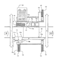
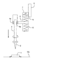
図1は、本発明が適用された実施形態の電子部品実装装置の模式的な平面図、図2は、本実施形態の主要部の部品重量測定機構部の側面図、図3は、制御関係のハードウェア構成を示すブロック図である。 FIG. 1 is a schematic plan view of an electronic component mounting apparatus according to an embodiment to which the present invention is applied, FIG. 2 is a side view of a component weight measuring mechanism unit of a main part of the present embodiment, and FIG. It is a block diagram which shows the hardware constitutions.
電子部品1を実装する基板10は、矢印INに示すように左方から搬入され、部品実装完了後、矢印OUTに示されるように右方から搬出される。基板10には、実装時の基板位置を検出するためのマーク10aが印刷されている。
The
実装時の基板位置に対して、図中下側の位置には、比較的小さく軽量な電子部品1を供給するためのテープフィーダ12が配列されている。該テープフィーダ12は、リールに巻かれたテープ12a(図2)を逐次繰り出しながら、長手方向に等間隔で多数埋め込まれている電子部品1を1つずつ順に供給する。
A
又、実装時の基板位置に対して、図中上側で左端には、比較的大きく重い電子部品1を供給するためのトレイホルダ13が配置されている。なお、該トレイホルダ13の右には、テープフィーダ12が配列されている。
In addition, a
なお、部品廃棄ボックス14及び回収ベルト19は、一旦吸着ノズル2に吸着した電子部品1を、基板10には搭載せず、廃棄あるいは回収するためのものである。通常、高価な電子部品1は回収ベルト19により回収し、その他のものは部品廃棄ボックス14に廃棄する。
The component disposal box 14 and the
装着ヘッド部11は、4つの吸着ノズル2を装着するヘッド部分11aと、1つの吸着ノズル2を装着するヘッド部分11bとを備える。ヘッド部分11aに比べてヘッド部分11bの方が、吸着保持力が大きい吸着ノズル2を装着し易い。装着ヘッド部11に取り付けられた吸着ノズル2は、バキューム機構25(図3)により電子部品1を吸着する。本実施形態において、該バキューム機構25には、供給される圧縮空気を用いて負圧を発生させるエジェクタ、該負圧により電子部品1を吸着する吸着ノズル2、種々の切換え弁その他が含まれる。これら切換え弁は、コントローラ32(図3)によって制御される。
The
なお、図1において、17は、装着ヘッド部原点基準である。この装着ヘッド部原点基準17における原点マーク17a及び17bを、装着ヘッド部11に取り付けられた後述するCCDカメラ15a、15bで撮像し、装着ヘッド部11のX軸原点及びY軸原点を正確に設定するようにしている。
In FIG. 1,
次に、図2において、装着ヘッド部11において、吸着ノズル2は、テープフィーダ12のテープ12aに貼り付けられ、あるいはトレイホルダ13に格納された電子部品1を吸着するものである。
Next, in FIG. 2, in the
この吸着ノズル2は、ノズルシャフト3の下端(先端)に、軸方向の一定値以上の荷重によって嵌合され、又は取り外されるようになっている。ノズルチェンジャ16に納められる該当の吸着ノズル2の位置において、該当の吸着ノズル2が嵌合され、あるいは、取り外され、交換可能になっている。
The
又、ノズルシャフト3は、ノズルブラケット4に対してベアリング4aを介在させて取り付けられ、その軸線回りのθ軸方向に回動できるようにされている。これに対して、ノズルベース8は、装着ヘッド部11において、鉛直のZ軸方向に移動可能になっている。
The
ノズルベース8に対して、ノズルブラケット4は上下動自在になっており、これにより、吸着ノズル2、ノズルシャフト3、ベアリング4a及びノズルブラケット4からなる吸着機構部はノズルベース8に対して上下動自在に保持されている。
The nozzle bracket 4 is movable up and down with respect to the
ノズルベース8において上下動自在のノズルブラケット4の下端を支えるように自重負担ばね5が配置され、その弾性力によりノズルブラケット4を含む吸着機構部の重さを相殺するようになっている。又、ノズルブラケット4の上端に与圧ばね6が配置され、ノズルブラケット4を含む吸着機構部の上下動の移動量に応じ、与圧ばね6は、その弾性力によって与圧ばね6の他端(上端)に配置されたロードセル7に対して与圧を与える。ロードセル7は、吸着機構部の上下動によって与圧ばね6から与えられる与圧の大きさを検出し、該与圧の大きさに応じた信号をコントローラ32に出力する。
A self-weight bearing
これら吸着機構部、自重負担ばね5、与圧ばね6、ロードセル7及びノズルベース8により、本発明が適用される部品重量測定機構部が構成されている。
The adsorbing mechanism, the self-weight bearing
次に、装着ヘッド部11は、図3に示すX軸モータ21が装着された図示されないX軸機構部により矢印Xで示されるX軸方向の軸移動がなされ、Y軸モータ22a及び22bがそれぞれ装着された図示されないY軸左側機構部及びY軸右側機構部により矢印YL及び矢印YRで示されるY軸方向の軸移動がなされる。又、該装着ヘッド部11に内蔵される、Z軸モータ23が装着された図示されないZ軸機構部によりZ軸方向の、θ軸モータ24が装着された図示されないθ軸駆動機構によりθ軸方向の軸移動がなされる。
Next, the
ここで、図1において、ヘッド部分11aには、該ヘッド部分11aにおいて同時吸着可能な4つの電子部品1それぞれの吸着位置を測定するための図示されていないマルチレーザラインセンサが備えられている。またヘッド部分11bには、該ヘッド部分11bに吸着中の電子部品1の吸着位置を測定するための図示されていないレーザラインセンサが備えられている。これらマルチレーザラインセンサ及びレーザラインセンサが出力する信号は、レーザ認識装置34(図3)に入力される。
Here, in FIG. 1, the
レーザ認識装置34は、マルチレーザラインセンサ又はレーザラインセンサが出力する信号に基づいて、該当の吸着ノズル2に吸着されている電子部品1の、θ軸に直交する特定方向の断面長さを測定し、吸着ノズル2における吸着位置を測定する。
The
又、電子部品実装装置においては、図1に示すように、吸着ノズル2に吸着されている電子部品1を下方から撮影するCCD(Charge Coupled Device)カメラ15c、15dが備えられる。ヘッド部分11aの図1中左、又ヘッド部分11bの右には、それぞれ、CCDカメラ15a、15bが設けられている。これらCCDカメラ15a、15bは、基板10の基準マーク10aや、装着ヘッド部原点基準17の原点マーク17a及び17bを上方から撮像し、基板10の搬入位置や、装着ヘッド部11の原点位置を正確に把握し、設定するようになっている。
Further, as shown in FIG. 1, the electronic component mounting apparatus includes CCD (Charge Coupled Device)
図3に示すように、これらCCDカメラ15a〜15dは、CPU(Central Processing Unit)27c及びメモリ27bを有する画像認識装置27が内蔵する、A/D(Analog to Digital)変換器27aに接続されている。該画像認識装置27は、CCDカメラ15a〜15dによって撮影される電子部品1や、基板10上の基準マーク10aの、寸法や中心位置、又、θ軸を中心とする電子部品1の回転角を測定するシステムを構成している。該画像認識装置27は、コントローラ32からの指示を、記憶装置26を介して受ける。
As shown in FIG. 3, these
このコントローラ32は、CPU、RAM(Random Access Memory)、ROM(Read Only Memory)を内蔵し、キーボード28、マウス29、画面表示装置30が接続されている。該画面表示装置30は、画像認識装置27にも接続されている。又、該コントローラ32は、前述したX軸モータ21、Y軸モータ22a及び22b、Z軸モータ23、θ軸モータ24、バキューム機構25、レーザ認識装置34、記憶装置26が接続されている。該コントローラ32は、電子部品実装装置の実装動作の全体的な制御を行う。
The
図4は、本実施形態における生産プログラムの最適化処理を示すフローチャートである。 FIG. 4 is a flowchart showing the optimization process of the production program in this embodiment.
このフローチャートに示される処理は、主としてコントローラ32において行われるものである。
The processing shown in this flowchart is mainly performed in the
まずステップS101では、ステップS112まで続くプログラム編集処理を起動し、電子部品1の外形や大きさだけでなく、部品重量にも応じ、生産プログラムを最適化する処理を開始する。又、ステップS102では、部品重量測定機構部を用いたステップS106まで続く吸着保持力測定処理を実行する。
First, in step S101, a program editing process that continues to step S112 is started, and a process for optimizing the production program is started in accordance with not only the outer shape and size of the
ステップS103では、電子部品実装装置において予め行われている、部品の外形及び大きさに応じた吸着ノズル2選択の設定に基づいて、実装しようとする部品を吸着するための吸着ノズル2を装着する。
In step S103, the
又、ステップS104では、テープフィーダ12又はトレイホルダ13における部品吸着位置においてZ軸を下降させ、実装しようとする電子部品1を吸着する。電子部品1を吸着するため、吸着ノズル2の先端が電子部品1に接触した状態は、図5に示されるようになる。電子部品1に対して吸着ノズル2先端が押し付けられるため、前述の図2の状態に比べ、図5に図示されるように自重負担ばね5が伸長し、与圧ばね6が圧縮され、ロードセル7への与圧は増加する。該与圧の大きさに応じ、又、装着ヘッド部11におけるノズルブラケット4の高さ(位置)は、無負荷時の図2の時より、L1だけ上昇する。
In step S104, the Z-axis is lowered at the component suction position in the
ステップS105でZ軸を上昇すると、ステップS106では、本実施形態の部品重量測定機構部において、実装しようとする電子部品1の重量を測定することができる。電子部品1を吸着した状態でZ軸を上昇させると、図6に示されるような状態になる。この状態では、前述の図2の状態に比べ、吸着している電子部品1の重量により吸着ノズル2が引き下げられる。このため、図示されるように自重負担ばね5が圧縮され、与圧ばね6が伸長し、ロードセル7への与圧は減少する。該与圧の大きさに応じ、装着ヘッド部11におけるノズルブラケット4の高さ(位置)は、無負荷時の図2の時より、L2だけ低くなる。
When the Z axis is raised in step S105, in step S106, the weight of the
図6のように、装着ヘッド部11が上昇し吸着中の電子部品1がテープ12aから離れると、与圧ばね6の与圧減少の度合いに応じたロードセル7から入力される信号に従って、コントローラ32は吸着中の電子部品1の重量を測定することができる。
As shown in FIG. 6, when the mounting
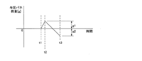
なお、図7は、本実施形態において与圧ばね6がロードセル7に与える与圧を示すタイムチャートである。
FIG. 7 is a time chart showing the pressure applied to the
このタイムチャートにおいて、時刻t1は、図2のように、電子部品1の吸着前の状態である。時刻t2は、図5のように、電子部品1に吸着ノズル2先端が押し付けられた状態であり、図7における荷重g1はこの押し付ける応力に相当する。時刻t3は、図6のように、電子部品1を吸着した状態でZ軸を上昇させた状態であり、図7における荷重g2は吸着中の電子部品1の重量に相当する。
In the time chart, time t1 is a state before the
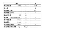
電子部品1の重量が測定されると、ステップS107では、コントローラ32により、その測定値又図8に示す既設定値に従って、次の(1)式から、適切な吸着保持力(F)を求める。更に、(2)式から、吸着可能な最大重量(Max_m)を求めることができる。又、これら吸着保持力(F)及び吸着可能な最大重量(Max_m)が求められると、図9のような既定の設定条件に従って、適切な吸着ノズル2が求められる。
When the weight of the
吸着保持力(F)=完全負荷値(P)×吸着部開口面積(S)/10
……(1)
吸着可能な最大重量(Max_m)
=吸着保持力(F)/9.8/安全率(γ)×1000
……(2)
Adsorption holding force (F) = complete load value (P) × adsorption portion opening area (S) / 10
...... (1)
Maximum weight that can be adsorbed (Max_m)
= Adsorption holding force (F) /9.8/Safety factor (γ) × 1000
(2)
ここで、図9は、本実施形態における吸着保持力(F)及び吸着可能な最大重量(Max_m)の算出結果の一例を示す線図である。 Here, FIG. 9 is a diagram illustrating an example of a calculation result of the adsorption holding force (F) and the maximum adsorbable weight (Max_m) in the present embodiment.
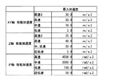
続いて、ステップS108では、コントローラ32により、上述のように求めた吸着保持力(F)、又図10に示される加速度に基づいて、装着ヘッド部11のX軸、Y軸、Z軸、θ軸の各移動軸の移動可能な最大重量を求める。そして、装着ヘッド部11の移動時又搭載動作時における、このような移動軸の適切な速度の設定を行う。
Subsequently, in step S108, the
XY軸の移動可能な最大重量(Max_mXY)
=摩擦係数(μ)×吸着保持力(F)
/(9.8×摩擦係数(μ)+加速度(α))
×1000/安全率(γ) ……(3)
Z軸の移動可能な最大重量(Max_mZ)
=吸着保持力(F) /(9.8×摩擦係数(μ)
+加速度(α))×1000/安全率(γ) ……(4)
θ軸の移動可能な最大重量(Max_mθ)
=3×摩擦係数(μ)×吸着保持力(F)
×開口部直径(D)/(部品辺長(B)^2×加速度(α)
+3 摩擦係数(μ)×9.8× 開口部直径(D))
……(5)
Maximum movable weight of XY axis (Max_mXY)
= Friction coefficient (μ) x Adsorption holding force (F)
/(9.8×friction coefficient (μ) + acceleration (α))
× 1000 / safety factor (γ) …… (3)
Maximum movable weight of Z axis (Max_mZ)
= Adsorption holding force (F) / (9.8 × friction coefficient (μ)
+ Acceleration (α)) × 1000 / Safety factor (γ) (4)
Maximum movable weight of θ axis (Max_mθ)
= 3 x friction coefficient (μ) x adsorption holding force (F)
× Opening Diameter (D) / (Part Side Length (B) ^ 2 × Acceleration (α)
+3 Friction coefficient (μ) x 9.8 x opening diameter (D))
...... (5)
ここで、図11〜図13は、それぞれ、本実施形態におけるXY軸の移動可能な最大重量(Max_mXY)、Z軸の移動可能な最大重量(Max_mZ)、θ軸の移動可能な最大重量(Max_mθ)の算出結果の一例を示す線図である。 Here, FIGS. 11 to 13 are respectively the maximum movable weight (Max_mXY) of the XY axis, the maximum movable weight (Max_mZ) of the Z axis, and the maximum movable weight (Max_mθ of the θ axis) in the present embodiment. It is a diagram which shows an example of the calculation result of).
続いて、ステップS109では、これらステップS107及びステップS108で得られた結果の最適な各データを生産プログラムにおいて反映させる。該データは、吸着保持力、選定される吸着ノズル2、装着ヘッド部11のX軸、Y軸、Z軸、θ軸の各移動軸の速度を示すデータである。
In step S109, the optimum data obtained in steps S107 and S108 is reflected in the production program. The data is data indicating the suction holding force, the
次に、ステップS110では、電子部品1の搭載順番の最適化を行う。即ち、部品の重量に応じて、他のヘッドとペアリングするかどうかの判断を行い、吸着、ヘッド移動、搭載時の電子部品1毎の、装着ヘッド部11のX軸、Y軸、Z軸、θ軸の各移動軸の速度に応じて、電子部品1の搭載順番を決定し、制御し、生産タクトのロスを回避する。
Next, in step S110, the mounting order of the
ステップS111では、これを生産プログラムに反映し、又該生産プログラムを記録保存する。この後、ステップS112では、ステップS101で起動したプログラム編集処理を終了する。 In step S111, this is reflected in the production program, and the production program is recorded and saved. Thereafter, in step S112, the program editing process started in step S101 is terminated.
なお、以上において、摩擦係数は、吸着部の材質が鋼の場合は0.6、ゴムの場合は1として計算している。一般的な摩擦係数は、鋼対鋼で0.4〜0.8程度、ゴム対鋼で1〜4程度である。又、θ軸の移動可能速度は、部品形状が一辺Bmmの正方形で厚みが一様と仮定し、且つ、部品中心を吸着した場合の値となっている。 In the above, the coefficient of friction is calculated as 0.6 when the material of the adsorbing portion is steel and 1 when it is rubber. The general coefficient of friction is about 0.4 to 0.8 for steel to steel and about 1 to 4 for rubber to steel. Further, the movable speed of the θ-axis is a value when the part shape is a square with a side of B mm and the thickness is uniform and the center of the part is adsorbed.
なお、本実施形態の電子部品実装装置は、装着ヘッド部11に備える吸着ノズル2で部品を吸着してから、基板上の該当位置まで吸着ノズル2を移動し、該吸着した電子部品1を実装していく電子部品実装装置であるが、他の形態の電子部品実装装置であってもよい。例えば、吸着ノズル2による電子部品1の吸着は、負圧の空気圧による吸着に限らず、機械動作を行うアクチュエータで電子部品1を挟んで保持するようなものであってもよい。
In the electronic component mounting apparatus of the present embodiment, after the component is sucked by the
又、ロードセルとしては、水晶ロードセル、圧電素子(PZT)ロードセル、ストレンゲージ(ひずみゲージ)ロードセル、半導体ロードセルがあげられる。 Examples of the load cell include a crystal load cell, a piezoelectric element (PZT) load cell, a strain gauge (strain gauge) load cell, and a semiconductor load cell.
1…電子部品
2…吸着ノズル
3…ノズルシャフト
4…ノズルブラケット
5…自重負担ばね
6…与圧ばね
7…ロードセル
8…ノズルベース
10…基板
11…装着ヘッド部
11a、11b…ヘッド部分
12…テープフィーダ
13…トレイホルダ
15a〜15d…CCDカメラ
25…バキューム機構
DESCRIPTION OF
Claims (2)
電子部品を吸着する吸着機構部と、
前記吸着機構部を上下動自在に保持するノズルベースと、
前記吸着機構部の重さを相殺する自重負担ばねと、
与えられた与圧の大きさを検出するロードセルと、
前記ロードセルに、前記吸着機構部の上下動の移動量に応じた与圧を与える与圧ばねと、
を含む部品重量測定機構部を備え、
前記ロードセルで検出された与圧の大きさに基づいて、吸着機構部に吸着した電子部品の重量を測定することを特徴とする電子部品実装装置。 In the electronic component mounting apparatus that moves the suction nozzle to the corresponding position on the substrate after mounting the electronic component with the suction nozzle provided in the mounting head,
An adsorption mechanism that adsorbs electronic components;
A nozzle base for holding the suction mechanism portion so as to be movable up and down;
A self-weight bearing spring that offsets the weight of the suction mechanism,
A load cell that detects the magnitude of the applied pressure;
A pressurizing spring that applies a pressurizing force to the load cell according to the amount of vertical movement of the adsorption mechanism unit;
A component weight measuring mechanism including
An electronic component mounting apparatus that measures the weight of an electronic component adsorbed by an adsorption mechanism unit based on the magnitude of a pressure detected by the load cell.
該適正値に基づいて、部品搭載動作の設定を行なうことを特徴とする電子部品実装装置。 According to the weight of the electronic component measured by the component weight measuring mechanism unit according to claim 1, the suction holding force of the electronic component, the selection of the optimum nozzle, and the X axis and the Y axis of the mounting head unit after the electronic component is sucked , Obtain an appropriate value of at least one of the speeds of the moving axes of the Z axis and the θ axis,
An electronic component mounting apparatus, wherein a component mounting operation is set based on the appropriate value.
Priority Applications (2)
| Application Number | Priority Date | Filing Date | Title |
|---|---|---|---|
| JP2008191426A JP5095542B2 (en) | 2008-07-24 | 2008-07-24 | Electronic component mounting equipment |
| CN200910161513.XA CN101636072B (en) | 2008-07-24 | 2009-07-24 | Mounting device of electronic components |
Applications Claiming Priority (1)
| Application Number | Priority Date | Filing Date | Title |
|---|---|---|---|
| JP2008191426A JP5095542B2 (en) | 2008-07-24 | 2008-07-24 | Electronic component mounting equipment |
Publications (2)
| Publication Number | Publication Date |
|---|---|
| JP2010034095A true JP2010034095A (en) | 2010-02-12 |
| JP5095542B2 JP5095542B2 (en) | 2012-12-12 |
Family
ID=41595053
Family Applications (1)
| Application Number | Title | Priority Date | Filing Date |
|---|---|---|---|
| JP2008191426A Active JP5095542B2 (en) | 2008-07-24 | 2008-07-24 | Electronic component mounting equipment |
Country Status (2)
| Country | Link |
|---|---|
| JP (1) | JP5095542B2 (en) |
| CN (1) | CN101636072B (en) |
Cited By (7)
| Publication number | Priority date | Publication date | Assignee | Title |
|---|---|---|---|---|
| JP2012156200A (en) * | 2011-01-24 | 2012-08-16 | Hitachi High-Tech Instruments Co Ltd | Arithmetic unit calculating setting of component mounting device, component mounting device and program |
| KR101267142B1 (en) | 2010-04-28 | 2013-05-27 | 가부시끼가이샤 히다찌 하이테크 인스트루먼츠 | Electronic components mounting method, electronic components mounting device, and nozzle data creating method |
| JP2017098506A (en) * | 2015-11-27 | 2017-06-01 | ヤマハ発動機株式会社 | Component mounting device and component weight acquisition method |
| JP2017524545A (en) * | 2014-06-05 | 2017-08-31 | メドロボティクス コーポレイション | Articulating robot probe, method and system for incorporating the probe, and method for performing a surgical procedure |
| JP2019117067A (en) * | 2017-12-26 | 2019-07-18 | ミネベアミツミ株式会社 | Load sensor and multiaxial actuator integral with load sensor |
| JP2020020678A (en) * | 2018-08-01 | 2020-02-06 | Thk株式会社 | Actuator load detector |
| JP2021077700A (en) * | 2019-11-06 | 2021-05-20 | パナソニックIpマネジメント株式会社 | Speed condition estimation system, speed condition estimate method, and program |
Families Citing this family (5)
| Publication number | Priority date | Publication date | Assignee | Title |
|---|---|---|---|---|
| JP2012174822A (en) * | 2011-02-21 | 2012-09-10 | Juki Corp | Compression control head of mounter device |
| JP6207758B2 (en) * | 2014-09-26 | 2017-10-04 | ヤマハ発動機株式会社 | Component mounting apparatus, surface mounter, and suction height position detection method |
| CN109247008A (en) * | 2018-10-30 | 2019-01-18 | 重庆隆成电子设备有限公司 | A kind of soft or hard make-up machine and pasting method |
| CN114248426A (en) * | 2022-01-04 | 2022-03-29 | 深圳市领志光机电自动化系统有限公司 | Film pasting device capable of measuring pasting force without segment difference |
| CN114918963A (en) * | 2022-05-31 | 2022-08-19 | 三一汽车制造有限公司 | Sucker mechanism and truss manipulator |
Citations (3)
| Publication number | Priority date | Publication date | Assignee | Title |
|---|---|---|---|---|
| JP2002018758A (en) * | 2000-07-07 | 2002-01-22 | Murata Mfg Co Ltd | Device for sucking parts |
| JP2006147702A (en) * | 2004-11-17 | 2006-06-08 | Juki Corp | Electronic component crimping device |
| JP2006339531A (en) * | 2005-06-03 | 2006-12-14 | Matsushita Electric Ind Co Ltd | Method for determining suction nozzle |
Family Cites Families (5)
| Publication number | Priority date | Publication date | Assignee | Title |
|---|---|---|---|---|
| DE60031865T2 (en) * | 1999-09-02 | 2007-05-24 | Matsushita Electric Industrial Co., Ltd., Kadoma | METHOD AND DEVICE FOR DETECTING A WORKPIECE AND METHOD AND DEVICE FOR FITTING |
| CN1849861B (en) * | 2003-09-10 | 2010-06-16 | 富士机械制造株式会社 | Electronic circuit component mounter |
| CN1914969A (en) * | 2004-01-26 | 2007-02-14 | 株式会社帕普曼 | Device for automatically mounting electronic part and part stock management device |
| JP2005252118A (en) * | 2004-03-08 | 2005-09-15 | Juki Corp | Electronic component packaging apparatus |
| JP2006108384A (en) * | 2004-10-05 | 2006-04-20 | Juki Corp | Mounting device, its mounting load correcting method and nozzle inspecting method |
-
2008
- 2008-07-24 JP JP2008191426A patent/JP5095542B2/en active Active
-
2009
- 2009-07-24 CN CN200910161513.XA patent/CN101636072B/en active Active
Patent Citations (3)
| Publication number | Priority date | Publication date | Assignee | Title |
|---|---|---|---|---|
| JP2002018758A (en) * | 2000-07-07 | 2002-01-22 | Murata Mfg Co Ltd | Device for sucking parts |
| JP2006147702A (en) * | 2004-11-17 | 2006-06-08 | Juki Corp | Electronic component crimping device |
| JP2006339531A (en) * | 2005-06-03 | 2006-12-14 | Matsushita Electric Ind Co Ltd | Method for determining suction nozzle |
Cited By (10)
| Publication number | Priority date | Publication date | Assignee | Title |
|---|---|---|---|---|
| KR101267142B1 (en) | 2010-04-28 | 2013-05-27 | 가부시끼가이샤 히다찌 하이테크 인스트루먼츠 | Electronic components mounting method, electronic components mounting device, and nozzle data creating method |
| JP2012156200A (en) * | 2011-01-24 | 2012-08-16 | Hitachi High-Tech Instruments Co Ltd | Arithmetic unit calculating setting of component mounting device, component mounting device and program |
| JP2017524545A (en) * | 2014-06-05 | 2017-08-31 | メドロボティクス コーポレイション | Articulating robot probe, method and system for incorporating the probe, and method for performing a surgical procedure |
| JP2017098506A (en) * | 2015-11-27 | 2017-06-01 | ヤマハ発動機株式会社 | Component mounting device and component weight acquisition method |
| JP2019117067A (en) * | 2017-12-26 | 2019-07-18 | ミネベアミツミ株式会社 | Load sensor and multiaxial actuator integral with load sensor |
| US11060928B2 (en) | 2017-12-26 | 2021-07-13 | Minebea Mitsumi Inc. | Load sensor and load sensor integrated type multiaxial actuator |
| JP2020020678A (en) * | 2018-08-01 | 2020-02-06 | Thk株式会社 | Actuator load detector |
| WO2020027273A1 (en) * | 2018-08-01 | 2020-02-06 | Thk株式会社 | Load detector for actuator |
| JP2021077700A (en) * | 2019-11-06 | 2021-05-20 | パナソニックIpマネジメント株式会社 | Speed condition estimation system, speed condition estimate method, and program |
| JP7382576B2 (en) | 2019-11-06 | 2023-11-17 | パナソニックIpマネジメント株式会社 | Speed condition estimation device, speed condition estimation method, and program |
Also Published As
| Publication number | Publication date |
|---|---|
| CN101636072A (en) | 2010-01-27 |
| JP5095542B2 (en) | 2012-12-12 |
| CN101636072B (en) | 2014-02-26 |
Similar Documents
| Publication | Publication Date | Title |
|---|---|---|
| JP5095542B2 (en) | Electronic component mounting equipment | |
| JP6807755B2 (en) | Mounting device and control method of mounting device | |
| JP4865492B2 (en) | Mounting parts inspection method | |
| JP6021550B2 (en) | Electronic component mounting equipment | |
| JP6166069B2 (en) | Die bonder and collet position adjustment method | |
| JP4865496B2 (en) | Imaging apparatus and imaging method | |
| JP5174583B2 (en) | Control method of electronic component mounting apparatus | |
| KR20120095323A (en) | Pressurization control head of mounting apparatus | |
| JP2010206103A (en) | Apparatus for manufacturing semiconductor device, and method for manufacturing the semiconductor device | |
| JP4943297B2 (en) | Method and apparatus for controlling pressure mounting head | |
| JP2006114534A (en) | Component carrying device, surface mounting machine, and component testing device | |
| JP5984193B2 (en) | Expanding ring inner diameter measuring system and push-up motion interference avoidance system of die feeding device | |
| JP6207758B2 (en) | Component mounting apparatus, surface mounter, and suction height position detection method | |
| JP4823801B2 (en) | Electronic component mounting method and apparatus | |
| KR101266714B1 (en) | Componemt mounting method of component placement apparatus and component placement apparatus | |
| EP3518646B1 (en) | Component mounter | |
| JP5686321B2 (en) | Mounting device, electronic component mounting method, and substrate manufacturing method | |
| WO2018173137A1 (en) | Component mounting machine and nozzle height control method | |
| US8662009B2 (en) | Adhesive application apparatus | |
| JP7307546B2 (en) | Board working device | |
| JP6780899B2 (en) | Control method of mounting processing unit, mounting device and mounting processing unit | |
| JP2009212138A (en) | Component mounting device | |
| WO2024089852A1 (en) | Control device, robot system, and control method | |
| CN113727817B (en) | Controller for controlling a power supply | |
| JP2004071891A (en) | Part mounting device |
Legal Events
| Date | Code | Title | Description |
|---|---|---|---|
| A621 | Written request for application examination |
Free format text: JAPANESE INTERMEDIATE CODE: A621 Effective date: 20110720 |
|
| A977 | Report on retrieval |
Free format text: JAPANESE INTERMEDIATE CODE: A971007 Effective date: 20120820 |
|
| TRDD | Decision of grant or rejection written | ||
| A01 | Written decision to grant a patent or to grant a registration (utility model) |
Free format text: JAPANESE INTERMEDIATE CODE: A01 Effective date: 20120828 |
|
| A01 | Written decision to grant a patent or to grant a registration (utility model) |
Free format text: JAPANESE INTERMEDIATE CODE: A01 |
|
| A61 | First payment of annual fees (during grant procedure) |
Free format text: JAPANESE INTERMEDIATE CODE: A61 Effective date: 20120919 |
|
| R150 | Certificate of patent or registration of utility model |
Ref document number: 5095542 Country of ref document: JP Free format text: JAPANESE INTERMEDIATE CODE: R150 Free format text: JAPANESE INTERMEDIATE CODE: R150 |
|
| FPAY | Renewal fee payment (event date is renewal date of database) |
Free format text: PAYMENT UNTIL: 20150928 Year of fee payment: 3 |