JP2010032426A - Optical coherence tomographic imaging method and optical coherence tomographic imaging apparatus - Google Patents
Optical coherence tomographic imaging method and optical coherence tomographic imaging apparatus Download PDFInfo
- Publication number
- JP2010032426A JP2010032426A JP2008196619A JP2008196619A JP2010032426A JP 2010032426 A JP2010032426 A JP 2010032426A JP 2008196619 A JP2008196619 A JP 2008196619A JP 2008196619 A JP2008196619 A JP 2008196619A JP 2010032426 A JP2010032426 A JP 2010032426A
- Authority
- JP
- Japan
- Prior art keywords
- spectrum
- wavelength spectrum
- light
- elements
- wavelength
- Prior art date
- Legal status (The legal status is an assumption and is not a legal conclusion. Google has not performed a legal analysis and makes no representation as to the accuracy of the status listed.)
- Granted
Links
Images


Classifications
-
- G—PHYSICS
- G01—MEASURING; TESTING
- G01B—MEASURING LENGTH, THICKNESS OR SIMILAR LINEAR DIMENSIONS; MEASURING ANGLES; MEASURING AREAS; MEASURING IRREGULARITIES OF SURFACES OR CONTOURS
- G01B9/00—Measuring instruments characterised by the use of optical techniques
- G01B9/02—Interferometers
- G01B9/0209—Low-coherence interferometers
- G01B9/02091—Tomographic interferometers, e.g. based on optical coherence
-
- G—PHYSICS
- G01—MEASURING; TESTING
- G01B—MEASURING LENGTH, THICKNESS OR SIMILAR LINEAR DIMENSIONS; MEASURING ANGLES; MEASURING AREAS; MEASURING IRREGULARITIES OF SURFACES OR CONTOURS
- G01B9/00—Measuring instruments characterised by the use of optical techniques
- G01B9/02—Interferometers
- G01B9/02041—Interferometers characterised by particular imaging or detection techniques
- G01B9/02044—Imaging in the frequency domain, e.g. by using a spectrometer
-
- G—PHYSICS
- G01—MEASURING; TESTING
- G01B—MEASURING LENGTH, THICKNESS OR SIMILAR LINEAR DIMENSIONS; MEASURING ANGLES; MEASURING AREAS; MEASURING IRREGULARITIES OF SURFACES OR CONTOURS
- G01B9/00—Measuring instruments characterised by the use of optical techniques
- G01B9/02—Interferometers
- G01B9/02083—Interferometers characterised by particular signal processing and presentation
-
- G—PHYSICS
- G01—MEASURING; TESTING
- G01N—INVESTIGATING OR ANALYSING MATERIALS BY DETERMINING THEIR CHEMICAL OR PHYSICAL PROPERTIES
- G01N21/00—Investigating or analysing materials by the use of optical means, i.e. using sub-millimetre waves, infrared, visible or ultraviolet light
- G01N21/17—Systems in which incident light is modified in accordance with the properties of the material investigated
- G01N21/47—Scattering, i.e. diffuse reflection
- G01N21/4795—Scattering, i.e. diffuse reflection spatially resolved investigating of object in scattering medium
Landscapes
- Physics & Mathematics (AREA)
- General Physics & Mathematics (AREA)
- General Health & Medical Sciences (AREA)
- Health & Medical Sciences (AREA)
- Chemical & Material Sciences (AREA)
- Radiology & Medical Imaging (AREA)
- Optics & Photonics (AREA)
- Life Sciences & Earth Sciences (AREA)
- Nuclear Medicine, Radiotherapy & Molecular Imaging (AREA)
- Analytical Chemistry (AREA)
- Biochemistry (AREA)
- Immunology (AREA)
- Pathology (AREA)
- Engineering & Computer Science (AREA)
- Signal Processing (AREA)
- Investigating Or Analysing Materials By Optical Means (AREA)
Abstract
Description
本発明は、光干渉断層撮像装置に関し、特に医療分野に用いられる干渉光学系を有する光干渉断層撮像装置に関するものである。 The present invention relates to an optical coherence tomography apparatus, and more particularly to an optical coherence tomography apparatus having an interference optical system used in the medical field.
現在、光学機器を用いた眼科用機器には様々なものが使用されている。例えば、前眼部撮影機、眼底カメラ、共焦点レーザー走査検眼鏡(Scanning Laser Ophthalmoscope: SLO)等である。中でも、光干渉断層撮像装置(Optical Coherence Tomography:OCT、以下OCT装置と記す)は、被検査物の断層像を高解像度に得る装置であり、網膜の専門外来では必要不可欠な装置になりつつある。 Currently, various ophthalmic devices using optical devices are used. For example, an anterior ocular segment photographing machine, a fundus camera, a confocal laser scanning ophthalmoscope (SLO), or the like. Among them, an optical coherence tomography (OCT) (hereinafter referred to as an OCT apparatus) is a device that obtains a tomographic image of an inspection object with high resolution, and is becoming an indispensable device for specialized retina outpatients. .
上記OCT装置は、光源として低コヒーレント光を用いる。光源からの光はビームスプリッタなどの分割光路を介して測定光と参照光に分ける。一方の測定光は、測定光路を介して眼などの被検査物に照射し、その戻り光を検出光路を介して検出位置に導く。戻り光とは、被検査物に対する光の照射方向における界面に関する情報等が含まれる反射光や散乱光のことである。他方の参照光は参照光路を介して参照ミラーなどで反射させ、検出位置に導く。この戻り光と参照光を干渉させ、解析することによって被検査物の層構造の情報を得ることができる。さらに、低コヒーレント光を2次元にスキャンすることで3次元の断層像を得ることができる。 The OCT apparatus uses low coherent light as a light source. The light from the light source is divided into measurement light and reference light through a split optical path such as a beam splitter. One measurement light irradiates an inspection object such as an eye via the measurement optical path, and guides the return light to the detection position via the detection optical path. The return light is reflected light or scattered light including information on the interface in the light irradiation direction with respect to the inspection object. The other reference light is reflected by a reference mirror or the like through the reference light path and guided to the detection position. Information on the layer structure of the object to be inspected can be obtained by interfering and analyzing the return light and the reference light. Furthermore, a three-dimensional tomographic image can be obtained by scanning low-coherent light in two dimensions.
特許文献1には医療分野に用いられるOCT装置が開示されている。ここでは、被検査物の一点の測定に対し参照ミラーを不連続に3回位置変化させて分光スペクトルを得る。スキャナなどによって一次元スキャンすることで所望のエリアで必要な分光スペクトルを得ることができる。最後に、これらのデータを解析することによって2次元の断層像を得ている。
特許文献1では所望のエリアにおける一点の測定に対して、複数回参照ミラーの位置を変化させている。この方式は、測定に時間がかかるだけでなく、参照ミラーの精密な位置制御も求められる。
In
一方、医療分野で用いられるOCT装置においては、参照ミラーを固定して、分光器からの波長スペクトルを波数スペクトルに変換し、フーリエ変換により断層を計測する方法がある。この方式はフーリエドメインOCT装置(FD−OCT)などと呼ばれ、広帯域の光源を用いる方式と光源の波長を掃引する方式などがある。通常、FD−OCTにおいて波長スペクトルを波数スペクトルに変換する際、波数が波長の逆数であるため、波数スペクトルが等間隔にならない。当然このままフーリエ変換を行うと正確な断層情報を得られない場合がある。そのため、波長スペクトルを物理現象に忠実な等間隔の波数スペクトルに変換し、より正確な断層情報を得ることができる信号処理方法が求められていた。 On the other hand, in an OCT apparatus used in the medical field, there is a method in which a reference mirror is fixed, a wavelength spectrum from a spectroscope is converted into a wave number spectrum, and a tomography is measured by Fourier transform. This method is called a Fourier domain OCT apparatus (FD-OCT) or the like, and there are a method using a broadband light source and a method of sweeping the wavelength of the light source. Normally, when a wavelength spectrum is converted to a wave number spectrum in FD-OCT, the wave number spectrum is not equal because the wave number is the reciprocal of the wavelength. Of course, if the Fourier transform is performed as it is, accurate tomographic information may not be obtained. Therefore, there has been a demand for a signal processing method capable of converting the wavelength spectrum into a wave number spectrum with equal intervals faithful to a physical phenomenon and obtaining more accurate tomographic information.
本発明は上記課題を鑑みてなされたものであり、その目的は、より正確な断層情報を得ることにある。 The present invention has been made in view of the above problems, and an object thereof is to obtain more accurate tomographic information.
本発明に係る光干渉断層撮像方法は、
光源からの光を分割光路を介して測定光と参照光とに分割し、
前記測定光を測定光路を介して被検査物に照射し、かつ、前記被検査物からの戻り光を検出光路を介して検出位置に導き、
前記参照光を参照光路を介して前記検出位置に導いて、
前記検出位置に導かれた前記戻り光と前記参照光とが干渉した干渉光の波長スペクトルを取得し、該波長スペクトルを解析する波長スペクトル解析手段によって前記被検査物の断層画像を撮像する光干渉断層撮像装置における光干渉断層撮像方法であって、
波長スペクトルを取得する波長スペクトル取得工程と、
前記波長スペクトルを波数スペクトルに変換し、要素数を減らして、等間隔の波数スペクトルにする波数スペクトル取得工程と、
前記波数スペクトルから被検査物の断層の情報を取得する断層情報取得工程と、
を含むことを特徴とする。
An optical coherence tomographic imaging method according to the present invention includes:
The light from the light source is divided into measurement light and reference light through the split light path,
Irradiating the object to be inspected with the measurement light through the measurement optical path, and guiding the return light from the object to be detected to the detection position through the detection optical path;
Guiding the reference light to the detection position via a reference light path;
Optical interference that obtains a wavelength spectrum of interference light in which the return light guided to the detection position interferes with the reference light, and captures a tomographic image of the inspection object by wavelength spectrum analysis means for analyzing the wavelength spectrum An optical coherence tomographic imaging method in a tomographic imaging apparatus,
A wavelength spectrum acquisition step of acquiring a wavelength spectrum;
Converting the wavelength spectrum into a wave number spectrum, reducing the number of elements to obtain a wave number spectrum of equal intervals; and
A tomographic information acquisition step of acquiring information on a fault of the object to be inspected from the wave number spectrum;
It is characterized by including.
また、本発明に係る光干渉断層撮像装置は、
光源と、
光源からの光を測定光と参照光とに分割し、前記測定光を被検査物に導くとともに、前記被検査物からの戻り光を検出位置に導き、かつ、前記参照光を前記検出位置に導く光学系と、
前記検出位置に配置され、前記戻り光と前記参照光とが干渉した干渉光から波長スペクトルを取得する波長スペクトル取得手段と、
取得された波長スペクトルから前記被検査物の断層画像を撮像する波長スペクトル解析手段とを有し、
前記波長スペクトル解析手段は、
前記波長スペクトルを波数スペクトルに変換し、要素数を減らして、等間隔の波数スペクトルにする波数スペクトル取得工程と、
前記波数スペクトルから被検査物の断層の情報を取得する断層情報取得工程と、
を実行することを特徴とする。
In addition, the optical coherence tomography apparatus according to the present invention,
A light source;
The light from the light source is divided into measurement light and reference light, the measurement light is guided to the inspection object, return light from the inspection object is guided to the detection position, and the reference light is set to the detection position. A guiding optical system;
A wavelength spectrum acquisition unit that is arranged at the detection position and acquires a wavelength spectrum from interference light in which the return light and the reference light interfere with each other;
Wavelength spectrum analyzing means for capturing a tomographic image of the inspection object from the acquired wavelength spectrum,
The wavelength spectrum analyzing means includes
Converting the wavelength spectrum into a wave number spectrum, reducing the number of elements to obtain a wave number spectrum of equal intervals; and
A tomographic information acquisition step of acquiring information on a fault of the object to be inspected from the wave number spectrum;
It is characterized by performing.
本発明によればフーリエドメインの光干渉断層撮像装置において、波長スペクトルから物理現象に忠実な等間隔の波数スペクトルを得ることができ、より正確な断層情報を得ることができる。 According to the present invention, in a Fourier-domain optical coherence tomographic imaging apparatus, it is possible to obtain a wavenumber spectrum at equal intervals faithful to a physical phenomenon from a wavelength spectrum, and to obtain more accurate tomographic information.
本発明の実施形態において、光干渉断層撮像装置は、光源からの光を分割光路を介して測定光と参照光とに分割する手段を有する。また、測定光を測定光路を介して被検査物に照射し、かつ測定光の前記被検査物からの戻り光を検出光路を介して検出位置に導くことができる。さらに、参照光を参照光路を介して検出位置に導いて、検出位置に導かれた戻り光と参照光とが干渉した干渉光の波長スペクトルを得ることができる。そして、波長スペクトル解析手段をもって断層画像を撮像することができる。さらに、波長スペクトル解析手段は、波長スペクトルを取得する第1の工程を有する。次に、波長スペクトルの要素数を増やす第2の工程を有する。さらに、波長スペクトルを波数スペクトルに変換し、要素数を減らして、等間隔の波数スペクトルにする第3の工程を有する。そして、波数スペクトルから被検査物の断層の情報を取得する第4の工程を有することができる。なお、第1の工程における波長スペクトルの要素数が十分に多い場合には、第2の工程は省略しても良い。 In the embodiment of the present invention, the optical coherence tomography apparatus includes means for dividing light from a light source into measurement light and reference light via a divided light path. Further, it is possible to irradiate the inspection object through the measurement optical path and guide the return light of the measurement light from the inspection object to the detection position through the detection optical path. Furthermore, it is possible to guide the reference light to the detection position via the reference light path, and obtain the wavelength spectrum of the interference light in which the return light guided to the detection position interferes with the reference light. A tomographic image can be taken with the wavelength spectrum analyzing means. Furthermore, the wavelength spectrum analyzing means has a first step of acquiring a wavelength spectrum. Next, there is a second step of increasing the number of elements of the wavelength spectrum. Furthermore, it has the 3rd process which converts a wavelength spectrum into a wave number spectrum, reduces the number of elements, and makes it an equal interval wave number spectrum. And it can have the 4th process of acquiring the information on the tomographic object's tomography from a wave number spectrum. If the number of wavelength spectrum elements in the first step is sufficiently large, the second step may be omitted.
次に、本発明の実施例について説明する。 Next, examples of the present invention will be described.
[第1の実施形態]
第1の実施形態においては、本発明を適用した光干渉断層撮像装置について図面を用いて説明する。
[First Embodiment]
In the first embodiment, an optical coherence tomography apparatus to which the present invention is applied will be described with reference to the drawings.
<光学系の構成>
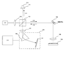
最初に、図1を参照して、OCT装置の構成を大まかに説明する。光源101から出射した光はレンズ102を介し、ビームスプリッタ103によって測定光112と参照光114とに分割される。測定光112は、XYスキャナ104、対物レンズ105を介して被検査物106に到達する。被検査物には透過性の膜が設けられており、それらの表面および界面で散乱および反射された戻り光113は、対物レンズ105、XYスキャナ104、ビームスプリッタ103の順で戻る。さらに、結像レンズ107を介して、検出位置に配置された分光器108に到達する。一方、参照光114は参照ミラー115によって反射される。なお、参照ミラー115は位置調整機構116によって光路長を調整することができる。また、参照光114はビームスプリッタ103によって、戻り光113と合波される。
<Configuration of optical system>
First, the configuration of the OCT apparatus will be roughly described with reference to FIG. Light emitted from the
光源101は代表的な低コヒーレント光源であるSLD(Super Luminescent Diode)である。その波長は例えば830nm、バンド幅50nmである。なお、バンド幅は得られる断層像の光軸方向の分解能に影響するため重要なパラメーターとなる。また、光源の種類は、ここではSLDを選択したが、低コヒーレント光が出射できればよく、ASE(Amplified Spontaneous Emission)等も用いることができる。当然、被検査物の内容によっては、ハロゲンランプなどの他の光源を利用してもよい。ただし、波長は、得られる断層像の横方向の分解能に影響するため、横方向の分解能を重視する場合には短波長であることが望ましい。
The
分光器108は、プリズム109および撮像素子110などで構成されており、測定光を分光する。撮像素子110としては、CCD型ラインセンサーを採用可能である。分光した光は分光器内部の撮像素子によって波長のスペクトルデータとして取得される。
The
撮像素子で撮像された波長のスペクトルデータはコンピューター111で解析される。すなわち、コンピューター111が波長スペクトル解析手段に相当する。当然コンピューターは解析を行うだけでなく、データの記憶、画像の表示、測定の指令を出す機能などを有している。また、コンピューター制御によりXYスキャナで測定光を被検査物に対して光軸に垂直な方向にラスタースキャンし、被検査物の断面像を得ることができる。コンピューター111は、CPUおよびメモリーなどから構成され、CPUがプログラムを実行することで上記の各機能を実現する。ただし、上記の各機能の一部または全部を専用のハードウェアによって実現しても構わない。
The spectrum data of the wavelength imaged by the image sensor is analyzed by the
<信号処理>
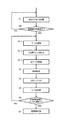
本発明の信号処理工程について図2を用いて説明する。
<Signal processing>
The signal processing process of the present invention will be described with reference to FIG.
まず、S1の工程にて、分光器から波長スペクトルを取得する(波長スペクトル取得工程)。このときのサンプリング数は撮像素子110の画素数のN(例えば2048)個である。スペクトルの情報としては、波長とその波長に対する強度である。まず、波長は分光器108の特性で決まるので一次元配列に予め格納しておく。取得した強度データは別の一次元配列に格納する。ここで、i番目の波長および強度の要素をそれぞれ、sλ(i)、sI(i)とし、便宜的にこの組み合わせを(sλ(i),sI(i))として表示する。その要素iは0番からN−1番までである。図3(a)は波長に対する強度のグラフを模式的に示したものである。サンプリング間隔は波長に対して等間隔で、波長の最小値は805nm、最大値は855nmである。なお、分光器108の特性によっては、波
長に対して等間隔でない場合もある。そのような場合には適宜補間した要素を用いてもよい。
First, in step S1, a wavelength spectrum is acquired from the spectroscope (wavelength spectrum acquisition step). The sampling number at this time is N (for example, 2048) of the number of pixels of the
次に、S2の工程にて、波長スペクトルを補間し、サンプリング点の数(要素数)をM倍(例えば16倍)に増やした波長スペクトルデータを生成する(要素数拡張工程)。補間する方法は直線補間などが挙げられる。補間する前のi番目の要素は補間した後にM・i番目の要素となる。なお、M・iはMとiの乗算である。M・i番目とM・(i+1)番目の要素の間はM・i+jと表すことができる。ただし、iは0からN−1,jは0からM−1で、M・N個の全ての要素を重複することなく記述することができる。直線補間の場合、M・i+j番目の要素は(sλ(i),sI(i))および(sλ(i+1),sI(i+1))を用いると数式1のように表される。
Next, in step S2, wavelength spectrum is interpolated to generate wavelength spectrum data in which the number of sampling points (number of elements) is increased M times (for example, 16 times) (element number expansion step). Examples of the interpolation method include linear interpolation. The i-th element before interpolation becomes the M · i-th element after interpolation. M · i is a multiplication of M and i. The area between the M · i th and M · (i + 1) th elements can be expressed as M · i + j. However, i is 0 to N−1, j is 0 to M−1, and all M · N elements can be described without duplication. In the case of linear interpolation, the M · i + j-th element is expressed as

図3(b)に補間した後の波長に対する強度のグラフを模式的に示す。サンプリング間隔は等間隔で、要素数がM倍になっているため高密度になる。 FIG. 3B schematically shows a graph of intensity with respect to the wavelength after interpolation. Sampling intervals are equal, and the number of elements is M times, resulting in high density.
S3の工程にて、波長スペクトルを波数スペクトルに変換する(波数スペクトル取得工程)。波数は波長の逆数である。従って、i番目の波数および強度の要素を(pw(i)、pI(i))として、数式2のように表される。すなわち、波数に対して昇順に並べ直すと強度の順番が反転する。なお、要素数は0番からM・N−1番までのM・N個である。
In step S3, the wavelength spectrum is converted into a wave number spectrum (wave number spectrum acquisition step). The wave number is the reciprocal of the wavelength. Therefore, the i-th wave number and intensity elements are expressed as
図3(c)に波数に対する強度のグラフを模式的に示す。波長に対して等間隔であるため、波数に変換すると、波数が小さくなるほど高密度になっている。 FIG. 3C schematically shows a graph of intensity with respect to wave number. Since they are equally spaced with respect to the wavelength, when converted into wave numbers, the smaller the wave number, the higher the density.
S4の工程にて、再サンプリングを行う。pw(0)からpw(M・N−1)の間のサンプリング数をP・Nとして、そのときの要素を(uw(k),uI(k))とする。Pは例えば2である。このとき、uw(k)は数式3のようになる。 Re-sampling is performed in step S4. Let P · N be the number of samples between p w (0) and p w (M · N−1), and let the elements at that time be (u w (k), u I (k)). P is, for example, 2. At this time, u w (k) is expressed by Equation 3.
一方uI(k)は以下のように決定する。このアルゴリズムでは、まず、uw(k)に最も近いpw(j)を探し、それに対応するpI(j)をuI(k)に代入する。 On the other hand, u I (k) is determined as follows. In this algorithm, first, p w (j) closest to u w (k) is searched, and p I (j) corresponding thereto is substituted into u I (k).
すなわち、
![]()
![]()
なお、MがPに対して十分大きければこの方法によって十分精度の高いサンプリングが行える。そうでない場合には、uw(k)の値に応じて、pI(j)およびpI(j+1)を使って直線補間をしてuI(k)を計算してもよい。 If M is sufficiently larger than P, sufficiently accurate sampling can be performed by this method. Otherwise, u I (k) may be calculated by linear interpolation using p I (j) and p I (j + 1) according to the value of u w (k).
図3(d)に等間隔にサンプリングした波数に対する強度のグラフを模式的に示す。従来の方法においては、波長スペクトルから要素数を変更しないまま波数スペクトルに変換していた。波長は波数の逆数であるから不等間隔であり、解析に必要な物理現象に忠実な等間隔の波数スペクトルを得ることが難しかった。一方、本発明の方法では、等間隔の波数スペクトルを得ることができるので、正確な解析が行えるようになる。さらに、データ数はN個からN・M個に増やし、波数に変換するときにN・P個に減らしている。ここで、Mを十分大きくすることによって、波数スペクトルをより正確に取得することができる。 FIG. 3D schematically shows a graph of intensity with respect to wave numbers sampled at equal intervals. In the conventional method, the wavelength spectrum is converted into the wave number spectrum without changing the number of elements. Since the wavelength is the reciprocal of the wave number, it is non-uniformly spaced, and it is difficult to obtain a wave number spectrum with equal intervals faithful to the physical phenomenon required for analysis. On the other hand, according to the method of the present invention, a wavenumber spectrum with equal intervals can be obtained, so that an accurate analysis can be performed. Further, the number of data is increased from N to N · M, and reduced to N · P when converting to wave number. Here, by making M sufficiently large, the wave number spectrum can be obtained more accurately.
S5の工程にて、フーリエ変換を行い、被検査物の断層を計測する(断層情報取得工程)。計測した断層のデータはコンピューターのメモリーやハードディスクに順次格納される。 In step S5, Fourier transform is performed to measure a tomographic object tomography (tomographic information acquisition step). The measured tomographic data is sequentially stored in computer memory and hard disk.
S6の工程にて、全ての検査領域でのデータ処理が終了したかどうかを判断する。終了していない場合はS1に戻り、全ての検査領域でデータ処理が終了するまで行う。 In step S6, it is determined whether or not the data processing in all inspection areas has been completed. If not completed, the process returns to S1 until data processing is completed in all inspection areas.
S7の工程にて、S5の工程にて計算した断層のデータから3Dの断層像を形成することができる。 In the step S7, a 3D tomographic image can be formed from the tomographic data calculated in the step S5.
なお本発明の方法では、要素数がS1の工程のN個から、S2の工程でM・N個になり,S4の工程でN・Pになっているが、かならずしもNの倍数にする必要はない。つまり、S2の工程でS1以上の要素数にし、S2の工程よりS3の要素数が少なければよい。また、S1の工程で十分の要素数があれば、S2の工程を飛ばして、S4の工程でS1の工程の要素数より減らしてもよい。当然、S2の工程の要素数をS1の工程の要素数より増やした後、S4の工程の要素数をS1の工程の要素数より減らしてもよい。S4の工程の要素数を減らすことによってS5の工程以降の時間を短縮することができる。さらに、S1,S2,S4の工程の要素数を2のべき乗にすることによって高速フーリエ変換(FFT)を行うことができる。なお、離散値のフーリエ変換はDFTと呼ばれ、FFTはその特殊な場合である。 In the method of the present invention, the number of elements is changed from N in the process of S1 to M · N in the process of S2, and N · P in the process of S4. Absent. That is, it is sufficient that the number of elements is equal to or greater than S1 in the step S2, and the number of elements in S3 is smaller than that in the step S2. Further, if there is a sufficient number of elements in the step S1, the step S2 may be skipped and the number of elements in the step S1 may be reduced in the step S4. Of course, after the number of elements in the step S2 is increased from the number of elements in the step S1, the number of elements in the step S4 may be reduced from the number of elements in the step S1. By reducing the number of elements in the step S4, the time after the step S5 can be shortened. Furthermore, fast Fourier transform (FFT) can be performed by making the number of elements in the steps S1, S2, and S4 to be a power of two. The discrete Fourier transform is called DFT, and FFT is a special case.
上記の信号処理は、汎用のコンピューターに組み込んだプログラムによって実行してもよいが、当然、別のハードウェアとして専用のLSIを用いてもよい。また、FPGA(Field Programmable Gate Alley)などを用いてもよい。 The above signal processing may be executed by a program incorporated in a general-purpose computer, but naturally, a dedicated LSI may be used as another hardware. Alternatively, a field programmable gate array (FPGA) may be used.
[第2の実施形態]
第2の実施形態においては、本発明を適用した眼科用のOCT装置の光学系について図4を用いて詳しく説明する。
[Second Embodiment]
In the second embodiment, an optical system of an ophthalmic OCT apparatus to which the present invention is applied will be described in detail with reference to FIG.
<光学系の構成>
図4は、全体としてマッハツェンダー干渉系を構成している。光源401から出射された光はシングルモードファイバー410−1を通して、レンズ411−1に導かれる。さらに、ビームスプリッタ403−1によって参照光405と測定光406とに分割される。測定光406は、被検査物である眼407によって反射や散乱により戻り光408となって戻された後、ビームスプリッタ403−2によって、参照光405と合波され、分光器421に入射する。なお、光源401は代表的な低コヒーレント光源であるSLD(Super Luminescent Diode)である。波長は眼を測定することを鑑みると、近赤外光が適する。
<Configuration of optical system>
FIG. 4 constitutes a Mach-Zehnder interference system as a whole. The light emitted from the
参照光405の光路について説明する。ビームスプリッタ403−1によって分割された参照光405はミラー414−1〜3に連続して入射され、方向を変えることで、ビームスプリッタ403−2により分光器421に入射される。ここで、415−1〜2は分散補償用ガラスである。分散補償用ガラス415−1の長さはL1であり、一般的な眼の奥行きの2倍と等しいことが望ましい。分散補償用ガラス415−1は眼407に測定光406が往復したときの分散を、参照光405に対して補償するものである。ここでは、日本人の平均的な眼球の直径とされる23mmの2倍のL1=46mmとする。さらに、417は電動ステージであり、矢印で図示している方向に移動することができ、参照光405の光路長を、調整・制御することができる。分散補償用ガラス415−2は眼407のスキャンに用いられるレンズ420−1,2の分散補償を目的としたものである。
The optical path of the
測定光406の光路について説明する。ビームスプリッタ403−1によって分割された測定光406は、ビームスプリッタ403−3で反射される。次に、XYスキャナ419のミラーに入射される。XYスキャナ419は、網膜423上を光軸に垂直な方向にラスタースキャンするものである。また、測定光406の中心はXYスキャナ419のミラーの回転中心と一致するように調整されている。レンズ420−1,2は網膜423を走査するための光学系であり、測定光406を角膜422の付近を支点として、網膜423をスキャンする役割がある。ここでは、レンズ420−1,2の焦点距離はそれぞれ50mm、50mmである。測定光406は眼407に入射すると、網膜423からの反射や散乱により戻り光408となる。さらに、戻り光408はビームスプリッタ403−3によって戻り光408−1と408−2とに分割され、その一方である戻り光408−1は、分光器421に導かれる。ここで、分光器421は、回折格子型分光器である。その中の撮像素子はCCD型ラインセンサーである。分光器421で取得された波長スペクトルなどのデータはコンピューター425に取り入れられる。
The optical path of the
また、もう一方の戻り光408−2はビームスプリッタ403−1を透過され、検出器424に導かれる。検出器424は、干渉信号と同様に、電気的にコンピューター425に取り入れられ、戻り光408−2の強度を記録および表示とを行うことができる。また、検出器424で得られる信号は、網膜423での反射や散乱による戻り光408−2の強度信号であり、深さ分解能を持たない。検出器424は、例えば高速・高感度な光センサであるAPD(Avalanche Photo Diode)が用いられる。
The other return light 408-2 is transmitted through the beam splitter 403-1 and guided to the
<信号処理>
信号処理方法においては、第1の実施形態との差異について、図5,6を参照して説明する。この方式では、先にデータを取得する点、範囲を拡張する方法が第1の実施形態と
の主な違いとなる。なお、図5は本実施形態における信号処理の流れを示すフローチャートであり、図6は信号処理における信号の様子を説明する図である。
<Signal processing>
In the signal processing method, differences from the first embodiment will be described with reference to FIGS. In this system, the main difference from the first embodiment is that the data is acquired first and the method of extending the range. FIG. 5 is a flowchart showing the flow of signal processing in this embodiment, and FIG. 6 is a diagram for explaining the state of signals in signal processing.
S1の工程では第1の実施形態と同様に波長スペクトル(図6(a))を取得する。なお、i番目の波長および強度の要素をそれぞれ、sλ(i)、sI(i)とする。取得したスペクトルのデータはコンピューター425のメモリーやハードディスクに順次格納される。
In the step S1, a wavelength spectrum (FIG. 6A) is acquired in the same manner as in the first embodiment. Note that elements of the i-th wavelength and intensity are s λ (i) and s I (i), respectively. The acquired spectrum data is sequentially stored in the memory or hard disk of the
S8の工程では波長スペクトルの取得が検査領域の各位置で終了したかどうかを判断する。全検査領域で終了した場合はS2−1の工程に進む。信号処理に時間がかかるような場合は、検査領域のデータの取得を信号処理より優先して行うことが重要である。例えば、被検査物が目のように動くようなものである場合である。 In step S8, it is determined whether acquisition of the wavelength spectrum has been completed at each position in the inspection region. If the process is completed for all inspection areas, the process proceeds to step S2-1. When signal processing takes time, it is important to prioritize acquisition of inspection region data over signal processing. For example, this is a case where the object to be inspected moves like an eye.
S2−1の工程で波長スペクトルデータに対してフーリエ変換を行う。強度の要素SI(i)は数式6のようになる。フーリエ変換後の信号は、図6(b)に示すようになる。一般にi番目の要素とN−i番目の要素の強度は同じであり、N/2を境とするミラー像となる。また、0番目の要素は定数成分である。 In step S2-1, Fourier transform is performed on the wavelength spectrum data. Strength element S I (i) becomes as Equation 6. The signal after the Fourier transform is as shown in FIG. In general, the i-th element and the Ni-th element have the same intensity, resulting in a mirror image with N / 2 as a boundary. The 0th element is a constant component.
なお、分光器421の特性によりスペクトルデータが波長に対して等間隔でない場合は、等間隔に補間したsλ(i)、sI(i)を利用してもよい。この判断基準は例えば等間隔に分割したときと比較して1%以上の誤差があるときである。
If the spectral data is not equally spaced with respect to the wavelength due to the characteristics of the
S2−2の工程で、SI(i)のN/2番目の要素を境に分け、その間にゼロを挿入し、数式7のようにMN個の要素となるように拡張する(Mは2以上の整数)。当然、iは整数である。要素数を拡張したスペクトルデータを図6(c)に示す。なお、N/2が整数の時はN/2の要素は2回使うことになる。従って、i番目の要素のフーリエ変換とMN−i番目の要素が一致する。ただし、N/2付近のデータは、サンプリング定理による復元できる限界なので、0となるようなシステムになっていることが望ましい。 In the step S2-2, the N / 2th element of S I (i) is divided into boundaries, and zeros are inserted between them to expand to MN elements as shown in Equation 7 (M is 2). Or an integer). Of course, i is an integer. FIG. 6C shows spectral data with the number of elements extended. When N / 2 is an integer, the element of N / 2 is used twice. Therefore, the Fourier transform of the i-th element matches the MN-i-th element. However, since data near N / 2 can be restored by the sampling theorem, it is desirable that the system be zero.
S2−3の工程で、このS’I(i)を逆フーリエ変換することによって、図6(d)に示すように、S2−1における波長スペクトルを補間する。そのときのスペクトル(s’λ(i)、s’I(i))はそれぞれ、数式8、9に示される。すなわち、s’λ(i)は第1の実施形態と同様に波数区間を等間隔に分割することで、M倍に要素数を増やす。s’I(i)はS’I(i)を逆フーリエ変換し、さらにM倍することによって得られる。
In the step S2-3, the S ′ I (i) is subjected to inverse Fourier transform, thereby interpolating the wavelength spectrum in S2-1 as shown in FIG. The spectra (s ′ λ (i) and s ′ I (i)) at that time are shown in
なお、s’I(k)には数式10のような関係がある。 It should be noted that s ′ I (k) has a relationship as shown in Equation 10.
すなわち、s’I(i)のM・k番目の要素は、SI(i)に逆フーリエ変換を施したものであり、sI(i)のk番目の要素と一致する。当然、その間は補間されている。 That is, the M · k-th element of s ′ I (i) is obtained by performing inverse Fourier transform on S I (i), and matches the k-th element of s I (i). Of course, the interpolation is performed between them.
なお、フーリエ変換を用いる場合には、M・N−1番目の要素がM・N−2番目の要素に対して大きく離れる場合がある。そのような場合には、ハミングウィンドウ、三角ウィンドウ、ブラックマンウィンドウなどのウィンドウ関数を用いることができる。このようなウィンドウ関数を予め用いておくと、S5の工程でフーリエ変換する際にウィンドウ関数が必要なくなる。また、この処理が不都合な場合には適宜M・N−2番目および元のN−1番目の要素を用いてM・N−1番目の要素を計算し、入れ替えてもよい。 When the Fourier transform is used, the M · N−1 th element may be far away from the M · N−2 th element. In such a case, window functions such as a Hamming window, a triangular window, and a Blackman window can be used. If such a window function is used in advance, the window function is not necessary when Fourier transform is performed in step S5. If this process is inconvenient, the M · N−1th element may be calculated and replaced using the M · N−2nd element and the original N−1th element as appropriate.
S3の工程にて、第1の実施形態と同様に波長スペクトルを波数スペクトルに変換する。 In the step S3, the wavelength spectrum is converted into a wave number spectrum as in the first embodiment.
S4の工程にて、再サンプリングを行い、波数に対して等間隔のN・P個の要素数にする。 In step S4, re-sampling is performed to make the number of N · P elements equidistant from the wave number.
S5の工程にて、N・P画素の強度データをフーリエ変換し、断層の情報を得ることができる。 In the step S5, the intensity data of the N · P pixels can be Fourier transformed to obtain tomographic information.
S9の工程にて、全検査領域のデータ処理が終了したかどうかを判断する。データ処理した結果は、順次メモリーやハードディスクに記憶する。 In step S9, it is determined whether or not the data processing for all inspection areas has been completed. The results of data processing are sequentially stored in a memory or hard disk.
S7の工程にて、S5の工程にて計算した結果から断層像を形成する。S1の工程にて検査領域の各位置についてスペクトルを取った後にS2−1の工程以降の信号処理を行う。このため、眼の計測時間を最小限にすることができる。 In step S7, a tomographic image is formed from the result calculated in step S5. After the spectrum is obtained for each position in the inspection region in the step S1, signal processing after the step S2-1 is performed. For this reason, the eye measurement time can be minimized.
ここで、第2の実施形態による信号処理方法がOCT装置に向いている例について説明する。リファレンスミラーと網膜で反射した光が干渉する条件は屈折率n、リファレンスミラーと網膜の空間距離の差d、整数m、波数kを用いると、光が屈折率の低い媒質から屈折率の高い媒質へ入射するときに反射する場合、強めあう条件として数式11のように表される。 Here, an example in which the signal processing method according to the second embodiment is suitable for an OCT apparatus will be described. When the light reflected from the reference mirror and the retina interferes with each other using a refractive index n, a spatial distance difference d between the reference mirror and the retina, an integer m, and a wave number k, the light is changed from a medium having a low refractive index to a medium having a high refractive index. In the case of reflection when incident on the light, it is expressed as Equation 11 as a strengthening condition.
また、弱めあう条件として数式12のように表される。なお、光が屈折率の高い媒質から屈折率の低い媒質へ入射するときに反射する場合、強めあう条件と弱めあう条件は逆になる。 Moreover, it expresses like Formula 12 as a condition to weaken. Note that when light is reflected from a medium with a high refractive index when entering the medium with a low refractive index, the conditions for strengthening and the conditions for weakening are reversed.
このように強度は波数に対して周期的な関数として表される。S5の工程にて、フーリエ変換を行うことにより断層像を得られるのもこの理由による。当然波長に対しても周期的であることから、直線的に補間するよりも適した方法であるといえる。 Thus, the intensity is expressed as a periodic function with respect to the wave number. For this reason, the tomographic image can be obtained by performing Fourier transform in the step S5. Of course, since it is periodic with respect to the wavelength, it can be said that this is a more suitable method than linear interpolation.
101:光源
102:レンズ
103:ビームスプリッタ
104:XYスキャナ
105:対物レンズ
106:被検査物
107:結像レンズ
108:分光器
109:プリズム
110:撮像素子
111:コンピューター
112:測定光
113:戻り光
114:参照光
115:参照ミラー
116:位置調整機構
401:光源
403:ビームスプリッタ
405:参照光
406:測定光
407:眼
408:戻り光
410:シングルモードファイバー
411:レンズ
414:ミラー
415:分散補償用ガラス
417:電動ステージ
419:XYスキャナ
420:レンズ
421:分光器
422:角膜
423:網膜
424:検出器
425:コンピューター
101: light source 102: lens 103: beam splitter 104: XY scanner 105: objective lens 106: inspection object 107: imaging lens 108: spectroscope 109: prism 110: image sensor 111: computer 112: measurement light 113: return light 114: Reference light 115: Reference mirror 116: Position adjustment mechanism 401: Light source 403: Beam splitter 405: Reference light 406: Measurement light 407: Eye 408: Return light 410: Single mode fiber 411: Lens 414: Mirror 415: Dispersion compensation Glass 417: Electric stage 419: XY scanner 420: Lens 421: Spectroscope 422: Cornea 423: Retina 424: Detector 425: Computer
Claims (12)
前記測定光を測定光路を介して被検査物に照射し、かつ、前記被検査物からの戻り光を検出光路を介して検出位置に導き、
前記参照光を参照光路を介して前記検出位置に導いて、
前記検出位置に導かれた前記戻り光と前記参照光とが干渉した干渉光の波長スペクトルを取得し、該波長スペクトルを解析する波長スペクトル解析手段によって前記被検査物の断層画像を撮像する光干渉断層撮像装置における光干渉断層撮像方法であって、
波長スペクトルを取得する波長スペクトル取得工程と、
前記波長スペクトルを波数スペクトルに変換し、要素数を減らして、等間隔の波数スペクトルにする波数スペクトル取得工程と、
前記波数スペクトルから被検査物の断層の情報を取得する断層情報取得工程と、
を含むことを特徴とする光干渉断層撮像方法。 The light from the light source is divided into measurement light and reference light through the split light path,
Irradiating the object to be inspected with the measurement light through the measurement optical path, and guiding the return light from the object to be detected to the detection position through the detection optical path;
Guiding the reference light to the detection position via a reference light path;
Optical interference that obtains a wavelength spectrum of interference light in which the return light guided to the detection position interferes with the reference light, and captures a tomographic image of the inspection object by wavelength spectrum analysis means for analyzing the wavelength spectrum An optical coherence tomographic imaging method in a tomographic imaging apparatus,
A wavelength spectrum acquisition step of acquiring a wavelength spectrum;
Converting the wavelength spectrum into a wave number spectrum, reducing the number of elements to obtain a wave number spectrum of equal intervals; and
A tomographic information acquisition step of acquiring information on a fault of the object to be inspected from the wave number spectrum;
An optical coherence tomographic imaging method comprising:
ことを特徴とする請求項1に記載の光干渉断層撮像方法。 In the wave number spectrum acquisition step, sampling points are determined so that the wave number intervals are equal, and the intensity at each sampling point is a wave number closest to the wave number of the sampling point in the wave number spectrum converted from the wavelength spectrum. The optical coherence tomography method according to claim 1, wherein the method is obtained as intensity.
ことを特徴とする請求項1に記載の光干渉断層撮像方法。 In the wave number spectrum acquisition step, sampling points are determined so that the wave number intervals are equal, and the intensity at each sampling point is the two wave numbers closest to the wave number of the sampling point in the wave number spectrum converted from the wavelength spectrum. The optical coherence tomographic imaging method according to claim 1, wherein the optical coherence tomographic imaging method is obtained by interpolation from the intensity at the point.
前記波数スペクトル取得工程では、要素数を増やした波長スペクトルを用いて波数スペクトルを取得する
ことを特徴とする請求項1〜3のいずれか1項に記載の光干渉断層撮像方法。 After the wavelength spectrum acquisition step, including the step of increasing the number of elements of the acquired wavelength spectrum,
The optical coherence tomography method according to any one of claims 1 to 3, wherein in the wave number spectrum acquisition step, a wave number spectrum is acquired using a wavelength spectrum in which the number of elements is increased.
ことを特徴とする請求項4に記載の光干渉断層撮像方法。 The optical coherence tomography method according to claim 4, wherein in the step of increasing the number of elements of the wavelength spectrum, the number of elements is increased by interpolation.
ことを特徴とする請求項4に記載の光干渉断層撮像方法。
ことを特徴とする請求項1〜6のいずれかに記載の光干渉断層撮像方法。 The optical coherence tomography according to any one of claims 1 to 6, wherein, in at least one of the wavelength spectrum acquisition step and the wavenumber spectrum acquisition step, the number of spectrum elements to be acquired is a power of two. Imaging method.
ことを特徴とする請求項4〜6のいずれかに記載の光干渉断層撮像方法。 5. The number of spectrum elements acquired or generated in at least one of the wavelength spectrum acquisition step, the wavenumber spectrum acquisition step, and the step of increasing the number of elements of the wavelength spectrum is a power of two. The optical coherence tomography imaging method in any one of -6.
ことを特徴とする請求項1〜8のいずれか1項に記載の光干渉断層撮像方法。 The optical coherence tomography method according to any one of claims 1 to 8, wherein the number of spectrum elements in the wavenumber spectrum acquisition step is smaller than the number of spectrum elements in the wavelength spectrum acquisition step. .
ことを特徴とする請求項1〜9のいずれか1項に記載の光干渉断層撮像方法。 In the wavelength spectrum acquisition step, after the wavelength spectrum is acquired from each position of the inspection region of the inspection object, the wave number spectrum acquisition step and the tomographic information acquisition step are performed for each of the acquired wavelength spectra. The optical coherence tomographic imaging method according to any one of claims 1 to 9.
光源からの光を測定光と参照光とに分割し、前記測定光を被検査物に導くとともに、前記被検査物からの戻り光を検出位置に導き、かつ、前記参照光を前記検出位置に導く光学系と、
前記検出位置に配置され、前記戻り光と前記参照光とが干渉した干渉光から波長スペクトルを取得する波長スペクトル取得手段と、
取得された波長スペクトルから前記被検査物の断層画像を撮像する波長スペクトル解析手段とを有し、
前記波長スペクトル解析手段は、
前記波長スペクトルを波数スペクトルに変換し、要素数を減らして、等間隔の波数スペクトルにする波数スペクトル取得工程と、
前記波数スペクトルから被検査物の断層の情報を取得する断層情報取得工程と、
を実行することを特徴とする光干渉断層撮像装置。 A light source;
The light from the light source is divided into measurement light and reference light, the measurement light is guided to the inspection object, return light from the inspection object is guided to the detection position, and the reference light is set to the detection position. A guiding optical system;
A wavelength spectrum acquisition unit that is arranged at the detection position and acquires a wavelength spectrum from interference light in which the return light and the reference light interfere with each other;
Wavelength spectrum analyzing means for capturing a tomographic image of the inspection object from the acquired wavelength spectrum,
The wavelength spectrum analyzing means includes
Converting the wavelength spectrum into a wave number spectrum, reducing the number of elements to obtain a wave number spectrum of equal intervals; and
A tomographic information acquisition step of acquiring information on a fault of the object to be inspected from the wave number spectrum;
An optical coherence tomography apparatus characterized in that
ことを特徴とする請求項11に記載の光干渉断層撮像装置。 The light according to claim 11, wherein the wavelength spectrum analyzing unit acquires the wave number spectrum from the wavelength spectrum having the increased number of elements after increasing the number of elements of the wavelength spectrum acquired by the wavelength spectrum acquiring unit. Coherent tomography device.
Priority Applications (5)
| Application Number | Priority Date | Filing Date | Title |
|---|---|---|---|
| JP2008196619A JP5371315B2 (en) | 2008-07-30 | 2008-07-30 | Optical coherence tomography method and optical coherence tomography apparatus |
| US12/500,254 US8233152B2 (en) | 2008-07-30 | 2009-07-09 | Optical coherence tomographic imaging method and optical coherence tomographic imaging apparatus |
| EP20090165421 EP2149776B1 (en) | 2008-07-30 | 2009-07-14 | Optical coherence tomographic imaging method and optical coherence tomographic imaging apparatus |
| CN 200910160202 CN101639339B (en) | 2008-07-30 | 2009-07-30 | Optical coherence tomographic imaging method and optical coherence tomographic imaging apparatus |
| US13/526,865 US8836952B2 (en) | 2008-07-30 | 2012-06-19 | Optical coherence tomographic imaging method and optical coherence tomographic imaging apparatus |
Applications Claiming Priority (1)
| Application Number | Priority Date | Filing Date | Title |
|---|---|---|---|
| JP2008196619A JP5371315B2 (en) | 2008-07-30 | 2008-07-30 | Optical coherence tomography method and optical coherence tomography apparatus |
Publications (3)
| Publication Number | Publication Date |
|---|---|
| JP2010032426A true JP2010032426A (en) | 2010-02-12 |
| JP2010032426A5 JP2010032426A5 (en) | 2011-07-21 |
| JP5371315B2 JP5371315B2 (en) | 2013-12-18 |
Family
ID=41226059
Family Applications (1)
| Application Number | Title | Priority Date | Filing Date |
|---|---|---|---|
| JP2008196619A Active JP5371315B2 (en) | 2008-07-30 | 2008-07-30 | Optical coherence tomography method and optical coherence tomography apparatus |
Country Status (4)
| Country | Link |
|---|---|
| US (2) | US8233152B2 (en) |
| EP (1) | EP2149776B1 (en) |
| JP (1) | JP5371315B2 (en) |
| CN (1) | CN101639339B (en) |
Cited By (5)
| Publication number | Priority date | Publication date | Assignee | Title |
|---|---|---|---|---|
| WO2011115232A1 (en) * | 2010-03-17 | 2011-09-22 | 国立大学法人 長岡技術科学大学 | Electric field spectrum measurement device and object measurement device |
| JP2012183152A (en) * | 2011-03-04 | 2012-09-27 | Tomey Corporation | Method and device for measuring light interference |
| WO2013115018A1 (en) * | 2012-01-31 | 2013-08-08 | キヤノン株式会社 | Optical coherence tomography device and optical coherence tomography method |
| JP2015169513A (en) * | 2014-03-06 | 2015-09-28 | 株式会社リコー | Optical detection device and measurement device adopting optical detection device |
| JP2020113811A (en) * | 2019-01-08 | 2020-07-27 | セイコーエプソン株式会社 | Color measurement method, image display method, color measurement device, image display device, and image display system |
Families Citing this family (47)
| Publication number | Priority date | Publication date | Assignee | Title |
|---|---|---|---|---|
| WO2006014392A1 (en) | 2004-07-02 | 2006-02-09 | The General Hospital Corporation | Endoscopic imaging probe comprising dual clad fibre |
| JP5324095B2 (en) | 2004-08-24 | 2013-10-23 | ザ ジェネラル ホスピタル コーポレイション | Method and apparatus for imaging blood vessel segments |
| EP2325803A1 (en) | 2005-04-28 | 2011-05-25 | The General Hospital Corporation | Evaluating optical coherence tomography information for an anatomical structure |
| US8145018B2 (en) | 2006-01-19 | 2012-03-27 | The General Hospital Corporation | Apparatus for obtaining information for a structure using spectrally-encoded endoscopy techniques and methods for producing one or more optical arrangements |
| WO2007149603A2 (en) | 2006-02-01 | 2007-12-27 | The General Hospital Corporation | Apparatus for applying a plurality of electro-magnetic radiations to a sample |
| US10426548B2 (en) | 2006-02-01 | 2019-10-01 | The General Hosppital Corporation | Methods and systems for providing electromagnetic radiation to at least one portion of a sample using conformal laser therapy procedures |
| JP2009527770A (en) | 2006-02-24 | 2009-07-30 | ザ ジェネラル ホスピタル コーポレイション | Method and system for performing angle-resolved Fourier domain optical coherence tomography |
| US8838213B2 (en) | 2006-10-19 | 2014-09-16 | The General Hospital Corporation | Apparatus and method for obtaining and providing imaging information associated with at least one portion of a sample, and effecting such portion(s) |
| US9254089B2 (en) | 2008-07-14 | 2016-02-09 | The General Hospital Corporation | Apparatus and methods for facilitating at least partial overlap of dispersed ration on at least one sample |
| JP5371315B2 (en) * | 2008-07-30 | 2013-12-18 | キヤノン株式会社 | Optical coherence tomography method and optical coherence tomography apparatus |
| ES2957932T3 (en) * | 2008-12-10 | 2024-01-30 | Massachusetts Gen Hospital | Systems, apparatus and procedures for extending the image depth range of optical coherence tomography using optical subsampling |
| JP5483873B2 (en) * | 2008-12-26 | 2014-05-07 | キヤノン株式会社 | Optical tomographic imaging apparatus and optical tomographic imaging method |
| JP5602363B2 (en) * | 2008-12-26 | 2014-10-08 | キヤノン株式会社 | Optical coherence tomography system |
| EP2389093A4 (en) | 2009-01-20 | 2013-07-31 | Gen Hospital Corp | Endoscopic biopsy apparatus, system and method |
| JP5558735B2 (en) * | 2009-04-13 | 2014-07-23 | キヤノン株式会社 | Optical tomographic imaging apparatus and control method thereof |
| US11490826B2 (en) | 2009-07-14 | 2022-11-08 | The General Hospital Corporation | Apparatus, systems and methods for measuring flow and pressure within a vessel |
| DK2542154T3 (en) | 2010-03-05 | 2020-11-23 | Massachusetts Gen Hospital | APPARATUS FOR PROVIDING ELECTROMAGNETIC RADIATION TO A SAMPLE |
| JP5597012B2 (en) * | 2010-03-31 | 2014-10-01 | キヤノン株式会社 | Tomographic imaging apparatus and tomographic imaging method |
| US9069130B2 (en) | 2010-05-03 | 2015-06-30 | The General Hospital Corporation | Apparatus, method and system for generating optical radiation from biological gain media |
| JP5778762B2 (en) | 2010-05-25 | 2015-09-16 | ザ ジェネラル ホスピタル コーポレイション | Apparatus and method for spectral analysis of optical coherence tomography images |
| US9557154B2 (en) | 2010-05-25 | 2017-01-31 | The General Hospital Corporation | Systems, devices, methods, apparatus and computer-accessible media for providing optical imaging of structures and compositions |
| WO2011153434A2 (en) | 2010-06-03 | 2011-12-08 | The General Hospital Corporation | Apparatus and method for devices for imaging structures in or at one or more luminal organs |
| JP5883018B2 (en) | 2010-10-27 | 2016-03-09 | ザ ジェネラル ホスピタル コーポレイション | Apparatus, system, and method for measuring blood pressure within at least one blood vessel |
| US8792102B2 (en) * | 2010-10-28 | 2014-07-29 | General Electric Company | Interferometric spectral imaging of a two-dimensional array of samples using surface plasmon resonance |
| WO2013013049A1 (en) | 2011-07-19 | 2013-01-24 | The General Hospital Corporation | Systems, methods, apparatus and computer-accessible-medium for providing polarization-mode dispersion compensation in optical coherence tomography |
| WO2013066631A1 (en) | 2011-10-18 | 2013-05-10 | The General Hospital Corporation | Apparatus and methods for producing and/or providing recirculating optical delay(s) |
| WO2013148306A1 (en) | 2012-03-30 | 2013-10-03 | The General Hospital Corporation | Imaging system, method and distal attachment for multidirectional field of view endoscopy |
| US11490797B2 (en) | 2012-05-21 | 2022-11-08 | The General Hospital Corporation | Apparatus, device and method for capsule microscopy |
| EP2888616A4 (en) | 2012-08-22 | 2016-04-27 | Gen Hospital Corp | System, method, and computer-accessible medium for fabrication minature endoscope using soft lithography |
| WO2014085911A1 (en) | 2012-12-05 | 2014-06-12 | Tornado Medical Systems, Inc. | System and method for wide field oct imaging |
| US9285208B2 (en) | 2013-01-24 | 2016-03-15 | National Instruments Corporation | Real-time resampling of optical coherence tomography signals using a field programmable gate array |
| WO2014117130A1 (en) | 2013-01-28 | 2014-07-31 | The General Hospital Corporation | Apparatus and method for providing diffuse spectroscopy co-registered with optical frequency domain imaging |
| US10893806B2 (en) | 2013-01-29 | 2021-01-19 | The General Hospital Corporation | Apparatus, systems and methods for providing information regarding the aortic valve |
| WO2014121082A1 (en) | 2013-02-01 | 2014-08-07 | The General Hospital Corporation | Objective lens arrangement for confocal endomicroscopy |
| JP6378311B2 (en) | 2013-03-15 | 2018-08-22 | ザ ジェネラル ホスピタル コーポレイション | Methods and systems for characterizing objects |
| EP2997354A4 (en) | 2013-05-13 | 2017-01-18 | The General Hospital Corporation | Detecting self-interefering fluorescence phase and amplitude |
| EP3021734B1 (en) | 2013-07-19 | 2020-04-08 | The General Hospital Corporation | Imaging apparatus which utilizes multidirectional field of view endoscopy |
| EP3021735A4 (en) | 2013-07-19 | 2017-04-19 | The General Hospital Corporation | Determining eye motion by imaging retina. with feedback |
| WO2015013651A2 (en) | 2013-07-26 | 2015-01-29 | The General Hospital Corporation | System, apparatus and method utilizing optical dispersion for fourier-domain optical coherence tomography |
| WO2015105870A1 (en) | 2014-01-08 | 2015-07-16 | The General Hospital Corporation | Method and apparatus for microscopic imaging |
| WO2015116986A2 (en) | 2014-01-31 | 2015-08-06 | The General Hospital Corporation | System and method for facilitating manual and/or automatic volumetric imaging with real-time tension or force feedback using a tethered imaging device |
| WO2015153982A1 (en) | 2014-04-04 | 2015-10-08 | The General Hospital Corporation | Apparatus and method for controlling propagation and/or transmission of electromagnetic radiation in flexible waveguide(s) |
| JP2017525435A (en) | 2014-07-25 | 2017-09-07 | ザ ジェネラル ホスピタル コーポレイション | Apparatus, devices and methods for in vivo imaging and diagnosis |
| WO2017073945A1 (en) * | 2015-10-29 | 2017-05-04 | 주식회사 고영테크놀러지 | Full-field oct system using wavelength-tunable laser and three-dimensional image correction method |
| KR101861672B1 (en) | 2015-10-29 | 2018-05-29 | 주식회사 고영테크놀러지 | Full-field swept-source optical coherence tomography system and three-dimensional image compensation method for same |
| EP3655748B1 (en) | 2017-07-18 | 2023-08-09 | Perimeter Medical Imaging, Inc. | Sample container for stabilizing and aligning excised biological tissue samples for ex vivo analysis |
| CN117492208B (en) * | 2023-12-29 | 2024-03-08 | 山东大学 | Design method of K-domain spectrometer prism |
Citations (3)
| Publication number | Priority date | Publication date | Assignee | Title |
|---|---|---|---|---|
| JPH1123458A (en) * | 1997-05-08 | 1999-01-29 | Nittan Co Ltd | Smoke sensor and monitoring control system |
| JP2001141602A (en) * | 1999-11-12 | 2001-05-25 | Unie Opt:Kk | System and method for evaluating double refraction |
| JP2008145375A (en) * | 2006-12-13 | 2008-06-26 | Fujifilm Corp | Optical tomographic imaging apparatus |
Family Cites Families (5)
| Publication number | Priority date | Publication date | Assignee | Title |
|---|---|---|---|---|
| DE19814057B4 (en) | 1998-03-30 | 2009-01-02 | Carl Zeiss Meditec Ag | Arrangement for optical coherence tomography and coherence topography |
| EP2092876B1 (en) * | 1999-10-21 | 2012-08-01 | Technolas Perfect Vision GmbH | Customized Corneal Profiling |
| US7102758B2 (en) * | 2003-05-06 | 2006-09-05 | Duke University | Fourier domain low-coherence interferometry for light scattering spectroscopy apparatus and method |
| US7301644B2 (en) * | 2004-12-02 | 2007-11-27 | University Of Miami | Enhanced optical coherence tomography for anatomical mapping |
| JP5371315B2 (en) * | 2008-07-30 | 2013-12-18 | キヤノン株式会社 | Optical coherence tomography method and optical coherence tomography apparatus |
-
2008
- 2008-07-30 JP JP2008196619A patent/JP5371315B2/en active Active
-
2009
- 2009-07-09 US US12/500,254 patent/US8233152B2/en not_active Expired - Fee Related
- 2009-07-14 EP EP20090165421 patent/EP2149776B1/en not_active Not-in-force
- 2009-07-30 CN CN 200910160202 patent/CN101639339B/en not_active Expired - Fee Related
-
2012
- 2012-06-19 US US13/526,865 patent/US8836952B2/en active Active
Patent Citations (3)
| Publication number | Priority date | Publication date | Assignee | Title |
|---|---|---|---|---|
| JPH1123458A (en) * | 1997-05-08 | 1999-01-29 | Nittan Co Ltd | Smoke sensor and monitoring control system |
| JP2001141602A (en) * | 1999-11-12 | 2001-05-25 | Unie Opt:Kk | System and method for evaluating double refraction |
| JP2008145375A (en) * | 2006-12-13 | 2008-06-26 | Fujifilm Corp | Optical tomographic imaging apparatus |
Non-Patent Citations (5)
| Title |
|---|
| JPN6013041219; T.H.CHOW ET AL: PROCEEDINGS OF SPIE VOL.68747 NO.68472T, 20080515, 68472T-1 〜 68472T-8 * |
| JPN6013041220; C.DORRER ET AL: J. OPTICAL SOCIETY OF AMERICA VOL.17, NO.10, 20001110, P1795-1802 * |
| JPN6013041221; T.ALEXANDRE R ET AL: PROC. SPIE VOL.6429 NO.64291C, 20070122, P.64291C-1 - 64291C-10 * |
| JPN6013041222; PENG LI ET AL: ''Spectral-Domain Optical Coherence Tomography and Applications for Biological Imagaing'' INTERNATIONAL SYMPOSIUM ON METAMATERIALS October 2006 , 200610, pages 222 - 225 * |
| JPN6013041223; N. NASSIF ET AL: ''In vivo high-resolution video-rate spectral-domain optical coherence tomography of the human retina' OPTICS EXPRESS vol. 12, no. 3, 200402, pages 367 - 376 * |
Cited By (8)
| Publication number | Priority date | Publication date | Assignee | Title |
|---|---|---|---|---|
| WO2011115232A1 (en) * | 2010-03-17 | 2011-09-22 | 国立大学法人 長岡技術科学大学 | Electric field spectrum measurement device and object measurement device |
| JP2012183152A (en) * | 2011-03-04 | 2012-09-27 | Tomey Corporation | Method and device for measuring light interference |
| WO2013115018A1 (en) * | 2012-01-31 | 2013-08-08 | キヤノン株式会社 | Optical coherence tomography device and optical coherence tomography method |
| JP2013178235A (en) * | 2012-01-31 | 2013-09-09 | Canon Inc | Optical interference tomographic imaging apparatus and optical interference tomographic imaging method |
| US9551564B2 (en) | 2012-01-31 | 2017-01-24 | Canon Kabushiki Kaisha | Optical coherence tomography apparatus and optical coherence tomography method |
| JP2015169513A (en) * | 2014-03-06 | 2015-09-28 | 株式会社リコー | Optical detection device and measurement device adopting optical detection device |
| JP2020113811A (en) * | 2019-01-08 | 2020-07-27 | セイコーエプソン株式会社 | Color measurement method, image display method, color measurement device, image display device, and image display system |
| JP7326742B2 (en) | 2019-01-08 | 2023-08-16 | セイコーエプソン株式会社 | Colorimetric method, image display method, colorimetric device, image display device and image display system |
Also Published As
| Publication number | Publication date |
|---|---|
| JP5371315B2 (en) | 2013-12-18 |
| US8836952B2 (en) | 2014-09-16 |
| US20100027019A1 (en) | 2010-02-04 |
| EP2149776A1 (en) | 2010-02-03 |
| EP2149776B1 (en) | 2012-12-19 |
| CN101639339A (en) | 2010-02-03 |
| US20120257165A1 (en) | 2012-10-11 |
| CN101639339B (en) | 2011-09-07 |
| US8233152B2 (en) | 2012-07-31 |
Similar Documents
| Publication | Publication Date | Title |
|---|---|---|
| JP5371315B2 (en) | Optical coherence tomography method and optical coherence tomography apparatus | |
| JP5473265B2 (en) | Multilayer structure measuring method and multilayer structure measuring apparatus | |
| KR101384005B1 (en) | Imaging apparatus and imaging method using optical coherence tomography, and computer readable storing medium | |
| US9144378B2 (en) | Optical coherence tomography apparatus, optical coherence tomography method, ophthalmic apparatus, method of controlling ophthalmic apparatus, and storage medium | |
| JP4902721B2 (en) | Optical tomographic image generation apparatus and optical tomographic image generation method | |
| JP4461258B2 (en) | Correction method in optical tomography | |
| KR101891036B1 (en) | Fast parallel optical coherence tomography image making apparatus and method | |
| US9615736B2 (en) | Optical interference tomographic apparatus, and method for controlling optical interference tomographic apparatus | |
| US9226655B2 (en) | Image processing apparatus and image processing method | |
| JP2007101250A (en) | Optical tomographic imaging method | |
| CN107567305B (en) | Image pickup apparatus | |
| JP6491540B2 (en) | Optical coherence tomography and control method thereof | |
| JP5990224B2 (en) | Imaging apparatus and imaging method | |
| JP6047202B2 (en) | Optical coherence tomography apparatus, optical coherence tomography method, and program | |
| JP7339447B2 (en) | Apparatus and method for line scanning microscopy | |
| JP6779662B2 (en) | Imaging device, control method of imaging device, and program | |
| US11262184B1 (en) | Optical coherence tomography (OCT) system for producing profilometry measurements of a specimen | |
| WO2015104877A1 (en) | Optical measurement method | |
| JP5746741B2 (en) | Image generation apparatus, image generation system, and image generation method | |
| JP2019010578A (en) | Optical interference tomographic device and control method of optical interference tomographic device | |
| JP2012061359A (en) | Optical tomographic image generation apparatus and optical tomographic image generation method |
Legal Events
| Date | Code | Title | Description |
|---|---|---|---|
| A521 | Request for written amendment filed |
Free format text: JAPANESE INTERMEDIATE CODE: A523 Effective date: 20110607 |
|
| A621 | Written request for application examination |
Free format text: JAPANESE INTERMEDIATE CODE: A621 Effective date: 20110607 |
|
| A131 | Notification of reasons for refusal |
Free format text: JAPANESE INTERMEDIATE CODE: A131 Effective date: 20121023 |
|
| A977 | Report on retrieval |
Free format text: JAPANESE INTERMEDIATE CODE: A971007 Effective date: 20121024 |
|
| A521 | Request for written amendment filed |
Free format text: JAPANESE INTERMEDIATE CODE: A523 Effective date: 20121225 |
|
| TRDD | Decision of grant or rejection written | ||
| A01 | Written decision to grant a patent or to grant a registration (utility model) |
Free format text: JAPANESE INTERMEDIATE CODE: A01 Effective date: 20130820 |
|
| A61 | First payment of annual fees (during grant procedure) |
Free format text: JAPANESE INTERMEDIATE CODE: A61 Effective date: 20130917 |
|
| R151 | Written notification of patent or utility model registration |
Ref document number: 5371315 Country of ref document: JP Free format text: JAPANESE INTERMEDIATE CODE: R151 |