JP2010028653A - Echo canceling apparatus, echo canceling method, its program, and recording medium - Google Patents
Echo canceling apparatus, echo canceling method, its program, and recording medium Download PDFInfo
- Publication number
- JP2010028653A JP2010028653A JP2008189910A JP2008189910A JP2010028653A JP 2010028653 A JP2010028653 A JP 2010028653A JP 2008189910 A JP2008189910 A JP 2008189910A JP 2008189910 A JP2008189910 A JP 2008189910A JP 2010028653 A JP2010028653 A JP 2010028653A
- Authority
- JP
- Japan
- Prior art keywords
- signal
- echo
- frequency
- low
- canceling
- Prior art date
- Legal status (The legal status is an assumption and is not a legal conclusion. Google has not performed a legal analysis and makes no representation as to the accuracy of the status listed.)
- Granted
Links
Images


Abstract
Description
この発明は、複数の収音手段で収音された収音信号に含まれるエコー信号を消去し、収音信号に含まれる雑音信号を抑圧して出力信号として出力するエコー消去装置、エコー消去方法、そのプログラム、記録媒体に関する。 The present invention relates to an echo canceling apparatus and an echo canceling method for canceling an echo signal included in a sound pickup signal picked up by a plurality of sound pickup means, suppressing a noise signal included in the sound pickup signal and outputting it as an output signal , The program, and a recording medium.
従来の電話会議やテレビ会議に加えて、近年PC(パーソナルコンピュータ)を用いたテレビ電話デスクトップ会議などハンズフリー拡声通話が利用される機会が増加している。ハンズフリー拡声通話においては、受信した相手の声は再生手段(例えば、スピーカ)から放出される一方、受話者の音声は収音手段(例えば、マイクロホン)で収音されることから、通話しながら議事録の筆記やPCの操作ができるという大きな利点がある。 In addition to conventional telephone conferences and video conferences, in recent years, opportunities for using hands-free loudspeaking such as video phone desktop conferences using PCs (personal computers) are increasing. In the hands-free loudspeaking call, the received voice of the other party is emitted from the reproduction means (for example, a speaker), while the voice of the receiver is picked up by the sound collection means (for example, a microphone). There is a great advantage that the minutes can be written and the PC can be operated.
しかし、スピーカで放出された相手の声は、受話者に届くだけでなく、マイクロホンにも回り込んで収音され、音響エコーとして通話品質を劣化させるとともに、ハウリングの原因にもなる。そこで、このようなエコー信号の成分を消去し、ハウリングの発生を未然に防ぐために、ハンズフリー拡声通話においてエコー消去技術が導入されている。 However, the voice of the other party emitted from the speaker not only reaches the receiver, but also enters the microphone and is collected, which deteriorates the call quality as an acoustic echo and also causes howling. In order to eliminate such echo signal components and prevent the occurrence of howling, an echo cancellation technique has been introduced in hands-free loudspeaking calls.
また、種々の環境雑音の中から利用者の音声を選択的に受音、追従し、雑音抑圧を行ったあと、高精度に話者の音声を収音する適応ビームフォーミング技術がある。この技術は特許文献1の収音方法及び収音装置「マイクロホンアレイによるエコー抑圧、方向別AGCマイクロホンアレイ」に記載されている。この技術は、複数のマイクロホンを用いて音響的指向性を制御することにより、雑音源からの雑音信号を抑圧し、高精度に話者の音声を収音するものである。近年、この適応ビームフォーミング技術はエコー消去装置にも備えられている(非特許文献1参照)。
In addition, there is adaptive beamforming technology that picks up a speaker's voice with high accuracy after selectively receiving and following the user's voice from various environmental noises and performing noise suppression. This technique is described in the sound collection method and sound collection device “Echo Suppression by Microphone Array, AGC Microphone Array for Each Direction” of
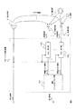
図1に、適応ビームフォーミングを備えた従来のエコー消去装置100の機能構成例を示す。エコー消去装置100は、N(Nは1以上の整数)個の収音手段(例えば、マイクロホン)に接続されている。エコー消去装置100は、N個のエコー消去部102n(n=1,...,N)と適応ビームフォーミング部104とを有する。また、以下の説明では、再生手段2から放出された再生信号をx(t)とし、再生信号x(t)が収音手段4nに回り込んだ信号をエコー信号a(t)とし、雑音源よりの雑音信号をb(t)とし、話者8からの話者信号をc(t)とする。エコー信号a(t)、雑音信号b(t)、話者信号c(t)からなる信号を収音信号とし、収音手段4nで収音された信号を収音信号をyn(t)と示し、エコー信号、雑音信号、話者信号をそれぞれan(t)bn(t)cn(t)と示す。tは離散時刻を示し、連続時間信号を一定のサンプル間隔Tでサンプリングしたことにより示されるものである。例えば、サンプリング周波数fs=48kHz(1秒間に48000回)とする。サンプリング周波数fs=1/Tである。また、エコー信号、雑音信号、話者信号が収音手段まで到達するまでは離散時刻ではなく、実時刻で表すべきであるが、説明簡略化のために、全て離散時刻tで示す。エコー消去装置100、以下で説明するエコー消去装置200、300においても離散時刻tで表された信号であるディジタル信号を扱うので、入力されるアナログ信号をDA変換器によりディジタル信号に変換し、出力するディジタル信号をAD変換器によりアナログ信号に変換する必要があるのであるが、このことは当然のことであるので、図1〜図3において、AD変換器、DA変換器については図示しない。また、雑音源6、話者8が存在しない場合は、収音信号には雑音信号、話者信号は含まれない。
FIG. 1 shows an example of the functional configuration of a conventional echo canceling apparatus 100 equipped with adaptive beamforming. The echo canceller 100 is connected to N (N is an integer of 1 or more) sound collecting means (for example, microphones). The echo cancellation apparatus 100 includes N echo cancellation units 102 n (n = 1,..., N) and an adaptive
説明を図1に戻す。収音信号yn(t)は、エコー消去部102nに入力される。エコー消去部102nは収音信号yn(t)からエコー信号an(t)を抑圧する。そして、エコー信号が消去された信号である残留エコー信号en(t)が適応ビームフォーミング部104に入力される。
Returning to FIG. The collected sound signal y n (t) is input to the echo canceller 102 n . Echo canceling unit 102 n may suppress the echo signal a n (t) from the sound collection signal y n (t). Then, the residual echo signal e n is a signal that the echo signal is erased (t) is input to the
適応ビームフォーミング部104はN個の残留エコー信号en(t)(=1,...,N)から雑音信号を抑圧し、出力信号z(t)として出力する。エコー消去部102n、適応ビームフォーミング部104の詳細な処理については、以下の「発明を実施するための最良の形態」で説明する。
エコー消去装置100の構成は、N個のエコー消去部102nの後段に適応ビームフォーミング部104を設置している。従って、適応ビームフォーミング部104の適応ビームフォーミングによる音響的指向性の変動をエコー消去部102nのエコー経路モデルに含まないようにできる。
Configuration of the echo canceller 100 is set up adaptive
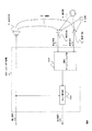
次に、図2に、適応ビームフォーミングを備えた従来のエコー消去装置200の機能構成例を示す。エコー消去装置200の構成は、適応ビームフォーミング部202が前段に、エコー消去部204が後段に設けられる。このように構成することで、適応ビームフォーミング部202よりの出力信号が1つである場合には、エコー消去部204は、その出力信号に対して1回のエコー消去処理(適応フィルタ処理)を行うだけでよく、低演算・低メモリ量の構成となっている。
上記エコー消去装置100の構成であると、計算コストの高いエコー消去部102nを収音手段の数であるN個分、備える必要があるため、膨大な計算コストが必要であった。また、上記エコー消去装置200の構成であると、エコー消去部のエコー経路モデルにおいて、時変ビームフォーミングを考慮しなければならないため、適応ビームフォーミング部202によって音響的指向性の変動が生じれば、エコー消去部204がエコー経路モデル(適応フィルタ)の再推定を行わなければならず、所望のエコー消去量に達しない場合がある。
With the configuration of the echo canceling apparatus 100, it is necessary to provide the echo canceling unit 102 n having a high calculation cost for the number N of the sound collecting means, which requires a huge calculation cost. Also, with the configuration of the echo canceller 200, time-varying beamforming must be taken into account in the echo path model of the echo canceler, so that if the
この発明の目的は、(1)計算コストを少なくし、(2)エコー消去部の所望エコー消去量に達するまでの時間を短くすることで、適応ビームフォーミング処理による音響的指向性の変動に関わらず、所望のエコー消去量に達するエコー消去装置を提供することである。 The object of the present invention is to (1) reduce the calculation cost, and (2) reduce the time required to reach the desired echo cancellation amount of the echo cancellation unit, thereby reducing the acoustic directivity due to adaptive beamforming processing. It is another object of the present invention to provide an echo canceling device that reaches a desired echo canceling amount.
この発明のエコー消去装置は、N個の収音手段で収音された収音信号に含まれるエコー信号を消去し、当該収音信号に含まれる雑音信号を抑圧して、出力信号として出力するものである。そして当該エコー消去装置は、N個の低域エコー消去部と、適応ビームフォーミング部と、エコー消去部と、を有する。低域エコー消去部は、収音信号の、予め定められた基準値より低い周波数帯域に含まれるエコー信号の成分を消去し、残留エコー信号を出力する。適応ビームフォーミング部は、N個の残留エコー信号から雑音信号を抑圧して、適応ビームフォーミング信号を出力する。エコー消去部は、適応ビームフォーミング信号から、エコー信号を消去することで出力信号を出力する。 The echo canceller of the present invention cancels an echo signal included in a sound pickup signal picked up by N sound pickup means, suppresses a noise signal included in the sound pickup signal, and outputs it as an output signal. Is. The echo cancellation apparatus includes N low-frequency echo cancellation units, an adaptive beam forming unit, and an echo cancellation unit. The low-frequency echo canceling unit cancels a component of the echo signal included in a frequency band lower than a predetermined reference value of the collected sound signal, and outputs a residual echo signal. The adaptive beamforming unit suppresses the noise signal from the N residual echo signals and outputs an adaptive beamforming signal. The echo canceller outputs an output signal by canceling the echo signal from the adaptive beamforming signal.
この発明では、パワーが低周波数帯域(以下、単に「低域」という。)に集中する話者音声の性質から低周波数帯域の所望エコー消去量が高周波数帯域(以下、単に「高域」という。)の所望エコー消去量より大きいことに着目する。そして、N個の低域エコー消去部は、入力された収音信号の予め定められた基準値より低い低域についてのみエコーを消去するので、エコー消去装置100中のN個のエコー消去部と比較して計算コストを削減できる。従って、エコー消去装置100の問題点を解決できる。 In the present invention, the desired echo cancellation amount in the low frequency band is referred to as the “high frequency” (hereinafter simply referred to as “high frequency”) because of the nature of the speaker voice in which power is concentrated in the low frequency band (hereinafter simply referred to as “low frequency”). Note that it is larger than the desired echo cancellation amount of. Since the N low-frequency echo canceling units cancel echoes only for a low frequency lower than a predetermined reference value of the input sound pickup signal, N echo canceling units in the echo canceling device 100 Computational cost can be reduced in comparison. Therefore, the problem of the echo canceller 100 can be solved.
また、この発明のエコー消去装置の構成は、前段からN個の低域エコー消去部、低域ビームフォーミング部、エコー消去部、の順番で構成されている。従って、低域エコー消去部のエコー経路モデルでは、適応ビームフォーミング部104の音響的指向性の変動による再推定を回避できる。また、エコー消去部については、低域エコー消去部によって、低域のエコーを消去したもの、つまり、大半のエコー信号の成分が消去された信号(適応ビームフォーミング信号)についてエコー信号の成分を消去する。従って、エコー消去部内で用いる全域残留エコー信号のパワーを最初から小さくでき、結果として、エコー消去部の所望エコー消去量に達するまでの時間を短くできる。よって、適応ビームフォーミング部による音響指向性変動が生じたとしても、エコー消去部は安定的に所望のエコー消去量を達成できる。また、上記非特許文献1には、エコー消去技術、適応ビームフォーミング技術のそれぞれの処理手順については記載されていない。
The echo canceling apparatus according to the present invention is configured in the order of N low-frequency echo canceling units, a low-frequency beam forming unit, and an echo canceling unit from the previous stage. Therefore, in the echo path model of the low-frequency echo canceling unit, re-estimation due to a change in acoustic directivity of the
以下に、発明を実施するための最良の形態を示す。なお、同じ機能を持つ構成部や同じ処理を行う過程には同じ番号を付し、重複説明を省略する。 The best mode for carrying out the invention will be described below. In addition, the same number is attached | subjected to the process which performs the structure part which has the same function, and the same process, and duplication description is abbreviate | omitted.
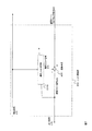
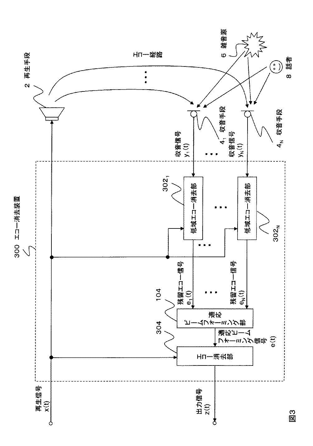
図3にエコー消去装置300の機能構成例を示し、図4に処理フローを示す。エコー消去装置300はN個の低域エコー消去部302n、適応ビームフォーミング部104、エコー消去部304を有する。図5に低域エコー消去部302nの機能構成例を示し、図6に適応ビームフォーミング部104の機能構成例を示し、図7にエコー消去部304の機能構成例を示す。なお、全ての低域エコー消去部302n(n=1,...,N)の構成手段は全て同じであるので、図5記載の各構成手段の参照番号については添え字「n」を省略している。また、エコー消去部304は、図2記載のエコー消去部204と同一である。
FIG. 3 shows a functional configuration example of the echo canceller 300, and FIG. 4 shows a processing flow. The echo cancellation apparatus 300 includes N low-frequency
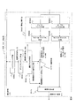
図5記載のように、この実施例の低域エコー消去部302は、ローパスフィルタ手段3014と、ダウンサンプリング手段3016と、適応フィルタ手段3018と、帯域分割手段3012と、減算手段3020と、帯域合成手段3022と、により構成される。帯域分割手段3012は、ローパスフィルタ手段30122、ハイパスフィルタ手段30124、2つのダウンサンプリング手段30126により構成される。また、図6記載のように、この実施例の適応ビームフォーミング部104は、周波数領域変換手段1042と、適応ビームフォーミング手段1044と、時間領域変換手段1046と、インパルス応答記憶部1050(またはステアリングベクトル記憶部1048)と、により構成される。また、図7記載のように、この実施例のエコー消去部304は、適応フィルタ手段3048、減算手段3051、により構成される。
As shown in FIG. 5, the low-frequency
[低域エコー消去部302nの処理(ステップS102)]
まず、収音信号yn(t)が、低域エコー消去部302nに入力される。エコー消去部302nは、収音信号yn(t)の予め定められた基準値αより低い周波数帯域に含まれるエコー信号an(t)の成分を消去し、残留エコー信号en(t)を出力する。まず、基準値αについて説明する。この発明では、パワーが低域に集中する話者音声の性質から、低域の所望エコー消去量が高域の所望エコー消去量より大きいことに着目する。例えば、全周波数帯域を24kHzとすると、再生信号の周波数帯域12kHz未満に話者音声は集中する場合が多く、結果として、収音信号の周波数帯域12kHz未満に含まれるエコー信号の成分を消去すれば、大半のエコー信号の成分を消去できることになる。基準値αとは、エコー信号の元となる信号(例えば、話者音声の信号)が集中している帯域の上限の周波数値を示すものである。基準値αは予め定められるものであり、上記の例ではα=12kHzとなる。このように、低域エコー消去部302nは、計算コスト削減のために、低域の収音信号yn(t)についてのみ、エコー消去処理を行う。この周波数帯域の基準値αは事前に設定しておけばよい。以下、低域エコー消去部302の処理を図5を用いて具体的に説明する。また、収音信号yn(t)について、低域エコー消去部302に入力される収音信号を説明簡略化のために「y(t)」と示す。
[Processing of low-frequency echo canceling unit 302 n (step S102)]
First, the collected sound signal y n (t) is input to the low-frequency
収音手段により収音され、入力された収音信号y(t)は、帯域分割手段3012中のローパスフィルタ手段30122およびハイパスフィルタ手段30124に入力される。ローパスフィルタ手段30122は収音信号y(t)に対して、ローパスフィルタ(上記の例では、12kHz未満の信号のみ通過させるもの)の係数を畳み込み、低域の収音信号yL(t)を出力する。
The collected sound signal y (t) collected and inputted by the sound collecting means is inputted to the low pass filter means 30122 and the high pass filter means 30124 in the band dividing means 3012. The low-
一方、ハイパスフィルタ手段30124は収音信号y(t)に対して、ハイパスフィルタ(上記の例では、12kHz以上の信号のみ通過させるもの)の係数を畳み込み、高域の収音信号yH(t)を出力する。ローパスフィルタ手段30122、ローパスフィルタ手段3014において、通過させる周波数帯域の基準値αを同一にすることが好ましい。
On the other hand, the high-pass filter means 30124 convolves the sound pickup signal y (t) with the coefficient of the high-pass filter (in the above example, only the signal of 12 kHz or higher is passed) to obtain the high-frequency sound pickup signal y H (t ) Is output. In the low-
低域収音信号yL(t)、高域収音信号yH(t)はそれぞれ、ダウンサンプリング手段30126、30128に入力される。そして、ダウンサンプリング手段30126は、低域収音信号yL(t)について、例えばM−1個、間引くダウンサンプリング処理を行う。間引き数Mは1以上の正の実数であり、例えば「2」とする。ダウンサンプリング処理後の信号をyL(Mt)と表す。同様に、ダウンサンプリング手段30128は、高域収音信号yH(t)について、例えばM−1個、間引くダウンサンプリング処理を行う。ダウンサンプリング処理後の信号をyH(Mt)と表す。低域収音信号yL(Mt)は減算手段3020に入力され、高域収音信号yH(Mt)は帯域合成手段3022に入力される。
The low-frequency sound collection signal y L (t) and the high-frequency sound collection signal y H (t) are input to the downsampling means 30126 and 30128, respectively. Then, the
一方、再生信号x(t)は、再生手段2およびローパスフィルタ手段3014に入力される。ローパスフィルタ手段3014は、ローパスフィルタ(上記の例では、12kHz未満の信号のみ通過させるもの)の係数を再生信号x(t)に対して畳み込むことで、再生信号x(t)の低域の信号(以下、「低域再生信号xL(t)」という。)を出力する。低域再生信号xL(t)はダウンサンプリング手段3016に入力される。ダウンサンプリング手段3016は、低域再生信号xL(t)について、M−1個、間引くダウンサンプリング処理を行う。ダウンサンプリング処理後の信号xL(Mt)は適応フィルタ手段3018に入力される。
On the other hand, the reproduction signal x (t) is input to the reproduction unit 2 and the low-
ここでダウンサンプリング手段3016、30126、30128によるダウンサンプリング処理については、元の標本化周波数より低くなればよい。有理数のダウンサンプリングに関しては、例えば、特願2007−262986号のアップダウンサンプリング装置とアップダウンサンプリング装置およびそのプログラムに詳細に記載されている。また、ダウンサンプリング手段3016、30126、30128は無くても良い。 Here, the downsampling processing by the downsampling means 3016, 30126, and 30128 may be lower than the original sampling frequency. The rational downsampling is described in detail in, for example, the up / down sampling apparatus and the up / down sampling apparatus of Japanese Patent Application No. 2007-262986 and the program thereof. Further, the downsampling means 3016, 30126, 30128 may be omitted.
適応フィルタ手段3018は、低域再生信号xL(Mt)に適応フィルタの係数hL(Mt)を畳み込むことで、低域擬似エコー信号dL(Mt)を出力する。当該畳み込みの式は以下のようになる。
![]()
![]()
減算手段3020は、低域収音信号yL(Mt)と、低域擬似エコー信号dL(Mt)との差をとることで、低域残留エコー信号eL(Mt)を出力する。図5の例では、低域収音信号yL(Mt)から低域擬似エコー信号dL(Mt)が差し引かれる。低域残留エコー信号eL(Mt)は帯域合成手段3022および適応フィルタ手段3018に入力される。適応フィルタ手段3018の適応フィルタの係数は、低域再生信号xL(Mt)および過去の低域残留エコー信号eL(Mt)により更新される。この更新については、様々なアルゴリズムが知られており、例えば、学習同定アルゴリズム(NLMS:Normalized Least-Mean-Squares)や指数重みつけアルゴリズムがあるが、念のため学習同定アルゴリズムについて簡単に説明する。学習同定アルゴリズムにより低域再生信号xL(Mt)のベクトルXL(Mt)を用いて、以下の式で適応フィルタ係数ベクトルHL(Mt)は更新される。
![]()
XL(Mt)=[xL(Mt)、xL(M(t−1))、...、xL(M(t−S+1))]
HL(Mt)=[hL、0(Mt)、hL、1(Mt)、...、hL、S−1(Mt)]であり、βはスカラ量のステップサイズであって、取りうる範囲は0<β<2である。また、δは分母が0になることを防止するための微小な定数である。<学習同定アルゴリズムの説明は以上>
The subtracting means 3020 outputs a low-frequency residual echo signal e L (Mt) by taking the difference between the low-frequency sound collection signal y L (Mt) and the low-frequency pseudo echo signal d L (Mt). In the example of FIG. 5, the low-frequency pseudo echo signal d L (Mt) is subtracted from the low-frequency sound collection signal y L (Mt). The low band residual echo signal e L (Mt) is input to the
![]()
X L (Mt) = [x L (Mt), x L (M (t−1)),. . . , X L (M (t−S + 1))]
H L (Mt) = [h L, 0 (Mt), h L, 1 (Mt),. . . , H L, S-1 (Mt)], β is the step size of the scalar quantity, and the possible range is 0 <β <2. Further, δ is a minute constant for preventing the denominator from becoming zero. <End of description of learning identification algorithm>
帯域合成手段3022は、低域残留エコー信号eL(Mt)と高域収音信号yH(Mt)について、帯域合成を行うことで、残留エコー信号e(t)を出力する。処理の詳細の具体例として、低域残留エコー信号eL(Mt)と高域収音信号yH(Mt)に対して、サンプル間にM−1個の零値を挿入し、アップサンプルで生じるイメージング(アップサンプリングする前のサンプリング周波数の折り返しスペクトル)を取り除くフィルタを畳み込んだそれぞれの出力信号を加算することで、残留エコー信号e(t)を出力する。そして、上記の処理が全ての低域エコー消去部302n(n=1,...,N)で行われ、それぞれの低域エコー消去部302nから残留エコー信号en(t)が出力される。
The
[適応ビームフォーミング部104の処理(ステップS104)]
全てのN個の残留エコー信号en(t)(n=1,...,N)は、適応ビームフォーミング部104に入力される。適応ビームフォーミング部104は、N個の残留エコー信号en(t)から雑音信号を抑圧して、適応ビームフォーミング信号s(t)を出力する。以下、図6を用いて具体例を説明する。なお、以下の適応ビームフォーミング部104の説明の詳細については、特開2008−60635号の段落[0004]〜[0010]等に記載されている。
[Processing of Adaptive Beamforming Unit 104 (Step S104)]
All N residual echo signals e n (t) (n = 1,..., N) are input to the
入力されたN個の残留エコー信号en(t)は周波数領域変換手段1042に入力される。周波数領域変換手段1042は、時間領域の信号である残留エコー信号en(t)を周波数領域信号En(f、τ)に変換する。ここで、fは周波数を示し、τは任意の時間を示す。周波数領域の変換については、公知の技術であるフーリエ変換などを用いればよい。En(f、τ)(n=1,...,N)は全て適応ビームフォーミング手段1044に入力される。
The input N residual echo signals e n (t) are input to the frequency
適応ビームフォーミング手段1044は、目的信号である話者信号c(t)を強調し、不要信号である雑音信号b(t)をできるだけ抑圧するフィルタ(W1(f)、...、WN(f)]Tを推定することで実現される。適応ビームフォーミング手段1044を設計する際には、「話者から各収音手段へのインパルス応答ベクトルg(f)もしくは、g(f)の近似であるステアリングベクトルa(f)=[exp(−i2πfτ1),...,exp(−i2πfτN)]Tが既知である」ということを仮定する。ここでτnは話者8よりの話者信号(目的信号)が収音手段nに達する時刻と原点0に達する時間差である。そして、図8に示すように収音手段4nを直線状に配置させることが多い。話者8の方向をθとし、収音s手段41を基準(原点)とした場合の収音手段4nの座標dnとすると、上述のτnは、τn=dncosθ/cで与えられる。ここでcは信号の速度である。 The adaptive beamforming means 1044 emphasizes the speaker signal c (t) as the target signal and suppresses the noise signal b (t) as the unnecessary signal as much as possible (W 1 (f),..., W N. (F)] This is realized by estimating T. When designing the adaptive beamforming means 1044, the impulse response vector g (f) from the speaker to each sound collection means or g (f) It is assumed that the steering vector a (f) = [exp (−i2πfτ 1 ),..., Exp (−i2πfτ N )] T is known ”, where τ n is from speaker 8. speaker signal (target signal) is the time difference reaches a time and origin 0 reaching the sound collection unit n. Then, it is often to linearly arranged a sound collecting means 4 n as shown in FIG. speaker The direction of 8 is θ, and sound collecting s means 4 1 When coordinates d n of the sound pickup means 4 n in the case of a reference (origin) of, tau n described above is given by τ n = d n cosθ / c . Where c is the signal rate of .
図6に説明を戻すと、不要信号を抑圧する適応ビームフォーミング手段1044として、以下の式で表される出力パワーA(W(f))を最小にする適応フィルタ群(ベクトル)1048n(n=1,...,N)であるW(f)=[W1(f),...,WN(f)]を推定する。
A(W(f))=V{|S|2(f、τ)}
=V{S(f、τ)S*(f、τ)}
=V{WT(f)E(f、τ)ET(f、τ)W(f)}
=WT(f)RE(f)W(f) (1)
Returning to FIG. 6, as adaptive beamforming means 1044 for suppressing unnecessary signals, an adaptive filter group (vector) 1048 n (n) that minimizes output power A (W (f)) expressed by the following equation. = 1,..., N) W (f) = [W 1 (f),. . . , W N (f)].
A (W (f)) = V {| S | 2 (f, τ)}
= V {S (f, τ) S * (f, τ)}
= V {W T (f) E (f, τ) E T (f, τ) W (f)}
= W T (f) R E (f) W (f) (1)
ここで、V{}は時間τに関する平均操作、A*はAの複素共役、RE(f)=V{E(f、τ)ET(f、τ)}は入力信号の相関行列、S(f、τ)は適応ビームフォーミング手段1044の出力であり、以下の式で表すことが出来る。
S(f、τ)=WT(f)E(f、τ) (2)
ここで、意味のない解(W(f)=0=[0、...、0]T)を回避するために、目的信号が無歪みで得られるという以下の式に示す拘束条件を付与する。
WT(f)g(f)=1 (3)
Here, V {} is an average operation with respect to time τ, A * is a complex conjugate of A, R E (f) = V {E (f, τ) E T (f, τ)} is a correlation matrix of an input signal, S (f, τ) is an output of the adaptive beamforming means 1044 and can be expressed by the following equation.
S (f, τ) = W T (f) E (f, τ) (2)
Here, in order to avoid a meaningless solution (W (f) = 0 = [0,..., 0] T ), the constraint condition shown in the following equation is given that the target signal can be obtained without distortion. To do.
W T (f) g (f) = 1 (3)
これにより、式(3)を満たし、かつ上記式(1)のA(W(f))の値が最小となるW(f)の値を求める問題はLagurangeの未定乗数pを用いて、以下の式(4)で表すことができる。
A’(W(f))=A(W(f))+p(WT(f)g(f)−1)(4)
式(4)を解くことにより、適応フィルタ群(ベクトル)W(f)は、以下の式(5)で得られる。
A ′ (W (f)) = A (W (f)) + p (W T (f) g (f) −1) (4)
By solving equation (4), the adaptive filter group (vector) W (f) is obtained by the following equation (5).
適応ビームフォーミング手段1044から出力された周波数領域の適応ビームフォーミング信号S(f、τ)は時間領域変換手段1046に入力される。時間領域変換手段1046は、例えば公知の技術である逆フーリエ変換などを用いて、周波数領域の信号である適応ビームフォーミング信号S(f、τ)を時間領域の適応ビームフォーミング信号s(t)に変換して出力する。
The frequency domain adaptive beamforming signal S (f, τ) output from the adaptive beamforming means 1044 is input to the time
[エコー消去部304の処理(ステップS106)]
適応ビームフォーミング信号s(t)は、エコー消去部304に入力される。エコー消去部304は、適応ビームフォーミング信号s(t)から、エコー信号を消去することで、出力信号z(t)として出力する。エコー消去部304の処理内容は公知であるが、図7を用いて念のため説明する。
[Processing of Echo Erasing Unit 304 (Step S106)]
The adaptive beamforming signal s (t) is input to the
再生信号x(t)は、適応フィルタ手段3048に入力される。適応フィルタ手段3048は、以下の式のように、再生信号x(t)に適応フィルタの係数h(t)を畳み込むことで擬似エコー信号のベクトルd(t)を出力する。
![]()
![]()
そして、減算手段3051は、適応ビームフォーミング信号s(t)から擬似エコー信号d(t)差し引くことで、残留エコー信号e(t)を出力する。そして、適応フィルタ手段3048の適応フィルタのベクトルは、過去の残留エコー信号と再生信号により、上述した学習同定法等を用いて更新される。 Then, the subtracting means 3051 outputs a residual echo signal e (t) by subtracting the pseudo echo signal d (t) from the adaptive beamforming signal s (t). Then, the vector of the adaptive filter of the adaptive filter means 3048 is updated by using the above-described learning identification method or the like with the past residual echo signal and the reproduced signal.
ここで、N個の低域エコー消去部302nにより、収音信号の低周波数帯域に含まれるエコー信号の成分は消去されており、つまり、適応ビームフォーミング信号に含まれるエコー信号の成分は大半が消去されているので、残留エコー信号e(t)のパワーはかなり小さくなる。従って、所望エコー消去量に達するまでの時間を短くでき、適応ビームフォーミング部104の音響的指向性の変動が生じたとしても、所望のエコー消去量に達することが出来る。
Here, the components of the echo signal included in the low frequency band of the collected sound signal are canceled by the N low-frequency
そして、残留エコー信号e(t)は出力信号z(t)として出力される。また、話者信号c(t)が存在する場合には、残留エコー信号e(t)と話者信号c(t)とが出力信号z(t)として出力される。 The residual echo signal e (t) is output as an output signal z (t). When the speaker signal c (t) is present, the residual echo signal e (t) and the speaker signal c (t) are output as the output signal z (t).
実施例1のエコー消去部304は入力信号の全周波数帯域についてエコー信号の成分を消去した。しかし、N個の低域エコー消去部302nで、低域のエコー信号の成分を消去されているので、エコー消去部では、基準値α(上記の例ではα=12kHz)より高い周波数帯域の適応ビームフォーミング信号から、エコー信号を消去するようにしてもよい。このようにすることで、エコー消去部の計算コストを大幅に削減できる。この場合のエコー消去部の参照符号を306とし、エコー消去部306の機能構成例を図9に示す。エコー消去部306は低域エコー消去部302(図5参照)のハイパスフィルタ手段とローパスフィルタ手段とを入れ替えた構成になっている。エコー消去部306の処理内容を簡単に説明する。
The
まず、適応ビームフォーミング信号s(t)が、帯域分割手段3062中のハイパスフィルタ手段30622およびローパスフィルタ手段30624に入力される。ハイパスフィルタ手段30622は適応ビームフォーミングs(t)に対して、ハイパスフィルタ(上記の例では、12kHz(=基準値α)以上の信号のみ通過させるもの)の係数を畳み込み、高域の適応ビームフォーミング信号sH(t)を出力する。ローパスフィルタ手段30624は適応ビームフォーミング信号s(t)に対して、ローパスフィルタ(上記の例では、12kHz未満の信号のみ通過させるもの)の係数を畳み込み、低域の適応ビームフォーミング信号sL(t)を出力する。
First, adaptive beamforming signal s (t) is input to high-pass filter means 30622 and low-pass filter means 30624 in band dividing means 3062. The high-pass filter means 30622 convolves the adaptive beamforming s (t) with a coefficient of a high-pass filter (in the above example, only a signal having a frequency of 12 kHz (= reference value α) or higher) is passed, and high-frequency adaptive beamforming is performed. The signal s H (t) is output. The low-
高域適応ビームフォーミング信号sH(t)、低域適応ビームフォーミング信号sL(t)、はそれぞれ、ダウンサンプリング手段30626、30628に入力される。そして、ダウンサンプリング手段30626、30628はそれぞれ、高域適応ビームフォーミング信号sH(t)、低域適応ビームフォーミング信号sL(t)について、ダウンサンプリング処理を行う。ダウンサンプリング処理後の高域適応ビームフォーミング信号sH(Mt)は、減算手段3070に入力され、ダウンサンプリング処理後の低域適応ビームフォーミング信号sL(Mt)は、帯域合成手段3072に入力される。
The high-frequency adaptive beamforming signal s H (t) and the low-frequency adaptive beamforming signal s L (t) are input to downsampling means 30626 and 30628, respectively. Then, the downsampling means 30626 and 30628 respectively perform downsampling processing on the high frequency adaptive beamforming signal s H (t) and the low frequency adaptive beamforming signal s L (t). The high frequency adaptive beamforming signal s H (Mt) after the downsampling process is input to the subtracting unit 3070, and the low frequency adaptive beamforming signal s L (Mt) after the downsampling process is input to the
一方、ハイパスフィルタ手段3064は、再生信号x(t)に対して、ハイパスフィルタ(上記の例では、12kHz(=基準値α)以上の信号のみ通過させるもの)の係数を再生信号x(t)に対して畳み込むことで、高域再生信号xH(t)を出力する。高域再生信号xH(t)はダウンサンプリング手段3066に入力される。ダウンサンプリング手段3066は、高域再生信号xH(t)について、ダウンサンプリング処理を行う。ダウンサンプリング処理後の信号xH(Mt)は適応フィルタ手段3068に入力される。また、ダウンサンプリング手段3066、30626、30628は無くても良い。 On the other hand, the high-pass filter means 3064 applies the coefficient of the high-pass filter (in the above example, only the signal of 12 kHz (= reference value α) or higher) to the reproduction signal x (t) with respect to the reproduction signal x (t). Is output as a high-frequency reproduction signal x H (t). The high frequency reproduction signal x H (t) is input to the downsampling means 3066. The downsampling means 3066 performs a downsampling process on the high frequency reproduction signal x H (t). The signal x H (Mt) after the downsampling process is input to the adaptive filter means 3068. Further, the downsampling means 3066, 30626, and 30628 may be omitted.
適応フィルタ手段3068は、低域再生信号に適応フィルタを畳み込むことで、高域擬似エコー信号dH(Mt)を出力する。減算手段3070は、高域適応ビームフォーミング信号sH(Mt)から高域擬似エコー信号dH(Mt)を差し引くことで、高域残留エコー信号eH(Mt)を出力する。高域残留エコー信号eH(Mt)は帯域合成手段3072および適応フィルタ手段3068に入力される。適応フィルタ手段3068の適応フィルタ係数は、高域再生信号xH(Mt)および過去の高域残留エコー信号eH(Mt)により、上記学習同定アルゴリズム等を用いて、更新される。
The adaptive filter means 3068 outputs a high-frequency pseudo echo signal d H (Mt) by convolving an adaptive filter with the low-frequency reproduction signal. The subtracting unit 3070 outputs a high-frequency residual echo signal e H (Mt) by subtracting the high-frequency pseudo echo signal d H (Mt) from the high-frequency adaptive beamforming signal s H (Mt). The high-frequency residual echo signal e H (Mt) is input to the
帯域合成手段3072は、高域残留エコー信号eH(Mt)と低域適応ビームフォーミング信号sL(Mt)について、帯域合成およびアップサンプリング処理を行うことで、残留エコー信号e(t)を出力する。帯域合成手段3072の処理の詳細は、帯域合成手段3022の処理と同様なので、省略する。そして、帯域合成手段3072から残留エコー信号e(t)が、出力信号z(t)として出力される。<エコー消去部306の処理の説明以上>
The
上記のエコー消去装置300は、再生手段2が1つの場合について説明したが、再生手段が2以上の場合であっても、適用できる。
また、低域エコー消去部302n、エコー消去部304の処理は時間領域で行い、適応ビームフォーミング部104の処理は周波数領域で行った例を説明した。しかし、低域エコー消去部302n、エコー消去部304の処理を周波数領域で行い、適応ビームフォーミング部104の処理は時間領域で行ってもよい。
The above-described echo canceling apparatus 300 has been described with respect to the case where there is one reproducing unit 2, but the present invention can be applied even when there are two or more reproducing units.
Further, an example has been described in which the processing of the low-frequency
この発明では、パワーが低域に集中する話者音声の性質から、低域の所望エコー消去量が高域の所望エコー消去量より大きいことに着目する。そして、本実施例のエコー消去装置は、「低域エコー消去部302nによる低域のエコー消去処理」→「適応ビームフォーミング部104による適応ビームフォーミング処理」→「エコー消去部304によるエコー消去」、の順番で処理を行う。まず、低域エコー消去部302nは、収音信号の低周波数帯域のみに含まれるエコー信号の成分を消去する。従って、エコー消去装置100よりも計算コストを削減できる。また、適応ビームフォーミング処理の前に、低域のエコー消去処理を行う。従って、低域エコー消去部のエコー経路モデルでは、適応ビームフォーミング部104の音響的指向性の変動による再推定を回避できる。また、低域のエコー消去処理により収音信号に含まれる大半のエコー信号の成分を消去している。従って、エコー消去部304中の減算手段3051よりの残留エコー信号e(t)のパワーは小さいものとなり、結果として、エコー消去部の所望エコー消去量に達するまでの時間を短くできる。よって、適応ビームフォーミング部104による音響的指向特性の変動が生じたとしても、所望のエコー消去量に達することが出来る。
In the present invention, attention is paid to the fact that the low-frequency desired echo cancellation amount is larger than the high-frequency desired echo cancellation amount due to the nature of the speaker voice whose power is concentrated in the low frequency range. The echo canceling apparatus according to the present embodiment is “low-frequency echo canceling processing by the low-frequency
また、この実施例1のエコー消去装置300が従来のエコー消去装置100よりも優れていることを示す実験結果について説明する。マイクロホン数N=4とし、全周波数帯域を24kHzとし、周波数帯域の基準値α=12kHz、つまり、低域を12kHz未満、高域を12〜24kHzとした場合に、本実施例のエコー消去装置300の計算コストは、エコー消去装置100のエコー消去処理にかかる計算コストより約40%削減できる。 An experimental result showing that the echo canceling apparatus 300 of the first embodiment is superior to the conventional echo canceling apparatus 100 will be described. When the number of microphones is N = 4, the entire frequency band is 24 kHz, the reference value α of the frequency band is 12 kHz, that is, the low band is less than 12 kHz and the high band is 12 to 24 kHz, the echo canceling apparatus 300 of this embodiment is used. This calculation cost can be reduced by about 40% from the calculation cost for the echo cancellation processing of the echo cancellation apparatus 100.
<ハードウェア構成>
本発明は上述の実施の形態に限定されるものではない。また、上述の各種の処理は、記載に従って時系列に実行されるのみならず、処理を実行する装置の処理能力あるいは必要に応じて並列的にあるいは個別に実行されてもよい。その他、本発明の趣旨を逸脱しない範囲で適宜変更が可能であることはいうまでもない。
また、上述の構成をコンピュータによって実現する場合、エコー消去装置300が有すべき機能の処理内容はプログラムによって記述される。そして、このプログラムをコンピュータで実行することにより、処理機能がコンピュータ上で実現される。
<Hardware configuration>
The present invention is not limited to the above-described embodiment. In addition, the various processes described above are not only executed in time series according to the description, but may be executed in parallel or individually according to the processing capability of the apparatus that executes the processes or as necessary. Needless to say, other modifications are possible without departing from the spirit of the present invention.
Further, when the above-described configuration is realized by a computer, processing contents of functions that the echo canceling apparatus 300 should have are described by a program. The processing function is realized on the computer by executing the program on the computer.
この処理内容を記述したプログラムは、コンピュータで読み取り可能な記録媒体に記録しておくことができる。コンピュータで読み取り可能な記録媒体としては、例えば、磁気記録装置、光ディスク、光磁気記録媒体、半導体メモリ等どのようなものでもよいが、具体的には、例えば、磁気記録装置として、ハードディスク装置、フレキシブルディスク、磁気テープ等を、光ディスクとして、DVD(Digital Versatile Disc)、DVD−RAM(Random Access Memory)、CD−ROM(Compact Disc Read Only Memory)、CD−R(Recordable)/RW(ReWritable)等を、光磁気記録媒体として、MO(Magneto-Optical disc)等を、半導体メモリとしてEEP−ROM(Electronically Erasable and Programmable-Read Only Memory)等を用いることができる。 The program describing the processing contents can be recorded on a computer-readable recording medium. The computer-readable recording medium may be any medium such as a magnetic recording device, an optical disk, a magneto-optical recording medium, or a semiconductor memory. Specifically, for example, the magnetic recording device may be a hard disk device or a flexible Discs, magnetic tapes, etc. as optical disks, DVD (Digital Versatile Disc), DVD-RAM (Random Access Memory), CD-ROM (Compact Disc Read Only Memory), CD-R (Recordable) / RW (ReWritable), etc. As the magneto-optical recording medium, MO (Magneto-Optical disc) or the like can be used, and as the semiconductor memory, EEP-ROM (Electronically Erasable and Programmable-Read Only Memory) or the like can be used.
また、このプログラムの流通は、例えば、そのプログラムを記録したDVD、CD−ROM等の可搬型記録媒体を販売、譲渡、貸与等することによって行う。さらに、このプログラムをサーバコンピュータの記憶装置に格納しておき、ネットワークを介して、サーバコンピュータから他のコンピュータにそのプログラムを転送することにより、このプログラムを流通させる構成としてもよい。 The program is distributed by selling, transferring, or lending a portable recording medium such as a DVD or CD-ROM in which the program is recorded. Furthermore, the program may be distributed by storing the program in a storage device of the server computer and transferring the program from the server computer to another computer via a network.
このようなプログラムを実行するコンピュータは、例えば、まず、可搬型記録媒体に記録されたプログラムもしくはサーバコンピュータから転送されたプログラムを、一旦、自己の記憶装置に格納する。そして、処理の実行時、このコンピュータは、自己の記録媒体に格納されたプログラムを読み取り、読み取ったプログラムに従った処理を実行する。また、このプログラムの別の実行形態として、コンピュータが可搬型記録媒体から直接プログラムを読み取り、そのプログラムに従った処理を実行することとしてもよく、さらに、このコンピュータにサーバコンピュータからプログラムが転送されるたびに、逐次、受け取ったプログラムに従った処理を実行することとしてもよい。また、サーバコンピュータから、このコンピュータへのプログラムの転送は行わず、その実行指示と結果取得のみによって処理機能を実現する、いわゆるASP(Application Service Provider)型のサービスによって、上述の処理を実行する構成としてもよい。なお、本形態におけるプログラムには、電子計算機による処理の用に供する情報であってプログラムに準ずるもの(コンピュータに対する直接の指令ではないがコンピュータの処理を規定する性質を有するデータ等)を含むものとする。 A computer that executes such a program first stores, for example, a program recorded on a portable recording medium or a program transferred from a server computer in its storage device. When executing the process, the computer reads a program stored in its own recording medium and executes a process according to the read program. As another execution form of the program, the computer may directly read the program from a portable recording medium and execute processing according to the program, and the program is transferred from the server computer to the computer. Each time, the processing according to the received program may be executed sequentially. Also, the program is not transferred from the server computer to the computer, and the above-described processing is executed by a so-called ASP (Application Service Provider) type service that realizes the processing function only by the execution instruction and result acquisition. It is good. Note that the program in this embodiment includes information that is used for processing by an electronic computer and that conforms to the program (data that is not a direct command to the computer but has a property that defines the processing of the computer).
また、この形態では、コンピュータ上で所定のプログラムを実行させることにより、本装置を構成することとしたが、これらの処理内容の少なくとも一部をハードウェア的に実現することとしてもよい。
また、本実施例で説明したエコー消去装置300は、CPU(Central Processing Unit)、入力部、出力部、補助記憶装置、RAM(Random Access Memory)、ROM(Read Only Memory)及びバスを有している(何れも図示せず)。
CPUは、読み込まれた各種プログラムに従って様々な演算処理を実行する。補助記憶装置は、例えば、ハードディスク、MO(Magneto-Optical disc)、半導体メモリ等であり、RAMは、SRAM(Static Random Access Memory)、DRAM (Dynamic Random Access Memory)等である。また、バスは、CPU、入力部、出力部、補助記憶装置、RAM及びROMを通信可能に接続している。
In this embodiment, the present apparatus is configured by executing a predetermined program on a computer. However, at least a part of these processing contents may be realized by hardware.
The echo canceller 300 described in this embodiment includes a CPU (Central Processing Unit), an input unit, an output unit, an auxiliary storage device, a RAM (Random Access Memory), a ROM (Read Only Memory), and a bus. (Both not shown).
The CPU executes various arithmetic processes according to the read various programs. The auxiliary storage device is, for example, a hard disk, an MO (Magneto-Optical disc), a semiconductor memory, or the like, and the RAM is an SRAM (Static Random Access Memory), a DRAM (Dynamic Random Access Memory), or the like. The bus connects the CPU, the input unit, the output unit, the auxiliary storage device, the RAM, and the ROM so that they can communicate with each other.
<ハードウェアとソフトウェアとの協働>
本実施例の単語追加装置は、上述のようなハードウェアに所定のプログラムが読み込まれ、CPUがそれを実行することによって構築される。以下、このように構築される各装置の機能構成を説明する。
エコー消去装置300の低域エコー消去部302n、適応ビームフォーミング部104、エコー消去部304は、所定のプログラムがCPUに読み込まれ、実行されることによって構築される演算部である。エコー消去装置300の記憶部(図示せず)は上記補助記憶装置として機能する。
<Cooperation between hardware and software>
The word adding device of this embodiment is constructed by reading a predetermined program into the hardware as described above and executing it by the CPU. The functional configuration of each device constructed in this way will be described below.
The low-frequency
Claims (8)
それぞれが前記収音信号の、予め定められた基準値より低い周波数帯域に含まれるエコー信号の成分を消去し、残留エコー信号を出力するN個の低域エコー消去部と、
N個の前記残留エコー信号から前記雑音信号を抑圧して、適応ビームフォーミング信号を出力する適応ビームフォーミング部と、
前記適応ビームフォーミング信号から、エコー信号を消去することで前記出力信号を出力するエコー消去部と、
を有するエコー消去装置。 In an echo canceller that cancels an echo signal included in a sound pickup signal picked up by N sound pickup means, suppresses a noise signal included in the sound pickup signal, and outputs it as an output signal.
N low-frequency echo cancellers each canceling a component of an echo signal included in a frequency band lower than a predetermined reference value of the collected sound signal and outputting a residual echo signal;
An adaptive beamforming unit that suppresses the noise signal from N residual echo signals and outputs an adaptive beamforming signal;
An echo canceling unit that outputs the output signal by canceling an echo signal from the adaptive beamforming signal;
Echo canceller with
前記低域エコー消去部は、
前記再生信号の低域周波数帯の信号(以下、「低域再生信号」という。)を出力するローパスフィルタ手段と、
前記収音信号を帯域分割することで、低域収音信号と高域収音信号に分けて出力する帯域分割手段と、
前記低域再生信号に適応フィルタを畳み込むことで、低域擬似エコー信号を出力する適応フィルタ手段と、
前記低域収音信号と前記低域擬似エコー信号との差をとることで、低域残留エコー信号を出力する減算手段と、
前記低域残留エコー信号と前記高域収音信号について帯域合成を行うことで、前記残留エコー信号を出力する帯域合成手段と、を有し、
前記適応フィルタは、過去の低域残留エコー信号と前記低域再生信号とを用いて更新されることを特徴とするエコー消去装置。 The echo canceller according to claim 1,
The low-frequency echo canceller is
Low-pass filter means for outputting a signal in the low frequency band of the reproduction signal (hereinafter referred to as “low frequency reproduction signal”);
Band dividing means for dividing the sound collection signal into a low frequency sound collection signal and a high frequency sound collection signal by dividing the band,
Adaptive filter means for outputting a low-frequency pseudo echo signal by convolving an adaptive filter with the low-frequency reproduction signal;
Subtracting means for outputting a low-frequency residual echo signal by taking the difference between the low-frequency sound pickup signal and the low-frequency pseudo echo signal;
Band synthesis means for outputting the residual echo signal by performing band synthesis for the low-frequency residual echo signal and the high-frequency sound collection signal,
The adaptive filter is updated by using a past low-frequency residual echo signal and the low-frequency reproduction signal, and an echo canceller.
前記エコー消去部は、
前記基準値より高い周波数帯域の適応ビームフォーミング信号から、エコー信号を消去するものであることを特徴とするエコー消去装置。 The echo canceller according to claim 1 or 2, wherein
The echo canceller is
An echo canceller for canceling an echo signal from an adaptive beamforming signal in a frequency band higher than the reference value.
収音手段毎に、前記収音信号の予め定められた基準値より低い周波数帯域に含まれるエコー信号の成分を消去し、残留エコー信号を出力する低域エコー消去過程と、
N個の前記残留エコー信号から前記雑音信号を抑圧して、適応ビームフォーミング信号を出力する適応ビームフォーミング過程と、
前記適応ビームフォーミング信号から、エコー信号を消去することで前記出力信号を出力するエコー消去過程と、
を有するエコー消去方法。 In an echo canceling method of canceling an echo signal included in a sound pickup signal picked up by N sound pickup means, suppressing a noise signal included in the sound pickup signal, and outputting it as an output signal,
For each sound collection means, a low-frequency echo cancellation process for canceling the echo signal component included in a frequency band lower than a predetermined reference value of the sound collection signal and outputting a residual echo signal;
Adaptive beamforming process of suppressing the noise signal from the N residual echo signals and outputting an adaptive beamforming signal;
An echo cancellation process for outputting the output signal by canceling an echo signal from the adaptive beamforming signal;
An echo canceling method comprising:
前記低域エコー消去過程は、
前記再生信号の低域周波数帯の信号(以下、「低域再生信号」という。)を出力するローパスフィルタステップと、
前記収音信号を帯域分割することで、低域収音信号と高域収音信号に分けて出力する帯域分割ステップと、
前記低域再生信号に適応フィルタを畳み込むことで、低域擬似エコー信号を出力する適応フィルタステップと、
前記低域収音信号と前記低域擬似エコー信号との差をとることで、低域残留エコー信号を出力する減算ステップと、
前記低域残留エコー信号と前記高域収音信号について帯域合成を行うことで、前記残留エコー信号を出力する帯域合成ステップと、を有し、
前記適応フィルタは、過去の低域残留エコー信号と前記低域再生信号とを用いて更新されることを特徴とするエコー消去方法。 The echo cancellation method according to claim 4,
The low-frequency echo cancellation process includes:
A low-pass filter step of outputting a signal in a low frequency band of the reproduction signal (hereinafter referred to as “low frequency reproduction signal”);
By dividing the sound collection signal into bands, a band division step for outputting the sound collection signal divided into a low frequency sound collection signal and a high frequency sound collection signal,
An adaptive filter step of outputting a low-frequency pseudo echo signal by convolving an adaptive filter with the low-frequency reproduction signal;
A subtraction step of outputting a low-frequency residual echo signal by taking a difference between the low-frequency sound pickup signal and the low-frequency pseudo echo signal;
A band synthesis step of outputting the residual echo signal by performing band synthesis on the low-frequency residual echo signal and the high-frequency sound collection signal,
The adaptive filter is updated using a past low-frequency residual echo signal and the low-frequency reproduction signal, and an echo cancellation method characterized in that the adaptive filter is updated.
前記エコー消去過程は、
前記基準値より高い周波数帯域の適応ビームフォーミング信号から、エコー信号を消去することを特徴とするエコー消去方法。 The echo cancellation method according to claim 4 or 5,
The echo cancellation process includes:
An echo cancellation method comprising: canceling an echo signal from an adaptive beamforming signal in a frequency band higher than the reference value.
A computer-readable recording medium on which the program according to claim 7 is recorded.
Priority Applications (1)
| Application Number | Priority Date | Filing Date | Title |
|---|---|---|---|
| JP2008189910A JP5075042B2 (en) | 2008-07-23 | 2008-07-23 | Echo canceling apparatus, echo canceling method, program thereof, and recording medium |
Applications Claiming Priority (1)
| Application Number | Priority Date | Filing Date | Title |
|---|---|---|---|
| JP2008189910A JP5075042B2 (en) | 2008-07-23 | 2008-07-23 | Echo canceling apparatus, echo canceling method, program thereof, and recording medium |
Publications (2)
| Publication Number | Publication Date |
|---|---|
| JP2010028653A true JP2010028653A (en) | 2010-02-04 |
| JP5075042B2 JP5075042B2 (en) | 2012-11-14 |
Family
ID=41734023
Family Applications (1)
| Application Number | Title | Priority Date | Filing Date |
|---|---|---|---|
| JP2008189910A Expired - Fee Related JP5075042B2 (en) | 2008-07-23 | 2008-07-23 | Echo canceling apparatus, echo canceling method, program thereof, and recording medium |
Country Status (1)
| Country | Link |
|---|---|
| JP (1) | JP5075042B2 (en) |
Cited By (22)
| Publication number | Priority date | Publication date | Assignee | Title |
|---|---|---|---|---|
| WO2012138794A1 (en) * | 2011-04-04 | 2012-10-11 | Qualcomm Incorporated | Integrated echo cancellation and noise suppression |
| WO2013054448A1 (en) * | 2011-10-14 | 2013-04-18 | 富士通株式会社 | Sound processing device, sound processing method and program |
| US8711219B2 (en) | 2011-03-31 | 2014-04-29 | Kabushiki Kaisha Toshiba | Signal processor and signal processing method |
| JP2019004466A (en) * | 2017-06-12 | 2019-01-10 | ヤマハ・ユニファイド・コミュニケーションズ | Sound collection device, sound discharge and collection device, signal processing method, and program |
| US10367948B2 (en) | 2017-01-13 | 2019-07-30 | Shure Acquisition Holdings, Inc. | Post-mixing acoustic echo cancellation systems and methods |
| CN110085248A (en) * | 2012-08-24 | 2019-08-02 | 奥迪康有限公司 | Noise reduction and noise estimation when Echo cancellation in personal communication |
| WO2020121545A1 (en) * | 2018-12-14 | 2020-06-18 | 日本電信電話株式会社 | Signal processing device, signal processing method, and program |
| USD940116S1 (en) | 2015-04-30 | 2022-01-04 | Shure Acquisition Holdings, Inc. | Array microphone assembly |
| US11297423B2 (en) | 2018-06-15 | 2022-04-05 | Shure Acquisition Holdings, Inc. | Endfire linear array microphone |
| US11297426B2 (en) | 2019-08-23 | 2022-04-05 | Shure Acquisition Holdings, Inc. | One-dimensional array microphone with improved directivity |
| US11303981B2 (en) | 2019-03-21 | 2022-04-12 | Shure Acquisition Holdings, Inc. | Housings and associated design features for ceiling array microphones |
| US11302347B2 (en) | 2019-05-31 | 2022-04-12 | Shure Acquisition Holdings, Inc. | Low latency automixer integrated with voice and noise activity detection |
| US11310596B2 (en) | 2018-09-20 | 2022-04-19 | Shure Acquisition Holdings, Inc. | Adjustable lobe shape for array microphones |
| US11438691B2 (en) | 2019-03-21 | 2022-09-06 | Shure Acquisition Holdings, Inc. | Auto focus, auto focus within regions, and auto placement of beamformed microphone lobes with inhibition functionality |
| US11445294B2 (en) | 2019-05-23 | 2022-09-13 | Shure Acquisition Holdings, Inc. | Steerable speaker array, system, and method for the same |
| US11523212B2 (en) | 2018-06-01 | 2022-12-06 | Shure Acquisition Holdings, Inc. | Pattern-forming microphone array |
| US11552611B2 (en) | 2020-02-07 | 2023-01-10 | Shure Acquisition Holdings, Inc. | System and method for automatic adjustment of reference gain |
| US11558693B2 (en) | 2019-03-21 | 2023-01-17 | Shure Acquisition Holdings, Inc. | Auto focus, auto focus within regions, and auto placement of beamformed microphone lobes with inhibition and voice activity detection functionality |
| US11678109B2 (en) | 2015-04-30 | 2023-06-13 | Shure Acquisition Holdings, Inc. | Offset cartridge microphones |
| US11706562B2 (en) | 2020-05-29 | 2023-07-18 | Shure Acquisition Holdings, Inc. | Transducer steering and configuration systems and methods using a local positioning system |
| US11785380B2 (en) | 2021-01-28 | 2023-10-10 | Shure Acquisition Holdings, Inc. | Hybrid audio beamforming system |
| CN116962934A (en) * | 2023-09-19 | 2023-10-27 | 九音科技(南京)有限公司 | Pickup noise reduction method and system |
Families Citing this family (1)
| Publication number | Priority date | Publication date | Assignee | Title |
|---|---|---|---|---|
| ES2943483T3 (en) * | 2017-11-14 | 2023-06-13 | Nippon Telegraph & Telephone | Voice communication device, voice communication method, and program |
Citations (4)
| Publication number | Priority date | Publication date | Assignee | Title |
|---|---|---|---|---|
| JPH08321796A (en) * | 1995-05-26 | 1996-12-03 | Hitachi Ltd | Acoustic echo canceller |
| JP2002076998A (en) * | 2000-08-25 | 2002-03-15 | Oki Electric Ind Co Ltd | Echo and noise cancellor |
| JP2003316400A (en) * | 2002-04-24 | 2003-11-07 | Toshiba Corp | Voice signal processor and voice signal processing method |
| JP2007181099A (en) * | 2005-12-28 | 2007-07-12 | Yamaha Corp | Voice playing and picking-up apparatus |
-
2008
- 2008-07-23 JP JP2008189910A patent/JP5075042B2/en not_active Expired - Fee Related
Patent Citations (4)
| Publication number | Priority date | Publication date | Assignee | Title |
|---|---|---|---|---|
| JPH08321796A (en) * | 1995-05-26 | 1996-12-03 | Hitachi Ltd | Acoustic echo canceller |
| JP2002076998A (en) * | 2000-08-25 | 2002-03-15 | Oki Electric Ind Co Ltd | Echo and noise cancellor |
| JP2003316400A (en) * | 2002-04-24 | 2003-11-07 | Toshiba Corp | Voice signal processor and voice signal processing method |
| JP2007181099A (en) * | 2005-12-28 | 2007-07-12 | Yamaha Corp | Voice playing and picking-up apparatus |
Cited By (38)
| Publication number | Priority date | Publication date | Assignee | Title |
|---|---|---|---|---|
| US8711219B2 (en) | 2011-03-31 | 2014-04-29 | Kabushiki Kaisha Toshiba | Signal processor and signal processing method |
| US8811601B2 (en) | 2011-04-04 | 2014-08-19 | Qualcomm Incorporated | Integrated echo cancellation and noise suppression |
| WO2012138794A1 (en) * | 2011-04-04 | 2012-10-11 | Qualcomm Incorporated | Integrated echo cancellation and noise suppression |
| US9485572B2 (en) | 2011-10-14 | 2016-11-01 | Fujitsu Limited | Sound processing device, sound processing method, and program |
| JPWO2013054448A1 (en) * | 2011-10-14 | 2015-03-30 | 富士通株式会社 | Sound processing apparatus, sound processing method and program |
| EP2768242A4 (en) * | 2011-10-14 | 2015-04-29 | Fujitsu Ltd | Sound processing device, sound processing method and program |
| WO2013054448A1 (en) * | 2011-10-14 | 2013-04-18 | 富士通株式会社 | Sound processing device, sound processing method and program |
| CN110085248A (en) * | 2012-08-24 | 2019-08-02 | 奥迪康有限公司 | Noise reduction and noise estimation when Echo cancellation in personal communication |
| CN110085248B (en) * | 2012-08-24 | 2023-09-29 | 奥迪康有限公司 | Noise estimation at noise reduction and echo cancellation in personal communications |
| US11310592B2 (en) | 2015-04-30 | 2022-04-19 | Shure Acquisition Holdings, Inc. | Array microphone system and method of assembling the same |
| US11832053B2 (en) | 2015-04-30 | 2023-11-28 | Shure Acquisition Holdings, Inc. | Array microphone system and method of assembling the same |
| USD940116S1 (en) | 2015-04-30 | 2022-01-04 | Shure Acquisition Holdings, Inc. | Array microphone assembly |
| US11678109B2 (en) | 2015-04-30 | 2023-06-13 | Shure Acquisition Holdings, Inc. | Offset cartridge microphones |
| US10367948B2 (en) | 2017-01-13 | 2019-07-30 | Shure Acquisition Holdings, Inc. | Post-mixing acoustic echo cancellation systems and methods |
| US11477327B2 (en) | 2017-01-13 | 2022-10-18 | Shure Acquisition Holdings, Inc. | Post-mixing acoustic echo cancellation systems and methods |
| JP7334399B2 (en) | 2017-06-12 | 2023-08-29 | ヤマハ株式会社 | SOUND COLLECTION DEVICE, SOUND EMITTING AND COLLECTING DEVICE, SIGNAL PROCESSING METHOD, AND PROGRAM |
| JP2019004466A (en) * | 2017-06-12 | 2019-01-10 | ヤマハ・ユニファイド・コミュニケーションズ | Sound collection device, sound discharge and collection device, signal processing method, and program |
| US11800281B2 (en) | 2018-06-01 | 2023-10-24 | Shure Acquisition Holdings, Inc. | Pattern-forming microphone array |
| US11523212B2 (en) | 2018-06-01 | 2022-12-06 | Shure Acquisition Holdings, Inc. | Pattern-forming microphone array |
| US11297423B2 (en) | 2018-06-15 | 2022-04-05 | Shure Acquisition Holdings, Inc. | Endfire linear array microphone |
| US11770650B2 (en) | 2018-06-15 | 2023-09-26 | Shure Acquisition Holdings, Inc. | Endfire linear array microphone |
| US11310596B2 (en) | 2018-09-20 | 2022-04-19 | Shure Acquisition Holdings, Inc. | Adjustable lobe shape for array microphones |
| WO2020121545A1 (en) * | 2018-12-14 | 2020-06-18 | 日本電信電話株式会社 | Signal processing device, signal processing method, and program |
| US11778368B2 (en) | 2019-03-21 | 2023-10-03 | Shure Acquisition Holdings, Inc. | Auto focus, auto focus within regions, and auto placement of beamformed microphone lobes with inhibition functionality |
| US11303981B2 (en) | 2019-03-21 | 2022-04-12 | Shure Acquisition Holdings, Inc. | Housings and associated design features for ceiling array microphones |
| US11438691B2 (en) | 2019-03-21 | 2022-09-06 | Shure Acquisition Holdings, Inc. | Auto focus, auto focus within regions, and auto placement of beamformed microphone lobes with inhibition functionality |
| US11558693B2 (en) | 2019-03-21 | 2023-01-17 | Shure Acquisition Holdings, Inc. | Auto focus, auto focus within regions, and auto placement of beamformed microphone lobes with inhibition and voice activity detection functionality |
| US11800280B2 (en) | 2019-05-23 | 2023-10-24 | Shure Acquisition Holdings, Inc. | Steerable speaker array, system and method for the same |
| US11445294B2 (en) | 2019-05-23 | 2022-09-13 | Shure Acquisition Holdings, Inc. | Steerable speaker array, system, and method for the same |
| US11302347B2 (en) | 2019-05-31 | 2022-04-12 | Shure Acquisition Holdings, Inc. | Low latency automixer integrated with voice and noise activity detection |
| US11688418B2 (en) | 2019-05-31 | 2023-06-27 | Shure Acquisition Holdings, Inc. | Low latency automixer integrated with voice and noise activity detection |
| US11750972B2 (en) | 2019-08-23 | 2023-09-05 | Shure Acquisition Holdings, Inc. | One-dimensional array microphone with improved directivity |
| US11297426B2 (en) | 2019-08-23 | 2022-04-05 | Shure Acquisition Holdings, Inc. | One-dimensional array microphone with improved directivity |
| US11552611B2 (en) | 2020-02-07 | 2023-01-10 | Shure Acquisition Holdings, Inc. | System and method for automatic adjustment of reference gain |
| US11706562B2 (en) | 2020-05-29 | 2023-07-18 | Shure Acquisition Holdings, Inc. | Transducer steering and configuration systems and methods using a local positioning system |
| US11785380B2 (en) | 2021-01-28 | 2023-10-10 | Shure Acquisition Holdings, Inc. | Hybrid audio beamforming system |
| CN116962934A (en) * | 2023-09-19 | 2023-10-27 | 九音科技(南京)有限公司 | Pickup noise reduction method and system |
| CN116962934B (en) * | 2023-09-19 | 2024-01-09 | 九音科技(南京)有限公司 | Pickup noise reduction method and system |
Also Published As
| Publication number | Publication date |
|---|---|
| JP5075042B2 (en) | 2012-11-14 |
Similar Documents
| Publication | Publication Date | Title |
|---|---|---|
| JP5075042B2 (en) | Echo canceling apparatus, echo canceling method, program thereof, and recording medium | |
| US8416946B2 (en) | System and process for regression-based residual acoustic echo suppression | |
| JP5038143B2 (en) | Echo cancellation | |
| CN111341336B (en) | Echo cancellation method, device, terminal equipment and medium | |
| JP2008178087A (en) | Low complexity echo compensation | |
| WO2014181330A1 (en) | A method and apparatus for suppression of unwanted audio signals | |
| KR101099340B1 (en) | Systems and methods for echo cancellation with arbitray palyback sampling rates | |
| JP5087024B2 (en) | Echo canceling apparatus, method and program | |
| KR20160076059A (en) | Display apparatus and method for echo cancellation thereof | |
| JP6151236B2 (en) | Noise suppression device, method and program thereof | |
| JP5161157B2 (en) | Frequency domain echo removal apparatus, frequency domain echo removal method, program | |
| CN109215672B (en) | Method, device and equipment for processing sound information | |
| CN116705045A (en) | Echo cancellation method, apparatus, computer device and storage medium | |
| JP2003250193A (en) | Echo elimination method, device for executing the method, program and recording medium therefor | |
| JP6537997B2 (en) | Echo suppressor, method thereof, program, and recording medium | |
| JP5583181B2 (en) | Cascade connection type transmission system parameter estimation method, cascade connection type transmission system parameter estimation device, program | |
| JP2017191987A (en) | Echo suppressor, method thereof, program, and record medium | |
| JP5325134B2 (en) | Echo canceling method, echo canceling apparatus, program thereof, and recording medium | |
| JP5925149B2 (en) | Acoustic coupling amount estimating apparatus, echo canceling apparatus, method and program thereof | |
| JP5526053B2 (en) | Echo canceling method, apparatus and program thereof | |
| JP4094523B2 (en) | Echo canceling apparatus, method, echo canceling program, and recording medium recording the program | |
| JP6075783B2 (en) | Echo canceling apparatus, echo canceling method and program | |
| JP3917116B2 (en) | Echo canceling apparatus, method, echo canceling program, and recording medium recording the program | |
| WO2019244535A1 (en) | Echo cancellation device, echo cancellation method, and program | |
| JP7235117B2 (en) | ECHO ERASE DEVICE, ECHO ERASE METHOD, AND PROGRAM |
Legal Events
| Date | Code | Title | Description |
|---|---|---|---|
| A621 | Written request for application examination |
Free format text: JAPANESE INTERMEDIATE CODE: A621 Effective date: 20100726 |
|
| RD03 | Notification of appointment of power of attorney |
Free format text: JAPANESE INTERMEDIATE CODE: A7423 Effective date: 20110810 |
|
| A131 | Notification of reasons for refusal |
Free format text: JAPANESE INTERMEDIATE CODE: A131 Effective date: 20120327 |
|
| A521 | Written amendment |
Free format text: JAPANESE INTERMEDIATE CODE: A523 Effective date: 20120502 |
|
| TRDD | Decision of grant or rejection written | ||
| A01 | Written decision to grant a patent or to grant a registration (utility model) |
Free format text: JAPANESE INTERMEDIATE CODE: A01 Effective date: 20120814 |
|
| A01 | Written decision to grant a patent or to grant a registration (utility model) |
Free format text: JAPANESE INTERMEDIATE CODE: A01 |
|
| A61 | First payment of annual fees (during grant procedure) |
Free format text: JAPANESE INTERMEDIATE CODE: A61 Effective date: 20120824 |
|
| R150 | Certificate of patent or registration of utility model |
Ref document number: 5075042 Country of ref document: JP Free format text: JAPANESE INTERMEDIATE CODE: R150 Free format text: JAPANESE INTERMEDIATE CODE: R150 |
|
| FPAY | Renewal fee payment (event date is renewal date of database) |
Free format text: PAYMENT UNTIL: 20150831 Year of fee payment: 3 |
|
| S531 | Written request for registration of change of domicile |
Free format text: JAPANESE INTERMEDIATE CODE: R313531 |
|
| R350 | Written notification of registration of transfer |
Free format text: JAPANESE INTERMEDIATE CODE: R350 |
|
| LAPS | Cancellation because of no payment of annual fees |