JP2010023183A - Self-traveling robot control system - Google Patents

Self-traveling robot control system Download PDF

Info

Publication number
JP2010023183A
JP2010023183A JP2008187627A JP2008187627A JP2010023183A JP 2010023183 A JP2010023183 A JP 2010023183A JP 2008187627 A JP2008187627 A JP 2008187627A JP 2008187627 A JP2008187627 A JP 2008187627A JP 2010023183 A JP2010023183 A JP 2010023183A
Authority
JP
Japan
Prior art keywords
self
robot
unit
station
propelled robot
Prior art date
Legal status (The legal status is an assumption and is not a legal conclusion. Google has not performed a legal analysis and makes no representation as to the accuracy of the status listed.)
Granted
Application number
JP2008187627A
Other languages
Japanese (ja)
Other versions
JP5192309B2 (en
Inventor
Yoshiki Hashimoto
良樹 橋本
Tomoki Oya
智樹 大家
Tetsuo Matsudaira
哲郎 松平
Current Assignee (The listed assignees may be inaccurate. Google has not performed a legal analysis and makes no representation or warranty as to the accuracy of the list.)
Fanuc Corp
Original Assignee
Fanuc Corp
Priority date (The priority date is an assumption and is not a legal conclusion. Google has not performed a legal analysis and makes no representation as to the accuracy of the date listed.)
Filing date
Publication date
Application filed by Fanuc Corp filed Critical Fanuc Corp
Priority to JP2008187627A priority Critical patent/JP5192309B2/en
Publication of JP2010023183A publication Critical patent/JP2010023183A/en
Application granted granted Critical
Publication of JP5192309B2 publication Critical patent/JP5192309B2/en
Active legal-status Critical Current
Anticipated expiration legal-status Critical

Links

Images

Landscapes

  • Manipulator (AREA)

Abstract

<P>PROBLEM TO BE SOLVED: To provide a self-traveling robot control system for a self-traveling robot ensuring safety without always making cable connection. <P>SOLUTION: The self-traveling robot control system 1,000 has a first area 430 allowing trespass of human being and a second area 440 not allowing trespass of human being, and is provided with a self-traveling robot 100; an instruction device 200 capable of giving forced control instruction for forcedly controlling action of the self-traveling robot 100 to the self-traveling robot 100 by cable connection when the self-traveling robot 100 is present at the first area 430; and a connection mechanism 270 for automatically establishing the cable connection of the self-traveling robot 100 and the instruction device 200 when the self-traveling robot 100 is moved from the second area 440 to the first area 430 and automatically disconnecting the cable connection of the self-traveling robot 100 and the instruction device 200 when the self-traveling robot 100 is moved from the first area 430 to the second area 440. <P>COPYRIGHT: (C)2010,JPO&INPIT

Description

本発明は、自走ロボット制御システムに関する。さらに詳細には、自走ロボットの動作を強制制御させるための自走ロボット制御システムに関する。   The present invention relates to a self-running robot control system. More specifically, the present invention relates to a self-propelled robot control system for forcibly controlling the operation of the self-propelled robot.

一般にロボットは、人間が近づいた場合にその人間の安全性が保たれるよう緊急停止する安全信号を処理できる必要がある。そのため、従来のロボットはロボットを非常停止させる非常停止スイッチの状態を常に制御装置によりモニタし、確実にロボットを停止させることが可能となっている。一方、無人搬送台車などの走行部とロボットアームなどの作業部とにより構成されバッテリを搭載することにより自走して作業する自走ロボットが開発されている(特許文献1参照)。   Generally, when a human approaches, the robot needs to be able to process a safety signal for emergency stop so that the safety of the human is maintained. For this reason, the conventional robot can always stop the robot reliably by monitoring the state of the emergency stop switch for emergency stop of the robot by the control device. On the other hand, a self-propelled robot that is composed of a traveling unit such as an automatic guided carriage and a working unit such as a robot arm and that is self-propelled by mounting a battery has been developed (see Patent Document 1).

しかしながら、自走ロボットはその機能上移動して作業を行うため、安全性を確保するため外部の制御装置と常時有線により連結しておくことは困難であり、自走ロボットは別途安全装置を備える必要があった。そのため、従来の自走ロボットの安全装置として、ロボットアームを駆動させる電源をロボットアームの作業箇所にのみに設置し、その電源からの給電を非常停止スイッチ等により容易に遮断可能として安全性を確保した自走ロボットがある(特許文献2参照)。   However, since the self-propelled robot moves and works due to its function, it is difficult to always connect with an external control device by wire to ensure safety, and the self-propelled robot has a separate safety device. There was a need. Therefore, as a safety device for conventional self-running robots, a power supply for driving the robot arm is installed only at the work location of the robot arm, and power can be easily cut off by an emergency stop switch etc. to ensure safety There is a self-propelled robot (see Patent Document 2).

特開昭62−107603号公報JP-A-62-107603 特開平5−57669号公報JP-A-5-57669

特許文献1に記載される自走ロボットのように、ロボットがバッテリを搭載して自走式となった場合、自走ロボットは有線接続によって安全信号を処理する機能か、または、安全規格に準拠する無線機器によって無線接続して安全信号を処理する機能を持つ必要がある。しかしながら、有線接続するケーブルにより自走ロボットの作業範囲が限定されるという課題があった。一方、無線機を搭載する場合においても国別によって安全規格に準拠する無線機の使用周波数帯域が異なるため、それぞれの国に合わせた無線機を搭載する必要があり、無線機を導入することは容易ではないという課題があった。   Like the self-propelled robot described in Patent Document 1, when the robot is self-propelled with a battery, the self-propelled robot has a function of processing a safety signal by wired connection or conforms to safety standards It is necessary to have a function of processing a safety signal by wireless connection by a wireless device. However, there is a problem that the working range of the self-propelled robot is limited by the cable to be wired. On the other hand, even when a radio is installed, the frequency band of the radio that complies with the safety standard differs depending on the country.Therefore, it is necessary to install a radio suitable for each country. There was a problem that it was not easy.

特許文献2に記載される自走ロボットについては、電源が設置された作業箇所においてのみロボットアームを稼動することが可能となっているので、作業箇所毎に電源を設ける必要がありコストがかかるという課題があった。また、電源が設置された作業箇所のみにおいてロボットアームの作業が可能であるので、ロボットアームの作業可能範囲が限定されるという課題があった。   With respect to the self-running robot described in Patent Document 2, it is possible to operate the robot arm only at the work location where the power supply is installed. There was a problem. Further, since the robot arm can be operated only at the work location where the power supply is installed, there is a problem that the workable range of the robot arm is limited.

本発明は、上記の課題に鑑み、常時有線接続することなく安全性を確保した自走ロボット用の自走ロボット制御システムを提供することを目的とする。   In view of the above problems, an object of the present invention is to provide a self-propelled robot control system for a self-propelled robot that ensures safety without always making a wired connection.

前述した目的を達成するために、請求項1に記載の発明は、作業部、走行部並びに該作業部および該走行部を制御する制御部を備える自走ロボットの、該作業部および該走行部の少なくとも一方の動作を強制制御させるための自走ロボット制御システムにおいて、前記自走ロボットが前記作業部および前記走行部により作業および走行を行う作業領域は、人間の立入りを許容する第一領域と、人間の立入りを許容しない第二領域とを有し、前記自走ロボットが前記第一領域に存在するときに、前記作業部および前記走行部の少なくとも一方の動作を強制制御させる強制制御指令を、前記自走ロボットに有線で与えることができる指令装置と、前記自走ロボットが前記第二領域から前記第一領域へ移動するときに、前記自走ロボットと前記指令装置との有線接続を自動的に確立することができると共に、前記自走ロボットが前記第一領域から前記第二領域へ移動するときに、前記自走ロボットと前記指令装置との有線接続を自動的に切り離すことができる接続機構と、を具備することを特徴とする自走ロボット制御システムを提供する。   In order to achieve the above-described object, the invention according to claim 1 is directed to a self-propelled robot including a working unit, a traveling unit, and the working unit and a control unit that controls the traveling unit. In the self-propelled robot control system for forcibly controlling at least one of the operations, a work area in which the self-propelled robot performs work and travel by the work unit and the travel unit is a first region that allows humans to enter. And a second area that does not allow humans to enter, and when the self-propelled robot exists in the first area, a forcible control command for forcibly controlling the operation of at least one of the working unit and the traveling unit A command device that can be wired to the self-propelled robot, and when the self-propelled robot moves from the second region to the first region, the self-propelled robot and the command A wired connection between the self-propelled robot and the command device can be automatically established when the self-propelled robot moves from the first area to the second area. A self-propelled robot control system characterized by comprising a connection mechanism that can be separated from each other.

請求項2に記載の発明は、請求項1に記載の自走ロボット制御システムにおいて、前記接続機構は、前記指令装置が有する第一コネクタと、前記自走ロボットが有する第二コネクタであって該第一コネクタに脱離自在に接続される第二コネクタと、該第一コネクタを前記第二領域の予め定めた位置に支持する支持体とを具備し、前記自走ロボットの前記制御部は、予め教示された走行プログラムに従い前記走行部を制御して、前記自走ロボットの走行動作により、前記第二領域から前記第一領域へ移動する直前に該第二コネクタを該第一コネクタに接続させて前記有線接続を確立させ、前記第一領域から前記第二領域へ移動した直後に該第二コネクタを該第一コネクタから脱離させて前記有線接続を切り離させる、自走ロボット制御システムを提供する。   The invention according to claim 2 is the self-propelled robot control system according to claim 1, wherein the connection mechanism is a first connector included in the command device and a second connector included in the self-propelled robot. A second connector that is detachably connected to the first connector; and a support that supports the first connector at a predetermined position in the second region. The traveling unit is controlled according to a traveling program taught in advance, and the second connector is connected to the first connector immediately before moving from the second region to the first region by the traveling operation of the self-running robot. A self-propelled robot control system that establishes the wired connection and disconnects the wired connection by detaching the second connector from the first connector immediately after moving from the first area to the second area To provide.

請求項3に記載の発明は、請求項2に記載の自走ロボット制御システムにおいて、前記接続機構は、前記第一コネクタおよび前記第二コネクタの少なくとも一方の位置を画像で検出する視覚センサを具備し、前記自走ロボットの前記制御部は、該視覚センサが検出した該位置のデータに基づいて、前記有線接続の確立又は切り離しを実行するように前記走行部を制御する、自走ロボット制御システムを提供する。   According to a third aspect of the present invention, in the self-running robot control system according to the second aspect, the connection mechanism includes a visual sensor that detects the position of at least one of the first connector and the second connector with an image. Then, the control unit of the self-running robot controls the running unit to execute establishment or disconnection of the wired connection based on the position data detected by the visual sensor. I will provide a.

請求項4に記載の発明は、請求項1から請求項3の何れか一項に記載の自走ロボット制御システムにおいて、前記第二領域から前記第一領域への前記自走ロボットの移動を選択的に許容する障害部をさらに具備し、該障害部は、前記指令装置が前記強制制御指令を出力しているときに、前記第二領域から前記第一領域への前記自走ロボットの移動を許容しない、自走ロボット制御システムを提供する。   The invention according to claim 4 is the self-propelled robot control system according to any one of claims 1 to 3, wherein the movement of the self-propelled robot from the second area to the first area is selected. An obstacle portion that allows the movement of the self-propelled robot from the second area to the first area when the command device is outputting the forced control command. Provide a self-propelled robot control system that does not allow.

請求項5に記載の発明は、請求項1から請求項4の何れか一項に記載の自走ロボット制御システムにおいて、前記自走ロボットの前記制御部は、前記指令装置の前記強制制御指令に従い、前記作業部および前記走行部の少なくとも一方の動作を強制制御する、自走ロボット制御システムを提供する。   According to a fifth aspect of the present invention, in the self-propelled robot control system according to any one of the first to fourth aspects, the control unit of the self-propelled robot follows the forcible control command of the command device. A self-propelled robot control system that forcibly controls the operation of at least one of the working unit and the traveling unit is provided.

請求項6に記載の発明は、請求項1から請求項5の何れか一項に記載の自走ロボット制御システムにおいて、前記指令装置の前記強制制御指令は、前記作業部および前記走行部の少なくとも一方の動作を強制停止させる停止指令であり、前記自走ロボットの前記制御部は、前記指令装置の前記停止指令に従い、前記作業部および前記走行部の少なくとも一方の動作を強制停止する、自走ロボット制御システムを提供する。   According to a sixth aspect of the present invention, in the self-running robot control system according to any one of the first to fifth aspects, the forced control command of the commanding device is at least one of the working unit and the traveling unit. A stop command for forcibly stopping one operation, and the control unit of the self-running robot forcibly stops the operation of at least one of the working unit and the travel unit in accordance with the stop command of the command device A robot control system is provided.

請求項7に記載の発明は、請求項6に記載の自走ロボット制御システムにおいて、前記自走ロボットは、前記指令装置の前記停止指令に従い、前記作業部および前記走行部の少なくとも一方への給電を遮断する、自走ロボット制御システムを提供する。   The invention according to claim 7 is the self-propelled robot control system according to claim 6, wherein the self-propelled robot supplies power to at least one of the working unit and the traveling unit in accordance with the stop command of the command device. Provide a self-propelled robot control system that shuts down

請求項8に記載の発明は、請求項1から請求項7の何れか一項に記載の自走ロボット制御システムにおいて、前記自走ロボットは、さらに、バッテリと前記バッテリ用の充電回路と、を具備し、前記指令装置は、さらに、電力を供給する給電装置を具備し、前記充電回路は、前記第一コネクタと前記第二コネクタとが前記有線接続が確立されている場合に、前記給電装置から供給される電力により前記バッテリを充電する、自走ロボット制御システムを提供する。   The invention according to claim 8 is the self-propelled robot control system according to any one of claims 1 to 7, wherein the self-propelled robot further includes a battery and a charging circuit for the battery. The command device further includes a power supply device for supplying power, and the charging circuit is configured to supply the power supply device when the wired connection is established between the first connector and the second connector. A self-propelled robot control system for charging the battery with electric power supplied from the vehicle is provided.

本発明に係る、自走ロボット制御システムによれば、人間が進入可能な領域(人間の立入りを許容する第一領域)では自走ロボットと指令装置とが有線接続されているので安全性を確保することができる。一方、人間が進入できない領域(人間の立入りを許容しない第二領域)では、自走ロボットと指令装置とは有線接続されておらず、人への危害も無いため、安全信号をモニタする必要がなく、有線接続により作業範囲が限定されることがない。本発明では、自走ロボットが第二領域から第一領域まで移動するときに、自走ロボットと指令装置との有線接続を自動的に確立することができる共に、自走ロボットが第一領域から第二領域へ移動するときに、自走ロボットと指令装置との有線接続を自動的に切り離すことができる接続機構を具備する。そのため、本発明を適用することにより、自走ロボットに安全信号用の無線機器を搭載せず、常時安全信号に関する通信を行わなくても、自走ロボットの安全性を確保できるようになる。また、自走ロボットと指令装置とが有線接続している間に自走ロボットのバッテリを充電回路により充電できるので、第二領域内における自走ロボットの動作可能時間を延長することができる。   According to the self-propelled robot control system according to the present invention, safety is ensured because the self-propelled robot and the command device are connected in a wired manner in a region where humans can enter (first region where humans can enter). can do. On the other hand, in areas where humans cannot enter (second areas where humans are not allowed to enter), the self-propelled robot and the command device are not wired and there is no harm to humans, so it is necessary to monitor safety signals. In addition, the work range is not limited by wired connection. In the present invention, when the self-propelled robot moves from the second region to the first region, a wired connection between the self-propelled robot and the command device can be automatically established, and the self-propelled robot can be connected from the first region. A connection mechanism is provided that can automatically disconnect the wired connection between the self-running robot and the command device when moving to the second region. Therefore, by applying the present invention, it is possible to ensure the safety of the self-propelled robot without mounting a wireless device for a safety signal on the self-propelled robot and without performing communication regarding the safety signal at all times. In addition, since the battery of the self-propelled robot can be charged by the charging circuit while the self-propelled robot and the command device are connected by wire, the operable time of the self-propelled robot in the second region can be extended.

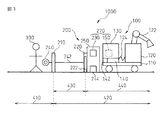
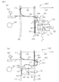
本発明による実施形態について、図を用いて説明する。まず、本発明による安全システム1000(自走ロボット制御システム)について図1および図2を用いて説明する。図1は、本発明による安全システムの概略構成を示す側面図である。図2は本発明による安全システムの概略構成を示す平面図であり、図2(a)は安全システムにおいて自走ロボットがロボット動作非制限領域(第二領域)からロボット動作制限領域(第一領域)まで移動する前の状態を示す図であり、図2(b)は自走ロボットがロボット動作制限領域に移動した後の状態を示す図である。   Embodiments according to the present invention will be described with reference to the drawings. First, a safety system 1000 (self-running robot control system) according to the present invention will be described with reference to FIGS. 1 and 2. FIG. 1 is a side view showing a schematic configuration of a safety system according to the present invention. FIG. 2 is a plan view showing a schematic configuration of a safety system according to the present invention. FIG. 2 (a) is a diagram illustrating a safety system in which a self-running robot moves from a robot motion non-restricted region (second region) to a robot motion restricted region (first region). FIG. 2B is a diagram illustrating a state after the self-running robot has moved to the robot operation restriction region.

安全システム1000は、自走する自走ロボット100と、自走ロボット100と有線接続した場合に、自走ロボット100を強制的に制御可能となるステーション200(指令装置)とから構成されている。   The safety system 1000 includes a self-propelled robot 100 that is self-propelled and a station 200 (command device) that can control the self-propelled robot 100 forcibly when wired to the self-propelled robot 100.

安全システム1000が対象とする区域は、第一の仕切210および第二の仕切220によって区画されている。第一の仕切210は、自走ロボット100が進入することのないロボット非動作領域410と、自走ロボット100が進入して動作する可能性のあるロボット動作可能領域420(作業領域)とを区画している。   The area targeted by the safety system 1000 is partitioned by a first partition 210 and a second partition 220. The first partition 210 divides a robot non-operation area 410 into which the self-running robot 100 does not enter and a robot operable area 420 (work area) in which the self-running robot 100 may enter and operate. is doing.

ロボット動作可能領域420は、さらに第二の仕切220により区画されている。第二の仕切220は、人間300が進入する可能性があり自走ロボット100の動作に制限を加える必要のあるロボット動作制限領域430(第一領域)と、人間300が進入することがなく自走ロボット100の動作を制限しないロボット動作非制限領域440(第二領域)とを区画している。ロボット動作非制限領域440は人間300と自走ロボット100との接触が全くないようにする。   The robot operable area 420 is further partitioned by a second partition 220. The second partition 220 includes a robot operation restriction area 430 (first area) in which there is a possibility that the human 300 may enter and the movement of the self-propelled robot 100 needs to be restricted, and the human 300 does not enter the robot. A robot operation unrestricted region 440 (second region) that does not restrict the operation of the running robot 100 is defined. The robot motion non-restricted area 440 prevents any contact between the human 300 and the self-running robot 100.

第一の仕切210および第二の仕切220は一定の高さを有する緩衝材により構成された柵であり、自走ロボット100は柵を乗り越えて移動することはない。また、第一の仕切210および第二の仕切220は緩衝材により構成されているので、自走ロボット100がぶつかった場合でもその衝撃は緩衝される。第一の仕切210によって自走ロボット100がロボット非動作領域410に進入することはないため、ロボット非動作領域410の内部にいる人間300は常に安全な状態である。第一の仕切210の一部には人間が出入りするための扉212(図2参照)が配置されており、扉212は開けられた場合にフェンス信号(人間が所定の場所に進入した場合に状態が変化する信号)を発信するようになっている。   The first partition 210 and the second partition 220 are fences made of a cushioning material having a certain height, and the self-propelled robot 100 does not move over the fence. Further, since the first partition 210 and the second partition 220 are made of a cushioning material, the impact is buffered even when the self-propelled robot 100 hits. Since the self-running robot 100 does not enter the robot non-operation area 410 due to the first partition 210, the person 300 inside the robot non-operation area 410 is always in a safe state. A part of the first partition 210 is provided with a door 212 (see FIG. 2) for a person to enter and exit. When the door 212 is opened, a fence signal (when a person enters a predetermined place) A signal that changes state) is transmitted.

第二の仕切220には、自走ロボット100がロボット動作制限領域430とロボット動作非制限領域440とを移動する経路224(図2参照)が設けられている。また、経路224には後述するステーション200のステーション制御部250の指示により自動的に開閉可能な自動扉222が設けられている。さらに、自動扉222はステーション制御部250の要求に応じて扉の状態を示す扉状態信号を送信する機能を有する。第二の仕切220に設けられた自動扉222が開くことにより、自走ロボット100は経路224を自走してロボット動作制限領域430およびロボット動作非制限領域440間の往来が可能となっている。すなわち、第二の仕切220は自走ロボット100の移動を選択的に許容する障害部の役割を果たす。   The second partition 220 is provided with a path 224 (see FIG. 2) through which the self-running robot 100 moves between the robot motion restriction region 430 and the robot motion non-restriction region 440. The path 224 is provided with an automatic door 222 that can be automatically opened and closed by an instruction from a station controller 250 of the station 200 described later. Furthermore, the automatic door 222 has a function of transmitting a door state signal indicating a door state in response to a request from the station control unit 250. When the automatic door 222 provided in the second partition 220 is opened, the self-running robot 100 can self-travel along the path 224 and can travel between the robot operation restricted area 430 and the robot action non-restricted area 440. . That is, the second partition 220 serves as an obstacle that selectively allows the movement of the self-running robot 100.

次に、自走ロボット100について説明する。自走ロボット100は、走行部110、作業部120、ロボット制御部130(制御部)、バッテリ140およびロボット側接続手段150(接続機構の一部)を備えている。走行部110は自走ロボット100の自走を実現する装置であり、本実施形態の自走ロボット100の走行部110は無人搬送台車である。自走ロボット100はロボット制御部130が走行部110に動作を指示することにより移動可能となっている。   Next, the self-running robot 100 will be described. The self-running robot 100 includes a traveling unit 110, a working unit 120, a robot control unit 130 (control unit), a battery 140, and a robot side connection unit 150 (part of a connection mechanism). The traveling unit 110 is a device that realizes the self-running of the self-running robot 100, and the traveling unit 110 of the self-running robot 100 according to the present embodiment is an automatic guided vehicle. The self-running robot 100 is movable when the robot control unit 130 instructs the running unit 110 to operate.

作業部120はワークを運搬するアーム122を有するロボットアームである。作業部120は作業用ケーブル124によりロボット制御部130に接続されており、ロボット制御部130からの指示により作業を行う。   The working unit 120 is a robot arm having an arm 122 that carries a workpiece. The working unit 120 is connected to the robot control unit 130 by a working cable 124 and performs work according to an instruction from the robot control unit 130.

ロボット制御部130は走行部110、作業部120および後述するロボット側接続手段150を制御する機器である。すなわち、ロボット制御部130はソフトウェア、プログラムによって走行部110や作業部120を制御する制御回路である。ロボット制御部130はCPU、データメモリおよびインタフェイス等を備えた周知のものでよく、故にその詳細な説明は省略する。ロボット制御部130は、さらに外部(例えばステーション200)より入力された信号を受信して処理する信号処理回路132を備えている。信号処理回路132は外部より受信した信号を処理して、処理した信号をロボット制御部130に送信する。ロボット制御部130は信号処理回路132から受信した信号に基づいて、走行部110や作業部120を制御する。例えば、信号処理回路132がステーション200より安全信号(強制制御指令の一例、停止指令)を受信した場合に安全信号をロボット制御部130に送信して、ロボット制御部130は受信した安全信号に基づいて走行部110や走行部120を強制停止するよう制御する。   The robot control unit 130 is a device that controls the traveling unit 110, the working unit 120, and a robot side connection unit 150 described later. That is, the robot control unit 130 is a control circuit that controls the traveling unit 110 and the working unit 120 by software and programs. The robot control unit 130 may be a well-known one having a CPU, a data memory, an interface, and the like, and thus detailed description thereof is omitted. The robot control unit 130 further includes a signal processing circuit 132 that receives and processes a signal input from the outside (for example, the station 200). The signal processing circuit 132 processes a signal received from the outside and transmits the processed signal to the robot control unit 130. The robot control unit 130 controls the traveling unit 110 and the working unit 120 based on the signal received from the signal processing circuit 132. For example, when the signal processing circuit 132 receives a safety signal (an example of a forced control command, a stop command) from the station 200, the safety signal is transmitted to the robot control unit 130, and the robot control unit 130 is based on the received safety signal. Then, the traveling unit 110 and the traveling unit 120 are controlled to be forcibly stopped.

また、ロボット制御部130は、ステーション200の位置(後述するステーション側接続手段230を含む)とステーション200を起点として自走ロボットが移動した経路とをデータメモリに記憶している。ロボット制御部130がステーション200を起点として移動した経路を逆に進むよう走行部110に指示することにより自走ロボット100をステーション200に近接させることが可能になっている。   In addition, the robot control unit 130 stores the position of the station 200 (including a station side connection unit 230 described later) and the path traveled by the self-running robot from the station 200 as a starting point. The robot control unit 130 can instruct the traveling unit 110 to travel backward on the route traveled from the station 200, thereby allowing the self-running robot 100 to approach the station 200.

自走ロボット100は、バッテリ140とそのバッテリを充電する充電回路142とを備えている。自走ロボット100が有する他の構成要素、移動部110、作業部120およびロボット制御部130は、バッテリ140から電力を供給されることにより動作可能となっている。すなわち、自走ロボット100は、バッテリ140を搭載しているので、ロボット動作可能領域420においては、外部電源と接続することなく自走可能または作業可能になっている。   Self-running robot 100 includes a battery 140 and a charging circuit 142 that charges the battery. Other components included in the self-running robot 100, the moving unit 110, the working unit 120, and the robot control unit 130 are operable by being supplied with electric power from the battery 140. That is, since the self-propelled robot 100 is equipped with the battery 140, the robot operable region 420 can be self-propelled or work without being connected to an external power source.

ロボット側接続手段150は、後述するステーション200のステーション側接続手段230と有線接続可能な機器であり、自走ロボット100とステーション200との有線接続を自動的に確立または自動的に解除する接続機構270の一部である。ロボット側接続手段150は信号処理部132に接続している。ロボット側接続手段150は、自走ロボット100がロボット動作非制限領域440からロボット動作制限領域430まで移動するときに、自動的にステーション側接続手段230と有線接続できるよう構成されている。ロボット側接続手段150の構成およびロボット側接続手段150とステーション側接続手段230とが自動的に有線接続を確立または切り離す手順については後述する。   The robot side connection unit 150 is a device that can be wired to a station side connection unit 230 of the station 200 described later, and a connection mechanism that automatically establishes or automatically releases a wired connection between the self-running robot 100 and the station 200. 270. The robot side connection means 150 is connected to the signal processing unit 132. The robot side connection unit 150 is configured to automatically connect to the station side connection unit 230 by wire when the self-running robot 100 moves from the robot operation non-restriction region 440 to the robot operation restriction region 430. The configuration of the robot side connection unit 150 and the procedure for automatically establishing or disconnecting the wired connection between the robot side connection unit 150 and the station side connection unit 230 will be described later.

次に、安全システム1000のステーション200(指令装置)について説明する。ステーション200は、自走ロボット100と有線接続した場合に自走ロボット100を制御可能となる装置であり、ステーション200は、自走ロボット100のロボット側接続手段150と有線接続するステーション側接続手段230(接続機構270の一部)、安全信号を入力するための安全スイッチ240、ステーション200に入力された信号をモニタし、ステーション200に接続された外部機器を制御するステーション制御部250、安全スイッチ240および第一の仕切210の扉212と接続するケーブル242、自走ロボット100の通過を検知するロボット通過検知センサ244、電力を供給する給電装置260とから構成されている。本実施形態において、ステーション200のステーション制御部250とステーション側接続手段230とはロボット動作非制限領域440内であって、自走ロボット100がロボット動作制限領域430に移動する際に必ず経由する経路224の近傍に配置されている。   Next, the station 200 (command device) of the safety system 1000 will be described. The station 200 is a device that can control the self-propelled robot 100 when connected to the self-propelled robot 100 by wire. The station 200 is a station-side connection means 230 that is wired to the robot-side connection means 150 of the self-propelled robot 100. (Part of the connection mechanism 270), a safety switch 240 for inputting a safety signal, a station controller 250 for monitoring a signal input to the station 200 and controlling an external device connected to the station 200, a safety switch 240 And a cable 242 connected to the door 212 of the first partition 210, a robot passage detection sensor 244 that detects passage of the self-running robot 100, and a power feeding device 260 that supplies electric power. In the present embodiment, the station control unit 250 and the station side connection means 230 of the station 200 are in the robot operation non-restricted area 440, and a route through which the self-running robot 100 always moves when moving to the robot operation restricted area 430. 224 is arranged in the vicinity.

ステーション側接続手段230は、自走ロボット100がロボット動作制限領域430内に移動する場合に、自走ロボット100のロボット側接続手段150と有線接続する機器であり、接続機構270の一部である。ステーション側接続手段230は自走ロボット100のロボット側接続手段150と同じ高さの位置に配置されている。自走ロボット100がステーション側接続手段230に近接することにより接続可能となっている。接続するための構成および接続の手順は後述する。ステーション側接続手段230はステーション制御部250と接続されており、ステーション制御部250は、ロボット側接続手段150およびステーション側接続手段230が有線接続した場合、ステーション側接続手段230を経由して自走ロボット100を制御することが可能となる。   The station-side connection unit 230 is a device that is wired to the robot-side connection unit 150 of the self-running robot 100 when the self-running robot 100 moves into the robot operation restriction region 430 and is a part of the connection mechanism 270. . The station side connection means 230 is disposed at the same height as the robot side connection means 150 of the self-running robot 100. The self-running robot 100 can be connected by being close to the station side connecting means 230. A configuration for connection and a connection procedure will be described later. The station side connection unit 230 is connected to the station control unit 250. When the robot side connection unit 150 and the station side connection unit 230 are connected by wire, the station control unit 250 is self-propelled via the station side connection unit 230. The robot 100 can be controlled.

安全スイッチ240は、ステーション200が安全信号を自走ロボット100に送信するためのトリガであって、本実施形態では人間300が安全に行動できるロボット非動作領域410に配置されている。安全スイッチ240とステーション制御部250とは信号伝達ケーブル242により有線接続されており、ステーション制御部250は安全スイッチ230が押し下げられたか否かを常にモニタしている。ステーション制御部250は安全スイッチ230が押し下げられたと判定した場合に、安全信号を自走ロボット100に送信する。すなわち、人間300が安全スイッチを押し下げることにより、ステーション制御部250は自走ロボット100に安全信号を送信して自走ロボット100は強制的に停止する。安全スイッチ230と自走ロボット100とは物理的に離れているので、自走ロボット100とステーション200とが有線接続されている場合、人間300は安全な状態で自走ロボット100を停止できる。   The safety switch 240 is a trigger for the station 200 to transmit a safety signal to the self-running robot 100. In the present embodiment, the safety switch 240 is disposed in the robot non-operation area 410 where the human 300 can act safely. The safety switch 240 and the station control unit 250 are connected by a signal transmission cable 242, and the station control unit 250 always monitors whether the safety switch 230 is pushed down. When the station control unit 250 determines that the safety switch 230 has been pressed, the station control unit 250 transmits a safety signal to the self-running robot 100. That is, when the human 300 depresses the safety switch, the station control unit 250 transmits a safety signal to the self-running robot 100 and the self-running robot 100 is forcibly stopped. Since the safety switch 230 and the self-running robot 100 are physically separated, when the self-running robot 100 and the station 200 are connected by wire, the human 300 can stop the self-running robot 100 in a safe state.

また、前述したように第一の仕切210の扉212はフェンス信号が出力可能であり、扉212とステーション制御部250とは信号伝達ケーブル242により有線接続されている。扉212は、扉が開けられたことを検知してフェンス信号を、信号伝達ケーブル242を経由してステーション制御部250に送信する。ステーション制御部250はフェンス信号が入力されたか否かをモニタしており、ステーション制御部250は、第一の仕切210から、ロボット動作制限領域430に人間が進入したかもしれないことを示すフェンス信号が入力されたと判定した場合に自走ロボット100に対して安全信号を送信する。そのため、人間300が不用意にロボット動作制限領域430に進入した場合においても、ステーション200と有線接続している自走ロボット100を停止させることができる。   As described above, the door 212 of the first partition 210 can output a fence signal, and the door 212 and the station control unit 250 are connected to each other by a signal transmission cable 242. The door 212 detects that the door has been opened and transmits a fence signal to the station control unit 250 via the signal transmission cable 242. The station control unit 250 monitors whether or not a fence signal is input, and the station control unit 250 indicates that a human may have entered the robot operation restriction area 430 from the first partition 210. When it is determined that is input, a safety signal is transmitted to the self-running robot 100. Therefore, even when the human 300 carelessly enters the robot operation restriction area 430, the self-running robot 100 connected to the station 200 by wire can be stopped.

ステーション制御部250は、前述のように、ケーブルにより有線接続された安全スイッチ240やセンサなどから入力される信号をモニタして、ステーション制御部250と接続している機器を制御する機器である。ステーション制御部250は制御回路であり、CPU、データメモリおよびインタフェイス等を備えた周知のものでよく、故にその詳細な説明は省略する。ステーション制御部250は、前述のように信号伝達ケーブル242により接続された安全スイッチ240や第一の仕切210の扉212からの信号をモニタすることにより、安全信号を自走ロボット100に送信する、すなわち自走ロボット100を強制的に停止するよう指示する機能を有する。また、ステーション制御部250は、ステーション側接続手段230とロボット側接続手段150とが正常に接続され所定の信号を受信したか否かを判定する機能も有する。ステーション制御部250が接続手段の正常接続を判定する方法については後述する。   As described above, the station control unit 250 is a device that controls a device connected to the station control unit 250 by monitoring a signal input from a safety switch 240 or a sensor wired by a cable. The station control unit 250 is a control circuit, and may be a well-known one including a CPU, a data memory, an interface, and the like, and thus detailed description thereof is omitted. The station control unit 250 transmits a safety signal to the self-running robot 100 by monitoring signals from the safety switch 240 and the door 212 of the first partition 210 connected by the signal transmission cable 242 as described above. That is, it has a function of instructing to stop the self-running robot 100 forcibly. The station control unit 250 also has a function of determining whether or not the station side connection unit 230 and the robot side connection unit 150 are normally connected and receive a predetermined signal. A method by which the station control unit 250 determines the normal connection of the connection means will be described later.

ステーション制御部250は、さらに、第二の仕切220に設けられた自動扉222とロボット通過検知センサ244とに接続している。ステーション制御部250は自動扉222から扉の開閉状態を示す扉状態信号を受信する。また、自動扉222の開閉を指示する。ロボット通過検知センサ244は、自走ロボット100の通過を検知するセンサであり、自走ロボット100の通過を示す通過検知信号をステーション制御部250に送信する。ステーション制御部250はロボット通過検知センサ244と接続しているので、ステーション制御部250は通過検知信号を受信した場合、その通過検知信号の内容に応じて自動扉222に対して開閉を指示することが可能となっている。ロボット通過検知センサ244は、例えば、視覚センサを用いて自走ロボット100を撮像した画像を入手して自走ロボット100通過を検知してもよい。また、ロボット通過検知センサ244は、ライトカーテンを経路224に設けて自走ロボット100が通過することによりライトカーテンが遮断されたことを計測することにより、自走ロボット100が通過したことを検知してもよい。ロボット通過検知センサ244は、経路224の床面に複数のボタンを設けボタン上を自走ロボット100が通過してボタンを自重により押下げることにより、自走ロボット100が経路224を通過してロボット動作非制限領域440に移動したことを検知してもよい。   The station control unit 250 is further connected to an automatic door 222 and a robot passage detection sensor 244 provided in the second partition 220. The station control unit 250 receives a door state signal indicating the open / closed state of the door from the automatic door 222. In addition, an instruction to open and close the automatic door 222 is given. The robot passage detection sensor 244 is a sensor that detects the passage of the self-running robot 100, and transmits a passage detection signal indicating the passage of the self-running robot 100 to the station control unit 250. Since the station control unit 250 is connected to the robot passage detection sensor 244, when the station control unit 250 receives the passage detection signal, the station control unit 250 instructs the automatic door 222 to open and close according to the content of the passage detection signal. Is possible. For example, the robot passage detection sensor 244 may detect the passage of the self-running robot 100 by obtaining an image obtained by imaging the self-running robot 100 using a visual sensor. Further, the robot passage detection sensor 244 detects that the self-propelled robot 100 has passed by providing a light curtain on the path 224 and measuring that the light curtain has been blocked by the passage of the self-propelled robot 100. May be. The robot passage detection sensor 244 is provided with a plurality of buttons on the floor surface of the path 224, and the self-running robot 100 passes over the buttons and pushes the button down by its own weight. You may detect having moved to the operation non-restricted area 440.

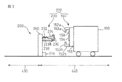
次に、ステーション200のステーション側接続手段230と自走ロボット100のロボット側接続手段150との接続する構成(接続機構270)について図3を用いて説明する。図3はステーション200のステーション側接続手段230と自走ロボット100のロボット側接続手段150とが有線接続するための構成を示す図である。図3は理解を容易にするために、それぞれの接続手段を誇張し拡大して示している。また有線接続に関係しない部分は省略した。   Next, a configuration (connection mechanism 270) for connecting the station side connection means 230 of the station 200 and the robot side connection means 150 of the self-running robot 100 will be described with reference to FIG. FIG. 3 is a diagram showing a configuration for making a wired connection between the station-side connection means 230 of the station 200 and the robot-side connection means 150 of the self-running robot 100. FIG. 3 exaggerates and enlarges each connection means for easy understanding. Parts not related to wired connection are omitted.

まず、ステーション側接続手段230について説明する。ステーション側接続手段230は、ステーション制御部250からの信号を伝達する接続ケーブル232、ロボット側接続手段150と機械的に嵌合するステーション側嵌合部234、ロボット側接続手段150と電気的に接続するステーション側コネクタ236(第一コネクタ)およびステーション側嵌合部234およびステーション側コネクタ236を支持する支持体239を有している。   First, the station side connection means 230 will be described. The station side connection means 230 is electrically connected to the connection cable 232 that transmits a signal from the station control unit 250, the station side fitting part 234 that mechanically fits with the robot side connection means 150, and the robot side connection means 150. The station side connector 236 (first connector) and the station side fitting portion 234 and the support body 239 for supporting the station side connector 236 are provided.

接続ケーブル232の一方の端部はステーション制御部250に接続しており、他方の端部はステーション側嵌合部234に接続している。接続ケーブル232は、バネやコイルように巻線形となっており伸縮自在となっている。そのため、有線接続を確立する際のステーション側嵌合部234の位置は固定されているが、有線接続後はステーション側嵌合部234とステーション制御部250との距離は可変である。また、ステーション側嵌合部234の下側には支持体239が設けられており、支持体239はステーション側嵌合部234が所定の高さに配置されるよう、ステーション側嵌合部234を支持している。   One end of the connection cable 232 is connected to the station control unit 250, and the other end is connected to the station side fitting unit 234. The connection cable 232 has a winding shape such as a spring or a coil and can be expanded and contracted. For this reason, the position of the station side fitting portion 234 when the wired connection is established is fixed, but the distance between the station side fitting portion 234 and the station control portion 250 is variable after the wired connection. Further, a support body 239 is provided below the station side fitting portion 234, and the support body 239 has the station side fitting portion 234 arranged so that the station side fitting portion 234 is arranged at a predetermined height. I support it.

ステーション側嵌合部234は、断面がT字形の部材であり、端部には上下に突出した突出部238を有している。ステーション側嵌合部234はロボット側接続手段150と嵌合して突出部238が引掛ることにより、ステーション側接続手段230とロボット側接続手段150とが容易に切り離されることがなくなる。ステーション側嵌合部234の端部には、容易に繰り返し脱着することが可能なコネクタであるステーション側コネクタ236(第一コネクタ)が配置されており、ステーション側嵌合部234がロボット側接続手段150と嵌合した場合、自走ロボット100と電気的に接続するように構成されている。   The station side fitting portion 234 is a member having a T-shaped cross section, and has a protruding portion 238 protruding upward and downward at an end portion. The station-side fitting unit 234 is fitted to the robot-side connecting unit 150 and the protrusion 238 is hooked, so that the station-side connecting unit 230 and the robot-side connecting unit 150 are not easily separated. A station-side connector 236 (first connector) that is a connector that can be easily and repeatedly attached and detached is disposed at the end of the station-side fitting portion 234, and the station-side fitting portion 234 is a robot-side connecting means. When it is fitted to 150, it is configured to be electrically connected to the self-running robot 100.

次に、ロボット側接続手段150について説明する。ロボット側接続手段150は、ステーション側接続手段230と機械的に嵌合するロボット側嵌合部152、ステーション側接続手段230と電気的に接続するロボット側コネクタ154、ロボット制御部130の指示によりロボット側嵌合部152を動かす駆動部156およびステーション側コネクタ236の位置を撮像する視覚センサ158を有している。ロボット側嵌合部152は、断面がL字形の部材であり、ロボット側嵌合部152の端部にはステーション側嵌合部234の突出部238に引掛ける引掛部153を有している。ロボット側嵌合部152は二つの部材からなり、ロボット側接続手段150の上下に配置されている。二つの部材は上側を上側ロボット側嵌合部152a、下側を下側ロボット側嵌合部152bとし、それぞれの引掛部153a、153bが対向するよう配置されている。ロボット側嵌合部152は、ロボット制御部130が駆動部156に指示することにより上下に動作可能となっており、ステーション側嵌合部234を挟み込むことができる。また、自走ロボット100は、ロボット側嵌合部152とステーション側嵌合部234とが嵌合した場合、ステーション200に嵌合が完了したことを示す嵌合状態信号を発信できる。   Next, the robot side connection means 150 will be described. The robot-side connecting means 150 includes a robot-side fitting section 152 that mechanically engages with the station-side connecting means 230, a robot-side connector 154 that electrically connects with the station-side connecting means 230, and a robot according to instructions from the robot control section 130. A visual sensor 158 that images the position of the drive unit 156 that moves the side fitting unit 152 and the station-side connector 236 is provided. The robot-side fitting portion 152 is a member having an L-shaped cross section, and has a hooking portion 153 that hooks on the protruding portion 238 of the station-side fitting portion 234 at the end of the robot-side fitting portion 152. The robot-side fitting portion 152 is composed of two members and is disposed above and below the robot-side connecting means 150. The two members have an upper robot side fitting portion 152a on the upper side and a lower robot side fitting portion 152b on the lower side, and the hooking portions 153a and 153b are arranged to face each other. The robot side fitting unit 152 can be moved up and down by the robot control unit 130 instructing the driving unit 156 and can sandwich the station side fitting unit 234. Further, when the robot-side fitting unit 152 and the station-side fitting unit 234 are fitted, the self-running robot 100 can transmit a fitting state signal indicating that the fitting is completed to the station 200.

ロボット側コネクタ154は、ステーション側コネクタ236と対向する位置に配置されており、自走ロボット100がステーション200に向かって近づくことにより、ステーション側コネクタ236と接続して通電可能な状態、すなわちロボット側接続手段150とステーション側接続手段230とが有線接続された状態となる。   The robot-side connector 154 is disposed at a position facing the station-side connector 236. When the self-running robot 100 approaches the station 200, the robot-side connector 154 can be connected to the station-side connector 236 and energized, that is, the robot side. The connection means 150 and the station side connection means 230 are connected in a wired manner.

ロボット側接続手段150には、ステーション側コネクタ236の位置を撮像する視覚センサ158が設けられている。自走ロボット100は、ステーション側接続手段230に近接した場合、視覚センサ158から入手した画像データを基にして正確なステーション側コネクタ236の位置を求め、その位置データに従って自走ロボット100はステーション側接続手段230に向けて自走する。自走ロボット100が視覚センサ158を用いて正確にステーション側接続手段230に向かって自走することによりロボット側コネクタ154とステーション側コネクタ236が接続することができる。   The robot side connection means 150 is provided with a visual sensor 158 that images the position of the station side connector 236. When the self-propelled robot 100 comes close to the station-side connecting means 230, the self-propelled robot 100 obtains an accurate position of the station-side connector 236 based on the image data obtained from the visual sensor 158. Self-propelled toward the connection means 230. When the self-running robot 100 accurately self-propels toward the station side connection means 230 using the visual sensor 158, the robot side connector 154 and the station side connector 236 can be connected.

それぞれのコネクタが接続した後にロボット側嵌合部152が動作し嵌合すれば、それぞれのコネクタは外れることはなく、ステーション制御部250からの信号を確実に自走ロボット100に送信することが可能となる。接続ケーブル232は自走ロボット100の動きに合わせて伸張できるので、嵌合後は、自走ロボット100がロボット動作制限領域430に移動した場合においても有線接続している状態を保つことができる。すなわち、ステーション200は、自走ロボット100がロボット動作制限領域430内において移動または作業を行う場合でも、有線接続により自走ロボット100を強制的に制御することが可能となる。   If the robot-side fitting section 152 operates and engages after the respective connectors are connected, the respective connectors will not be disconnected, and the signal from the station control section 250 can be reliably transmitted to the self-running robot 100. It becomes. Since the connection cable 232 can be extended in accordance with the movement of the self-running robot 100, the wire connection state can be maintained even after the self-running robot 100 moves to the robot operation restriction region 430 after the fitting. That is, the station 200 can forcibly control the self-running robot 100 by wired connection even when the self-running robot 100 moves or works within the robot operation restriction area 430.

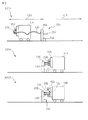
次に、図4および図5を用いて、本発明による自走ロボット100がロボット動作制限領域430とロボット動作非制限領域440との間を移動する際に、自走ロボット100とステーション200とが自動的に有線接続を確立、またその有線接続を切り離す手順について説明する。   4 and 5, when the self-running robot 100 according to the present invention moves between the robot operation restricted area 430 and the robot action non-restricted area 440, the self-running robot 100 and the station 200 are A procedure for automatically establishing a wired connection and disconnecting the wired connection will be described.

まず、図4を用いて自走ロボット100がロボット動作制御領域430に進入する際の手順、とくにステーション制御部250が正常に接続されたか否かを判定する方法について説明する。図4は自走ロボット100がロボット動作制御領域430に進入する際に、自走ロボット100がステーション200と有線接続を確立する手順、ステップS101からステップS104を示す図である。   First, a procedure when the self-running robot 100 enters the robot motion control region 430, particularly a method for determining whether or not the station control unit 250 is normally connected, will be described with reference to FIG. FIG. 4 is a diagram showing a procedure for establishing a wired connection with the station 200 when the self-running robot 100 enters the robot motion control region 430, step S101 to step S104.

ステップS101は、自走ロボット100がロボット動作非制限領域440に存在し、自走ロボット100とステーション200とは有線接続していない状態を示している。図に示すように、ロボット側接続手段150のロボット側嵌合部152は開けられた状態となっており、ロボット側コネクタ154は外部に露出されている。一方、ステーション200のステーション制御部250は、安全スイッチ240と第一の仕切210とからの安全信号、自動扉222からの扉状態信号およびステーション側接続手段230からの信号をモニタしている状態である。また、自走ロボット100がロボット動作制限領域430に進入するための自動扉222は閉じている状態である。   Step S101 shows a state in which the self-running robot 100 exists in the robot operation unrestricted area 440 and the self-running robot 100 and the station 200 are not connected by wire. As shown in the figure, the robot-side fitting portion 152 of the robot-side connecting means 150 is in an opened state, and the robot-side connector 154 is exposed to the outside. On the other hand, the station control unit 250 of the station 200 monitors the safety signal from the safety switch 240 and the first partition 210, the door state signal from the automatic door 222, and the signal from the station side connection means 230. is there. Moreover, the automatic door 222 for the self-running robot 100 to enter the robot operation restriction area 430 is in a closed state.

次に、ステップS102について説明する。自走ロボット100は、ロボット動作制限領域440からロボット動作制限領域430へ移動するという動作プログラムに従い、ステーション200に向かって自走し、ステーション200に近接する。そして自走ロボット100は視覚センサ158を利用してステーション側コネクタ236とロボット側コネクタ154とが接続する位置へ移動する。なお、本実施形態では自走ロボット100は前述したように、ロボット制御部130が記憶するステーション200の位置情報に基づいて近接している。   Next, step S102 will be described. The self-running robot 100 follows the operation program of moving from the robot operation restriction region 440 to the robot operation restriction region 430 and moves toward the station 200 and approaches the station 200. The self-running robot 100 moves to a position where the station side connector 236 and the robot side connector 154 are connected using the visual sensor 158. In this embodiment, as described above, the self-running robot 100 is close based on the position information of the station 200 stored in the robot control unit 130.

ステップS103について説明する。自走ロボット100は、視覚センサ158を用いてステーション側コネクタ236の位置を確認しつつ移動し、ロボット側コネクタ154とステーション側コネクタ236とを接続させる。接続した後、自走ロボット100は駆動部156を用いてロボット側嵌合部152を移動させ、ステーション側嵌合部234との嵌合を完了させる。嵌合が完了した時点で、ステーション側コネクタ236から接続ケーブル232を経由して嵌合が完了したことを示す嵌合状態信号がステーション制御部250に送信される。ステーション制御部250は嵌合状態信号を受信した場合、ステーション制御部250がモニタしている安全信号を受信していない状態(安全スイッチ240が押し下げられておらず、第一の仕切210の扉212がフェンス信号をステーション制御部250に入力していない状態)であることを確認する。ステーション制御部250はロボット側嵌合部152とステーション側嵌合部234が嵌合したこと、および安全スイッチ240から安全信号を受信していない状態であることを確認することにより、自走ロボット100とステーション200とが正常に有線接続が確立されたと判定して自動扉222に開けることを指示する。すなわち、ステーション制御部250に安全信号が入力されている場合は、安全信号により自走ロボットが強制的に停止されているのみならず、ステーション制御部250により自動扉222を開けられることはない。   Step S103 will be described. The self-running robot 100 moves while confirming the position of the station-side connector 236 using the visual sensor 158, and connects the robot-side connector 154 and the station-side connector 236. After the connection, the self-running robot 100 moves the robot-side fitting unit 152 using the driving unit 156 to complete the fitting with the station-side fitting unit 234. When the fitting is completed, a fitting state signal indicating that the fitting is completed is transmitted from the station side connector 236 via the connection cable 232 to the station control unit 250. When the station control unit 250 receives the fitting state signal, the station control unit 250 does not receive the safety signal monitored by the station control unit 250 (the safety switch 240 is not pushed down and the door 212 of the first partition 210 is not pressed). Is in a state where no fence signal is input to the station controller 250. The station control unit 250 confirms that the robot-side fitting unit 152 and the station-side fitting unit 234 are fitted, and that the safety signal is not received from the safety switch 240, so that the self-running robot 100 And the station 200 determine that the wired connection has been normally established and instruct to open the automatic door 222. That is, when a safety signal is input to the station control unit 250, not only the self-running robot is forcibly stopped by the safety signal, but the automatic door 222 is not opened by the station control unit 250.

ステップS104について説明する。自走ロボット100がステーション200と有線接続した後、ロボット制御部130は接続ケーブル232を介してステーション制御部250からの安全信号をモニタすることが可能となる。また、ステーション制御部250から扉状態信号を受信することにより、自動扉222の開閉状態を確認可能となる。ロボット制御部130は、ロボット側接続手段150とステーション側接続手段230との嵌合が完了していること、ステーション200から安全信号が入力されていない状態であること、自動扉222が開いていることを確認する。ロボット制御部130の確認後、自走ロボット100は走行部120により自走を開始し、ロボット動作制限領域430に進入する。図4のステップ104は自走ロボット100が有線接続によりステーション200からの安全信号をモニタしつつ、ロボット動作制限領域430の内部に進入している状態を示している。   Step S104 will be described. After the self-running robot 100 is connected to the station 200 by wire, the robot control unit 130 can monitor the safety signal from the station control unit 250 via the connection cable 232. In addition, by receiving a door state signal from the station control unit 250, it is possible to check the open / closed state of the automatic door 222. The robot control unit 130 indicates that the fitting between the robot side connection unit 150 and the station side connection unit 230 is completed, that no safety signal is input from the station 200, and the automatic door 222 is open. Make sure. After confirmation by the robot control unit 130, the self-running robot 100 starts self-running by the running unit 120 and enters the robot operation restriction area 430. Step 104 of FIG. 4 shows a state in which the self-running robot 100 is entering the robot operation restriction area 430 while monitoring a safety signal from the station 200 by wired connection.

次に、図5を用いて自走ロボット100がロボット動作制限領域430からロボット動作非制限領域440まで移動する流れについて説明する。図5は自走ロボット100がロボット制限領域430からロボット非制限領域440にまで移動する際に有線接続を切り離す手順であるステップS201からステップS203を示す図である。   Next, a flow in which the self-running robot 100 moves from the robot motion restriction region 430 to the robot motion non-restriction region 440 will be described with reference to FIG. FIG. 5 is a diagram showing steps S201 to S203 which are procedures for disconnecting the wired connection when the self-running robot 100 moves from the robot restricted area 430 to the robot unrestricted area 440.

ステップS201は、自走ロボット100がロボット動作制限領域430内に存在する状態であり、自走ロボット100とステーション200とが有線接続されている状態を示している。自走ロボット100がロボット動作制限領域430内に存在する場合、自動扉222は開いているものとする。   Step S201 shows a state where the self-running robot 100 exists in the robot operation restriction area 430 and the self-running robot 100 and the station 200 are connected by wire. When the self-running robot 100 exists in the robot operation restriction area 430, the automatic door 222 is assumed to be open.

次に、自動扉222を閉めるタイミングと、自走ロボット100とステーション200と切り離す動作について説明する。ステップS202は、自走ロボット100が経路224を通過し、自走ロボット100がロボット動作非制限領域440に移動した状態を示している。ロボット通過検知センサ244は、自走ロボット100がロボット動作制限領域430からロボット動作非制限領域440に通過したことを検知し、自走ロボット100がロボット動作非制限領域440へ通過したことを示す通過検知信号を送信する。ステーション制御部250はその通過検知信号を受信し、自走ロボット100がロボット動作非制限領域440へ移動したと判定し、自動扉222を閉じる指示をする。自動扉222は閉じた後、ステーション制御部250に扉が閉じている状態を示す扉状態信号を送信する。自走ロボット100のロボット制御部130はステーション制御部250を経由して扉状態信号を受信し、自動扉222が閉じたことを確認する。自走ロボット100のロボット制御部130は自動扉222が閉じたことを確認した後、ロボット側接続手段150のロボット側嵌合部152を動作させステーション側嵌合部234との嵌合を解除する。   Next, the timing for closing the automatic door 222 and the operation for separating the self-running robot 100 from the station 200 will be described. Step S202 shows a state where the self-running robot 100 has passed the path 224 and the self-running robot 100 has moved to the robot motion non-restricted region 440. The robot passage detection sensor 244 detects that the self-running robot 100 has passed from the robot motion restriction region 430 to the robot motion non-restriction region 440, and indicates that the self-running robot 100 has passed the robot motion non-restriction region 440. Send a detection signal. The station control unit 250 receives the passage detection signal, determines that the self-running robot 100 has moved to the robot motion non-restricted region 440, and gives an instruction to close the automatic door 222. After the automatic door 222 is closed, the door control signal is transmitted to the station controller 250 indicating that the door is closed. The robot controller 130 of the self-running robot 100 receives the door state signal via the station controller 250 and confirms that the automatic door 222 is closed. After confirming that the automatic door 222 is closed, the robot control unit 130 of the self-running robot 100 operates the robot side fitting unit 152 of the robot side connecting means 150 to release the fitting with the station side fitting unit 234. .

ステップS203にて、自走ロボット100のロボット制御部130は嵌合が解除されたことを確認したのち、自走してステーション200から離れる方向に移動して、ロボット側コネクタ154とステーション側コネクタ236との接続を切り離す。切り離しに先立ちステーションコネクタ236やステーション側嵌合部234は支持体239により所定の位置に固定的に配置された状態となっている。有線接続を切り離した後、自走ロボット100はロボット動作非制限領域440において自動的に走行し作業を行う。   In step S203, the robot control unit 130 of the self-running robot 100 confirms that the fitting has been released, and then moves in the direction of self-run and away from the station 200, and the robot-side connector 154 and the station-side connector 236. Disconnect the connection. Prior to disconnection, the station connector 236 and the station side fitting portion 234 are fixedly arranged at predetermined positions by the support body 239. After disconnecting the wired connection, the self-running robot 100 automatically runs and performs work in the robot motion non-restricted area 440.

以上、図4および図5を用いて本発明による自走ロボット100がロボット動作制限領域430とロボット動作非制限領域440との間を移動する際に、自走ロボット100とステーション200とが自動的に有線接続を確立、またその有線接続を切り離す手順について説明した。上述のように自走ロボット100はロボット動作制限領域430に移動する際、ステーション200と自動的に有線接続を確立する。そのため、人間300は、ロボット制限領域430に移動した自走ロボット100を、自走ロボット100から離れた場所にある安全スイッチ240を用いて非常停止させることが可能となり、人間300の安全を保つことができる。一方、自走ロボット100は人間300と接触することがないロボット動作非制限領域440内においては、ステーション200と有線接続していないので、移動範囲を限定されることなく移動および作業が可能となる。   As described above, when the self-running robot 100 according to the present invention moves between the robot operation restricted area 430 and the robot action non-restricted area 440, the self-running robot 100 and the station 200 are automatically used. Explained the procedure for establishing a wired connection and disconnecting the wired connection. As described above, the self-running robot 100 automatically establishes a wired connection with the station 200 when moving to the robot operation restriction area 430. Therefore, the human 300 can emergency stop the self-running robot 100 that has moved to the robot restricted area 430 by using the safety switch 240 located away from the self-running robot 100, and keep the human 300 safe. Can do. On the other hand, in the robot operation non-restricted area 440 where the self-running robot 100 does not come into contact with the human 300, the mobile robot 100 is not wired with the station 200, so that it can move and work without limiting the movement range. .

本実施形態では、自走ロボット100とステーション200とが有線接続されることにより安全信号を送受信する安全システム1000について述べた。しかしながら、有線接続されることにより送受信される信号は安全信号に限られず、自走ロボット100の移動や作業を制御する信号であっても構わない。また、有線接続により送受信される信号は、人間300が自走ロボット100を遠隔地から操作する信号や自走ロボット100を教示するための信号であってもよい。   In the present embodiment, the safety system 1000 that transmits and receives a safety signal by connecting the self-propelled robot 100 and the station 200 by wire is described. However, the signal transmitted / received by the wired connection is not limited to the safety signal, and may be a signal for controlling the movement and work of the self-running robot 100. The signal transmitted / received by wired connection may be a signal for the human 300 to operate the self-running robot 100 from a remote place or a signal for teaching the self-running robot 100.

接続される接続ケーブル232は、電力を送る電力線であっても構わない。接続ケーブル232が電力線である場合は、ステーション200と自走ロボット100とが有線接続されている間、充電回路142によってステーション200の給電装置260からの電力をバッテリ140に充電可能となる。また、ステーション200と自走ロボット100とが接続されている間は、自走ロボット100はバッテリ140の電力を利用せず、ステーション200の給電装置260から送られる電力を利用して動作してもよい。ステーション200から送られる信号を送る接続ケーブル232と電力を送る電力線と並列して設けることにより、安全信号をモニタしつつバッテリ140を充電するようにしてもよい。有線接続されている間、バッテリ140を充電することにより、有線接続されていないとき(すなわち、ロボット動作非制限領域440に自走ロボットが存在するとき)の自走ロボット100の動作可能時間を延長することができる。   The connection cable 232 to be connected may be a power line that transmits power. When the connection cable 232 is a power line, the battery 140 can be charged with power from the power supply device 260 of the station 200 by the charging circuit 142 while the station 200 and the self-running robot 100 are connected by wire. Further, while the station 200 and the self-running robot 100 are connected, the self-running robot 100 does not use the power of the battery 140, and may operate using the power sent from the power supply device 260 of the station 200. Good. The battery 140 may be charged while monitoring a safety signal by providing a connection cable 232 for sending a signal sent from the station 200 and a power line for sending power. By charging the battery 140 while being connected by wire, the operable time of the self-running robot 100 when the wire connection is not established (that is, when a self-running robot exists in the robot operation unrestricted region 440) is extended. can do.

当該技術分野における当業者にとって明らかであるように、上記説明は、本発明がどのように実施されるかを示した実施例としてのみ解釈されるべきである。また、本発明は、主旨を逸脱しない範囲において当業者の知識に基づき種々なる改良、修正、変更を加えた態様により実施できるものである。例えば、本実施形態においては第一の仕切210および第二の仕切220を、一定の高さを有する緩衝材を用いて構成している。しかしながら、自立ロボット100の進入を妨げるものであれば、車輪止めや頑丈な塀により構成されていても構わない。   As will be apparent to those skilled in the art, the above description should only be construed as an example showing how the invention may be implemented. In addition, the present invention can be carried out in a mode in which various improvements, modifications, and changes are added based on the knowledge of those skilled in the art without departing from the spirit of the present invention. For example, in the present embodiment, the first partition 210 and the second partition 220 are configured using a cushioning material having a certain height. However, as long as it prevents the autonomous robot 100 from entering, it may be constituted by a wheel stopper or a sturdy rod.

また、自走ロボット100とステーション200が有線接続する際、ロボット側接続手段150のロボット側嵌合部152が駆動部156により移動することにより、ステーション側接続手段230のステーション側嵌合部234と嵌合するよう構成されていたが、逆の構成でも構わない。すなわち、ステーション側嵌合部234が挟み込む形状であり(L字形)駆動部を有し、ロボット側嵌合部152が挟み込まれる形状(T字形)とすることによりステーション側嵌合部234がロボット側嵌合部152を挟み込むことにより嵌合して、有線接続を確立しても構わない。また、伸縮可能な接続ケーブル232は自走ロボット100に設けられてもよい。   In addition, when the self-running robot 100 and the station 200 are connected by wire, the robot-side fitting unit 152 of the robot-side connecting unit 150 is moved by the driving unit 156, so that the station-side fitting unit 234 of the station-side connecting unit 230 Although it was comprised so that it might fit, an opposite structure may be sufficient. That is, the station-side fitting portion 234 has a shape that sandwiches (L-shaped) driving unit, and the robot-side fitting portion 152 has a shape that is sandwiched (T-shaped). It is also possible to establish a wired connection by interposing the fitting portion 152 therebetween. The extendable connection cable 232 may be provided in the self-running robot 100.

また、自走ロボット100の信号処理回路132は、外部より安全信号を受信した際に、ロボット制御部130を介さず直接安全信号を走行部110や作業部120に送信してもよい。その場合、走行部110または作業部120は、信号処理回路132から受信した安全信号により停止可能、例えば、バッテリ140から切り離すよう構成しておく。ロボット制御部130を介さないため、処理の遅延により非常停止が遅れることを防ぐ効果がある。   Further, the signal processing circuit 132 of the self-running robot 100 may directly transmit the safety signal to the traveling unit 110 or the working unit 120 without passing through the robot control unit 130 when receiving the safety signal from the outside. In that case, the traveling unit 110 or the working unit 120 can be stopped by a safety signal received from the signal processing circuit 132, for example, separated from the battery 140. Since the robot control unit 130 is not used, there is an effect of preventing the emergency stop from being delayed due to processing delay.

本実施形態においては、自走ロボット100の走行部110は車輪により移動する無人搬送台車であるが、走行部110は例えば多足型の歩行ロボットであっても構わない。自走ロボット100の作業領域は必ずしも平坦な床であるとは限らず、例えば危険な崖である場合がある。そのため、作業領域の状況にあわせて具体的な走行部110は変更可能となっている。   In this embodiment, the traveling unit 110 of the self-running robot 100 is an automatic guided vehicle that moves by wheels, but the traveling unit 110 may be a multi-legged walking robot, for example. The work area of the self-running robot 100 is not necessarily a flat floor, and may be a dangerous cliff, for example. Therefore, the specific traveling unit 110 can be changed according to the situation of the work area.

また、安全スイッチ230は、安全信号を発信するトリガであるため、人が通過したことを検知する赤外線センサまたは人感センサであってもよい。   Moreover, since the safety switch 230 is a trigger for transmitting a safety signal, it may be an infrared sensor or a human sensor that detects that a person has passed.

本実施形態のステーション200は、自走ロボット100とステーション200との有線接続を切り離す際、自走ロボット100がロボット動作非制限領域440に移動したか否かを、ロボット通過検知センサ242からの信号を基に判定していた。しかしながら、自走ロボット100自身が自己の位置を随時記録している場合、自走ロボット100がステーション制御部250に位置を示す信号を入力することにより、ステーション制御部250がその信号に基づいて自走ロボットがロボット動作非制限領域440に移動したか否かを判定しても構わない。   When the station 200 of this embodiment disconnects the wired connection between the self-running robot 100 and the station 200, a signal from the robot passage detection sensor 242 indicates whether or not the self-running robot 100 has moved to the robot motion non-restricted region 440. Judgment based on. However, when the self-running robot 100 records its own position at any time, the self-running robot 100 inputs a signal indicating the position to the station control unit 250 so that the station control unit 250 can automatically It may be determined whether or not the running robot has moved to the robot motion unrestricted area 440.

本実施形態において、ステーション側コネクタ236とロボット側コネクタ154とを接続する際に、視覚センサ158を用いて直接ステーション側コネクタ236の位置を判定して、自走ロボットが移動することにより接続していた。しかしながら、各コネクタの高さ方向の位置は略等しいため、水平方向の位置を検知すれば接続することができる。そこで、床面にステーション側コネクタ236の水平方向の位置を示す目印を付け、その目印を自走ロボット100が備えるセンサにより検知することにより、間接的にステーション側コネクタ236の位置を把握するようにしても構わない。   In this embodiment, when the station-side connector 236 and the robot-side connector 154 are connected, the position of the station-side connector 236 is determined directly using the visual sensor 158, and the connection is made by the movement of the self-running robot. It was. However, since the height positions of the connectors are substantially equal, they can be connected if the horizontal position is detected. Therefore, a mark indicating the horizontal position of the station-side connector 236 is provided on the floor, and the mark is detected by a sensor provided in the self-running robot 100, so that the position of the station-side connector 236 is indirectly grasped. It doesn't matter.

本実施形態の自走ロボット100は、繰り返し蓄電可能なバッテリ140を搭載しているが、自走ロボット100はバッテリ140の代わりに交換可能な電池を搭載して、自走ロボット100は電池から供給される電力により動作してもよい。   Although the self-propelled robot 100 of this embodiment is equipped with a battery 140 that can repeatedly store electricity, the self-propelled robot 100 is equipped with a replaceable battery instead of the battery 140, and the self-propelled robot 100 is supplied from the battery. It may be operated by the electric power.

本発明は、自走ロボット100の動作する領域を二つ分け、一つは人間に接触の可能性がある領域(ロボット動作制限領域430、第一領域)、もう一つは人間との接触の危険がない領域(ロボット動作非制限領域440、第二領域)とした。この二つの領域間には物理的な緩衝材による仕切が設けられ、自走ロボット100がロボット動作制限領域430に入るためには、それぞれの領域をつなぐ経路において、ステーション200と通信を行い、安全信号の有無や有線接続がされているか否かを確認して接続する。本発明は、安全信号を確実に自走ロボット100に送信する必要のある領域(ロボット動作制限領域430)では自走ロボット100とステーション200とが有線接続されているので安全性を確保することができる。一方、人間が進入しないため安全信号を自走ロボット100に送る必要のない領域(ロボット動作非制限領域440)に自走ロボット100が存在する場合は、自走ロボット100は常時安全信号をモニタする必要がなく、自走ロボット100とステーション200とは有線接続されていない。そのため、自走ロボット100は常時安全信号をモニタする必要がなく、接続されたケーブルにより作業範囲が限定されることがない。本発明を適用することにより、自走ロボットに安全信号用無線機器を搭載せず、常時安全信号に関する通信を行わなくても、自走ロボットの安全性を確保できるようになった。   The present invention divides the area where the self-propelled robot 100 operates into two areas, one area where there is a possibility of contact with humans (robot operation restriction area 430, first area), and the other area where contact with humans is possible. The area is not dangerous (robot operation non-restricted area 440, second area). A partition made of a physical cushioning material is provided between the two areas, and in order for the self-propelled robot 100 to enter the robot operation restriction area 430, it communicates with the station 200 through a path connecting the respective areas, and is safe. Check if there is a signal or a wired connection and then connect. In the present invention, in the area where the safety signal needs to be reliably transmitted to the self-running robot 100 (robot operation restriction area 430), the self-running robot 100 and the station 200 are connected by wire, thus ensuring safety. it can. On the other hand, when the self-propelled robot 100 exists in an area where the safety signal does not need to be sent to the self-propelled robot 100 (robot operation non-restricted area 440) because the human does not enter, the self-propelled robot 100 always monitors the safety signal. There is no need, and the self-running robot 100 and the station 200 are not connected by wire. Therefore, the self-running robot 100 does not always need to monitor the safety signal, and the work range is not limited by the connected cable. By applying the present invention, the safety of the self-propelled robot can be ensured without mounting the safety signal wireless device on the self-propelled robot and without performing communication related to the safety signal at all times.

本発明による自走ロボットを用いた安全システム(自走ロボット制御システム)の概略構成の一例を示す側面図である。It is a side view which shows an example of schematic structure of the safety system (self-propelled robot control system) using the self-propelled robot by this invention. 本発明による安全システムの概略構成の一例を示す平面図であり、図2(a)は自走ロボットがロボット動作制限領域に移動する前の状態を示す図であり、図2(b)は自走ロボットがロボット動作制限領域に移動した後の状態を示す図である。FIG. 2A is a plan view showing an example of a schematic configuration of a safety system according to the present invention, FIG. 2A is a diagram showing a state before the self-propelled robot moves to a robot motion restriction region, and FIG. It is a figure which shows the state after a running robot moves to a robot operation | movement restriction | limiting area | region. ステーションのステーション側接続手段と自走ロボットのロボット側接続手段とが接続するための構成を示す図である。It is a figure which shows the structure for the station side connection means of a station, and the robot side connection means of a self-propelled robot to connect. 本発明による安全システムの自走ロボットがロボット動作非制限領域からロボット動作制限領域まで移動する際に、自走ロボットがステーションとの有線接続を確立する手順を示す図である。It is a figure which shows the procedure in which a self-propelled robot establishes a wired connection with a station, when the self-propelled robot of the safety system by this invention moves from a robot operation non-restriction area | region to a robot operation restriction | limiting area | region. 本発明による自走ロボットがロボット動作制限領域からロボット動作非制限領域まで移動する際に、自走ロボットがステーションとの有線接続を切り離す手順を示す図である。It is a figure which shows the procedure in which a self-propelled robot cuts | disconnects wired connection with a station, when the self-propelled robot by this invention moves from a robot operation | movement restriction | limiting area | region to a robot movement non-restriction area | region.

符号の説明Explanation of symbols

100 自走ロボット
110 走行部
120 作業部
122 アーム
130 ロボット制御部
132 信号処理部
140 バッテリ
142 充電回路
150 ロボット側接続手段(接続機構の一部)
152 ロボット側嵌合部
153 引掛部
154 ロボット側コネクタ(第二コネクタ)
156 駆動部
158 視覚センサ
200 ステーション(指令装置)
210 第一の仕切
212 扉
220 第二の仕切
222 自動扉
224 経路
230 ステーション側接続手段(接続機構の一部)
232 接続ケーブル
234 ステーション側嵌合部
236 ステーション側コネクタ(第一コネクタ)
238 突出部
239 支持体
240 安全スイッチ
242 信号伝達ケーブル
244 ロボット通過検知センサ
250 ステーション制御部
260 給電装置
270 接続機構
300 人間
410 ロボット非動作領域
420 ロボット動作可能領域
430 ロボット動作制限領域
440 ロボット動作非制限領域
1000 安全システム
DESCRIPTION OF SYMBOLS 100 Self-propelled robot 110 Traveling part 120 Working part 122 Arm 130 Robot control part 132 Signal processing part 140 Battery 142 Charging circuit 150 Robot side connection means (part of connection mechanism)
152 Robot side fitting part 153 Hook part 154 Robot side connector (second connector)
156 Drive unit 158 Visual sensor 200 Station (command device)
210 First partition 212 Door 220 Second partition 222 Automatic door 224 Route 230 Station side connection means (part of connection mechanism)
232 Connection cable 234 Station side fitting part 236 Station side connector (first connector)
238 Protruding part 239 Support body 240 Safety switch 242 Signal transmission cable 244 Robot passage detection sensor 250 Station controller 260 Power feeding device 270 Connection mechanism 300 Human 410 Robot non-operation area 420 Robot operable area 430 Robot operation restriction area 440 Robot operation restriction area 440 Area 1000 Safety system

Claims (8)

作業部、走行部並びに該作業部および該走行部を制御する制御部を備える自走ロボットの、該作業部および該走行部の少なくとも一方の動作を強制制御させるための自走ロボット制御システムにおいて、
前記自走ロボットが前記作業部および前記走行部により作業および走行を行う作業領域は、人間の立入りを許容する第一領域と、人間の立入りを許容しない第二領域とを有し、
前記自走ロボットが前記第一領域に存在するときに、前記作業部および前記走行部の少なくとも一方の動作を強制制御させる強制制御指令を、前記自走ロボットに有線で与えることができる指令装置と、
前記自走ロボットが前記第二領域から前記第一領域へ移動するときに、前記自走ロボットと前記指令装置との有線接続を自動的に確立することができると共に、前記自走ロボットが前記第一領域から前記第二領域へ移動するときに、前記自走ロボットと前記指令装置との有線接続を自動的に切り離すことができる接続機構と、
を具備することを特徴とする自走ロボット制御システム。
In a self-propelled robot control system for forcibly controlling the operation of at least one of the working unit and the traveling unit of a self-propelled robot including a working unit, a traveling unit, and a control unit that controls the working unit and the traveling unit,
The work area in which the self-propelled robot performs work and travel by the working part and the traveling part has a first area that allows human entry and a second area that does not allow human entry,
A commanding device capable of giving a wired control command to the self-propelled robot for forcedly controlling at least one operation of the working unit and the traveling unit when the self-propelled robot exists in the first region; ,
When the self-propelled robot moves from the second region to the first region, a wired connection between the self-propelled robot and the command device can be automatically established, and the self-propelled robot A connection mechanism capable of automatically disconnecting the wired connection between the self-propelled robot and the command device when moving from one region to the second region;
A self-propelled robot control system comprising:
前記接続機構は、前記指令装置が有する第一コネクタと、前記自走ロボットが有する第二コネクタであって該第一コネクタに脱離自在に接続される第二コネクタと、該第一コネクタを前記第二領域の予め定めた位置に支持する支持体とを具備し、前記自走ロボットの前記制御部は、予め教示された走行プログラムに従い前記走行部を制御して、前記自走ロボットの走行動作により、前記第二領域から前記第一領域へ移動する直前に該第二コネクタを該第一コネクタに接続させて前記有線接続を確立させ、前記第一領域から前記第二領域へ移動した直後に該第二コネクタを該第一コネクタから脱離させて前記有線接続を切り離させる、請求項1に記載の自走ロボット制御システム。   The connection mechanism includes: a first connector included in the command device; a second connector included in the self-propelled robot that is detachably connected to the first connector; A support body that supports the second region in a predetermined position, and the control unit of the self-propelled robot controls the travel unit according to a travel program taught in advance, so that the traveling operation of the self-propelled robot is performed. By connecting the second connector to the first connector immediately before moving from the second area to the first area, establishing the wired connection, and immediately after moving from the first area to the second area. The self-propelled robot control system according to claim 1, wherein the second connector is detached from the first connector to disconnect the wired connection. 前記接続機構は、前記第一コネクタおよび前記第二コネクタの少なくとも一方の位置を画像で検出する視覚センサを具備し、前記自走ロボットの前記制御部は、該視覚センサが検出した該位置のデータに基づいて、前記有線接続の確立又は切り離しを実行するように前記走行部を制御する、請求項2に記載の自走ロボット制御システム。   The connection mechanism includes a visual sensor that detects the position of at least one of the first connector and the second connector with an image, and the control unit of the self-propelled robot has data on the position detected by the visual sensor. The self-propelled robot control system according to claim 2, wherein the traveling unit is controlled to execute establishment or separation of the wired connection based on 前記第二領域から前記第一領域への前記自走ロボットの移動を選択的に許容する障害部をさらに具備し、該障害部は、前記指令装置が前記強制制御指令を出力しているときに、前記第二領域から前記第一領域への前記自走ロボットの移動を許容しない、請求項1から請求項3の何れか一項に記載の自走ロボット制御システム。   A fault part that selectively allows movement of the self-propelled robot from the second area to the first area, and the fault part is output when the command device outputs the forced control command; The self-propelled robot control system according to any one of claims 1 to 3, wherein the self-propelled robot is not allowed to move from the second region to the first region. 前記自走ロボットの前記制御部は、前記指令装置の前記強制制御指令に従い、前記作業部および前記走行部の少なくとも一方の動作を強制制御する、請求項1から請求項4の何れか一項に記載の自走ロボット制御システム。   5. The control unit according to claim 1, wherein the control unit of the self-running robot forcibly controls at least one operation of the working unit and the traveling unit in accordance with the forcible control command of the command device. The self-propelled robot control system described. 前記指令装置の前記強制制御指令は、前記作業部および前記走行部の少なくとも一方の動作を強制停止させる停止指令であり、
前記自走ロボットの前記制御部は、前記指令装置の前記停止指令に従い、前記作業部および前記走行部の少なくとも一方の動作を強制停止する、請求項1から請求項5の何れか一項に記載の自走ロボット制御システム。
The forced control command of the command device is a stop command for forcibly stopping the operation of at least one of the working unit and the traveling unit,
6. The control unit according to claim 1, wherein the control unit of the self-running robot forcibly stops the operation of at least one of the working unit and the traveling unit in accordance with the stop command of the commanding device. Self-propelled robot control system.
前記自走ロボットは、前記指令装置の前記停止指令に従い、前記作業部および前記走行部の少なくとも一方への給電を遮断する、請求項6に記載の自走ロボット制御システム。   The self-propelled robot control system according to claim 6, wherein the self-propelled robot shuts off power supply to at least one of the working unit and the traveling unit in accordance with the stop command of the command device. 前記自走ロボットは、さらに、バッテリと前記バッテリ用の充電回路と、を備え、
前記指令装置は、さらに、電力を供給する給電装置を備え、
前記充電回路は、前記第一コネクタと前記第二コネクタとが前記有線接続が確立されている場合に、前記給電装置から供給される電力により前記バッテリを充電する、
請求項1から請求項7の何れか一項に記載の自走ロボット制御システム。
The self-running robot further includes a battery and a charging circuit for the battery,
The command device further includes a power supply device for supplying power,
The charging circuit charges the battery with power supplied from the power supply device when the wired connection is established between the first connector and the second connector.
The self-propelled robot control system according to any one of claims 1 to 7.
JP2008187627A 2008-07-18 2008-07-18 Self-propelled robot control system Active JP5192309B2 (en)

Priority Applications (1)

Application Number Priority Date Filing Date Title
JP2008187627A JP5192309B2 (en) 2008-07-18 2008-07-18 Self-propelled robot control system

Applications Claiming Priority (1)

Application Number Priority Date Filing Date Title
JP2008187627A JP5192309B2 (en) 2008-07-18 2008-07-18 Self-propelled robot control system

Publications (2)

Publication Number Publication Date
JP2010023183A true JP2010023183A (en) 2010-02-04
JP5192309B2 JP5192309B2 (en) 2013-05-08

Family

ID=41729502

Family Applications (1)

Application Number Title Priority Date Filing Date
JP2008187627A Active JP5192309B2 (en) 2008-07-18 2008-07-18 Self-propelled robot control system

Country Status (1)

Country Link
JP (1) JP5192309B2 (en)

Cited By (3)

* Cited by examiner, † Cited by third party
Publication number Priority date Publication date Assignee Title
JP2014054691A (en) * 2012-09-12 2014-03-27 Seiko Epson Corp Robot and robot system
CN113561227A (en) * 2021-08-06 2021-10-29 国网河南省电力公司漯河供电公司 Intelligent inspection robot connecting device of transformer substation
US11513530B1 (en) * 2019-05-08 2022-11-29 Amazon Technologies, Inc. Techniques for coordinating movement of components within a workspace

Citations (7)

* Cited by examiner, † Cited by third party
Publication number Priority date Publication date Assignee Title
JPH0557669A (en) * 1991-09-02 1993-03-09 Hitachi Ltd Safety device for self-traveling robot
JPH1110568A (en) * 1997-06-26 1999-01-19 Mitsubishi Electric Corp Unmanned carrier device
JP2000033592A (en) * 1998-07-21 2000-02-02 Denso Corp Production system
JP2001088080A (en) * 1999-09-16 2001-04-03 Denso Corp Mobile robot system
JP2001341086A (en) * 2000-05-31 2001-12-11 Denso Corp Mobile robot system
JP2004355195A (en) * 2003-05-28 2004-12-16 Yaskawa Electric Corp Teaching operation device for robot
JP2008093743A (en) * 2006-10-06 2008-04-24 Yaskawa Electric Corp Automatic machine system

Patent Citations (7)

* Cited by examiner, † Cited by third party
Publication number Priority date Publication date Assignee Title
JPH0557669A (en) * 1991-09-02 1993-03-09 Hitachi Ltd Safety device for self-traveling robot
JPH1110568A (en) * 1997-06-26 1999-01-19 Mitsubishi Electric Corp Unmanned carrier device
JP2000033592A (en) * 1998-07-21 2000-02-02 Denso Corp Production system
JP2001088080A (en) * 1999-09-16 2001-04-03 Denso Corp Mobile robot system
JP2001341086A (en) * 2000-05-31 2001-12-11 Denso Corp Mobile robot system
JP2004355195A (en) * 2003-05-28 2004-12-16 Yaskawa Electric Corp Teaching operation device for robot
JP2008093743A (en) * 2006-10-06 2008-04-24 Yaskawa Electric Corp Automatic machine system

Cited By (3)

* Cited by examiner, † Cited by third party
Publication number Priority date Publication date Assignee Title
JP2014054691A (en) * 2012-09-12 2014-03-27 Seiko Epson Corp Robot and robot system
US11513530B1 (en) * 2019-05-08 2022-11-29 Amazon Technologies, Inc. Techniques for coordinating movement of components within a workspace
CN113561227A (en) * 2021-08-06 2021-10-29 国网河南省电力公司漯河供电公司 Intelligent inspection robot connecting device of transformer substation

Also Published As

Publication number Publication date
JP5192309B2 (en) 2013-05-08

Similar Documents

Publication Publication Date Title
CA2958740C (en) Autonomous traveling body
US20170305287A1 (en) Assistance system and method for the positioning of an electric vehicle relative to a charging station, charging station and electric vehicle implementing said method
EP2878552A1 (en) Overhead traveling vehicle system and transfer control method for overhead traveling vehicle system
CN109254580B (en) Method for operating a self-propelled service device
JP2018188273A (en) Elevator inspection device
JP5192309B2 (en) Self-propelled robot control system
JP2014011518A (en) Remote operation system for radio operation type vehicle
JP6779164B2 (en) Autonomous driving system for work vehicles
JP2014146288A (en) Surveillance system
JP4741940B2 (en) Monitoring system and control device for mobile robot constituting the system
JP2000033592A (en) Production system
CN109520509A (en) A kind of charging robot localization method
JP2017220122A (en) Mobile robot
KR20210073419A (en) Mobile robot operation service system
KR101583813B1 (en) multipurpose unmanned smart ship
JP4940160B2 (en) Mobile robot
KR20200054909A (en) Mobile robot anti-theft system
KR101232877B1 (en) Unmanned driving system having relief function for train
TWI586502B (en) Robot control system
KR20180038871A (en) Robot for airport and method thereof
JP2008117185A (en) System of self-propelled type mobile object
JP5672609B2 (en) Charge control system
JP6622243B2 (en) Remote control for emergency stop
US20210356960A1 (en) Autonomous mobile apparatus control system, control method thereof, and control program thereof
JP7402752B2 (en) Remote control and autonomous driving system

Legal Events

Date Code Title Description
A621 Written request for application examination

Free format text: JAPANESE INTERMEDIATE CODE: A621

Effective date: 20110223

A977 Report on retrieval

Free format text: JAPANESE INTERMEDIATE CODE: A971007

Effective date: 20110801

A131 Notification of reasons for refusal

Free format text: JAPANESE INTERMEDIATE CODE: A131

Effective date: 20120417

TRDD Decision of grant or rejection written
A01 Written decision to grant a patent or to grant a registration (utility model)

Free format text: JAPANESE INTERMEDIATE CODE: A01

Effective date: 20130108

A61 First payment of annual fees (during grant procedure)

Free format text: JAPANESE INTERMEDIATE CODE: A61

Effective date: 20130131

R150 Certificate of patent or registration of utility model

Ref document number: 5192309

Country of ref document: JP

Free format text: JAPANESE INTERMEDIATE CODE: R150

Free format text: JAPANESE INTERMEDIATE CODE: R150

FPAY Renewal fee payment (event date is renewal date of database)

Free format text: PAYMENT UNTIL: 20160208

Year of fee payment: 3