JP2010019671A - Calibrating jig, profile measuring device, and method of offset calculation - Google Patents
Calibrating jig, profile measuring device, and method of offset calculation Download PDFInfo
- Publication number
- JP2010019671A JP2010019671A JP2008180084A JP2008180084A JP2010019671A JP 2010019671 A JP2010019671 A JP 2010019671A JP 2008180084 A JP2008180084 A JP 2008180084A JP 2008180084 A JP2008180084 A JP 2008180084A JP 2010019671 A JP2010019671 A JP 2010019671A
- Authority
- JP
- Japan
- Prior art keywords
- probe
- calibration jig
- reference sphere
- measurement result
- measured
- Prior art date
- Legal status (The legal status is an assumption and is not a legal conclusion. Google has not performed a legal analysis and makes no representation as to the accuracy of the status listed.)
- Granted
Links
Images


Classifications
-
- G—PHYSICS
- G01—MEASURING; TESTING
- G01B—MEASURING LENGTH, THICKNESS OR SIMILAR LINEAR DIMENSIONS; MEASURING ANGLES; MEASURING AREAS; MEASURING IRREGULARITIES OF SURFACES OR CONTOURS
- G01B11/00—Measuring arrangements characterised by the use of optical techniques
- G01B11/02—Measuring arrangements characterised by the use of optical techniques for measuring length, width or thickness
- G01B11/03—Measuring arrangements characterised by the use of optical techniques for measuring length, width or thickness by measuring coordinates of points
-
- G—PHYSICS
- G01—MEASURING; TESTING
- G01B—MEASURING LENGTH, THICKNESS OR SIMILAR LINEAR DIMENSIONS; MEASURING ANGLES; MEASURING AREAS; MEASURING IRREGULARITIES OF SURFACES OR CONTOURS
- G01B11/00—Measuring arrangements characterised by the use of optical techniques
- G01B11/24—Measuring arrangements characterised by the use of optical techniques for measuring contours or curvatures
- G01B11/2433—Measuring arrangements characterised by the use of optical techniques for measuring contours or curvatures for measuring outlines by shadow casting
-
- G—PHYSICS
- G01—MEASURING; TESTING
- G01B—MEASURING LENGTH, THICKNESS OR SIMILAR LINEAR DIMENSIONS; MEASURING ANGLES; MEASURING AREAS; MEASURING IRREGULARITIES OF SURFACES OR CONTOURS
- G01B21/00—Measuring arrangements or details thereof, where the measuring technique is not covered by the other groups of this subclass, unspecified or not relevant
- G01B21/02—Measuring arrangements or details thereof, where the measuring technique is not covered by the other groups of this subclass, unspecified or not relevant for measuring length, width, or thickness
- G01B21/04—Measuring arrangements or details thereof, where the measuring technique is not covered by the other groups of this subclass, unspecified or not relevant for measuring length, width, or thickness by measuring coordinates of points
- G01B21/042—Calibration or calibration artifacts
-
- G—PHYSICS
- G01—MEASURING; TESTING
- G01B—MEASURING LENGTH, THICKNESS OR SIMILAR LINEAR DIMENSIONS; MEASURING ANGLES; MEASURING AREAS; MEASURING IRREGULARITIES OF SURFACES OR CONTOURS
- G01B3/00—Measuring instruments characterised by the use of mechanical techniques
- G01B3/30—Bars, blocks, or strips in which the distance between a pair of faces is fixed, although it may be preadjustable, e.g. end measure, feeler strip
Landscapes
- Physics & Mathematics (AREA)
- General Physics & Mathematics (AREA)
- Length Measuring Devices By Optical Means (AREA)
Abstract
Description
本発明は、校正用治具、形状測定装置、及び形状測定装置のオフセット算出方法に関する。 The present invention relates to a calibration jig, a shape measuring device, and an offset calculation method for the shape measuring device.
従来、CCDカメラ等の撮像手段で被測定物(ワーク)を撮像して得られた画像から被測定対象の輪郭形状等を測定する形状測定装置(画像測定装置)が知られている。また、このような形状測定装置において上下方向すなわちZ方向の測定精度の向上のため、撮像手段に加えレーザプローブ等の非接触式光学プローブを併設した形状測定装置が知られている(例えば、特許文献1参照)。 2. Description of the Related Art Conventionally, a shape measuring device (image measuring device) that measures an outline shape or the like of an object to be measured from an image obtained by imaging an object to be measured (work) with an imaging means such as a CCD camera is known. In addition, in such a shape measuring apparatus, in order to improve the measurement accuracy in the vertical direction, that is, the Z direction, a shape measuring apparatus is known in which a non-contact optical probe such as a laser probe is provided in addition to the imaging means (for example, a patent) Reference 1).
このような撮像手段による画像測定機能と、非接触式光学プローブにより非接触変位検出機能との間にオフセットが存在する場合、このオフセットを定量的に特定する必要がある。このオフセット値の算出のため、様々な治具が用いられている。 When an offset exists between such an image measurement function by the imaging means and a non-contact displacement detection function by the non-contact optical probe, it is necessary to quantitatively specify the offset. Various jigs are used to calculate the offset value.
例えば特許文献1では、平板状の基板上に、非平行な2つの直線のナイフエッジを有する台形パターンの金属膜が形成された校正用治具が提案されている。その他、図13に示すように、基板81上に、上面が平面で中空の円筒形状のブロック82を形成した校正用治具、或いは図14に示すように、基板81上に4辺のナイフエッジを有する矩形状金属ブロック83を形成し、その周囲をアクリルブロック84で囲うことにより、金属ブロックの4辺の画像測定及び光学プローブによる測定を可能にした校正用治具も知られている。しかし、これらの校正用治具は、オフセット値の算出誤差がブロックの平面度や直角度に依存しているため、部品を組み立てた状態での調整加工が必要になり、治具の価格が高いという問題がある。また、特許文献1や図14の校正用治具の場合、ブロックの各辺を測定機の測定座標に対して位置合わせする必要があり、作業性が悪いという問題がある。
For example, Patent Document 1 proposes a calibration jig in which a trapezoidal pattern metal film having two non-parallel straight knife edges is formed on a flat substrate. In addition, as shown in FIG. 13, a calibration jig in which a
これに対し、タッチブローブを用いた3次元測定機においては、装置の校正のため予め精密に測定され半径が既知の基準球をオフセット算出のために用いている。基準球は方向性を持たないため、測定座標に対する位置合わせ等は不要であるというメリットがある。しかし、画像測定機においては、基準球はオフセット調整のためには使用することは困難であった。画像測定の場合、落射照明、透過照明、斜め照明等を使用しても基準球のエッジ部分が明確に特定できず、従って基準球の中心位置を正確に算出することができないためである。 On the other hand, in a three-dimensional measuring machine using a touch probe, a reference sphere that is precisely measured in advance and has a known radius is used for offset calculation to calibrate the apparatus. Since the reference sphere has no directionality, there is an advantage that alignment with respect to the measurement coordinates is unnecessary. However, in the image measuring machine, the reference sphere is difficult to use for offset adjustment. In the case of image measurement, the edge portion of the reference sphere cannot be clearly identified even when using epi-illumination, transmitted illumination, oblique illumination, etc., and therefore the center position of the reference sphere cannot be accurately calculated.
そこで、上記の課題に対して、球と拡散面(光を拡散させる面)を有する校正用治具が、特許文献2に開示されている。この校正用治具は、球と拡散面との間のエッジを用いてオフセットを求めるためのものである。しかしながら、特許文献2における校正用治具を用いた場合、その球の直径値、及び球の中心から拡散面までの距離を正確に設定する必要がある。
In view of the above problems,
本発明は、この問題に鑑み、価格を低価格に抑えることが可能になると共に、高精度でオフセットを算出可能な校正用治具、形状測定装置、及び形状測定装置のオフセット算出方法を提供することを目的とする。 In view of this problem, the present invention provides a calibration jig, a shape measuring device, and an offset calculating method for a shape measuring device that can control the price at a low price and calculate an offset with high accuracy. For the purpose.
上記目的を達成するため、本発明の一態様に係る校正用治具は、基準球と、前記基準球を下方から支持し且つ前記基準球が上方から照明された場合の光を正反射させる反射板とを備えることを特徴とする。 To achieve the above object, a calibration jig according to an aspect of the present invention includes a reference sphere and a reflection that regularly reflects light when the reference sphere is supported from below and the reference sphere is illuminated from above. And a board.
上記構成により、基準球上方から照射された光は、基準球の頂点付近、及び反射板で正反射(入射方向と同方向に戻る)される。一方、基準球上方から照射された光は、基準球の頂点付近以外の箇所では正反射されず撮像光学系には入射しない。これにより、基準球のエッジを明確に特定することができる。 With the above configuration, the light irradiated from above the reference sphere is specularly reflected near the vertex of the reference sphere and the reflection plate (returns in the same direction as the incident direction). On the other hand, the light irradiated from above the reference sphere is not regularly reflected at a portion other than the vicinity of the apex of the reference sphere and does not enter the imaging optical system. Thereby, the edge of the reference sphere can be clearly identified.
前記基準球の表面は、鏡面にて構成されていることが望ましい。補正用治具は、さらに、前記反射板上に形成され上面が平面を有する基準ブロックを備える構成であってもよい。 The surface of the reference sphere is preferably a mirror surface. The correction jig may further include a reference block formed on the reflection plate and having a flat upper surface.
本発明の一態様に係る校正用治具は、基準球と、前記基準球を下方から支持し且つ光を透過させる透過板とを備えることを特徴とする。 A calibration jig according to an aspect of the present invention includes a reference sphere and a transmission plate that supports the reference sphere from below and transmits light.
上記構成により、基準球下方から照射された光は、基準球が設けられた領域以外で、透過する。これにより、基準球のエッジを明確に特定することができる。 With the above configuration, the light irradiated from below the reference sphere is transmitted outside the region where the reference sphere is provided. Thereby, the edge of the reference sphere can be clearly identified.
本発明の一態様に係る形状測定装置は、被測定物からの反射光に基づく画像を撮像することにより前記被測定物の形状に関する情報を取得する第1プローブと、前記第1プローブと異なる位置に設けられ前記被測定物の形状に関する情報を取得する第2プローブと、前記第1プローブ及び前記第2プローブにより測定される校正用治具と、前記第1プローブ及び前記第2プローブにより前記校正用治具を測定して第1測定結果及び第2測定結果を求める測定部と、前記第1測定結果及び前記第2測定結果を比較してオフセットを算出するオフセット算出部とを備え、前記校正用治具は、基準球と、前記基準球を下方から支持し且つ前記基準球が上方から照明された場合の光を正反射させる反射板とを備えることを特徴とする。 A shape measuring apparatus according to an aspect of the present invention includes a first probe that acquires information on the shape of the object to be measured by capturing an image based on reflected light from the object to be measured, and a position different from the first probe. A second probe for obtaining information on the shape of the object to be measured, a calibration jig measured by the first probe and the second probe, and the calibration by the first probe and the second probe. A calibration unit that measures a measurement jig and obtains a first measurement result and a second measurement result, and an offset calculation unit that calculates an offset by comparing the first measurement result and the second measurement result. The jig for use includes a reference sphere and a reflection plate that supports the reference sphere from below and regularly reflects light when the reference sphere is illuminated from above.
本発明の一態様に係る形状測定装置は、被測定物からの透過光に基づく画像を撮像することにより前記被測定物の形状に関する情報を取得する第3プローブと、前記第3プローブと異なる位置に設けられ前記被測定物の形状に関する情報を取得する第2プローブと、前記第3プローブ及び前記第2プローブにより測定される校正用治具と、前記第3プローブ及び前記第2プローブにより前記校正用治具を測定して第3測定結果及び第2測定結果を求める測定部と、前記第3測定結果及び前記第2測定結果を比較してオフセットを算出するオフセット算出部とを備え、前記校正用治具は、基準球と、前記基準球を下方から支持し且つ光を透過させる透過板とを備えることを特徴とする。 The shape measuring apparatus according to an aspect of the present invention includes a third probe that acquires information related to the shape of the object to be measured by capturing an image based on transmitted light from the object to be measured, and a position different from the third probe. A second probe for obtaining information on the shape of the object to be measured, a calibration jig measured by the third probe and the second probe, and the calibration by the third probe and the second probe. A calibration unit that measures a jig for measuring a third measurement result and a second measurement result, and an offset calculation unit that calculates an offset by comparing the third measurement result and the second measurement result. The jig for use includes a reference sphere and a transmission plate that supports the reference sphere from below and transmits light.
本発明の一態様に係るオフセット算出方法は、被測定物からの反射光に基づく画像を撮像することにより前記被測定物の形状に関する情報を取得する第1プローブと、前記第1プローブと異なる位置に設けられ前記被測定物の形状に関する情報を取得する第2プローブと、前記第1プローブ及び前記第2プローブにより測定される校正用治具とを備え、前記校正用治具は、基準球と、前記基準球を下方から支持し且つ前記基準球が上方から照明された場合の光を正反射させる反射板とを備える形状測定装置を用いて、当該形状測定装置のオフセットを算出するオフセット算出方法であって、前記第1プローブ及び前記第2プローブにより前記校正用治具を測定して第1測定結果及び第2測定結果を求める測定ステップと、前記第1測定結果及び前記第2測定結果を比較してオフセットを算出するオフセット算出ステップとを備えることを特徴とする。 An offset calculation method according to an aspect of the present invention includes a first probe that acquires information related to a shape of the object to be measured by capturing an image based on reflected light from the object to be measured, and a position different from the first probe. A second probe for obtaining information on the shape of the object to be measured, and a calibration jig measured by the first probe and the second probe, the calibration jig comprising a reference sphere, An offset calculation method for calculating an offset of the shape measuring device using a shape measuring device that includes a reflector that supports the reference sphere from below and regularly reflects light when the reference sphere is illuminated from above A measurement step of measuring the calibration jig with the first probe and the second probe to obtain a first measurement result and a second measurement result; Characterized in that it comprises an offset calculating step of calculating the offset by comparing the second measurement result.
本発明の一態様に係るオフセット算出方法は、被測定物からの透過光に基づく画像を撮像することにより前記被測定物の形状に関する情報を取得する第3プローブと、前記第3プローブと異なる位置に設けられ前記被測定物の形状に関する情報を取得する第2プローブと、前記第3プローブ及び前記第2プローブにより測定される校正用治具とを備え、前記校正用治具は、基準球と、前記基準球を下方から支持し且つ光を透過させる透過板とを備える形状測定装置を用いて、当該形状測定装置のオフセットを算出するオフセット算出方法であって、前記第3プローブ及び前記第2プローブにより前記校正用治具を測定して第3測定結果及び第2測定結果を求める測定ステップと、前記第3測定結果及び前記第2測定結果を比較してオフセットを算出するオフセット算出ステップとを備えることを特徴とする。 An offset calculation method according to an aspect of the present invention includes a third probe that acquires information on the shape of the object to be measured by capturing an image based on transmitted light from the object to be measured, and a position different from the third probe. A second probe for obtaining information on the shape of the object to be measured, a calibration jig measured by the third probe and the second probe, and the calibration jig comprises a reference sphere, An offset calculation method for calculating an offset of the shape measuring device using a shape measuring device provided with a transmission plate that supports the reference sphere from below and transmits light, the third probe and the second probe A measurement step for measuring the calibration jig with a probe to obtain a third measurement result and a second measurement result, and an offset by comparing the third measurement result and the second measurement result Characterized in that it comprises an offset calculating step of calculating.
本発明によれば、価格を低価格に抑えることが可能になると共に、高精度でオフセットを算出可能な校正用治具、形状測定装置、及び形状測定装置のオフセット算出方法を提供することが可能となる。 Advantageous Effects of Invention According to the present invention, it is possible to provide a calibration jig, a shape measuring device, and a shape measuring device offset calculation method capable of suppressing the price at a low price and calculating an offset with high accuracy. It becomes.
次に、本発明の一実施形態を、図面を参照して詳細に説明する。 Next, an embodiment of the present invention will be described in detail with reference to the drawings.
[第1実施形態]
(第1実施形態に係る校正用治具の構成)
先ず、図1を参照して、第1実施形態に係る校正用治具100の構成について説明する。図1は、本発明の第1実施形態に係る校正用治具100の斜視図である。校正用治具100は、後述する撮像プローブ34、及びレーザプローブ35により測定されるものである。校正用治具100は、反射板111と、基準球112と、基準ブロック113とを備える。
[First Embodiment]
(Configuration of calibration jig according to the first embodiment)
First, the configuration of the
反射板111は、基準球112を下方から支持する。反射板111は、基準球112が上方から落射照明等により照明された光を正反射させるように構成されている。反射板111は、クロム等を蒸着したミラーにて構成されている。反射板111は、矩形板状の形状を有する。反射板111は、平行度の良好な平面を有する。反射板111は、その中央付近に窪んだ凹部111aを有する。
The
基準球112は、その下部が反射板111の凹部111aに嵌合するように設けられている。基準球112は、予め精密に測定された寸法が既知(直径D)の鋼製の球(高精度ベアリング球)である。基準球112は、高反射率の表面を有する。すなわち、基準球112の表面は、鏡面にて構成されている。
The
基準ブロック113は、反射板111の一端上部に設けられている。基準ブロック113は、表面が平面となるように形成された鋼製の矩形のブロックである。
The
(第1実施形態に係る形状測定装置の構成)
次に、図2〜図4を参照して、第1実施形態に係る形状測定装置200の構成について説明する。
(Configuration of the shape measuring apparatus according to the first embodiment)
Next, the configuration of the
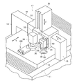
図2は、第1実施形態に係る形状測定装置200の概略斜視図である。図2に示すように、形状測定装置200は、形状測定機1と、この形状測定機1を駆動制御すると共に必要なデータ処理を実行するコンピュータシステム2とにより構成されている。
FIG. 2 is a schematic perspective view of the
形状測定機1は、次のように構成されている。即ち、架台11上には、被測定物を載置する測定テーブル13が装着されており、この測定テーブル13は、図示しないY軸駆動機構によってY軸方向に駆動される。架台11の両側縁中央部には上方に延びる支持アーム14、15が固定されており、この支持アーム14、15の両上端部を連結するようにX軸ガイド16が固定されている。このX軸ガイド16には、測定ユニット17が支持されている。測定ユニット17は、図示しないX軸駆動機構によってX軸ガイド16に沿って駆動される。なお、測定テーブル13の上には、上述した校正用治具100が配置されている。
The shape measuring machine 1 is configured as follows. In other words, a measurement table 13 on which an object to be measured is placed is mounted on the
図3は、第1実施形態に係る測定ユニット17の拡大斜視図である。図3に示すように、測定ユニット17は、X軸ガイド16に沿って移動可能にスライダ31を備えており、このスライダ31に一体にZ軸ガイド32が固定されている。このZ軸ガイド32には、支持板33がZ軸方向に摺動自在に設けられ、この支持板33に、画像測定用の撮像手段である撮像プローブ(第1プローブ、CCDカメラ)34と、非接触変位計であるレーザプローブ(第2プローブ)35とが併設されている。これにより、撮像プローブ34とレーザプローブ35とは、一定の位置関係を保ってX、Y、Zの3軸方向に同時に移動できるようになっている。撮像プローブ34には、撮像範囲を照明するための照明装置36が付加されている。レーザプローブ35の近傍位置には、レーザプローブ35のレーザビームによるワークの測定位置を確認するために、測定位置の周辺を撮像するCCDカメラ38と、レーザプローブ35の測定位置を照明するための照明装置39とが設けられている。レーザプローブ35は、撮像ユニット17の移動の際にレーザプローブ35を退避するための上下動機構40と、レーザビームの方向性を最適な方向に適合させるための回転機構41とにより支持されている。
FIG. 3 is an enlarged perspective view of the
上記構成を換言すると、撮像プローブ(第1プローブ)34は、被測定物からの反射光に基づく画像(落射照明光による画像)を撮像することにより被測定物の形状に関する情報を取得する。また、レーザプローブ(第2プローブ)35は、撮像プローブ34と異なる位置に設けられ被測定物の形状に関する情報を取得する。
In other words, the imaging probe (first probe) 34 acquires information related to the shape of the object to be measured by capturing an image based on the reflected light from the object to be measured (an image by incident illumination light). The laser probe (second probe) 35 is provided at a position different from that of the
コンピュータシステム2は、コンピュータ本体21、キーボード22、ジョイスティックボックス(以下、J/Sと呼ぶ)23、マウス24、CRT25、及びプリンタ26を備えて構成されている。
The
コンピュータ本体21は、図4に示すように構成されている。図4は、第1実施形態に係るコンピュータ本体21を示すブロック図である。
The computer
図4に示すように、撮像プローブ34から入力される画像情報は、インタフェース(以下、I/Fと呼ぶ)51aを介して画像メモリ52に格納される。レーザプローブ35から入力される情報は、インタフェース51bを介してHDD53に格納される。
As shown in FIG. 4, the image information input from the
また、図示しないCADシステムにより作成される被測定物のCADデータは、例えば、CADデータによるオフラインティーチングが実行される場合、I/F54を介してCPU(制御部)55に入力され、CPU55で画像形式を変換された後、画像メモリ52に格納される。画像メモリ52に格納された画像情報は、表示制御部56を介してCRT25に表示される。
In addition, CAD data of an object to be measured created by a CAD system (not shown) is input to a CPU (control unit) 55 via an I /
一方、キーボード22、J/S23、及びマウス24から入力されるコード情報及び位置情報等は、I/F56を介してCPU55に入力される。CPU55は、ROM57に格納されたマクロプログラム及びHDD53からI/F58を介してRAM59に格納された測定実行プログラム、オフセット算出プログラム等に従って測定実行処理、オフセット算出処理等を実行する。
On the other hand, code information, position information, and the like input from the
CPU55は、HDD53から測定実行プログラムを読み出し、測定部として機能する。また、CPU55は、HDD53からオフセット算出プログラムを読み出し、オフセット算出部として機能する。ここで、測定部は、撮像プローブ34及びレーザプローブ35により校正用治具100を測定して撮像測定結果(第1測定結果)及びレーザプローブ測定結果(第2測定結果)を求める。また、オフセット算出部は、撮像測定結果及びレーザプローブ測定結果を比較して撮像プローブ34とレーザプローブ35と間のオフセットを算出する。
The
HDD53は、CADデータ、測定実行プログラム、オフセット算出プログラム等を格納する記録媒体である。RAM59は、各種プログラムを格納する他、各種処理のワーク領域を提供する。
The
[第1実施形態に係る形状測定装置200のオフセット算出動作]
次に、図5〜図8を参照して、第1実施形態に係る形状測定装置200のオフセット算出動作について説明する。第1実施形態に係る形状測定装置200は、第1及び第2のオフセット算出動作を実行可能に構成されている。図5は、第1実施形態に係る形状測定装置200の第1のオフセット算出動作を示すフローチャートである。図6は、後述する画像IM1の測定の概略を説明する図である。図7は、撮像プローブ34による画像IM1及びその輝度情報IMa1を示す図である。図8は、第1実施形態に係る形状測定装置200の第2のオフセット算出動作を示すフローチャートである。なお、以下に示す動作は、制御部(CPU)55がHDD53に格納されたプログラムを読み出し実行することにより実現される。
[Offset calculation operation of the
Next, the offset calculation operation of the
先ず、第1のオフセット算出動作について説明する。第1のオフセット算出動作は、高倍率で焦点深度の浅い光学系を有した撮像プローブに適している。 First, the first offset calculation operation will be described. The first offset calculation operation is suitable for an imaging probe having an optical system with a high magnification and a shallow depth of focus.
図5に示すように、はじめに、制御部55は、撮像プローブ34を用いて、基準球112の輪郭部に合わせるようにフォーカス動作を行い(焦点を合わせ)、フォーカス高さZを調整する(ステップS101)。ここで、フォーカス高さZは、テーブル13と撮像プローブ34との間の距離を示す。
As shown in FIG. 5, first, the
続いて、制御部55は、撮像プローブ34を用いて、校正用治具100からの反射光に基づく画像IM1を測定する(ステップS102)。
Subsequently, the
ここで、上記ステップS102の動作の概略は、図6のようになる。すなわち、図6に示すように、基準球112の頂点付近に照射された光L1は、上方に正反射する。また、反射板111の上面に照射された光L2は、上方に正反射する。一方、基準球112の頂点付近以外の領域に照射された光L3は、正反射されず撮像プローブ34には入射しない。よって、撮像プローブ34は、光L1、L2の反射光に基づく画像IM1を測定する。
Here, the outline of the operation in step S102 is as shown in FIG. That is, as shown in FIG. 6, the light L1 irradiated near the apex of the
画像IM1には、図7に示すように、外径Dをもつドーナツ状の暗部AR1が表示される。この画像IM1の輝度情報IMa1においては、基準球112と反射板111との境界部分(エッジ)が、高コントラストで示される。
In the image IM1, a donut-shaped dark part AR1 having an outer diameter D is displayed as shown in FIG. In the luminance information IMa1 of the image IM1, the boundary portion (edge) between the
再び図5に示すように、続いて、制御部55は、画像IM1、及びフォーカス高さZに基づいて基準球112の中心座標P1(XP1、YP1、ZP1)を算出する(ステップS103)。ここで、制御部55は、画像IM1について3箇所以上の暗部AR1の輪郭部(エッジ)を特定することで、中心座標P1を求める。
As shown in FIG. 5 again, subsequently, the
次に、制御部55は、レーザプローブ35を用いて校正用治具100(基準球112)の表面を4箇所以上測定する(ステップS104)。続いて、制御部55は、レーザプローブ35による測定結果に基づき基準球112の中心座標P2(XP2、YP2、ZP2)を算出する(ステップS105)。
Next, the
そして、制御部55は、以下に示す(数式1)のように、撮像プローブ34とレーザプローブ35との間のオフセットOを算出する(ステップS106)。以上で、第1のオフセット算出動作は、終了する。
And the

なお、上記第1のオフセット算出動作を換言すると、以下のようになる。すなわち、制御部55は、ステップS101〜S105において、撮像プローブ34及びレーザプローブ35により校正用治具100を測定して中心座標(第1測定結果)P1、中心座標(第2測定結果)P2を求める。また、制御部55は、ステップS106において、中心座標P1及び中心座標P2を比較してオフセットOを算出する。
In other words, the first offset calculation operation is as follows. That is, in steps S101 to S105, the
次に、第2のオフセット算出動作について説明する。第2のオフセット算出動作は、低倍率で焦点深度の深い光学系を有した撮像プローブに適している。 Next, the second offset calculating operation will be described. The second offset calculation operation is suitable for an imaging probe having an optical system with a low magnification and a deep focal depth.
図8に示すように、先ず、制御部55は、撮像プローブ34を用いて、フォーカス動作を行い(焦点を合わせ)、フォーカス高さZaを調整する(ステップS201)。ここで、ステップS201におけるフォーカス動作は、基準球112の輪郭部が最も鮮明に観察できる高さに、フォーカス高さZaを合わせるように行う。
なお、フォーカス高さZaは、基準球112の中心位置を正確に捉えていない可能性が高いため、後述する処理に用いることはない。
As shown in FIG. 8, first, the
Note that the focus height Za is not likely to accurately capture the center position of the
次に、制御部55は、撮像プローブ34を用いて、校正用治具100からの反射光に基づく画像IM1を測定する(ステップS202)。
Next, the
続いて、制御部55は、画像IM1に基づいて基準球112の座標値P3(P3=XP3、YP3)を算出する(ステップS203)。なお、座標値P3は、Z軸方向を除く座標(XY座標)を示す。
Subsequently, the
次に、制御部55は、レーザプローブ35を用いて校正用治具100(基準球112)の表面を4箇所以上測定する(ステップS204)。続いて、制御部55は、レーザプローブ35による測定結果に基づき基準球112の座標値P4(P4=XP4、YP4)を算出する(ステップS205)。なお、座標値P4は、Z軸方向を除く座標(XY座標)を示す。
Next, the
次に、制御部55は、以下に示す(数式2)のように、座標差E1(XE、YE)を算出する(ステップS206)。なお、座標差E1は、撮像プローブ34とレーザプローブ35との間のXY方向のオフセットを意味する。
Next, the
![]()
![]()
続いて、制御部55は、撮像プローブ34を用いて、基準ブロック113の上面に合わせるようにフォーカス動作を行い、フォーカス高さZbを調整する(ステップS207)。
Subsequently, the
次に、制御部55は、撮像プローブ34を用いて、校正用治具100からの正反射光に基づく画像IM1を測定する(ステップS208)。続いて、制御部55は、画像IM1、及びフォーカス高さZbに基づき基準ブロック113の上面の所定位置の座標値P5(XP5、YP5、ZP5)を算出する(ステップS209)。
Next, the
次に、制御部55は、レーザプローブ35を用いて、所定位置にて基準ブロック113の上面を測定する(ステップS210)。このステップS210において、制御部55は、レーザプローブ35にて上記測定を行わせるため、レーザプローブ35を座標差E1(XE、YE)だけ移動させる。
Next, the
続いて、制御部55は、レーザプローブ35による測定結果に基づき基準ブロック113の上面の所定位置の座標値P6(XP6、YP6、ZP6)を算出する(ステップS211)。
Subsequently, the
次に、制御部55は、以下に示す(数式3)のように、座標差E2(ZE)を算出する(ステップS212)。なお、座標差E2は、撮像プローブ34とレーザプローブ35との間のZ方向のオフセットを意味する。
Next, the
![]()
![]()
そして、制御部55は、以下に示す(数式4)のように、座標差E1,E2に基づき撮像プローブ34とレーザプローブ35との間のオフセットOa(XOa、YOa、ZOa)を算出する(ステップS213)。以上で、第2のオフセット算出動作は、終了する。
And the
![]()
![]()
なお、上記第2のオフセット算出動作を換言すると、以下のようになる。すなわち、制御部55は、ステップS201〜S212において、撮像プローブ34及びレーザプローブ35により校正用治具100を測定して座標値(第1測定結果)P3,P5、及び座標値(第2測定結果)P4,P6を求める。また、制御部55は、ステップS213において、座標値P3,P5及び座標値P4,P6を比較してオフセットOaを算出する。
In other words, the second offset calculating operation is as follows. That is, in steps S201 to S212, the
(第1実施形態に係る効果)
次に、第1実施形態に係る校正用治具100、及び形状測定装置200、及びそのオフセット算出方法の効果について説明する。第1実施形態に係る校正用治具100は、従来の校正治具のように、部品を組み立てた状態での調整加工が不要となるため、価格を安く抑えることができる。
(Effect according to the first embodiment)
Next, effects of the
第1実施形態に係る校正用治具100は、高コントラストで基準球112のエッジを撮像することができる。これにより、高精度で、形状測定装置200の校正(オフセットの算出)を行うことができる。
The
第1実施形態に係る校正用治具100は、反射板111により光を正反射させるので、照射した光量に対する反射光の損失を抑制することができる。したがって、第1実施形態に係る校正用治具100は、少ない光量でも十分なコントラストをもつ画像を測定することができる。すなわち、第1実施形態に係る校正用治具100は、照明光による治具自体の温度上昇に伴う線膨張を抑制し、測定誤差を低減させることができる。また、第1実施形態に係る校正用治具100は、明るい光源が不要であるので、省エネルギー化が図れる。
Since the
また、第1実施形態に係る形状測定装置200、及びそのオフセット算出方法は、上記構成を有する校正用治具100と同様の効果を奏する。
Moreover, the
[第2実施形態]
(第2実施形態に係る校正用治具の構成)
次に、図9を参照して、第2実施形態に係る校正用治具100aの構成について説明する。図9は、本発明の第2実施形態に係る校正用治具100aの斜視図である。なお、第2実施形態において、第1実施形態と同様の構成については、同一符号を付し、その説明を省略する。
[Second Embodiment]
(Configuration of calibration jig according to the second embodiment)
Next, the configuration of the
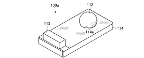
校正用治具100aは、撮像プローブ34、及びレーザプローブ35により測定されるものである。校正用治具100aは、透過板114と、基準球112と、基準ブロック113とを備える。つまり、校正用治具100aは、第1実施形態の反射板111の代わりに、透過板114を備える。
The
透過板114は、基準球112を下方から支持する。透過板114は、光を透過するように構成されている。透過板114は、例えば、ガラスにて構成されている。透過板114は、矩形板状の形状を有する。透過板114は、その上面に窪んだ凹部114aを有する。
The
ここで、形状測定装置において透過照明光を用いた場合、基準球112にて遮られた光の分布が画像として測定される。このとき、基準球112が光軸に対して傾いて配置されたとしても、その配置は、測定される画像に影響を及ぼさない(常に一定の円形の暗部が測定される)。よって、透過板114は、平行度を要求されない。
Here, when transmitted illumination light is used in the shape measuring apparatus, the distribution of light blocked by the
基準球112は、その下部が透過板114の凹部114aに嵌合するように設けられている。
The
基準ブロック113は、透過板114の一端上部に設けられている。
The
(第2実施形態に係る形状測定装置の構成)
次に、図10を参照して、第2実施形態に係る形状測定装置の構成について説明する。図10は、第2実施形態に係る測定ユニット17の拡大斜視図である。
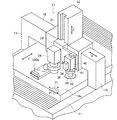
(Configuration of the shape measuring apparatus according to the second embodiment)
Next, the configuration of the shape measuring apparatus according to the second embodiment will be described with reference to FIG. FIG. 10 is an enlarged perspective view of the
第2実施形態に係る形状測定機は、第1実施形態と異なる測定テーブル13aを有する。また、第2実施形態に係る形状測定機は、さらに照明装置71を有する。
The shape measuring machine according to the second embodiment has a measurement table 13a different from the first embodiment. The shape measuring machine according to the second embodiment further includes an
測定テーブル13aは、光を透過するように構成されている。なお、測定テーブル13a上には、上述した校正用治具100aが設けられている。
The measurement table 13a is configured to transmit light. The
照明装置71は、測定テーブル13a内に設けられている。照明装置71は、測定テーブル13aを介して、上方に光を照射するように構成されている。照明装置71は、撮像プローブ34の移動に同期して、XY方向に移動可能に構成されている。
The
つまり、第2実施形態において、撮像プローブ34(第3プローブ)は、被測定物からの透過光に基づく画像(透過照明光による画像)を撮像することにより被測定物の形状に関する情報を取得するように構成されている。 That is, in the second embodiment, the imaging probe 34 (third probe) acquires information on the shape of the object to be measured by capturing an image based on the transmitted light from the object to be measured (an image by transmitted illumination light). It is configured as follows.
(第2実施形態に係る形状測定装置のオフセット算出動作)
次に、図11及び図12を参照して、第2実施形態に係る形状測定装置のオフセット算出動作について説明する。第2実施形態に係る形状測定装置は、第1実施形態と同様に、第1及び第2のオフセット算出動作を実行可能に構成されている。図11は、後述する画像IM4の測定の概略を説明する図である。図13は、撮像プローブ34による画像IM4及びその輝度情報IMa4を示す図である。
(Offset calculation operation of the shape measuring apparatus according to the second embodiment)
Next, an offset calculation operation of the shape measuring apparatus according to the second embodiment will be described with reference to FIGS. The shape measuring apparatus according to the second embodiment is configured to be able to execute the first and second offset calculation operations, as in the first embodiment. FIG. 11 is a diagram for explaining the outline of measurement of an image IM4 described later. FIG. 13 is a diagram illustrating an image IM4 and its luminance information IMa4 obtained by the
第2実施形態に係る形状測定装置のオフセット算出動作において、撮像プローブ34による画像の測定方法が、第1実施形態と異なる。
In the offset calculation operation of the shape measuring apparatus according to the second embodiment, the image measurement method using the
制御部55は、撮像プローブ34を用いて、校正用治具100aからの透過光に基づく画像IM4を測定する。すなわち、図11に示すように、照明部71から基準球112に照射された光La1は、基準球112にて遮られる。一方、基準球112の以外の領域(透過板114)に照射された光La2は、透過板114を介して透過される。よって、撮像プローブ34は、光La2(透過光)に基づく画像IM4を測定する。
The
画像IM4には、図12に示すように、直径Dをもつ円形状の暗部AR2が表示される。この画像IM4の輝度情報IMa4においては、基準球112と透過板114との境界部分(エッジ)が、高コントラストで示される。
In the image IM4, a circular dark part AR2 having a diameter D is displayed as shown in FIG. In the luminance information IMa4 of the image IM4, a boundary portion (edge) between the
(第2実施形態に係る効果)
次に、第2実施形態に係る効果を説明する。第2実施形態に係る校正用治具100aは、第1実施形態に係る反射板111の代わりに、平行度を要求されない透過板114を有する。したがって、第2実施形態に係る校正用治具100aは、第1実施形態よりも安価に製造可能である。
(Effect according to the second embodiment)
Next, effects according to the second embodiment will be described. A
また、第2実施形態に係る形状測定装置、及びそのオフセット算出方法は、上記校正用治具100と同様の効果を奏する。
Further, the shape measuring apparatus and the offset calculation method according to the second embodiment have the same effects as the
以上、発明の一実施形態を説明したが、本発明はこれらに限定されるものではなく、発明の趣旨を逸脱しない範囲内において、様々な置換、追加、削除等が可能である。例えば、上記実施形態では、Z方向のオフセット値の算出のため基準ブロック113を備えているが、基準球112の頂点への撮像プローブ34のオートフォーカスが精度良く行うことができる場合には基準ブロック113は省略してもよい。また、基準球112の支持方法として、基準球112を反射板111(又は透過板114)に嵌合する方法が記述されているが、これに限定されるものではない。例えば、単純に基準球112を反射板111(又は透過板114)に接着することで支持してもよい。
Although one embodiment of the invention has been described above, the present invention is not limited to these embodiments, and various substitutions, additions, deletions, and the like are possible without departing from the spirit of the invention. For example, in the above embodiment, the
また、上記実施形態の第2のオフセット算出動作において、制御部55は、基準ブロック113の上面の所定位置を測定する(ステップS207)ものとしたが、基準球112の頂点部分を測定するものとしても良いし、反射板111や透過板114の平面度が良好であれば、板上の任意の位置を測定するものとしても良い。
In the second offset calculation operation of the above embodiment, the
また、上記実施形態における形状測定装置は、レーザプローブ35を有する構成であるが、レーザプローブ35の代わりにタッチプローブ(接触型プローブ)を有する構成であってもよいし、倣いプローブを有する構成であってもよい。
In addition, the shape measuring apparatus in the above embodiment has a configuration having the
100、100a…校正用治具、111…反射板、 112…基準球、 113…基準ブロック、 114…透過板、 200…形状測定装置、 11…架台、 13、13a…測定テーブル、 14、15…支持アーム、 16…X軸ガイド、 17…測定ユニット、34…撮像プローブ、38…CCDカメラ、 35…レーザプローブ、36、39、71…照明装置、 40…上下動機構、 41…回転機構。
DESCRIPTION OF
Claims (8)
前記基準球を下方から支持し且つ前記基準球が上方から照明された場合の光を正反射させる反射板と
を備えることを特徴とする校正用治具。 A reference sphere,
A calibration jig, comprising: a reflector that supports the reference sphere from below and regularly reflects light when the reference sphere is illuminated from above.
ことを特徴とする請求項1記載の校正用治具。 The calibration jig according to claim 1, wherein the surface of the reference sphere is configured by a mirror surface.
を備えることを特徴とする請求項1又は請求項2記載の校正用治具。 The calibration jig according to claim 1, further comprising a reference block formed on the reflection plate and having a flat upper surface.
前記基準球を下方から支持し且つ光を透過させる透過板と
を備えることを特徴とする校正用治具。 A reference sphere,
A calibration jig comprising: a transmission plate that supports the reference sphere from below and transmits light.
前記第1プローブと異なる位置に設けられ前記被測定物の形状に関する情報を取得する第2プローブと、
前記第1プローブ及び前記第2プローブにより測定される校正用治具と、
前記第1プローブ及び前記第2プローブにより前記校正用治具を測定して第1測定結果及び第2測定結果を求める測定部と、
前記第1測定結果及び前記第2測定結果を比較してオフセットを算出するオフセット算出部とを備え、
前記校正用治具は、
基準球と、
前記基準球を下方から支持し且つ前記基準球が上方から照明された場合の光を正反射させる反射板とを備える
ことを特徴とする形状測定装置。 A first probe that acquires information on the shape of the object to be measured by capturing an image based on reflected light from the object to be measured;
A second probe that is provided at a position different from the first probe and acquires information on the shape of the object to be measured;
A calibration jig measured by the first probe and the second probe;
A measurement unit for measuring the calibration jig with the first probe and the second probe to obtain a first measurement result and a second measurement result;
An offset calculation unit that calculates an offset by comparing the first measurement result and the second measurement result;
The calibration jig is
A reference sphere,
A shape measuring apparatus comprising: a reflector that supports the reference sphere from below and regularly reflects light when the reference sphere is illuminated from above.
前記第3プローブと異なる位置に設けられ前記被測定物の形状に関する情報を取得する第2プローブと、
前記第3プローブ及び前記第2プローブにより測定される校正用治具と、
前記第3プローブ及び前記第2プローブにより前記校正用治具を測定して第3測定結果及び第2測定結果を生成する測定部と、
前記第3測定結果及び前記第2測定結果を比較してオフセットを求めるオフセット算出部とを備え、
前記校正用治具は、
基準球と、
前記基準球を下方から支持し且つ光を透過させる透過板とを備える
ことを特徴とする形状測定装置。 A third probe for acquiring information related to the shape of the object to be measured by capturing an image based on transmitted light from the object to be measured;
A second probe that is provided at a different position from the third probe and acquires information on the shape of the object to be measured;
A calibration jig measured by the third probe and the second probe;
A measurement unit that measures the calibration jig with the third probe and the second probe to generate a third measurement result and a second measurement result;
An offset calculation unit for obtaining an offset by comparing the third measurement result and the second measurement result,
The calibration jig is
A reference sphere,
A shape measuring apparatus comprising: a transmission plate that supports the reference sphere from below and transmits light.
前記第1プローブ及び前記第2プローブにより前記校正用治具を測定して第1測定結果及び第2測定結果を求める測定ステップと、
前記第1測定結果及び前記第2測定結果を比較してオフセットを算出するオフセット算出ステップと
を備えることを特徴とするオフセット算出方法。 A first probe that acquires information on the shape of the measurement object by capturing an image based on reflected light from the measurement object, and information on the shape of the measurement object that is provided at a different position from the first probe. A second probe to be obtained; and a calibration jig to be measured by the first probe and the second probe. The calibration jig supports a reference sphere, the reference sphere from below, and the reference An offset calculation method for calculating an offset of the shape measuring device using a shape measuring device including a reflector that regularly reflects light when a sphere is illuminated from above,
A measurement step of measuring the calibration jig with the first probe and the second probe to obtain a first measurement result and a second measurement result;
An offset calculation method comprising: an offset calculation step of calculating an offset by comparing the first measurement result and the second measurement result.
前記第3プローブ及び前記第2プローブにより前記校正用治具を測定して第3測定結果及び第2測定結果を求める測定ステップと、
前記第3測定結果及び前記第2測定結果を比較してオフセットを算出するオフセット算出ステップと
を備えることを特徴とするオフセット算出方法。 A third probe that acquires information related to the shape of the object to be measured by capturing an image based on transmitted light from the object to be measured, and information related to the shape of the object to be measured that is provided at a different position from the third probe A second probe to be acquired; a calibration jig to be measured by the third probe and the second probe; and the calibration jig supports a reference sphere, the reference sphere from below and emits light. An offset calculation method for calculating an offset of the shape measuring device using a shape measuring device including a transmitting plate to transmit,
A measurement step of measuring the calibration jig with the third probe and the second probe to obtain a third measurement result and a second measurement result;
An offset calculation method comprising: an offset calculation step of calculating an offset by comparing the third measurement result and the second measurement result.
Priority Applications (4)
| Application Number | Priority Date | Filing Date | Title |
|---|---|---|---|
| JP2008180084A JP5623009B2 (en) | 2008-07-10 | 2008-07-10 | Calibration jig, shape measuring device, and offset calculation method |
| US12/457,782 US8139229B2 (en) | 2008-07-10 | 2009-06-22 | Calibrating jig, profile measuring device, and method of offset calculation |
| EP09163697.7A EP2144035B1 (en) | 2008-07-10 | 2009-06-25 | Calibrating jig, profile measuring device, and method of offset calculation |
| US13/369,079 US8416426B2 (en) | 2008-07-10 | 2012-02-08 | Calibrating jig, profile measuring device, and method of offset calculation |
Applications Claiming Priority (1)
| Application Number | Priority Date | Filing Date | Title |
|---|---|---|---|
| JP2008180084A JP5623009B2 (en) | 2008-07-10 | 2008-07-10 | Calibration jig, shape measuring device, and offset calculation method |
Publications (2)
| Publication Number | Publication Date |
|---|---|
| JP2010019671A true JP2010019671A (en) | 2010-01-28 |
| JP5623009B2 JP5623009B2 (en) | 2014-11-12 |
Family
ID=41228278
Family Applications (1)
| Application Number | Title | Priority Date | Filing Date |
|---|---|---|---|
| JP2008180084A Active JP5623009B2 (en) | 2008-07-10 | 2008-07-10 | Calibration jig, shape measuring device, and offset calculation method |
Country Status (3)
| Country | Link |
|---|---|
| US (2) | US8139229B2 (en) |
| EP (1) | EP2144035B1 (en) |
| JP (1) | JP5623009B2 (en) |
Cited By (1)
| Publication number | Priority date | Publication date | Assignee | Title |
|---|---|---|---|---|
| JP2017150993A (en) * | 2016-02-25 | 2017-08-31 | 株式会社ミツトヨ | Inner wall measurement device and offset amount calculation method |
Families Citing this family (9)
| Publication number | Priority date | Publication date | Assignee | Title |
|---|---|---|---|---|
| US7908756B2 (en) * | 2007-10-12 | 2011-03-22 | Los Alamos National Security, Llc | Integrated calibration sphere and calibration step fixture for improved coordinate measurement machine calibration |
| DE102009045515B3 (en) * | 2009-10-09 | 2011-03-03 | Dreier Lasermesstechnik Gmbh | Device for checking the accuracy of machine tools and measuring devices |
| CN101852593A (en) * | 2010-05-06 | 2010-10-06 | 深南电路有限公司 | Automatic optical inspection equipment, light measuring tool plate and light adjusting method thereof |
| EP2492635B1 (en) * | 2011-02-22 | 2013-05-29 | Siemens Aktiengesellschaft | Calibration method for a spherical measuring probe |
| EP3507570A1 (en) * | 2016-09-01 | 2019-07-10 | Hexagon Metrology, Inc | Conformance test artifact for coordinate measuring machine |
| US10509071B2 (en) * | 2016-11-18 | 2019-12-17 | Taiwan Semiconductor Manufacturing Co., Ltd. | Method and system for aligning probe card in semiconductor device testing |
| JP7161905B2 (en) * | 2018-10-15 | 2022-10-27 | アルテミラ株式会社 | Can lid inspection machine and camera position adjustment method |
| JP2021148458A (en) | 2020-03-16 | 2021-09-27 | 株式会社東芝 | Shape measurement method and shape measurement device |
| CN111467050B (en) * | 2020-05-08 | 2020-11-24 | 杭州键嘉机器人有限公司 | Orthopedic surgery robot marks reflection of light ball base |
Citations (6)
| Publication number | Priority date | Publication date | Assignee | Title |
|---|---|---|---|---|
| JP2001165630A (en) * | 1999-12-14 | 2001-06-22 | Mitsutoyo Corp | Sensor calibration device for surface property measuring machine |
| JP2003207332A (en) * | 2002-01-09 | 2003-07-25 | Dainippon Screen Mfg Co Ltd | Width measuring device and thin film position measuring device |
| JP2004170400A (en) * | 2002-10-30 | 2004-06-17 | Hitachi Kokusai Electric Inc | Method and system for measuring dimensions |
| JP2006292775A (en) * | 2000-12-08 | 2006-10-26 | Hitachi Metals Ltd | Method of measuring shape of spherical body |
| JP2007078635A (en) * | 2005-09-16 | 2007-03-29 | Mitsutoyo Corp | Calibration fixture, and offset calculation method of image measuring machine |
| JP2007205864A (en) * | 2006-02-01 | 2007-08-16 | Reitetsukusu:Kk | Substrate inspecting apparatus and substrate inspecting method |
Family Cites Families (6)
| Publication number | Priority date | Publication date | Assignee | Title |
|---|---|---|---|---|
| US3708378A (en) | 1970-11-27 | 1973-01-02 | Minnesota Mining & Mfg | Heat-sensitive retro-reflective imaging sheet |
| JP3511450B2 (en) | 1997-09-12 | 2004-03-29 | 株式会社ミツトヨ | Position calibration method for optical measuring device |
| JP2005106614A (en) * | 2003-09-30 | 2005-04-21 | Tdk Corp | Jig for calibrating three-dimensional camera, and method for calibrating camera |
| KR20070012459A (en) | 2004-05-10 | 2007-01-25 | 코닌클리케 필립스 일렉트로닉스 엔.브이. | Device and method for optical precision measurement |
| DE102006014509A1 (en) * | 2006-03-22 | 2007-09-27 | Carl Zeiss Industrielle Messtechnik Gmbh | Test specimen and method for measuring a coordinate measuring machine |
| JP2008180084A (en) | 2008-04-02 | 2008-08-07 | Saicon Industry Co Ltd | Car stop block |
-
2008
- 2008-07-10 JP JP2008180084A patent/JP5623009B2/en active Active
-
2009
- 2009-06-22 US US12/457,782 patent/US8139229B2/en not_active Expired - Fee Related
- 2009-06-25 EP EP09163697.7A patent/EP2144035B1/en not_active Not-in-force
-
2012
- 2012-02-08 US US13/369,079 patent/US8416426B2/en active Active
Patent Citations (6)
| Publication number | Priority date | Publication date | Assignee | Title |
|---|---|---|---|---|
| JP2001165630A (en) * | 1999-12-14 | 2001-06-22 | Mitsutoyo Corp | Sensor calibration device for surface property measuring machine |
| JP2006292775A (en) * | 2000-12-08 | 2006-10-26 | Hitachi Metals Ltd | Method of measuring shape of spherical body |
| JP2003207332A (en) * | 2002-01-09 | 2003-07-25 | Dainippon Screen Mfg Co Ltd | Width measuring device and thin film position measuring device |
| JP2004170400A (en) * | 2002-10-30 | 2004-06-17 | Hitachi Kokusai Electric Inc | Method and system for measuring dimensions |
| JP2007078635A (en) * | 2005-09-16 | 2007-03-29 | Mitsutoyo Corp | Calibration fixture, and offset calculation method of image measuring machine |
| JP2007205864A (en) * | 2006-02-01 | 2007-08-16 | Reitetsukusu:Kk | Substrate inspecting apparatus and substrate inspecting method |
Cited By (1)
| Publication number | Priority date | Publication date | Assignee | Title |
|---|---|---|---|---|
| JP2017150993A (en) * | 2016-02-25 | 2017-08-31 | 株式会社ミツトヨ | Inner wall measurement device and offset amount calculation method |
Also Published As
| Publication number | Publication date |
|---|---|
| EP2144035B1 (en) | 2014-09-10 |
| US20100007895A1 (en) | 2010-01-14 |
| EP2144035A1 (en) | 2010-01-13 |
| US8416426B2 (en) | 2013-04-09 |
| US8139229B2 (en) | 2012-03-20 |
| US20120188558A1 (en) | 2012-07-26 |
| JP5623009B2 (en) | 2014-11-12 |
Similar Documents
| Publication | Publication Date | Title |
|---|---|---|
| JP5623009B2 (en) | Calibration jig, shape measuring device, and offset calculation method | |
| JP4791118B2 (en) | Image measuring machine offset calculation method | |
| TW201423033A (en) | Shape measuring apparatus, structure manufacturing system, stage apparatus, shape measuring method, structure manufacturing method, program, and recording medium | |
| JPH10311711A (en) | Optical profile sensor | |
| JP6461609B2 (en) | Interference objective lens and optical interference measurement apparatus | |
| US7869060B2 (en) | Jig for measuring an object shape and method for measuring a three-dimensional shape | |
| JP2015059825A (en) | Three-dimensional measuring apparatus | |
| US8305587B2 (en) | Apparatus for the optical inspection of wafers | |
| CN111406197A (en) | Transparent or translucent material curved surface contour detection system | |
| KR101067996B1 (en) | Inspection method of line width measuring device | |
| CN110502947B (en) | Structured light depth measuring system, method for measuring information code depth and data processing method | |
| JP5649926B2 (en) | Surface shape measuring apparatus and surface shape measuring method | |
| US8149383B2 (en) | Method for determining the systematic error in the measurement of positions of edges of structures on a substrate resulting from the substrate topology | |
| TWI545315B (en) | Method for producing a mirror substrate blank of titanium-doped silica glass for euv lithography, and system for determining the position of defects in a blank | |
| JP5358898B2 (en) | Optical surface shape measuring method and apparatus, and recording medium | |
| JP6880396B2 (en) | Shape measuring device and shape measuring method | |
| JP2007232629A (en) | Lens shape measuring instrument | |
| CN217930168U (en) | Combined type imager | |
| JP5430473B2 (en) | Surface shape measuring device | |
| JP6840590B2 (en) | Calibration system, calibration jig, calibration method, and calibration program | |
| JP2022036078A (en) | measuring device | |
| JP2020092140A (en) | Position measuring device and position measuring method | |
| JP2012181021A (en) | Contact type probe and shape measurement device | |
| JP2012002573A (en) | Non-contact shape measuring apparatus | |
| JP2008139071A (en) | Three-dimensional shape measuring system, three-dimensional shape measuring instrument, solid measuring object, and alignment method |
Legal Events
| Date | Code | Title | Description |
|---|---|---|---|
| A621 | Written request for application examination |
Free format text: JAPANESE INTERMEDIATE CODE: A621 Effective date: 20110601 |
|
| A977 | Report on retrieval |
Free format text: JAPANESE INTERMEDIATE CODE: A971007 Effective date: 20120711 |
|
| A131 | Notification of reasons for refusal |
Free format text: JAPANESE INTERMEDIATE CODE: A131 Effective date: 20120717 |
|
| A521 | Request for written amendment filed |
Free format text: JAPANESE INTERMEDIATE CODE: A523 Effective date: 20120913 |
|
| A02 | Decision of refusal |
Free format text: JAPANESE INTERMEDIATE CODE: A02 Effective date: 20130604 |
|
| A521 | Request for written amendment filed |
Free format text: JAPANESE INTERMEDIATE CODE: A523 Effective date: 20130910 |
|
| A61 | First payment of annual fees (during grant procedure) |
Free format text: JAPANESE INTERMEDIATE CODE: A61 Effective date: 20140924 |
|
| R150 | Certificate of patent or registration of utility model |
Ref document number: 5623009 Country of ref document: JP Free format text: JAPANESE INTERMEDIATE CODE: R150 |
|
| R250 | Receipt of annual fees |
Free format text: JAPANESE INTERMEDIATE CODE: R250 |
|
| R250 | Receipt of annual fees |
Free format text: JAPANESE INTERMEDIATE CODE: R250 |