JP2010014718A - Method and system for 3d digitalization of object - Google Patents
Method and system for 3d digitalization of object Download PDFInfo
- Publication number
- JP2010014718A JP2010014718A JP2009160969A JP2009160969A JP2010014718A JP 2010014718 A JP2010014718 A JP 2010014718A JP 2009160969 A JP2009160969 A JP 2009160969A JP 2009160969 A JP2009160969 A JP 2009160969A JP 2010014718 A JP2010014718 A JP 2010014718A
- Authority
- JP
- Japan
- Prior art keywords
- feature points
- feature
- determined
- point
- coordinates
- Prior art date
- Legal status (The legal status is an assumption and is not a legal conclusion. Google has not performed a legal analysis and makes no representation as to the accuracy of the status listed.)
- Granted
Links
Images

Classifications
-
- G—PHYSICS
- G01—MEASURING; TESTING
- G01B—MEASURING LENGTH, THICKNESS OR SIMILAR LINEAR DIMENSIONS; MEASURING ANGLES; MEASURING AREAS; MEASURING IRREGULARITIES OF SURFACES OR CONTOURS
- G01B11/00—Measuring arrangements characterised by the use of optical techniques
- G01B11/24—Measuring arrangements characterised by the use of optical techniques for measuring contours or curvatures
- G01B11/25—Measuring arrangements characterised by the use of optical techniques for measuring contours or curvatures by projecting a pattern, e.g. one or more lines, moiré fringes on the object
-
- G—PHYSICS
- G06—COMPUTING; CALCULATING OR COUNTING
- G06T—IMAGE DATA PROCESSING OR GENERATION, IN GENERAL
- G06T7/00—Image analysis
- G06T7/50—Depth or shape recovery
- G06T7/55—Depth or shape recovery from multiple images
- G06T7/593—Depth or shape recovery from multiple images from stereo images
-
- G—PHYSICS
- G01—MEASURING; TESTING
- G01B—MEASURING LENGTH, THICKNESS OR SIMILAR LINEAR DIMENSIONS; MEASURING ANGLES; MEASURING AREAS; MEASURING IRREGULARITIES OF SURFACES OR CONTOURS
- G01B2210/00—Aspects not specifically covered by any group under G01B, e.g. of wheel alignment, caliper-like sensors
- G01B2210/52—Combining or merging partially overlapping images to an overall image
-
- G—PHYSICS
- G06—COMPUTING; CALCULATING OR COUNTING
- G06T—IMAGE DATA PROCESSING OR GENERATION, IN GENERAL
- G06T2207/00—Indexing scheme for image analysis or image enhancement
- G06T2207/10—Image acquisition modality
- G06T2207/10004—Still image; Photographic image
- G06T2207/10012—Stereo images
Landscapes
- Engineering & Computer Science (AREA)
- Computer Vision & Pattern Recognition (AREA)
- Physics & Mathematics (AREA)
- General Physics & Mathematics (AREA)
- Theoretical Computer Science (AREA)
- Length Measuring Devices By Optical Means (AREA)
- Testing, Inspecting, Measuring Of Stereoscopic Televisions And Televisions (AREA)
Abstract
Description
本発明は、対象物の複数のカメラ画像を記録して組み合わせて、対象物の3D(3次元)座標を決定する、対象物を3D(3次元)デジタル化するための方法及び装置に関する。 The present invention relates to a method and apparatus for 3D (three-dimensional) digitization of an object, wherein a plurality of camera images of the object are recorded and combined to determine 3D (three-dimensional) coordinates of the object.
対象物の3Dデジタル化において、多くの場合、対象物の複数のカメラ画像を記録する必要がある。隣接するカメラ画像は互いに重なり合っている。それゆえ、これらのカメラ画像を、特に照合処理によって組み合わせることができる。 In 3D digitization of an object, in many cases, it is necessary to record a plurality of camera images of the object. Adjacent camera images overlap each other. Therefore, these camera images can be combined especially by the collation process.
本発明の目的は、対象物を3Dデジタル化するための前記の方法及び装置を改良することである。 The object of the present invention is to improve the method and apparatus described above for 3D digitizing an object.
本発明によれば、この目的は、請求項1及び請求項6の特徴により達成される。
According to the invention, this object is achieved by the features of
対象物の複数のカメラ画像を記録する。これらは、対象物の3D座標を決定するのに適したカメラ画像である。ストリップ投影方法、特に白色光ストリップ投影方法を適用することが特に可能である。しかしながら、レーザースキャナ方法、又は、対象物を3Dデジタル化することのできる何らかの他の方法を適用することも可能である。本発明を実施するために、対象物の3Dビューをカメラで記録するカメラベースの方法を特に使用することができる。 Record multiple camera images of the object. These are camera images suitable for determining the 3D coordinates of the object. It is particularly possible to apply a strip projection method, in particular a white light strip projection method. However, it is also possible to apply a laser scanner method or some other method that can 3D digitize an object. To implement the present invention, a camera-based method of recording a 3D view of an object with a camera can be used in particular.
対象物を3Dデジタル化する方法を実施するための装置は、投影機と、1つ又は複数のカメラとを備えていてもよい。投影機及び1つ又は複数のカメラは、3Dセンサに一体化されていてもよい。投影機は、対象物に光パターン、特にストリップパターン、中でも白色光ストリップを投影するのに適するものであってもよい。しかしながら、投影機は、対象物にレーザ光パターン、特に1つ又は複数のレーザ線を投影するのに適するものであってもよい。 An apparatus for implementing a method for 3D digitizing an object may comprise a projector and one or more cameras. The projector and one or more cameras may be integrated into the 3D sensor. The projector may be suitable for projecting a light pattern, particularly a strip pattern, especially a white light strip, onto an object. However, the projector may be suitable for projecting a laser light pattern, particularly one or more laser lines, onto an object.
1つ又は複数のカメラによって、対象物の複数のカメラ画像を記録することができる。このカメラ画像は、異なる視点(視野、視野角)から記録される。カメラ画像は、対象物の様々な領域をカバーし、これらの領域は、一般的には互いに部分的に重なり合っている。様々なカメラ画像を、特に3D照合処理によって組み合わせることができる。このようにして、対象物の比較的大きな領域、又は、対象物の全表面をカバーすることができる。 Multiple camera images of the object can be recorded by one or more cameras. This camera image is recorded from different viewpoints (viewing field, viewing angle). The camera image covers various areas of the object, and these areas generally overlap one another. Various camera images can be combined, especially by a 3D matching process. In this way, a relatively large area of the object or the entire surface of the object can be covered.
対象物が十分な3D構造を有している場合、個々の重なり合うカメラ画像を、3D照合処理によって互いに整合させることができる。しかしながら、従来技術の方法では、この照合には、測定シーケンスにおける手動操作がさらに必要である。なぜなら、様々なカメラ画像における対応する3D点を、データ記録に手作業で印付けする必要があるからである。このことは、操作労力を増やし、対象物の3Dデジタル化の効率を下げてしまう。 If the object has a sufficient 3D structure, the individual overlapping camera images can be matched to each other by a 3D matching process. However, in the prior art method, this verification further requires manual operation in the measurement sequence. This is because the corresponding 3D points in the various camera images need to be manually marked in the data record. This increases operating effort and reduces the efficiency of 3D digitization of the object.
本発明によれば、対象物の写真を撮影する。これらの写真から、対象物の2D特徴点を決定する。2D特徴点として、対象物の角、すなわち対象物の2つ以上の辺が交わる部分を特に使用してもよい。しかしながら、写真における、特徴的な周囲部分を有する他の点を、2D特徴点として使用することも可能である。2D特徴点は、自動的に、すなわち人が手動で操作せずに決定することができる。 According to the present invention, a photograph of an object is taken. From these photographs, the 2D feature points of the object are determined. As the 2D feature point, a corner of the object, that is, a portion where two or more sides of the object intersect may be used in particular. However, other points in the photograph that have characteristic surroundings can also be used as 2D feature points. 2D feature points can be determined automatically, i.e. without manual operation by a person.
各2D特徴点の決定のために、特徴ベクトルを決定してもよい。この特徴ベクトルは、2D特徴点の周囲部分における特性を含んでいてもよい。特定の変換に対して不変の、例えば平行移動に関して不変の特徴ベクトルを使用することが可能である。特に、写真における2D特徴点近傍の勾配ヒストグラム、すなわち、2D特徴点の2次元近傍の勾配ヒストグラムを、特徴ベクトルとして使用してもよい。 For determining each 2D feature point, a feature vector may be determined. This feature vector may include characteristics in the surrounding portion of the 2D feature point. It is possible to use feature vectors that are invariant to a particular transformation, for example invariant to translation. In particular, a gradient histogram in the vicinity of a 2D feature point in a photograph, that is, a gradient histogram in the vicinity of a 2D feature point may be used as a feature vector.
続いて、写真の2D特徴点の3D座標を決定する。この決定を、投影パターン(光パターン、ストリップパターン、白色光ストリップパターン、レーザ光パターン、1つ又は複数のレーザ線など)を併用して、対象物の1つ又は複数のカメラ画像に基づいて行ってもよい。特に、同じ視点から記録されたカメラ画像を使用してもよい。対象物の3D座標を決定するために白色光ストリップ投影を使用する場合、まず、対象物のカメラ画像を、例えば白色光ストリップパターンありで記録してもよい。続いて、又は、その前に、2D特徴点を決定することが可能な写真を、白色光ストリップなしで撮影してもよい。 Subsequently, 3D coordinates of 2D feature points of the photograph are determined. This determination is made based on one or more camera images of the object in combination with a projection pattern (light pattern, strip pattern, white light strip pattern, laser light pattern, one or more laser lines, etc.). May be. In particular, camera images recorded from the same viewpoint may be used. When using white light strip projection to determine the 3D coordinates of an object, a camera image of the object may first be recorded, for example with a white light strip pattern. Subsequently or before that, a photograph capable of determining 2D feature points may be taken without a white light strip.
一の写真と別の写真との間で互いに対応する2D特徴点からなる2D点対応組を複数組決定する。このようにして、一の写真の2D特徴点が、別の写真の対応する2D特徴点を含んでいるかどうかをチェックすることができる。2D点対応組を決定するために、特徴ベクトルを使用してもよい。特に、特徴ベクトルの定義(例えば、2次元近傍の勾配ヒストグラム)により特定の変換(例えば平行移動)に対して不変である特徴ベクトルを使用してもよい。特徴ベクトルの比較から、対応する特徴ベクトルを決定することができ、これにより、対応する2D特徴点を決定することができる。 A plurality of 2D point correspondence sets including 2D feature points corresponding to each other between one photo and another photo are determined. In this way, it can be checked whether a 2D feature point of one photo contains a corresponding 2D feature point of another photo. Feature vectors may be used to determine 2D point correspondence sets. In particular, feature vectors that are invariant to a particular transformation (eg, translation) may be used due to the definition of the feature vector (eg, a 2-dimensional neighborhood gradient histogram). From the comparison of the feature vectors, the corresponding feature vector can be determined, and thereby the corresponding 2D feature point can be determined.
続いて、前記決定した複数組の2D点対応組の中から複数組の2D点対応組を選択する。これら選択した2D点対応組の中から3D変換対象を決定する。前記2D点対応組の選択は、ランダムに行ってもよい。3組の2D点対応組を選択することが有利である。 Subsequently, a plurality of 2D point correspondence groups are selected from the plurality of determined 2D point correspondence groups. A 3D conversion target is determined from the selected 2D point correspondence group. The selection of the 2D point correspondence group may be performed randomly. It is advantageous to select three sets of 2D point correspondences.
前記3D変換対象の決定は、2D点対応組に基づいているので、適切な有効3D変換対象であるとみなすことはできない。したがって、決定した3D変換対象の品質を決定する。この決定は、3D変換対象における2D特徴点の3D座標を参照して行う。2D特徴点の3D座標は、対象物の3D座標を決定する機能を果たす、対象物のカメラ画像から決定されている。3D変換対象の品質を、対応する2D特徴点の3D座標の重なり品質、特に3次元ギャップから決定してもよい。この目的のために、対応する2D特徴点の3D座標間の距離を計算してもよい。あるいは、又は、それに加えて、重なり品質を決定するために、対応する2D特徴点の3D座標の3次元近傍を使用してもよい。前記距離、及び/又は、前記3次元近傍が特定の品質条件を満たす場合、特に、前記距離が所定距離よりも短い場合、及び/又は、対応する2D特徴点の前記3次元近傍間の偏差(ずれ)が所定偏差よりも小さい場合には、3D変換対象の品質が十分であるとみなすことができる。 Since the determination of the 3D conversion target is based on the 2D point correspondence group, it cannot be regarded as an appropriate effective 3D conversion target. Therefore, the determined quality of the 3D conversion target is determined. This determination is performed with reference to 3D coordinates of 2D feature points in the 3D conversion target. The 3D coordinates of the 2D feature points are determined from the camera image of the object that performs the function of determining the 3D coordinates of the object. The quality of the 3D conversion target may be determined from the overlap quality of 3D coordinates of the corresponding 2D feature points, particularly a three-dimensional gap. For this purpose, the distance between the 3D coordinates of the corresponding 2D feature points may be calculated. Alternatively or in addition, a 3D neighborhood of the 3D coordinates of the corresponding 2D feature points may be used to determine the overlap quality. When the distance and / or the three-dimensional neighborhood satisfies a specific quality condition, in particular, when the distance is shorter than a predetermined distance, and / or a deviation between the three-dimensional neighborhood of the corresponding 2D feature points ( When the deviation is smaller than the predetermined deviation, it can be considered that the quality of the 3D conversion target is sufficient.
前記3D変換対象の品質が十分である場合には、この3D変換対象(2D点対応組)を、有効3D変換対象とみなすことができ、この有効3D変換対象における2D特徴点を、有効3D特徴点とみなすことができる。そして、この有効3D特徴点の3D座標を、対象物のカメラ画像を組み合わせるために使用することができる。 When the quality of the 3D conversion target is sufficient, the 3D conversion target (2D point correspondence set) can be regarded as an effective 3D conversion target, and the 2D feature point in the effective 3D conversion target is set as the effective 3D feature. It can be regarded as a point. The 3D coordinates of this effective 3D feature point can then be used to combine the camera images of the object.
逆に、3D変換対象の品質が十分でない場合には、前記方法を、2D点対応組を選択するステップから繰り返してもよい。つまり、他の2D点対応組を選択して、その選択した2D点対応組の中から3D変換対象を決定し、この決定した3D変換対象の品質を決定してもよい。これを、有効3D特徴点を決定できるまで数回繰り返してもよい。 Conversely, if the quality of the 3D conversion target is not sufficient, the method may be repeated from the step of selecting a 2D point correspondence set. That is, another 2D point correspondence group may be selected, a 3D conversion target may be determined from the selected 2D point correspondence group, and the quality of the determined 3D conversion target may be determined. This may be repeated several times until an effective 3D feature point can be determined.
本発明の方法の有利な改良は、下位請求項に記載されている。 Advantageous refinements of the method of the invention are described in the subclaims.
各写真において対象物領域を決定し、この対象物領域内の2D特徴点を使用することが有利である。写真の対象物領域は、対象物の一部が表されている領域であって、背景の一部ではない。対象物領域内の2D特徴点を使用することにより、2D特徴点から決定される2D点対応組が、対象物表面にある特徴点に関するものである、ということが確実になる。 It is advantageous to determine the object region in each picture and use the 2D feature points in this object region. The object area of the photograph is an area in which a part of the object is represented, and is not a part of the background. By using the 2D feature points in the object area, it is ensured that the 2D point correspondence set determined from the 2D feature points relates to the feature points on the object surface.
前記対象物領域は、カメラ画像によって、背景領域から区別することができる。特に、対象物の3D座標を決定する機能を果たすカメラ画像の作成中に得られるコントラスト画像を使用することができる。これらのコントラスト画像は、それによって決定される対象物の3D座標の測定データ品質を表すとともに、決定された3D座標が、対象物、すなわち対象物領域に属しているのか、又は、背景、すなわち背景領域に属しているのかを表す。このようにして、背景シーンを大幅にマスキングすることができ、対象物領域内の2D特徴点のみを使用する、ということを達成できる。これにより、有効3D変換対象を、より迅速に且つ品質的により良好に決定することができる。さらに、この方法では、環境照明やシーン背景などの存在し得る妨害の影響を良好になくすことができる。 The object area can be distinguished from the background area by a camera image. In particular, it is possible to use a contrast image obtained during the creation of a camera image that serves the function of determining the 3D coordinates of the object. These contrast images represent the measured data quality of the 3D coordinates of the object determined thereby, and whether the determined 3D coordinates belong to the object, i.e. the object region, or the background, i.e. background Indicates whether it belongs to an area. In this way, the background scene can be greatly masked and only 2D feature points in the object area can be used. Thereby, the effective 3D conversion target can be determined more quickly and better in quality. Furthermore, this method can satisfactorily eliminate the influence of possible interference such as ambient lighting and scene background.
他の有利な改良では、格納された前記2D特徴点、格納された前記3D特徴点、及び、格納された前記特徴ベクトルのうちの少なくとも1つを使用することを特徴とする。前記2D特徴点、及び/又は、前記3D特徴点、及び/又は、前記特徴ベクトルを、特徴点リストに格納することができる。このことは、複数の同一の対象物をデジタル化する必要のある場合に特に有利である。つまり、第1の完全な3Dデジタル化の完全な特徴点リストを格納し、後続の測定のための完全な特徴点リストとして使用することができる。よって、任意の順序で任意の視野角から続けて測定される全ての対象物をデジタル化することができる。先行の視点(視野角)に対する視点(視野角)の変化の制限は存在しなくなる。 Another advantageous refinement is characterized by using at least one of the stored 2D feature points, the stored 3D feature points and the stored feature vectors. The 2D feature points and / or the 3D feature points and / or the feature vectors can be stored in a feature point list. This is particularly advantageous when multiple identical objects need to be digitized. That is, the complete feature point list of the first complete 3D digitization can be stored and used as a complete feature point list for subsequent measurements. Thus, all objects that are subsequently measured from any viewing angle in any order can be digitized. There is no restriction on the change of the viewpoint (viewing angle) with respect to the previous viewpoint (viewing angle).
他の有利な改良によれば、前記2D特徴点、前記3D特徴点、及び、前記特徴ベクトルのうちの少なくとも1つを、対象物のCADデータの描画から決定する。これは、対象物のCADデータの描画から決定した、前記2D特徴点、前記3D特徴点、及び、前記特徴ベクトルのうちの少なくとも1つを使用する場合に特に有利である。 According to another advantageous refinement, at least one of the 2D feature points, the 3D feature points and the feature vectors is determined from a rendering of CAD data of the object. This is particularly advantageous when using at least one of the 2D feature points, the 3D feature points, and the feature vectors determined from drawing CAD data of the object.
本発明の方法は、対象物のCADデータが存在する場合に特に有利である。これらのCADデータの描画は、ある特定の視点からのCADデータの写実的表示と解釈される。対象物のCADデータモデルを、実写カメラと類似の撮像特性を有する仮想カメラによって、様々な視点から視覚的に観察することができ、描画されたオブジェクトビューから2D特徴点を得ることができる。次に、このようにして視覚的に得られた特徴点リストを使用して本方法を実施することができる。特徴点リストを、本方法を実施するために記憶装置に格納し、及び/又は、記憶装置から読み出すこともできる。 The method of the invention is particularly advantageous when CAD data of the object is present. Drawing of these CAD data is interpreted as a realistic display of CAD data from a specific viewpoint. A CAD data model of an object can be visually observed from various viewpoints by a virtual camera having imaging characteristics similar to those of a live-action camera, and 2D feature points can be obtained from a drawn object view. The method can then be implemented using the feature point list thus obtained visually. The feature point list can also be stored in and / or retrieved from the storage device to perform the method.
本発明に基づく、対象物を3Dデジタル化する方法を実施するための装置は、前記対象物(1)に対して光パターン又はレーザ光パターンを投影するための投影機と、前記対象物のカメラ画像を記録するための1つ又は複数のカメラと、前記対象物の前記カメラ画像を組み合わせ、前記対象物の3D座標を決定するための手段と、前記対象物の写真を作成するためのカメラと、前記対象物の2D特徴点を決定し、かつ、前記対象物の前記2D特徴点の3D座標を決定し、かつ、一の写真と別の写真との間で互いに対応する2D特徴点からなる2D点対応組を複数組決定し、かつ、前記決定した複数組の2D点対応組の中から複数組の2D点対応組を選択して3D変換対象を決定し、かつ、前記3D変換対象の品質を、前記2D特徴点の3D座標を参照して決定し、かつ、有効3D特徴点を決定するための手段とを備える。 An apparatus for carrying out a method for 3D digitizing an object according to the present invention comprises a projector for projecting a light pattern or a laser light pattern onto the object (1), and a camera of the object One or more cameras for recording images, means for combining the camera images of the object and determining 3D coordinates of the object, and a camera for creating a photograph of the object Determining 2D feature points of the object, determining 3D coordinates of the 2D feature points of the object, and comprising corresponding 2D feature points between one photo and another photo A plurality of 2D point correspondence groups are determined, and a plurality of 2D point correspondence groups are selected from the determined plurality of 2D point correspondence groups to determine a 3D conversion target, and the 3D conversion target The quality is the 3D position of the 2D feature points. Referring to determine the, and, and means for determining the effective 3D feature point.
前記装置は、前記写真の対象物領域を決定するための手段を更に備えることが有利である。 Advantageously, the apparatus further comprises means for determining an object area of the photograph.
他の有利な改良によれば、前記装置は、前記2D特徴点、前記3D特徴点、及び、前記特徴ベクトルの少なくとも1つを格納するための記憶装置を更に備える。 According to another advantageous refinement, the device further comprises a storage device for storing at least one of the 2D feature points, the 3D feature points and the feature vectors.
他の有利な改良では、前記2D特徴点、前記3D特徴点、及び、特徴ベクトルを、前記対象物のCADデータの描画から決定するための手段を更に備えることを特徴とする。 Another advantageous refinement is characterized in that it further comprises means for determining the 2D feature points, the 3D feature points and feature vectors from a rendering of CAD data of the object.
本発明の一実施形態を、添付の図を参照して以下に詳しく説明する。 An embodiment of the present invention will be described in detail below with reference to the accompanying drawings.
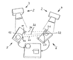
図1は、対象物1を3Dデジタル化する方法を実施するための装置の一実施形態を示す。この装置は、カメラと白色光ストリップ投影機とを有するセンサ2を備えている。
FIG. 1 shows an embodiment of an apparatus for implementing a method for 3D digitizing an
本方法の実施中に、センサ2は、最初は、3で表される位置にある。この位置において、対象物1の第1カメラ画像を記録する。このカメラ画像を記録する際、対象物1に白色光ストリップを照射する。このカメラ画像は、対象物1の3D座標を決定する機能を果たす。このために、様々な方法を採用することができる。特に、対象物1の3D座標を単一のカメラ画像から決定することができる空間位相シフト方法を採用してもよい。しかしながら、対象物1の3D座標を決定するために複数の、特に3つ又は4つのカメラ画像を記録する時間ベースの位相シフト方法を採用してもよい。
During the implementation of the method, the
さらに、対象物1の写真5を、センサ2は同じ位置のまま、センサ2のカメラで撮影する。この写真を撮影する際は、対象物1に白色光ストリップを照らさない。
Further, the
続いて、センサ2を、図1では参照番号4を付した別な位置へ移動させる。この位置において、対象物1の別なカメラ画像を記録する。このカメラ画像から、対象物1の3D座標が決定される。このカメラ画像を記録する際、センサ2の投影機によって対象物1に白色光ストリップを投影する。前記のように、対象物の3D座標をカメラ画像によって決定することができる。しかしながら、特に時間ベースの位相シフト方法を採用する場合、対象物1の複数のカメラ画像を記録し、複数のカメラ画像から対象物1の3D座標を決定することもできる。センサ2が位置4にある間に、白色光ストリップを対象物1に投影せずに対象物1の写真6を撮影する。
Subsequently, the
センサ2が位置3にある場合に得られる1つ又は複数のカメラ画像と写真5とは、対象物1の図1の左に示す領域をカバーしている。センサ2が位置4にある場合、1つ又は複数のカメラ画像と写真6とは、対象物1の右側領域をカバーしている。対象物1のこれらの領域は互いに部分的に重なり合っている。
One or a plurality of camera images and a
対象物1の写真5,6から、複数の2D特徴点を決定する。対象物1の左側部分をカバーする写真5から、特徴点11,12,13を決定する。これらの特徴点は、対象物1の角に、すなわち、2つの辺が交わる点にある。
A plurality of 2D feature points are determined from the
対象物1の右側部分をカバーする写真6から、2D特徴点21,22,23を決定する。これらの2D特徴点も、対象物1の角にある。
The 2D feature points 21, 22, and 23 are determined from the photograph 6 that covers the right portion of the
続いて、2D特徴点11,12,13;21,22,23の3D座標を決定する。3D座標は、対象物1のカメラ画像から決定される。
Subsequently, 3D coordinates of 2D feature points 11, 12, 13; 21, 22, 23 are determined. The 3D coordinates are determined from the camera image of the
さらに、左側写真5と右側写真6との間で互いに対応する2D特徴点11,21;12,22;13,23からなる2D点対応組31,32,33を複数組決定する。これらの2D点対応組31,32,33を、図1に破線で示す。
Further, a plurality of 2D
続いて、前記決定した複数組の2D点対応組31,32,33の中から複数組の2D点対応組を選択する。図1では、3組の2D点対応組31,32,33を選択する。これらの2D点対応組の中から3D変換対象(ここでは、2D点対応組31,32,33)を決定する。
Subsequently, a plurality of 2D point correspondence groups are selected from the plurality of determined 2D
次いで、前記3D変換対象の品質を、該3D変換対象における2D特徴点の変換された3D座標を参照して決定(測定)する。ここでは、この3D変換対象の品質の決定には、2D特徴点11,21;12,22;13,23の3D座標が適用される。 Next, the quality of the 3D conversion target is determined (measured) with reference to the converted 3D coordinates of the 2D feature points in the 3D conversion target. Here, the 3D coordinates of 2D feature points 11, 21; 12, 22; 13, 23 are applied to determine the quality of the 3D conversion target.
前記決定した3D変換対象の品質に基づいて、有効3D特徴点を決定する。図1において、2D点対応組31,32,33に属する3D変換対象は、有効3D変換対象である、すなわち、十分な品質の3D変換対象である。この有効3D変換対象から、有効3D特徴点を決定することができる。 Based on the determined quality of the 3D conversion target, effective 3D feature points are determined. In FIG. 1, 3D conversion objects belonging to the 2D point correspondence sets 31, 32, 33 are effective 3D conversion objects, that is, 3D conversion objects of sufficient quality. Effective 3D feature points can be determined from this effective 3D conversion target.
続いて、有効3D特徴点の3D座標を使用して、対象物1の左右のカメラ画像を組み合わせる。この組み合わせは、3D照合処理によって行われる。このようにして、図1に示すように、対象物1を正しく組み合わせることができる。
Subsequently, the left and right camera images of the
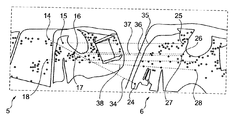
図2は別な対象物を示す。この対象物の第1写真5は、ある特定の視点から写されたものであり、第2写真6は別の視点から写されたものである。写真5,6によってカバーされる対象物の領域は、互いに部分的に重なり合っている。
FIG. 2 shows another object. The
写真5に、決定された多数の2D特徴点、例えば、2D特徴点14,15,16,17,18が表されている。写真6には、多数の2D特徴点のうち2D特徴点24,25,26,27,28が表されている。
The
2D特徴点14,24;15,25;16,26:17,27;18,28は、2D点対応組34,35,36,37,38にそれぞれ含まれる。 The 2D feature points 14, 24; 15, 25; 16, 26: 17, 27; 18, 28 are included in the 2D point correspondence sets 34, 35, 36, 37, 38, respectively.
これらの2D点対応組から3組の2D点対応組をランダムに選択する。これら選択した3組の2D点対応組から、3D変換対象を決定する。続いて、この3D変換対象の品質を、該3D変換対象における2D特徴点の3D座標を参照して決定(測定)する。この品質が十分である場合、これら3D変換対象の中から有効3D特徴点を決定し、有効3D特徴点の3D座標を使用して、写真5,6に属するカメラ画像を組み合わせる。品質が十分でない場合、前記3組の他の2D点対応組を選択して3D変換対象を決定し、その品質を決定する。有効3D変換対象が得られるまで、このシーケンスをその都度他の3組の2D点対応組で繰り返してもよい。
From these 2D point corresponding groups, three 2D point corresponding groups are selected at random. A 3D conversion target is determined from the selected three sets of 2D point correspondence. Subsequently, the quality of the 3D conversion target is determined (measured) with reference to the 3D coordinates of the 2D feature points in the 3D conversion target. If this quality is sufficient, effective 3D feature points are determined from these 3D conversion targets, and the camera images belonging to the
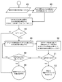
図3A及び図3Bは、対象物を3Dデジタル化するための方法のフローチャートをそれぞれ示す。 3A and 3B show flowcharts of a method for 3D digitizing an object, respectively.
第1ステップ41において、対象物の表面の3D測定を実施する。この3D測定では、対象物の3D座標を決定するために、対象物の1つ又は複数のカメラ画像を記録する。1つ又は複数のカメラ画像は、ある特定の視点から記録する。1つ又は複数のカメラ画像から、対象物の一部が記録される。これらは、対象物の3D座標を決定することができる1つ又は複数のカメラ画像である。
In the
ステップ42において、1つ又は複数のカメラ画像をマスキングする。すなわち、不要な背景情報を排除する。このステップにおいて、1つ又は複数のカメラ画像の対象物領域を決定する。
In
ステップ43において、2D特徴点を計算する。
In
ステップ44において、2D特徴点の3D座標を決定する。
In
ステップ44′において、特徴点リストを記憶装置に格納する。この特徴点リストは、全ての計算された2D特徴点と、全ての2D特徴点の3D座標とを含む。 In step 44 ', the feature point list is stored in the storage device. This feature point list includes all calculated 2D feature points and the 3D coordinates of all 2D feature points.
続いて、カメラを別な視点にして、ステップ41から44′を繰り返す。このカメラ視点では、対象物の別な部分領域をカバーする。なお、この別な部分領域は、対象物の既にカバーした部分領域に部分的に重なり合う領域のことである。 Subsequently, steps 41 to 44 'are repeated with the camera as another viewpoint. This camera viewpoint covers another partial area of the object. The other partial area is an area that partially overlaps the already covered partial area of the object.
続いて、ステップ45(図3B)を実施して、現在の写真、つまり第2写真の特徴点リストをリストAとして使用する。 Subsequently, Step 45 (FIG. 3B) is performed, and the feature point list of the current photo, that is, the second photo is used as the list A.
続くステップ46において、特徴点リストを、先の写真の全ての特徴点から作成するか、又は、記憶装置から取り出してリストBとして使用する。
In the following
ステップ47において、リストAとリストBとの間で2D点対応組を決定する。互いに対応関係にある、リストA及びリストBの特徴点は、リストA’及びリストB’として作成され、場合によっては格納される。リストA’における特徴点の数|A’|は、リストB’における特徴点の数|B’|に等しい。
In
ステップ48において、リストA’及びリストB’における特徴点の数が少なくとも3つであるかどうかをチェックする。少なくとも3つなければ、ステップ54において、事前アライメントの自動決定が不可であると示される。この場合、3D変換対象を、2D点対応組から決定することはできない。
In
リストA’及びリストB’における特徴点の数が少なくとも3つであれば、チェックステップ48の後に、ステップ49を実施する。このステップ49において、リストA’から3つの特徴点をランダムに選択する。これら3つの特徴点は、3組の2D点対応組に属し、これら3つの特徴点から、3D変換対象を決定する。この3D変換対象に基づいて、2D特徴点の3D座標を決定する。3D変換対象は、リストA’から選択した2D特徴点の3D位置の画像を、リストB’における当該2D点対応組の2D特徴点において形成する。
If the number of feature points in list A 'and list B' is at least three,
ステップ50において、決定された3D変換対象の品質を測定する。この測定は、3D変換対象における2D特徴点の変換された3D座標の3次元ギャップ、つまり先のデータ記録に関して変換されたデータ記録の3Dギャップの評価を参照して行われる。
In
ステップ51において、この品質が十分かどうかをチェックする。品質が十分であれば、ステップ52において、有効な事前アライメントが見出されたと示される。決定した3D変換対象を使用して、特に3D照合処理によってカメラ画像を組み合わせることができる。
In
その後、処理はステップ41(図3A)へ続いてもよい。 Thereafter, processing may continue to step 41 (FIG. 3A).
逆に、ステップ51において3D変換の品質が十分でないと示されたならば、ステップ53において、試験の最大数に達したかどうかをチェックする。達していなければ、ステップ49を再び実施し、ステップ49において、3つの他の特徴点をランダムに選択する。
Conversely, if
逆に、試験の最大数に達していれば、ステップ54において、事前アライメントの自動決定が不可であると示される。
Conversely, if the maximum number of tests has been reached,
本発明により、カメラ画像の3D照合を自動的に実施することができ、ユーザの操作が不要となる方法及び装置が提供される。さらに、本発明は、ユーザの操作が少なくとも明らかに低減されるように実現され得る。特に、3Dスキャナの各オブジェクトビューによって対象物の1つ又は複数の追加写真を撮影することができるように、処理を実行することができる。このため、3Dセンサのカメラを使用してもよい。対象物デジタル化に必要なストリップ画像カメラ画像に加えて、1つ又は複数の追加写真を、ストリップ照明なしで撮影してもよい。これらの写真から、対象物の2D特徴点を計算することができる。特徴点として、特に、形状の端部又はコントラスト端部などの対象物の顕著な点を使用してもよい。 According to the present invention, there is provided a method and an apparatus that can automatically perform 3D collation of camera images and do not require user operation. Furthermore, the present invention can be implemented such that user operations are at least clearly reduced. In particular, the process can be performed so that each object view of the 3D scanner can take one or more additional pictures of the object. For this reason, a 3D sensor camera may be used. In addition to the strip image camera images required for object digitization, one or more additional photos may be taken without strip lighting. From these photographs, the 2D feature points of the object can be calculated. As a feature point, a prominent point of an object such as an edge of a shape or a contrast edge may be used.
一般的に、オブジェクトビューをあまり変更しない場合には、3D変換対象の品質はより良好となる。有効3D変換対象を決定できないならば、有効3D変換対象を得るためのオブジェクトビューの変更を少なくして、本発明の方法を再び実施してもよい。あるいは、又は、それに加えて、様々なオブジェクトビューの間の可視領域の重なりをより大きくして、本発明の方法を実施してもよい。 In general, when the object view is not changed much, the quality of the 3D conversion target is better. If the effective 3D conversion target cannot be determined, the method of the present invention may be performed again with fewer object view changes to obtain the effective 3D conversion target. Alternatively, or in addition, the method of the present invention may be implemented with greater visibility overlap between the various object views.
3D変換対象の品質が十分でない場合には、さらに、形状的な対応関係を印付けすることによって、事前アライメントを手動で行うことができる。 If the quality of the 3D conversion target is not sufficient, pre-alignment can be performed manually by marking the shape correspondence.
複数の2D特徴点を、対象物の3D座標を決定するためのカメラ画像の作成をも行うカメラによって撮影した複数の写真から決定してもよい。しかしながら、別個のカメラの写真から2D特徴点を決定することも可能である。3Dデジタル化の前又は後に、対象物の一連の写真を、別個のカメラで生成することができ、対象物の2D特徴点を、これらの写真から計算することができる。このようにして得られた特徴点リストを、続いて使用することができる。特徴点リストを、3Dデジタル化を開始する前に測定プログラムへロードしてもよい。 A plurality of 2D feature points may be determined from a plurality of photographs taken by a camera that also creates a camera image for determining the 3D coordinates of the object. However, it is also possible to determine 2D feature points from separate camera photos. Before or after 3D digitization, a series of photographs of the object can be generated with a separate camera, and 2D feature points of the object can be calculated from these photographs. The feature point list thus obtained can subsequently be used. The feature point list may be loaded into the measurement program before starting 3D digitization.
対象物が3Dデジタル化に不十分な構造を有している場合、2Dマークによって、例えば、マーカーペンなどによって付けることのできるランダムパターンによって、処理に必要な表面構造を作成することができる。 If the object has a structure that is insufficient for 3D digitization, the surface structure required for processing can be created with a 2D mark, for example, with a random pattern that can be applied with a marker pen or the like.
センサ位置と測定体積とを3D空間において実況で示すことができる。決定された特徴点を使用して、対象物に対して相対的なセンサ位置を決定することができる。対象物及び/又はセンサの位置決定のための視覚的補助をユーザに提供するために、前記センサ位置情報によって、測定対象物に関するセンサ位置及び測定体積を、データ取得ソフトウエアにおいてリアルタイムベースで視覚化することができる。このことは、特に、ラフで迅速な3D事前測定によって行える。 The sensor position and measurement volume can be shown live in 3D space. The determined feature points can be used to determine a sensor position relative to the object. In order to provide the user with visual assistance for determining the position of the object and / or sensor, the sensor position information visualizes the sensor position and the measurement volume with respect to the measurement object on a real-time basis in the data acquisition software. can do. This can be done in particular by rough and rapid 3D pre-measurement.
1 対象物
2 センサ
5,6 写真
11,12,13 2D特徴点
21,22,23 2D特徴点
14,15,16,17,18 2D特徴点
24,25,26,27,28 2D特徴点
31,32,33 2D点対応組
34,35,36,37,38 2D点対応組
DESCRIPTION OF
Claims (9)
前記対象物(1)を撮影した写真(5,6)から、前記対象物(1)の2D特徴点(11,12,13;21,22,23;14,15,16,17,18;24,25,26,27,28)を決定し、
前記2D特徴点の3D座標を決定し、
一の写真と別の写真との間で互いに対応する2D特徴点からなる2D点対応組(31,32,33;34,35,36,37,38)を複数組決定し、
前記決定した複数組の2D点対応組の中から複数組の2D点対応組を選択して3D変換対象を決定し、
前記3D変換対象の品質を、前記2D特徴点の前記3D座標を参照して決定して、該3D変換対象の中から有効3D特徴点を決定し、
前記有効3D特徴点の3D座標を、前記対象物の前記カメラ画像を組み合わせるために使用することを特徴とする方法。 A method for digitizing an object, wherein a plurality of camera images of the object (1) are recorded and combined to determine 3D coordinates of the object (1),
From the photographs (5, 6) taken of the object (1), the 2D feature points (11, 12, 13; 21, 22, 23; 14, 15, 16, 17, 18) of the object (1); 24, 25, 26, 27, 28)
Determining 3D coordinates of the 2D feature points;
Determining a plurality of 2D point correspondence sets (31, 32, 33; 34, 35, 36, 37, 38) composed of 2D feature points corresponding to each other between one photo and another photo;
A plurality of 2D point correspondence groups are selected from the determined plurality of 2D point correspondence groups to determine a 3D conversion target;
Determining the quality of the 3D conversion target with reference to the 3D coordinates of the 2D feature point, and determining an effective 3D feature point from the 3D conversion target;
A method characterized in that the 3D coordinates of the effective 3D feature points are used to combine the camera images of the object.
各写真(5,6)において対象物領域を決定し、
前記対象物領域内の2D特徴点(14,15,16,17,18;24,25,26,27,28)を使用することを特徴とする方法。 The method of claim 1, wherein
Determine the object area in each photo (5, 6),
Method using 2D feature points (14, 15, 16, 17, 18; 24, 25, 26, 27, 28) in the object area.
格納された前記2D特徴点、格納された前記3D特徴点、及び、格納された特徴ベクトルのうちの少なくとも1つを使用することを特徴とする方法。 The method according to claim 1 or 2, wherein
A method using at least one of the stored 2D feature points, the stored 3D feature points, and stored feature vectors.
前記2D特徴点、前記3D特徴点、及び、特徴ベクトルのうちの少なくとも1つを、前記対象物のCADデータの描画から決定することを特徴とする方法。 The method according to any one of claims 1 to 3, wherein
A method of determining at least one of the 2D feature point, the 3D feature point, and a feature vector from drawing of CAD data of the object.
前記対象物のCADデータの描画から決定した、前記2D特徴点、前記3D特徴点、及び、特徴ベクトルのうちの少なくとも1つを使用することを特徴とする方法。 The method according to any one of claims 1 to 4, wherein
A method using at least one of the 2D feature points, the 3D feature points, and feature vectors determined from drawing CAD data of the object.
前記対象物(1)に対して光パターン又はレーザ光パターンを投影するための投影機と、
前記対象物のカメラ画像を記録するための1つ又は複数のカメラと、
前記対象物の前記カメラ画像を組み合わせ、前記対象物の3D座標を決定するための手段と、
前記対象物の写真を作成するためのカメラと、
前記対象物の2D特徴点を決定し、かつ、前記対象物の前記2D特徴点の3D座標を決定し、かつ、一の写真と別の写真との間で互いに対応する2D特徴点からなる2D点対応組を複数組決定し、かつ、前記決定した複数組の2D点対応組の中から複数組の2D点対応組を選択して3D変換対象を決定し、かつ、前記3D変換対象の品質を、前記2D特徴点の3D座標を参照して決定し、かつ、有効3D特徴点を決定するための手段とを備えることを特徴とする装置。 An apparatus for carrying out a method for 3D digitizing an object comprising:
A projector for projecting a light pattern or a laser light pattern onto the object (1);
One or more cameras for recording camera images of the object;
Means for combining the camera images of the object and determining 3D coordinates of the object;
A camera for creating a photograph of the object;
2D feature points of the object are determined, 3D coordinates of the 2D feature points of the object are determined, and 2D feature points corresponding to each other between one photo and another photo A plurality of point-corresponding sets are determined, a plurality of 2D point-corresponding sets are selected from the determined plurality of 2D point-corresponding sets, a 3D conversion target is determined, and the quality of the 3D conversion target And means for determining effective 3D feature points with reference to 3D coordinates of the 2D feature points.
前記写真の対象物領域を決定するための手段を更に備えることを特徴とする装置。 The apparatus of claim 6.
The apparatus further comprising means for determining an object region of the photograph.
前記2D特徴点、前記3D特徴点、及び、特徴ベクトルの少なくとも1つを格納するための記憶装置を更に備えることを特徴とする装置。 The device according to claim 6 or 7,
An apparatus further comprising a storage device for storing at least one of the 2D feature point, the 3D feature point, and a feature vector.
前記2D特徴点、前記3D特徴点、及び、特徴ベクトルを、前記対象物のCADデータの描画から決定するための手段を更に備えることを特徴とする装置。 The device according to any one of claims 6 to 8,
The apparatus further comprising means for determining the 2D feature point, the 3D feature point, and a feature vector from drawing of CAD data of the object.
Applications Claiming Priority (2)
| Application Number | Priority Date | Filing Date | Title |
|---|---|---|---|
| DE102008031942.2 | 2008-06-07 | ||
| DE102008031942A DE102008031942A1 (en) | 2008-07-07 | 2008-07-07 | Method and device for 3D digitizing an object |
Publications (2)
| Publication Number | Publication Date |
|---|---|
| JP2010014718A true JP2010014718A (en) | 2010-01-21 |
| JP5453000B2 JP5453000B2 (en) | 2014-03-26 |
Family
ID=41019838
Family Applications (1)
| Application Number | Title | Priority Date | Filing Date |
|---|---|---|---|
| JP2009160969A Expired - Fee Related JP5453000B2 (en) | 2008-07-07 | 2009-07-07 | Method and apparatus for 3D digitizing an object |
Country Status (4)
| Country | Link |
|---|---|
| US (1) | US8330803B2 (en) |
| EP (1) | EP2144036B1 (en) |
| JP (1) | JP5453000B2 (en) |
| DE (1) | DE102008031942A1 (en) |
Cited By (2)
| Publication number | Priority date | Publication date | Assignee | Title |
|---|---|---|---|---|
| US20150259811A1 (en) * | 2013-09-06 | 2015-09-17 | Permelec Electrode Ltd. | Production method for electrode for electrolysis |
| JP2016048239A (en) * | 2014-08-27 | 2016-04-07 | ステインビッヒラー オプトテヒニク ゲゼルシャフト ミット ベシュレンクテル ハフツング | Method and device for measuring 3-d coordinates of object |
Families Citing this family (24)
| Publication number | Priority date | Publication date | Assignee | Title |
|---|---|---|---|---|
| US9479768B2 (en) * | 2009-06-09 | 2016-10-25 | Bartholomew Garibaldi Yukich | Systems and methods for creating three-dimensional image media |
| DE102010034987A1 (en) | 2010-08-20 | 2012-03-01 | Steinbichler Optotechnik Gmbh | Method for 3D digitizing a variable surface object |
| US8754929B1 (en) * | 2011-05-23 | 2014-06-17 | John Prince | Real time vergence control for 3D video capture and display |
| EP2698763A1 (en) * | 2012-08-14 | 2014-02-19 | Hölscher & Leuschner GmbH & Co. | Method for analysing a living livestock animal |
| DE102012024012A1 (en) * | 2012-12-06 | 2014-06-26 | Audi Ag | Method for determining measurement object adapted for adjusting parameter of optical measuring device, involves determining parameter of virtual replica of measuring device to adjust measuring device below use of parameter |
| JP6566768B2 (en) * | 2015-07-30 | 2019-08-28 | キヤノン株式会社 | Information processing apparatus, information processing method, and program |
| DE102016211657A1 (en) | 2016-06-28 | 2017-12-28 | Carl Zeiss Industrielle Messtechnik Gmbh | Method and apparatus for producing a resulting image of a surface |
| FR3063172A1 (en) | 2017-02-21 | 2018-08-24 | Yann Viellard | DEVICE AND METHOD FOR CONTACTLESS 3D SCANNING OF AN OBJECT. |
| EP3444780A1 (en) | 2017-08-18 | 2019-02-20 | a.tron3d GmbH | Method for registering at least two different 3d models |
| CN111492262A (en) | 2017-10-08 | 2020-08-04 | 魔眼公司 | Distance measurement using warp-wise grid pattern |
| CN108195314B (en) * | 2018-01-17 | 2019-11-05 | 杨佳苗 | Reflective striped three dimension profile measurement method based on more field stitchings |
| KR20200123483A (en) | 2018-03-20 | 2020-10-29 | 매직 아이 인코포레이티드 | 3D depth detection and adjustment of camera exposure for 2D imaging |
| JP7292315B2 (en) | 2018-06-06 | 2023-06-16 | マジック アイ インコーポレイテッド | Distance measurement using high density projection pattern |
| WO2020033169A1 (en) | 2018-08-07 | 2020-02-13 | Magik Eye Inc. | Baffles for three-dimensional sensors having spherical fields of view |
| US11483503B2 (en) | 2019-01-20 | 2022-10-25 | Magik Eye Inc. | Three-dimensional sensor including bandpass filter having multiple passbands |
| DE102019103429A1 (en) * | 2019-02-12 | 2020-08-13 | Volume Graphics Gmbh | Computer-implemented method for determining surfaces in measurement data |
| US11474209B2 (en) | 2019-03-25 | 2022-10-18 | Magik Eye Inc. | Distance measurement using high density projection patterns |
| JP2022532725A (en) * | 2019-05-12 | 2022-07-19 | マジック アイ インコーポレイテッド | Mapping of 3D depth map data onto a 2D image |
| CN110018174B (en) * | 2019-05-22 | 2021-10-22 | 合肥联宝信息技术有限公司 | Method and device for detecting object appearance |
| JP2023504157A (en) | 2019-12-01 | 2023-02-01 | マジック アイ インコーポレイテッド | Improving triangulation-based 3D range finding using time-of-flight information |
| KR20220122645A (en) | 2019-12-29 | 2022-09-02 | 매직 아이 인코포레이티드 | Associating 3-D coordinates with 2-D feature points |
| WO2021138677A1 (en) | 2020-01-05 | 2021-07-08 | Magik Eye Inc. | Transferring the coordinate system of a three-dimensional camera to the incident point of a two-dimensional camera |
| DE102020201097B4 (en) * | 2020-01-30 | 2023-02-16 | Carl Zeiss Industrielle Messtechnik Gmbh | Arrangement and method for optical determination of object coordinates |
| CN111586449B (en) * | 2020-04-15 | 2021-11-19 | 中影华夏电影科技(北京)有限公司 | Method and system for synchronously playing main and auxiliary server films |
Citations (3)
| Publication number | Priority date | Publication date | Assignee | Title |
|---|---|---|---|---|
| JPH09212643A (en) * | 1996-02-05 | 1997-08-15 | Meidensha Corp | Method for recognition of three-dimensional object and device therefor |
| JP2003006618A (en) * | 2001-06-27 | 2003-01-10 | Minolta Co Ltd | Method and device for generating three-dimensional model and computer program |
| JP2005202945A (en) * | 2003-12-17 | 2005-07-28 | United Technol Corp <Utc> | Cad modeling system and method |
Family Cites Families (7)
| Publication number | Priority date | Publication date | Assignee | Title |
|---|---|---|---|---|
| JP2000194863A (en) * | 1998-12-28 | 2000-07-14 | Nippon Telegr & Teleph Corp <Ntt> | Three-dimensional structure acquisition/restoration method and device and storage medium recording three- dimensional structure acquisition/restoration program |
| JP3751770B2 (en) * | 1999-07-08 | 2006-03-01 | 富士通株式会社 | 3D shape generator |
| US7327857B2 (en) * | 2004-03-09 | 2008-02-05 | General Electric Company | Non-contact measurement method and apparatus |
| ATE518113T1 (en) * | 2005-03-11 | 2011-08-15 | Creaform Inc | SELF-REFERENCED THREE-DIMENSIONAL SCANNING SYSTEM AND APPARATUS |
| US20070052700A1 (en) * | 2005-09-07 | 2007-03-08 | Wheeler Frederick W | System and method for 3D CAD using projection images |
| JP5362189B2 (en) * | 2006-05-10 | 2013-12-11 | 株式会社トプコン | Image processing apparatus and processing method thereof |
| US7925049B2 (en) * | 2006-08-15 | 2011-04-12 | Sri International | Stereo-based visual odometry method and system |
-
2008
- 2008-07-07 DE DE102008031942A patent/DE102008031942A1/en not_active Withdrawn
-
2009
- 2009-06-29 EP EP09008467.4A patent/EP2144036B1/en not_active Not-in-force
- 2009-07-06 US US12/459,640 patent/US8330803B2/en active Active
- 2009-07-07 JP JP2009160969A patent/JP5453000B2/en not_active Expired - Fee Related
Patent Citations (3)
| Publication number | Priority date | Publication date | Assignee | Title |
|---|---|---|---|---|
| JPH09212643A (en) * | 1996-02-05 | 1997-08-15 | Meidensha Corp | Method for recognition of three-dimensional object and device therefor |
| JP2003006618A (en) * | 2001-06-27 | 2003-01-10 | Minolta Co Ltd | Method and device for generating three-dimensional model and computer program |
| JP2005202945A (en) * | 2003-12-17 | 2005-07-28 | United Technol Corp <Utc> | Cad modeling system and method |
Cited By (4)
| Publication number | Priority date | Publication date | Assignee | Title |
|---|---|---|---|---|
| US20150259811A1 (en) * | 2013-09-06 | 2015-09-17 | Permelec Electrode Ltd. | Production method for electrode for electrolysis |
| US9903031B2 (en) * | 2013-09-06 | 2018-02-27 | De Nora Permelec Ltd | Production method for electrode for electrolysis |
| JP2016048239A (en) * | 2014-08-27 | 2016-04-07 | ステインビッヒラー オプトテヒニク ゲゼルシャフト ミット ベシュレンクテル ハフツング | Method and device for measuring 3-d coordinates of object |
| US10502554B2 (en) | 2014-08-27 | 2019-12-10 | Carl Zeiss Optotechnik GmbH | Process and device for determining the 3D coordinates of an object |
Also Published As
| Publication number | Publication date |
|---|---|
| DE102008031942A1 (en) | 2010-01-14 |
| EP2144036A3 (en) | 2011-04-06 |
| US8330803B2 (en) | 2012-12-11 |
| JP5453000B2 (en) | 2014-03-26 |
| EP2144036A2 (en) | 2010-01-13 |
| US20100007719A1 (en) | 2010-01-14 |
| EP2144036B1 (en) | 2018-09-05 |
Similar Documents
| Publication | Publication Date | Title |
|---|---|---|
| JP5453000B2 (en) | Method and apparatus for 3D digitizing an object | |
| US9569873B2 (en) | Automated iterative image-masking based on imported depth information | |
| US9396542B2 (en) | Method of estimating imaging device parameters | |
| JP6793151B2 (en) | Object tracking device, object tracking method and object tracking program | |
| TW201118791A (en) | System and method for obtaining camera parameters from a plurality of images, and computer program products thereof | |
| WO2012096747A1 (en) | Forming range maps using periodic illumination patterns | |
| JP2010287174A (en) | Furniture simulation method, device, program, recording medium | |
| JP2010219825A (en) | Photographing device for three-dimensional measurement | |
| CN107370950B (en) | Focusing process method, apparatus and mobile terminal | |
| CN107465906A (en) | Panorama shooting method, device and the terminal device of scene | |
| EP3382645A2 (en) | Method for generation of a 3d model based on structure from motion and photometric stereo of 2d sparse images | |
| CN109934873B (en) | Method, device and equipment for acquiring marked image | |
| JP6541920B1 (en) | INFORMATION PROCESSING APPARATUS, PROGRAM, AND INFORMATION PROCESSING METHOD | |
| US20230328400A1 (en) | Auxiliary focusing method, apparatus, and system | |
| CN110390645A (en) | The system and method for improvement 3D data reconstruction for three-dimensional instantaneous picture sequence | |
| JP2004280776A (en) | Method for determining shape of object in image | |
| CN104700392B (en) | Virtual image positioning method and device | |
| US10360719B2 (en) | Method and apparatus for obtaining high-quality textures | |
| JP2002135807A (en) | Method and device for calibration for three-dimensional entry | |
| CN111489384A (en) | Occlusion assessment method, device, equipment, system and medium based on mutual view | |
| EP4171015A1 (en) | Handling blur in multi-view imaging | |
| WO2022102015A1 (en) | Image information acquisition device, image information acquisition method, and computer program | |
| TWI768231B (en) | Information processing device, recording medium, program product, and information processing method | |
| Liu et al. | Star-effect simulation for photography | |
| KR101989369B1 (en) | method of providing automatic calibratiion of SVM video processing based on marker homography transformation |
Legal Events
| Date | Code | Title | Description |
|---|---|---|---|
| A621 | Written request for application examination |
Free format text: JAPANESE INTERMEDIATE CODE: A621 Effective date: 20120618 |
|
| RD02 | Notification of acceptance of power of attorney |
Free format text: JAPANESE INTERMEDIATE CODE: A7422 Effective date: 20120913 |
|
| A977 | Report on retrieval |
Free format text: JAPANESE INTERMEDIATE CODE: A971007 Effective date: 20130628 |
|
| A131 | Notification of reasons for refusal |
Free format text: JAPANESE INTERMEDIATE CODE: A131 Effective date: 20130723 |
|
| A521 | Request for written amendment filed |
Free format text: JAPANESE INTERMEDIATE CODE: A523 Effective date: 20131022 |
|
| TRDD | Decision of grant or rejection written | ||
| A01 | Written decision to grant a patent or to grant a registration (utility model) |
Free format text: JAPANESE INTERMEDIATE CODE: A01 Effective date: 20131217 |
|
| A61 | First payment of annual fees (during grant procedure) |
Free format text: JAPANESE INTERMEDIATE CODE: A61 Effective date: 20140106 |
|
| R150 | Certificate of patent or registration of utility model |
Ref document number: 5453000 Country of ref document: JP Free format text: JAPANESE INTERMEDIATE CODE: R150 Free format text: JAPANESE INTERMEDIATE CODE: R150 |
|
| R250 | Receipt of annual fees |
Free format text: JAPANESE INTERMEDIATE CODE: R250 |
|
| R250 | Receipt of annual fees |
Free format text: JAPANESE INTERMEDIATE CODE: R250 |
|
| R250 | Receipt of annual fees |
Free format text: JAPANESE INTERMEDIATE CODE: R250 |
|
| R250 | Receipt of annual fees |
Free format text: JAPANESE INTERMEDIATE CODE: R250 |
|
| R250 | Receipt of annual fees |
Free format text: JAPANESE INTERMEDIATE CODE: R250 |
|
| R250 | Receipt of annual fees |
Free format text: JAPANESE INTERMEDIATE CODE: R250 |
|
| LAPS | Cancellation because of no payment of annual fees |